EP2435637B1 - Greifelement für ein arbeitswerkzeug - Google Patents
Greifelement für ein arbeitswerkzeug Download PDFInfo
- Publication number
- EP2435637B1 EP2435637B1 EP10722322.4A EP10722322A EP2435637B1 EP 2435637 B1 EP2435637 B1 EP 2435637B1 EP 10722322 A EP10722322 A EP 10722322A EP 2435637 B1 EP2435637 B1 EP 2435637B1
- Authority
- EP
- European Patent Office
- Prior art keywords
- gripping
- overbite
- block
- gripping member
- edge
- Prior art date
- Legal status (The legal status is an assumption and is not a legal conclusion. Google has not performed a legal analysis and makes no representation as to the accuracy of the status listed.)
- Active
Links
Images

Classifications
-
- E—FIXED CONSTRUCTIONS
- E02—HYDRAULIC ENGINEERING; FOUNDATIONS; SOIL SHIFTING
- E02F—DREDGING; SOIL-SHIFTING
- E02F3/00—Dredgers; Soil-shifting machines
- E02F3/04—Dredgers; Soil-shifting machines mechanically-driven
- E02F3/28—Dredgers; Soil-shifting machines mechanically-driven with digging tools mounted on a dipper- or bucket-arm, i.e. there is either one arm or a pair of arms, e.g. dippers, buckets
- E02F3/36—Component parts
- E02F3/40—Dippers; Buckets ; Grab devices, e.g. manufacturing processes for buckets, form, geometry or material of buckets
- E02F3/402—Dippers; Buckets ; Grab devices, e.g. manufacturing processes for buckets, form, geometry or material of buckets with means for facilitating the loading thereof, e.g. conveyors
- E02F3/404—Dippers; Buckets ; Grab devices, e.g. manufacturing processes for buckets, form, geometry or material of buckets with means for facilitating the loading thereof, e.g. conveyors comprising two parts movable relative to each other, e.g. for gripping
-
- B—PERFORMING OPERATIONS; TRANSPORTING
- B66—HOISTING; LIFTING; HAULING
- B66C—CRANES; LOAD-ENGAGING ELEMENTS OR DEVICES FOR CRANES, CAPSTANS, WINCHES, OR TACKLES
- B66C3/00—Load-engaging elements or devices attached to lifting or lowering gear of cranes or adapted for connection therewith and intended primarily for transmitting lifting forces to loose materials; Grabs
- B66C3/02—Bucket grabs
-
- E—FIXED CONSTRUCTIONS
- E02—HYDRAULIC ENGINEERING; FOUNDATIONS; SOIL SHIFTING
- E02F—DREDGING; SOIL-SHIFTING
- E02F3/00—Dredgers; Soil-shifting machines
- E02F3/04—Dredgers; Soil-shifting machines mechanically-driven
- E02F3/28—Dredgers; Soil-shifting machines mechanically-driven with digging tools mounted on a dipper- or bucket-arm, i.e. there is either one arm or a pair of arms, e.g. dippers, buckets
- E02F3/36—Component parts
- E02F3/40—Dippers; Buckets ; Grab devices, e.g. manufacturing processes for buckets, form, geometry or material of buckets
- E02F3/413—Dippers; Buckets ; Grab devices, e.g. manufacturing processes for buckets, form, geometry or material of buckets with grabbing device
-
- E—FIXED CONSTRUCTIONS
- E02—HYDRAULIC ENGINEERING; FOUNDATIONS; SOIL SHIFTING
- E02F—DREDGING; SOIL-SHIFTING
- E02F3/00—Dredgers; Soil-shifting machines
- E02F3/04—Dredgers; Soil-shifting machines mechanically-driven
- E02F3/96—Dredgers; Soil-shifting machines mechanically-driven with arrangements for alternate or simultaneous use of different digging elements
- E02F3/965—Dredgers; Soil-shifting machines mechanically-driven with arrangements for alternate or simultaneous use of different digging elements of metal-cutting or concrete-crushing implements
-
- E—FIXED CONSTRUCTIONS
- E02—HYDRAULIC ENGINEERING; FOUNDATIONS; SOIL SHIFTING
- E02F—DREDGING; SOIL-SHIFTING
- E02F5/00—Dredgers or soil-shifting machines for special purposes
- E02F5/02—Dredgers or soil-shifting machines for special purposes for digging trenches or ditches
- E02F5/10—Dredgers or soil-shifting machines for special purposes for digging trenches or ditches with arrangements for reinforcing trenches or ditches; with arrangements for making or assembling conduits or for laying conduits or cables
Definitions
- This disclosure relates generally to an apparatus for gripping or cutting material with a work tool, and more particularly, to a gripping edge for a work tool.
- a grapple is generally a well known type of work tool that is often attached to machinery, such as excavators, backhoes etc.
- Applications of a grapple include material gripping, handling, or cutting capability. Used with an excavator, this gripping and handling capability makes the excavator suitable for a variety of operations.
- excavators employing grapple assemblies are often used in demolition (e.g, tearing down lightweight structures made of wood or brick, or sorting, picking, placing, and loading materials, or cutting materials if needed).
- grapples typically include two gripping members (sometimes referred to as blades or cutting edges) that are attachable to the grapple, and when brought together, grip the desired material. That is, the grapple has a shell, and these gripping members are each associated with one portion of the shell, such that as the shell is closed, the gripping members grip the material.
- gripping members sometimes referred to as blades or cutting edges
- the gripping members For new gripping members, if no material was involved and the shells were closed, the gripping members would contact each other on a gripping edge of the gripping member. As the gripping members wear, and more particularly, as the gripping edge of these members wear, an overbite forms between the members when they are brought together. For example, one gripping edge will go over the other gripping edge, instead of having the edges come together. This overbite can cause inefficiencies in gripping and cutting material.
- JP-U-454558 discloses a gripping member wherein blocks are located directly at a gripping edge, so that end surface of these blocks are the surfaces, which engage material to be gripped under normal operation of the gripping member.
- JP-U-51154880 discloses gripping members provided with the ribs or cones on their gripping edge, which engage a member to be gripped.
- US-A1-5056845 discloses gripping members provided with blocks at their gripping edges or surfaces.
- the gripping surfaces are big flat surfaces so that there is no risk of an overbite.
- US-B1-6405460 describes locking hook arms to be attached to the inside of the top of an excavator bucket. Furthermore, there is provided one specially designed fork. The hook arms and the fork are welded to opposite sides of a plate. The plate may be provided with cushion blocks to avoid a direct contact between a member to be handled and the blade.
- EP-A2-1679462 discloses a device for handling tubes, which device includes two gripping members provided with ribs at their surfaces, which contact the tube.
- US-A-5042219 discloses a flat steel anchor for precast concrete parts, which anchor has at least two hook-shaped bent sections formed in the anchoring area.
- the bent sections are of various shapes and curved downwardly and inwardly as to jointly define a continuous opening closed on either side to receive and retain a reinforcing rod.
- the bent sections are not movable with respect to each other.
- DE-A1-2936950 discloses a gripping member with a cutting edge at its bottom side, wherein at an inner side of the cutting edge there is provided a strip of elastic material extending along the cutting edge. Behind the elastic strip there is provided a cavity, to which a pressure medium can be supplied, so that the outer face of the strip extends beyond the cutting edge.
- DE-U1-9112470 discloses an excavator bucket with a front edge forming a knife bar and a additional knife bar, which can be mounted to the underside of the front edge of the bucket.
- the additional knife bar is formed similar to the knife bar according to Fig. 1 of the present application and does not include any overbite block.
- JP S 55-167980 U discloses a work tool with two grapples having gripping members at their opposing ends.
- a first member is attached to a top surface of a first gripping member and is formed with an edge which is slightly outward from the leading edge of the first gripping member.
- the second gripping member is provided at its upper surface with a second member being formed with a groove to adapt the protruding edge of the first member.
- First and second members extend along the whole length of the first and second gripping members.
- US-A1-20060048851 discloses a gripping member with a gripping edge which serves as the basis for the preamble of appended claim 1 formed by roller elements disposed in series one besides the other.
- the roller elements are rotatably mounted between webs protruding from a base body of the gripping member and forming an extension of its top surface and bottom surface.
- the rollers of the gripping edge are rolling on the ground, whereas the rollers of an opposed gripping edge of a clamshell grab are lying above each other during closure of the clamshell grab.
- the present invention is directed to overcome or improve one or more disadvantages associated with the prior methods and apparatus.
- a gripping member attachable to a work tool comprising a gripping member attachable to a work tool, the gripping member comprising a top surface, a bottom surface, a first gripping edge extending between the top surface and the bottom surface and having a length, wherein an overbite block is located proximate a middle portion of the length of the first gripping edge proximate to the first gripping edge.
- the overbite block having a depth that is less than the gripping edge width of the gripping edge such that the overbite block is slighting inboard from a leading edge of the gripping edge.
- a work tool which comprises two gripping members according to the first aspect of the present disclosure as mentioned above.
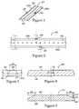
- Figures 1-5 illustrate a gripping member 101 having a top surface 102, a bottom surface 103, a first gripping edge 104a extending between the top surface 102 and the bottom surface 103 and having a length, and an overbite block 105 proximate the first gripping edge.
- the top surface 102 and bottom surface 103 are generally planar, however they may alternatively have some curvature.
- the gripping member 101 is attachable to a work tool, as will be described below, and may be reversible.
- the gripping member may have a second gripping edge 104b, wherein the second gripping edge 104b also has an overbite block 105. Therefore, when the first gripping edge 104a becomes worn, the gripping.member may be reversed such that edge 104b is now used when gripping material.
- the gripping member 101 may extend the complete available width of an associated grapple.
- the shaping and positioning of the overbite block 105 may be such that it does not interfere with normal operation of the gripping member 101 when attached to a grapple.
- the overbite block 105 has a depth 106 that is less than the gripping edge width 108 of the gripping edge 104 such that the overbite block 105 is slighting inboard from the leading edge 109 of the gripping edge 104 as best shown in Figure 5.
- Figure 3 shows that overbite block 105 may have a top width 111 that tapers outward via a taper width 112 to a wider base where it merges with the angled top of gripping edge 104.
- the overbite block 105 is located proximate a middle portion of the length of the gripping edge. In one embodiment, the overbite block may be located proximate the middle portion of the gripping edge length, but offcenter of the length. The overbite block 105 may be considered an extension of the top surface, the gripping edge, or the bottom surface. In one embodiment, the overbite block 105 may be located proximate one of the side surfaces of the gripping member. The function of the overbite block is to urge the edge surface into contact with another surface associated with the work tool (e.g., a second edge surface of a second member). In one embodiment, the overbite block 105 is a nub or a bump.
- overbite block 105 may have been machined on to be integral with gripping member 101, may be a separately machined uniform block of material welded onto gripping member 101, or may merely be a separate piece attached to gripping member with a suitable fastener(s). Therefore, the overbite block is located and configured in a manner such that it enables the edge surface to contact a second edge surface. In one embodiment, as will be discussed later, the overbite block enables the gripping edge to contact or engage a contact surface (such as a second gripping edge) on the work tool to achieve a desired position.
- a contact surface such as a second gripping edge
- the desired position may be a closed position where the edge surface is in contact, or substantially in contact with a second contact surface, such as a second edge surface.
- desired gripping position is a position where an overbite does not exist, and a gap in between the gripping surface and contact surface does not exists.
- the desired gripping position is the position where two gripping surfaces of respective gripping members are in contact with each other. Therefore, in one embodiment, as will be explained, the overbite block on one edge surface is configured to interact with a second gripping edge surface such that as either the first or second edge surfaces wear, the first gripping edge continues to substantially engage the second gripping edge surface.
- the overbite block is a nub, or bulge.
- the guide may take other structural forms attached to (or formed in) the gripping member to enable a gripping edge to achieve the desired gripping position.
- the gripping members may be attached to the work tool in a known manner, such as bolts or screws passing through holes 110 in the gripping member and into or through the respective shells of the work tool.
- the gripping edge may be a sloped edge, a beveled edge and/or a cutting edge (e.g, a bladed edge).
- the gripping member may be attachable to a work tool such as a grapple or some other form of work tool used to grip material, tear down structures, sort, pick, place, load or cut materials.
- a work tool such as a grapple or some other form of work tool used to grip material, tear down structures, sort, pick, place, load or cut materials.
- a work tool is a grapple.
- the grapple could be attached to an excavator or a back hoe.
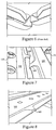
- the work tool may be configured to use two of these gripping members, as shown in Figure 7.
- Figure 7 shows that with the inclusion of overbite block 105, the overbite situation illustrated in Figure 6 is prevented.
- the associated cutting edge 104 will contact the overbite block 105 on the opposing gripping member to prevent the overbite situation as shown in Figure 6 , and maintain a better ability of the machine to function as normal even when these circumstances arise.
- Figure 8 merely shows a perspective view of one of the gripping members 101 shown from Figure 7 .
- a second embodiment of a gripping member 201 has three separate pieces in order to extend the complete width of grapple 10.
- This alternative structure may allow for different ones of the components 204 and 202 to be replaced or reversed depending up on different wear patterns rather than the complete gripping member 101 as shown in the earlier figures.
- the flanking components 204 may be identical to further reduce part count.
- the center piece 202 may include off center overbite blocks 205a and 205b on opposite sides thereof.
- overbite blocks 205a may be attached with fasteners, welded on, or integrally formed as a portion of component 202 when the same is machined from raw stock.
- the individual components 204 and 202 may be attached to grapple 10 using fasteners 206 in a conventional manner.
- Still another embodiment of the present disclosure includes a full width gripping member 301 that includes a bolt on overbite block 305 via a conventional fastener 206 when the gripping member 301 is attached to grapple 10.
- the gripping member 301 differs from a conventional gripping member in that it includes a cavity 302a and/or 302b for receiving the overbite block 305 with an associated shape and size.
- the overbite block 305 becomes attached to the gripping member 301 when the gripping member is attached to the grapple 10, but the two are otherwise unconnected when separated from the grapple 10.
- the grapple 410 that is modified to include a cavity 412 for receiving an appropriately sized and shaped overbite prevention block 405 that becomes attached to grapple 410 when a conventional bolt on cutting edge 15 is attached thereto with conventional fasteners 206.
- the overbite block 305 or 405 is formed from a uniform block of material with an appropriate size and shape to be received in the associated cavity of either the gripping member 301 or the grapple base bar 411, respectively.
- the overbite block includes a gripping member contact surface and a grapple base bar contact surface and includes a fastener bore extending through those surfaces.
- overbite block 405 it includes a gripping member contact surface that is contoured to match the top surface of a conventional bolt on cutting edge 15.
- the overbite block 305 and the overbite block 405 have a side surface shaped to match the respective cavity defined by either the gripping member 301 or grapple base bar 412.
- Figure 11 has an advantage in that only the base bar 411 of grapple 410 needs to be modified in order to accommodate an overbite block 405 associated with the present disclosure, and may be used with conventionally available bolt on cutting edges 15 of the type well known in the art. As each overbite prevention block would wear out, a replacement could easily be installed by detaching the conventional bolt on cutting edge 15 and installing a replacement overbite block 405.
- a grapple may have two gripping members attached to respective shells of the grapple. With new gripping members, the gripping surfaces will close to the desired position, when the shells are closed. However, as the gripping members wear, the overbite blocks enable the gripping surfaces to continue to close to the desired position (that is, the guide enables or urges the an edge surface to substantially be in contact with a second contact surface associated with the work tool, such as a second edge surface. For example, if the surfaces have worn to the point that traditional worn gripping surfaces would form an overbite, then using one embodiment of the present invention, as the shells close, the gripping surface that would otherwise close on the inside of the second gripping surface, would make contact with the overbite block associated with the second gripping surface.
- the inner gripping surface will be urged, or guided into contact with the second gripping surface, through engagement with the overbite block of the second gripping surface.
- overbite blocks on both gripping surfaces as shown in Fig. 7 , it does not matter how the overbite forms (or which gripping surface is going on the outside or inside of the other), an overbite block is contacted and enables the gripping surfaces to reach the desired gripping position.
- the overbite blocks are located on respective gripping surfaces such that they are not located directly across from each other.
- having the overbite block proximate the edge surface enables the overbite block to wear in approximate proportion with the edge surface.
- overbite block of the present disclosure can come in several different forms either as part of a bolt on cutting edge gripping member or a separate component that has an identity of its own prior to installation to a grapple 10.
- the design of Figure 11 may find favor in some instances since it requires no modification to the conventional bolt on cutting edges 15 currently being used with grapples on current machines. Instead, the only modification may be to the base bar 411 of the grapple 410 and a new part introduced, namely an overbite block 405.
- current machines could be modified by replacing the base bar 411 of their grapple 410 with a modified bar as shown in Figure 11 and then include, from time to time, replacement overbite blocks 405 to prevent the overbite situation illustrated in Figure 6 .
Landscapes
- Engineering & Computer Science (AREA)
- Mechanical Engineering (AREA)
- Structural Engineering (AREA)
- Mining & Mineral Resources (AREA)
- Civil Engineering (AREA)
- General Engineering & Computer Science (AREA)
- Shovels (AREA)
Claims (10)
- Greiferelement (101, 201, 301), das an einem Arbeitswerkzeug angebracht werden kann, wobei das Greiferelement (101, 201, 301) Folgendes umfasst:eine obere Fläche (102);eine untere Fläche (103);eine erste Greiferkante (104a), die zwischen der oberen Fläche (102) und der unteren Fläche (103) verläuft und eine Länge aufweist, gekennzeichnet durch:einen Überbissblock (105, 205a, 205b, 305, 405), der sich dicht an einem Mittelabschnitt der Länge der ersten Greiferkante (104a) dicht an der ersten Greiferkante (104a) befindet,wobei der Überbissblock (105) eine Tiefe (106) aufweist, die geringer als die Greiferkantenbreite (108) der Greiferkante (104a) ist, so dass der Überbissblock (105) von einer Vorderkante (109) der Greiferkante (104a) nach innen zurückgesetzt ist.
- Greiferelement (101, 201) nach Anspruch 1, wobei der Überbissblock (105, 205a, 205b) eine Verlängerung der oberen Fläche (102) oder der unteren Fläche (103) des Greiferelements (101, 201) bildet.
- Greiferelement (101, 201, 301) nach Anspruch 1 oder 2, wobei der Überbissblock (105, 205a, 205b, 305, 405) von der Mitte der Greiferkante außermittig angeordnet ist.
- Greiferelement (101, 201, 301) nach einem der Ansprüche 1 bis 3, wobei das Greiferelement (101) eine zweite Greiferkante (104b) und einen zweiten Überbissblock (105) aufweist, und ferner, wobei das Greiferelement (101, 201, 301) umkehrbar an dem Arbeitswerkzeug angebracht werden kann.
- Arbeitswerkzeug, das einen Greifer (10, 410) mit zumindest einem Greiferelement (101, 201, 301) nach einem der Ansprüche 1 bis 4 umfasst, wobei die Länge des Greiferelements (101, 201, 301) geringer als eine Breite des Greifers (10, 410) ist.
- Arbeitswerkzeug, das einen Greifer (10, 410) aufweist, umfassend:zwei Greiferelemente (101, 201, 301) nach einem der Ansprüche 1 bis 4,wobei sich der Überbissblock (105, 205a, 205b, 305, 405) jedes entsprechenden ersten und zweiten Greiferelements (101, 201, 301) dicht an einem Mittelabschnitt der entsprechenden Greiferkantenlänge befindet; undwobei der Überbissblock (105, 205a, 205b, 305, 405) des ersten Greiferelements (101, 201, 301) so ausgebildet ist, dass der Überbissblock (105, 205a, 205b, 305, 405) bei einem Verschleiß einer aus der ersten und der zweiten Greiferfläche so mit der zweiten Greiferkante (104b) zusammenwirkt, dass die Fläche der ersten Greiferkante (104a) in einer geschlossenen Position im Wesentlichen mit der zweiten Kantenfläche eingreift.
- Arbeitswerkzeug nach Anspruch 6, wobei das Arbeitswerkzeug eine Verschleißbreite aufweist; und
jedes aus dem ersten und dem zweiten anbringbaren Greiferelement (201, 301) eine Breite aufweist, die geringer als die Verschleißbreite ist. - Arbeitswerkzeug nach Anspruch 6, wobei der erste Überbissblock (305, 405) in einem Hohlraum (302a, 302b, 412) aufgenommen ist, der durch eines aus dem ersten Greiferelement (301) und einer Basisstange (411) des Greifers (10, 410) definiert ist.
- Arbeitswerkzeug nach einem der Ansprüche 6 bis 8, das einen Greifer (10) aufweist, wobei das zumindest eine Greiferelement drei getrennte Stücke (202, 204) entlang der Breite des Greifers (10) aufweist, wobei sich ein Mittelstück (202) zwischen flankierenden Komponenten (204) befindet, wobei das Mittelstück (202) an entgegengesetzten Seiten davon außermittige Überbissblöcke (205a, 205b) aufweist.
- Greiferelement (301) nach einem der Ansprüche 1 bis 4, wobei der Überbissblock (305, 405) durch
einen gleichmäßigen Block aus einem Material mit einer einzelnen hindurch verlaufenden Befestigungsbohrung, die sich von einer Verschleißfläche entfernt befindet, gebildet ist;
wobei der Überbissblock (305, 405) eine solche Form und Größe aufweist, dass er in einem Hohlraum (302a, 302b, 412), der durch eines aus dem ersten Greiferelement (301) und einer Basisstange (15) des Greifers (10, 410) definiert ist, aufgenommen wird; und
der Überbissblock (305, 405) eine Greiferelement-Kontaktfläche und eine Greiferbasisstangen-Kontaktfläche aufweist.
Applications Claiming Priority (3)
| Application Number | Priority Date | Filing Date | Title |
|---|---|---|---|
| US18239309P | 2009-05-29 | 2009-05-29 | |
| US12/775,540 US8393660B2 (en) | 2009-05-29 | 2010-05-07 | Gripping member for a work tool |
| PCT/EP2010/003280 WO2010136218A1 (en) | 2009-05-29 | 2010-05-28 | A gripping member for a work tool |
Publications (2)
| Publication Number | Publication Date |
|---|---|
| EP2435637A1 EP2435637A1 (de) | 2012-04-04 |
| EP2435637B1 true EP2435637B1 (de) | 2016-10-19 |
Family
ID=43219368
Family Applications (1)
| Application Number | Title | Priority Date | Filing Date |
|---|---|---|---|
| EP10722322.4A Active EP2435637B1 (de) | 2009-05-29 | 2010-05-28 | Greifelement für ein arbeitswerkzeug |
Country Status (3)
| Country | Link |
|---|---|
| US (1) | US8393660B2 (de) |
| EP (1) | EP2435637B1 (de) |
| WO (1) | WO2010136218A1 (de) |
Families Citing this family (5)
| Publication number | Priority date | Publication date | Assignee | Title |
|---|---|---|---|---|
| USD700632S1 (en) * | 2010-05-07 | 2014-03-04 | Caterpillar Work Tools B.V. | Replaceable wear piece for grapple work tool |
| MX2015012986A (es) | 2013-03-15 | 2016-05-10 | Anvil Attachments | Ensamble de cubo de manejo de particulas. |
| DE102014007907B4 (de) * | 2013-06-07 | 2024-07-04 | Bomag Gmbh | Abstreifeinrichtung mit einer Abstreiferleiste für eine Bodenfräsmaschine und Bodenfräsmaschine mit einer Abstreifeinrichtung |
| KR101814634B1 (ko) * | 2015-11-19 | 2018-01-04 | 주식회사 에버다임 | 다목적 그래브 |
| DE202018000428U1 (de) * | 2018-01-26 | 2018-02-15 | Dms Technologie Gmbh | Greifaufsatz für Greiforgane eines Greifers |
Citations (1)
| Publication number | Priority date | Publication date | Assignee | Title |
|---|---|---|---|---|
| JPS55167980U (de) * | 1979-05-18 | 1980-12-03 |
Family Cites Families (19)
| Publication number | Priority date | Publication date | Assignee | Title |
|---|---|---|---|---|
| GB594050A (en) | 1945-06-25 | 1947-10-31 | Robey & Co Ltd | Improvements in or connected with buckets for grabbing cranes and the like |
| US2981015A (en) * | 1959-04-29 | 1961-04-25 | Int Harvester Co | Cutting blade assembly for scrapers |
| US3029534A (en) * | 1960-05-23 | 1962-04-17 | Rakisits Michael | Bulldozer moldboard corner bit |
| US3152411A (en) * | 1961-06-16 | 1964-10-13 | Jay J Wood | Edge bit structure for blade of earth working implement |
| US3685177A (en) * | 1970-08-13 | 1972-08-22 | Esco Corp | Two piece cutting edge |
| US3767070A (en) | 1971-04-13 | 1973-10-23 | Wain Roy | Lifting and excavating apparatus |
| JPS51154880U (de) | 1975-06-05 | 1976-12-10 | ||
| US4058173A (en) * | 1976-03-18 | 1977-11-15 | Carson Cyril W | Blade assembly with replaceable cutting edge |
| NL7809193A (nl) | 1978-09-08 | 1980-03-11 | Oba Eng Consult | Grijper. |
| US4457380A (en) * | 1981-06-03 | 1984-07-03 | Curry John N | Blades for earth moving machines |
| DE3904772C1 (de) | 1989-02-17 | 1990-06-13 | Unistrut Europe Plc, Bedford, Gb | |
| US5056845A (en) | 1990-07-09 | 1991-10-15 | Cook Carol A | Material manipulation apparatus |
| JPH0454558U (de) | 1990-09-14 | 1992-05-11 | ||
| DE9112470U1 (de) | 1991-10-07 | 1992-01-09 | Lewin, Heinz-Ulrich, 4600 Dortmund | Schaufel mit Unterschraubmessern |
| NO309949B1 (no) * | 1994-04-13 | 2001-04-23 | Scana Staal As | Plogskjær med festemidler for fastgjøring til en plog |
| JP3311947B2 (ja) | 1995-12-22 | 2002-08-05 | 株式会社坂戸工作所 | 破砕機 |
| US6405460B1 (en) | 2001-06-21 | 2002-06-18 | James Whitmire | Excavator bucket attachment |
| DE202004013842U1 (de) | 2004-09-06 | 2004-11-18 | Liebherr-Hydraulikbagger Gmbh | Grab- oder Greifwerkzeug |
| DE102005018051A1 (de) | 2005-01-10 | 2006-07-20 | Liebherr-Hydraulikbagger Gmbh | Rohrverlegegerät |
-
2010
- 2010-05-07 US US12/775,540 patent/US8393660B2/en active Active
- 2010-05-28 EP EP10722322.4A patent/EP2435637B1/de active Active
- 2010-05-28 WO PCT/EP2010/003280 patent/WO2010136218A1/en not_active Ceased
Patent Citations (1)
| Publication number | Priority date | Publication date | Assignee | Title |
|---|---|---|---|---|
| JPS55167980U (de) * | 1979-05-18 | 1980-12-03 |
Also Published As
| Publication number | Publication date |
|---|---|
| WO2010136218A1 (en) | 2010-12-02 |
| EP2435637A1 (de) | 2012-04-04 |
| US20100301622A1 (en) | 2010-12-02 |
| US8393660B2 (en) | 2013-03-12 |
Similar Documents
| Publication | Publication Date | Title |
|---|---|---|
| CA2939752C (en) | Shroud retention system having replaceable lug insert | |
| EP2435637B1 (de) | Greifelement für ein arbeitswerkzeug | |
| EP3011114B1 (de) | Werkzeughaltesystem | |
| US12006666B2 (en) | Wear member retention system for an implement | |
| EP3121340B1 (de) | Austauschbare spitze für ein abbruchwerkzeug | |
| EP2461908A2 (de) | Klingenset für die backen einer schienenbrechausrüstung | |
| EP3094790B1 (de) | Werkzeughaltesystem | |
| US20160305095A1 (en) | Tool retention system | |
| EP1939362B1 (de) | Werkzeug mit abnehmbaren Zahn montiert auf einem Zahnstützelement | |
| EP3056612B1 (de) | Zahnblock für ein Abbruchwerkzeug | |
| WO2017075213A1 (en) | Stick and coupler assembly | |
| US20140131494A1 (en) | Device For Crushing And/Or Cutting Material, As Well As A Piercing Element, Suitable For Mounting To The Free Nose End Of A Mouth Of Such A Device | |
| US7037064B2 (en) | Grapple assembly for excavating machines and the like | |
| KR200402053Y1 (ko) | 굴삭기용 링크 | |
| CA2947852C (en) | Replaceable wear member and replaceable wear member system | |
| CN214526725U (zh) | 抓钢器爪头 | |
| AU2006203232A1 (en) | Lip wings |
Legal Events
| Date | Code | Title | Description |
|---|---|---|---|
| PUAI | Public reference made under article 153(3) epc to a published international application that has entered the european phase |
Free format text: ORIGINAL CODE: 0009012 |
|
| 17P | Request for examination filed |
Effective date: 20111215 |
|
| AK | Designated contracting states |
Kind code of ref document: A1 Designated state(s): AL AT BE BG CH CY CZ DE DK EE ES FI FR GB GR HR HU IE IS IT LI LT LU LV MC MK MT NL NO PL PT RO SE SI SK SM TR |
|
| DAX | Request for extension of the european patent (deleted) | ||
| 17Q | First examination report despatched |
Effective date: 20130422 |
|
| GRAP | Despatch of communication of intention to grant a patent |
Free format text: ORIGINAL CODE: EPIDOSNIGR1 |
|
| INTG | Intention to grant announced |
Effective date: 20160421 |
|
| GRAS | Grant fee paid |
Free format text: ORIGINAL CODE: EPIDOSNIGR3 |
|
| GRAA | (expected) grant |
Free format text: ORIGINAL CODE: 0009210 |
|
| AK | Designated contracting states |
Kind code of ref document: B1 Designated state(s): AL AT BE BG CH CY CZ DE DK EE ES FI FR GB GR HR HU IE IS IT LI LT LU LV MC MK MT NL NO PL PT RO SE SI SK SM TR |
|
| REG | Reference to a national code |
Ref country code: GB Ref legal event code: FG4D |
|
| REG | Reference to a national code |
Ref country code: CH Ref legal event code: EP |
|
| REG | Reference to a national code |
Ref country code: AT Ref legal event code: REF Ref document number: 838475 Country of ref document: AT Kind code of ref document: T Effective date: 20161115 |
|
| REG | Reference to a national code |
Ref country code: IE Ref legal event code: FG4D |
|
| REG | Reference to a national code |
Ref country code: NL Ref legal event code: FP |
|
| REG | Reference to a national code |
Ref country code: DE Ref legal event code: R096 Ref document number: 602010037299 Country of ref document: DE |
|
| REG | Reference to a national code |
Ref country code: LT Ref legal event code: MG4D |
|
| PG25 | Lapsed in a contracting state [announced via postgrant information from national office to epo] |
Ref country code: LV Free format text: LAPSE BECAUSE OF FAILURE TO SUBMIT A TRANSLATION OF THE DESCRIPTION OR TO PAY THE FEE WITHIN THE PRESCRIBED TIME-LIMIT Effective date: 20161019 |
|
| REG | Reference to a national code |
Ref country code: AT Ref legal event code: MK05 Ref document number: 838475 Country of ref document: AT Kind code of ref document: T Effective date: 20161019 |
|
| REG | Reference to a national code |
Ref country code: FR Ref legal event code: PLFP Year of fee payment: 8 |
|
| PG25 | Lapsed in a contracting state [announced via postgrant information from national office to epo] |
Ref country code: LT Free format text: LAPSE BECAUSE OF FAILURE TO SUBMIT A TRANSLATION OF THE DESCRIPTION OR TO PAY THE FEE WITHIN THE PRESCRIBED TIME-LIMIT Effective date: 20161019 Ref country code: SE Free format text: LAPSE BECAUSE OF FAILURE TO SUBMIT A TRANSLATION OF THE DESCRIPTION OR TO PAY THE FEE WITHIN THE PRESCRIBED TIME-LIMIT Effective date: 20161019 Ref country code: GR Free format text: LAPSE BECAUSE OF FAILURE TO SUBMIT A TRANSLATION OF THE DESCRIPTION OR TO PAY THE FEE WITHIN THE PRESCRIBED TIME-LIMIT Effective date: 20170120 Ref country code: NO Free format text: LAPSE BECAUSE OF FAILURE TO SUBMIT A TRANSLATION OF THE DESCRIPTION OR TO PAY THE FEE WITHIN THE PRESCRIBED TIME-LIMIT Effective date: 20170119 |
|
| PG25 | Lapsed in a contracting state [announced via postgrant information from national office to epo] |
Ref country code: HR Free format text: LAPSE BECAUSE OF FAILURE TO SUBMIT A TRANSLATION OF THE DESCRIPTION OR TO PAY THE FEE WITHIN THE PRESCRIBED TIME-LIMIT Effective date: 20161019 Ref country code: AT Free format text: LAPSE BECAUSE OF FAILURE TO SUBMIT A TRANSLATION OF THE DESCRIPTION OR TO PAY THE FEE WITHIN THE PRESCRIBED TIME-LIMIT Effective date: 20161019 Ref country code: PT Free format text: LAPSE BECAUSE OF FAILURE TO SUBMIT A TRANSLATION OF THE DESCRIPTION OR TO PAY THE FEE WITHIN THE PRESCRIBED TIME-LIMIT Effective date: 20170220 Ref country code: ES Free format text: LAPSE BECAUSE OF FAILURE TO SUBMIT A TRANSLATION OF THE DESCRIPTION OR TO PAY THE FEE WITHIN THE PRESCRIBED TIME-LIMIT Effective date: 20161019 Ref country code: BE Free format text: LAPSE BECAUSE OF FAILURE TO SUBMIT A TRANSLATION OF THE DESCRIPTION OR TO PAY THE FEE WITHIN THE PRESCRIBED TIME-LIMIT Effective date: 20161019 Ref country code: PL Free format text: LAPSE BECAUSE OF FAILURE TO SUBMIT A TRANSLATION OF THE DESCRIPTION OR TO PAY THE FEE WITHIN THE PRESCRIBED TIME-LIMIT Effective date: 20161019 Ref country code: FI Free format text: LAPSE BECAUSE OF FAILURE TO SUBMIT A TRANSLATION OF THE DESCRIPTION OR TO PAY THE FEE WITHIN THE PRESCRIBED TIME-LIMIT Effective date: 20161019 Ref country code: IS Free format text: LAPSE BECAUSE OF FAILURE TO SUBMIT A TRANSLATION OF THE DESCRIPTION OR TO PAY THE FEE WITHIN THE PRESCRIBED TIME-LIMIT Effective date: 20170219 |
|
| REG | Reference to a national code |
Ref country code: DE Ref legal event code: R097 Ref document number: 602010037299 Country of ref document: DE |
|
| PG25 | Lapsed in a contracting state [announced via postgrant information from national office to epo] |
Ref country code: EE Free format text: LAPSE BECAUSE OF FAILURE TO SUBMIT A TRANSLATION OF THE DESCRIPTION OR TO PAY THE FEE WITHIN THE PRESCRIBED TIME-LIMIT Effective date: 20161019 Ref country code: RO Free format text: LAPSE BECAUSE OF FAILURE TO SUBMIT A TRANSLATION OF THE DESCRIPTION OR TO PAY THE FEE WITHIN THE PRESCRIBED TIME-LIMIT Effective date: 20161019 Ref country code: CZ Free format text: LAPSE BECAUSE OF FAILURE TO SUBMIT A TRANSLATION OF THE DESCRIPTION OR TO PAY THE FEE WITHIN THE PRESCRIBED TIME-LIMIT Effective date: 20161019 Ref country code: DK Free format text: LAPSE BECAUSE OF FAILURE TO SUBMIT A TRANSLATION OF THE DESCRIPTION OR TO PAY THE FEE WITHIN THE PRESCRIBED TIME-LIMIT Effective date: 20161019 Ref country code: SK Free format text: LAPSE BECAUSE OF FAILURE TO SUBMIT A TRANSLATION OF THE DESCRIPTION OR TO PAY THE FEE WITHIN THE PRESCRIBED TIME-LIMIT Effective date: 20161019 |
|
| PLBE | No opposition filed within time limit |
Free format text: ORIGINAL CODE: 0009261 |
|
| STAA | Information on the status of an ep patent application or granted ep patent |
Free format text: STATUS: NO OPPOSITION FILED WITHIN TIME LIMIT |
|
| PG25 | Lapsed in a contracting state [announced via postgrant information from national office to epo] |
Ref country code: LU Free format text: LAPSE BECAUSE OF NON-PAYMENT OF DUE FEES Effective date: 20170531 Ref country code: IT Free format text: LAPSE BECAUSE OF FAILURE TO SUBMIT A TRANSLATION OF THE DESCRIPTION OR TO PAY THE FEE WITHIN THE PRESCRIBED TIME-LIMIT Effective date: 20161019 Ref country code: BG Free format text: LAPSE BECAUSE OF FAILURE TO SUBMIT A TRANSLATION OF THE DESCRIPTION OR TO PAY THE FEE WITHIN THE PRESCRIBED TIME-LIMIT Effective date: 20170119 Ref country code: SM Free format text: LAPSE BECAUSE OF FAILURE TO SUBMIT A TRANSLATION OF THE DESCRIPTION OR TO PAY THE FEE WITHIN THE PRESCRIBED TIME-LIMIT Effective date: 20161019 |
|
| 26N | No opposition filed |
Effective date: 20170720 |
|
| PG25 | Lapsed in a contracting state [announced via postgrant information from national office to epo] |
Ref country code: SI Free format text: LAPSE BECAUSE OF FAILURE TO SUBMIT A TRANSLATION OF THE DESCRIPTION OR TO PAY THE FEE WITHIN THE PRESCRIBED TIME-LIMIT Effective date: 20161019 |
|
| REG | Reference to a national code |
Ref country code: CH Ref legal event code: PL |
|
| GBPC | Gb: european patent ceased through non-payment of renewal fee |
Effective date: 20170528 |
|
| PG25 | Lapsed in a contracting state [announced via postgrant information from national office to epo] |
Ref country code: MC Free format text: LAPSE BECAUSE OF FAILURE TO SUBMIT A TRANSLATION OF THE DESCRIPTION OR TO PAY THE FEE WITHIN THE PRESCRIBED TIME-LIMIT Effective date: 20161019 |
|
| REG | Reference to a national code |
Ref country code: IE Ref legal event code: MM4A |
|
| PG25 | Lapsed in a contracting state [announced via postgrant information from national office to epo] |
Ref country code: LI Free format text: LAPSE BECAUSE OF NON-PAYMENT OF DUE FEES Effective date: 20170531 Ref country code: CH Free format text: LAPSE BECAUSE OF NON-PAYMENT OF DUE FEES Effective date: 20170531 |
|
| PG25 | Lapsed in a contracting state [announced via postgrant information from national office to epo] |
Ref country code: LU Free format text: LAPSE BECAUSE OF NON-PAYMENT OF DUE FEES Effective date: 20170528 |
|
| REG | Reference to a national code |
Ref country code: FR Ref legal event code: PLFP Year of fee payment: 9 |
|
| PG25 | Lapsed in a contracting state [announced via postgrant information from national office to epo] |
Ref country code: IE Free format text: LAPSE BECAUSE OF NON-PAYMENT OF DUE FEES Effective date: 20170528 Ref country code: GB Free format text: LAPSE BECAUSE OF NON-PAYMENT OF DUE FEES Effective date: 20170528 |
|
| PG25 | Lapsed in a contracting state [announced via postgrant information from national office to epo] |
Ref country code: MT Free format text: LAPSE BECAUSE OF NON-PAYMENT OF DUE FEES Effective date: 20170528 |
|
| PG25 | Lapsed in a contracting state [announced via postgrant information from national office to epo] |
Ref country code: HU Free format text: LAPSE BECAUSE OF FAILURE TO SUBMIT A TRANSLATION OF THE DESCRIPTION OR TO PAY THE FEE WITHIN THE PRESCRIBED TIME-LIMIT; INVALID AB INITIO Effective date: 20100528 |
|
| PG25 | Lapsed in a contracting state [announced via postgrant information from national office to epo] |
Ref country code: CY Free format text: LAPSE BECAUSE OF NON-PAYMENT OF DUE FEES Effective date: 20161019 |
|
| PG25 | Lapsed in a contracting state [announced via postgrant information from national office to epo] |
Ref country code: MK Free format text: LAPSE BECAUSE OF FAILURE TO SUBMIT A TRANSLATION OF THE DESCRIPTION OR TO PAY THE FEE WITHIN THE PRESCRIBED TIME-LIMIT Effective date: 20161019 |
|
| PG25 | Lapsed in a contracting state [announced via postgrant information from national office to epo] |
Ref country code: TR Free format text: LAPSE BECAUSE OF FAILURE TO SUBMIT A TRANSLATION OF THE DESCRIPTION OR TO PAY THE FEE WITHIN THE PRESCRIBED TIME-LIMIT Effective date: 20161019 |
|
| PG25 | Lapsed in a contracting state [announced via postgrant information from national office to epo] |
Ref country code: AL Free format text: LAPSE BECAUSE OF FAILURE TO SUBMIT A TRANSLATION OF THE DESCRIPTION OR TO PAY THE FEE WITHIN THE PRESCRIBED TIME-LIMIT Effective date: 20161019 |
|
| P01 | Opt-out of the competence of the unified patent court (upc) registered |
Effective date: 20230517 |
|
| PGFP | Annual fee paid to national office [announced via postgrant information from national office to epo] |
Ref country code: NL Payment date: 20250423 Year of fee payment: 16 |
|
| PGFP | Annual fee paid to national office [announced via postgrant information from national office to epo] |
Ref country code: DE Payment date: 20250423 Year of fee payment: 16 |
|
| PGFP | Annual fee paid to national office [announced via postgrant information from national office to epo] |
Ref country code: FR Payment date: 20250423 Year of fee payment: 16 |