EP2435159B1 - Filter mit schnellbefestigungsmerkmalen - Google Patents
Filter mit schnellbefestigungsmerkmalen Download PDFInfo
- Publication number
- EP2435159B1 EP2435159B1 EP10714810.8A EP10714810A EP2435159B1 EP 2435159 B1 EP2435159 B1 EP 2435159B1 EP 10714810 A EP10714810 A EP 10714810A EP 2435159 B1 EP2435159 B1 EP 2435159B1
- Authority
- EP
- European Patent Office
- Prior art keywords
- filter
- bracket
- housing
- head
- retaining clip
- Prior art date
- Legal status (The legal status is an assumption and is not a legal conclusion. Google has not performed a legal analysis and makes no representation as to the accuracy of the status listed.)
- Active
Links
Images


Classifications
-
- B—PERFORMING OPERATIONS; TRANSPORTING
- B01—PHYSICAL OR CHEMICAL PROCESSES OR APPARATUS IN GENERAL
- B01D—SEPARATION
- B01D35/00—Filtering devices having features not specifically covered by groups B01D24/00 - B01D33/00, or for applications not specifically covered by groups B01D24/00 - B01D33/00; Auxiliary devices for filtration; Filter housing constructions
- B01D35/30—Filter housing constructions
-
- B—PERFORMING OPERATIONS; TRANSPORTING
- B01—PHYSICAL OR CHEMICAL PROCESSES OR APPARATUS IN GENERAL
- B01D—SEPARATION
- B01D29/00—Filters with filtering elements stationary during filtration, e.g. pressure or suction filters, not covered by groups B01D24/00 - B01D27/00; Filtering elements therefor
- B01D29/96—Filters with filtering elements stationary during filtration, e.g. pressure or suction filters, not covered by groups B01D24/00 - B01D27/00; Filtering elements therefor in which the filtering elements are moved between filtering operations; Particular measures for removing or replacing the filtering elements; Transport systems for filters
-
- B—PERFORMING OPERATIONS; TRANSPORTING
- B01—PHYSICAL OR CHEMICAL PROCESSES OR APPARATUS IN GENERAL
- B01D—SEPARATION
- B01D35/00—Filtering devices having features not specifically covered by groups B01D24/00 - B01D33/00, or for applications not specifically covered by groups B01D24/00 - B01D33/00; Auxiliary devices for filtration; Filter housing constructions
- B01D35/02—Filters adapted for location in special places, e.g. pipe-lines, pumps, stop-cocks
-
- B—PERFORMING OPERATIONS; TRANSPORTING
- B01—PHYSICAL OR CHEMICAL PROCESSES OR APPARATUS IN GENERAL
- B01D—SEPARATION
- B01D2201/00—Details relating to filtering apparatus
- B01D2201/40—Special measures for connecting different parts of the filter
- B01D2201/4023—Means for connecting filter housings to supports
Definitions
- the present invention relates generally to fluid filters, and an attachment and technique for mounting such filters to a bracket or other support device.
- Certain fluid filters are supported on a bracket (or other support device), and have a quick-release feature to allow the filter to be quickly and easily removed from such bracket.
- a bracket or other support device
- connection for such application should be robust and secure, and prevent inadvertent detachment of the filter from the bracket during use. Nevertheless, it should be relatively easy to attach and detach the filter from the bracket when desired. And of course, in general, the connection should also be relatively lightweight, compact, easy to assemble, and cost-effective to manufacture.
- T-slot on the back side of a filter that slides into a slot in a bracket.
- the filter is basically just slid axially downwards onto the slot for attachment, and slid axially upwards off the bracket for detachment. This can be appropriate when there is sufficient axial space to accomplish this movement, and when the hoses are either long enough or in an appropriate location to allow for this, or can be detached from the element prior to such axial movement.
- a bracket with slots and openings, and a mounting piece on the back of the filter that includes posts and a spring clip, and which engages the slots and openings when the filter is slid axially onto the bracket.
- the spring clip engages the bracket and retains the filter on the bracket until the clip is depressed and the filter can then be axially slid off the bracket.
- This technique also requires sufficient axial space, requires access to the spring clip on the back of the filter, and has the same issues as described above with respect to the hoses.
- connection which does not require such axial movement, that is, requires sliding the filter upwardly and downwardly almost the entire axial length of the filter, before it can be removed from the bracket - which requires significant free space above the filter and which can be disruptive of the attached hoses, as well as to other components such as heater connections and water sensor connections.
- EP-A-1600199 discloses a filter device which includes a housing for a filter element and a stationary bracket or base member.
- the housing is connected to the bracket by means of a link which can pivot around a pivot axis on the bracket.
- the link When the link is pivoted so that the housing is in its in-use position, the housing can move axially relative to the bracket, allowing connections to be formed at one end of the housing between a liquid inlet and a liquid outlet, and the housing and its element.
- the present invention provides a filter and a connection for such filter to a bracket or other support device, which does not require the full axial movement of the filter with respect to the bracket for attachment and detachment; but rather allows the filter to be removed primarily by pivoting the element away from the bracket.
- a connection and technique requires less free space above the filter, does not require access to the rear of the filter, and is less disruptive of any attached hoses and other components.
- the filter includes a ring of filtration media enclosed within a canister, and an end cap is fixed to the open upper end of the canister. Inlet and outlet port are provided in the end cap to direct fluid into and out of the canister.
- the filter further includes attachment structure to enable the filter to be attached to a bracket or other support surface.
- the attachment structure includes a pair of radially-outward projecting pivots located on opposite sides of the canister toward a lower end thereof.
- the pivots each comprise a base and an enlarged head, with the head including an underside tapered surface defining a lip.
- the base defines a stand-off, with the stand-offs being dimensioned to be closely received within the sidewalls of the bracket.
- the attachment structure further includes a pair of retaining clips also located on opposite side of the canister, but toward the upper end thereof.
- Each clip is in substantial axial alignment along the side of the housing with a respective pivot, and has a radially flexible axial body portion, and an integral tab portion at the free end of the retaining clip.
- An outwardly-projecting stand-off is also provided adjacent the tab end of the retaining clip, with the stand-offs of the clips being dimensioned to be closely received within the arms of the bracket, and preventing the tab ends of the clips from being pressed against the sides of the canister; or in other words, allowing some free space between the tab ends of the clips and the canister such that the tabs can be pressed inwardly when it is desired to remove the filter from the bracket, as will be more fully described herein.
- the bracket for the filter includes a body and a pair of side walls, with the sidewalls projecting outwardly from the body in spaced-apart relation such that the filter can be closely received between them.
- Each of the sidewalls includes i) a hook-shaped slot dimensioned to receive a respective pivot on the filter, and allow the filter to pivot from an orientation at an angle to the longitudinal axis of the bracket, to an orientation where the filter is substantially axially-aligned with and supported against the bracket; and ii) a catch dimensioned to engage and retain a respective retaining clip, when the filter is aligned with the bracket.
- the inner tapered lip surface on the head of each pivot facilitates locating the pivots within the hook-shaped slots, and hence facilitates locating the filter on the bracket.
- the stand-offs on the base of the pivots help orient the filter with the bracket, and ensure a secure and robust connection.
- the tab on each clip can include a radial projection which is received in a small slot or hole in the bracket, to lock the filter to the bracket. Pressing the tabs inwardly toward the canister releases the projections from their respective slots, and enables the upper end of the filter to be pivoted away from the bracket. The filter can then be lifted slightly upwardly and outwardly away from the bracket such that the pivots are removed from their respective hook-shaped slots and the filter can be inspected, repaired and/or replaced.
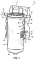
- Filter assembly 10 includes a filter 12 and a support bracket 14 with sidewalls 16. Filter 12 and bracket 14 have a quick attachment feature as will be described below.
- filter 12 includes an outer cup-shaped canister or housing 18 with an open upper end 20 and a closed lower end 22.
- a drain 23 ( Figure 3 ) can be located in a threaded opening 24 in the lower end of the housing to allow periodic removal of water from the filter.
- Canister has a generally cylindrical shape, although it can be other shapes; and can be formed from material appropriate for the particular application, such as plastic or metal.
- End cap 28 is attached such as by adhesive, welding or other bonding means to the upper end of the canister.
- End cap 28 includes an inlet port or tube 30 with an internal opening 31 to direct fluid to be filtered into the canister; and an outlet port or tube 32 with an internal opening 33 to direct filtered fluid out of the canister.
- a filter element 34 is centrally located in the canister, and has a ring-shaped configuration circumscribing a central cavity 35.
- Element 34 includes a lower circular end cap 36 sealingly bonded to the lower end of the media ring, while the upper end of the element is sealingly bonded directly to the end cap 28.
- Filter element 34 can have a structure (e.g., pleated, fibrous, etc) and be made from a material (e.g., cellulose, polymer) which is appropriate for the particular application, and likewise can have a geometry other than ring-shaped if so desired. While an element is shown and described which cannot be removed from the canister when spent, or in other words, the entire canister must be disposed of when the element becomes spent; it is also anticipated that the canister could have a removable upper end cap which would provide access to the element in the housing to enable replacement. Such a structure enabling removal of the element (e.g., threads) should be well-known to those skilled in the art.
- fluid entering inlet port 30 flows into a peripheral annular region 38 between the element and the inside surface of the housing, where the fluid then flows radially inward through the element where particulate matter and other contaminants are removed, and into the central cavity 35.
- the element has hydrophobic properties, water collecting on the outer surface of the element can agglomerate, and drip downward into the lower portion of the housing where it can be removed through drain opening 24.
- outlet port 32 The fluid then flow axially upward and outward through outlet port 32 to return to the fluid system. It is also anticipated that the flow through the element could be in the reverse direction; that is into port 32 and out of port 30, and travel radially outward through the media. It should also be appreciated that the inlet and outlet ports could alternatively be formed in other areas of the filter canister, such as in the sides, or in the bottom area.
- filter 12 includes structure which enables the filter to be quickly and easily attached to and removed from bracket 14.
- a pair of identical, radially-outward projecting rigid pivots are provided on the outer surface of the canister, on opposite sides thereof, between about the midpoint and the lower end of the canister.
- Pivots 40 each comprise a short, axially-extending base 41, and an enlarged circular head 42 projecting radially outwardly toward the lower end of the base.
- Head 42 includes a flat outer surface 46, and an inwardly-tapered or angled lower surface 48 which forms a lip around the head and interconnects the head 42 to the base 41.
- Pivots 40 each have a surface extension 50 which is interconnected to head 42 and is flush (co-planar) with surface 42; that is, surface extension 50 has the same outer dimension as head 42.
- the sides of the surface extension 50 are tapered or angled as at 51, and each surface extension extends axially a short distance along the side surface of the canister toward the open end of the canister from head 42.
- surface extension 50 of base 41 provides a stand-off against the sidewalls 16 of bracket 14 when the filter is mounted to the bracket.
- a series of angled or tapered ridges as at 54 are provided on either side of base 41, in axially spaced apart relation and extending in the circumferential direction, that is, perpendicular to the axial extend of the canister, to facilitate locating the filter within bracket 14.
- Ridges 54 have an outer dimension such that the ridges can engage the inside surface of the sidewalls of the bracket and help direct the filter between the sidewalls as the filter is mounted to the bracket.
- One of the ridges 55 has a greater radial projection, in other words, it projects radially outward further than the others, and serves as a locating and supporting ridge for the filter in the bracket, as will be discussed in greater detail below.
- Base 41, head 42 and ridges 54 can all be formed in one piece with the canister during the forming of the canister; or alternatively can be formed in one or more separate pieces and attached to each other and/or to the canister such as with adhesive or other bonding techniques.
- the attachment structure further includes a pair of flexible retaining clips as at 58, also provided on the outer surface of the canister, on opposite sides thereof, between about the midpoint and the upper end of the canister.
- Clips 58 are each in general axial alignment with a respective pivot 40, and can be spaced axially therefrom.
- Each retaining clip includes a thin, flexible, axially-extending body portion 60, in generally parallel relation to the outer surface of the canister, and connected at a base end 62 to the canister, and extending axially to a free head end 64 spaced radially-outward from the canister.
- the free end 64 of the clips can be flexibly bent toward the canister by appropriate manual manipulation of the clip.
- a release tab 66 with a flat outer surface is provided at the head end of the clip to facilitate this manipulation, and projects generally perpendicular to the extent of the body portion 60.
- a radial projection 68 is provided in generally the middle of each tab 66, and extends generally a short distance along the axis of the clip. Radial projection 68 enables the retaining clip to lock to a respective sidewall of the bracket, and hence retain the filter on the bracket, as will be described below.
- a radial stand-off 72 is provided in axially-spaced relation to each tab 66, between the tab and the upper end of the canister, and projecting radially outward about the same radial distance as tab 66 (minus the projection).
- stand-offs 72 prevent sidewalls 16 of bracket 14 from bending clips 60 completely against the surface of the canister, that is, the free ends of the clips remain somewhat spaced from the outer surface of the canister even after the filter is mounted on the bracket, such that the clips can be manipulated when it is desired to release the filter from its locked position with the bracket, as again, will be described more fully below.
- Clips 58, tab 66 and standoffs 72 also can all be formed in one piece with the canister during the forming of the canister; or alternatively can be formed in one or more separate pieces and attached to each other and/or to the canister such as with adhesive or other bonding techniques.
- the bracket 14 includes a flat body 79 with apertures 80 or other means to attach the bracket to an appropriate support surface, such as an engine block, or engine compartment.
- the sidewalls 16 of the bracket are each spaced apart from each other along opposite sides of body 79, and run generally parallel to each other and perpendicular to the body 79. The spacing of sidewalls 16 is such that the filter canister can be generally closely received between them.
- Sidewalls 16 each include a hook-shaped slot, as at 84, along the side edge of the sidewall and toward the lower end thereof, and opening generally toward the upper end of the bracket.
- the sidewall has a tapered or rounded surface 86 around the lower edge of each slot, and a tapered or rounded surface 87 around the upper edge of each slot, and the opening is dimensioned to receive the base 41 of the pivot ( Figure 4 ) in the area under the head 42.
- a thin slot 88 is provided axially upward from opening 84, and extends from the side edge of the sidewall inwardly toward the body 79, that is, horizontally relative to the longitudinal axis of the body. Slot 88 provides some flexibility to allow the sidewalls to bend and closely receive the filter as the filter is mounted to the bracket.
- the sidewalls generally conform as the ridges 54, and in particular locating ridge 55, are received between the sidewall as the filter is pivoted into its assembled position with the bracket.
- An axial slot 90 or other appropriate geometry such as a ridge, is next provided axially upward from the slot 88 on the sidewalls toward the upper end of the bracket sidewalls, with slot 90 dimensioned to receive the projection 68 ( Figure 4 ) on the tab of the clip.
- the slot 90 or other geometry provides a catch which retains the upper end of the filter to the bracket when the filter is mounted to the bracket, as will be described below.
- each sidewall includes a rounded cut-out shoulder portion 92 which is generally dimensioned and located to receive the inlet and outlet ports 30, 31 ( Figure 1 ) of the upper end cap when the filter is mounted to the filter head.
- the filter is initially inserted into the bracket such that the pivots 40 are each received in a respective slot 84.
- the slot 84 receives the base of the pivot, and the filter can pivot around this support while the filter is being mounted to the bracket, that is, as the filter is being brought into axial alignment with and substantially flush against the body of the bracket.
- the tapered inner lip surface of each head 42 and the tapered or rounded lower surface of the corresponding slot 84 facilitates locating the pivots with the slots.
- the extended locating ridge 55 on the base of each pivot guides the filter between the sidewalls 16.
- the base projection 50 then engages the inside surface of the sidewalls as the tapered sides 51 of the projection pass inwardly against the rounded upper surface 87 of the slot 84 (in effect pushing the sidewalls outwardly); and, along with the head 42 being closely received and supported by the rounded edges 86 on the lower portion of the slot 84 (in effect pulling the sidewalls inwardly), the lower end of the filter is thereby securely held on the bracket when the filter is completely mounted to the bracket (e.g., as shown in Figure 1 ).
- the retaining clips 58 on the filter are received between the sidewalls, and projections 68 engages the sidewalls, and force the clips slightly inwardly until the projections pass into the corresponding slots 90 in the sidewalls.
- Tabs 66 remain accessible and project outwardly from the sidewalls of the bracket.
- Stand-offs 72 adjacent the clips keep the upper end of the filter properly centred between the sidewalls and prevent the sidewalls from bending each clip flat against the canister.
- the filter can be supported against the body of the bracket, although it can also be held a small distance outwardly therefrom, as the connection with the pivots 40, including the locating ridges 55, and with the retaining clips 58, securely hold the filter to the bracket irrespective of whether the filter is supported against the body.
- Hoses can then be connected to the inlet port 30 and outlet port 32 of the filter to fluidly connect the filter within the fluid system.
- the hoses can be removed, and the tabs 66 of the clips can be accessed and inwardly depressed to move the projections 68 out of engagement with slots 90, and allow the filter to be pivoted into the Figure 6 position, where it can then be lifted upwardly and outwardly from the bracket.
- the pivots 40 are generally located on the filter canister such that the filter can be pivoted sufficiently without interference from the end of the canister bottoming against the bracket or adjacent support surface.
- the stand-offs 72 of the retaining clips keep the clips at a distance from the canister, such that they can be later depressed to allow detachment of the filter from the bracket.
- bracket While the filter has been described above being mounted to a stand-alone bracket, and the bracket is then mounted to an appropriate location such as to an engine block or engine compartment, it should be appreciated that such bracket could be incorporated as an integral part of the engine or compartment, or other support surface. In such case, the body of the bracket could be a portion of the engine, engine compartment or other support surface.
- attachment structure above has been described as including the combination of the pivots 40 including an enlarged head 42 with lip 48, and extension 50, ridges 54 and locating ridge 55; and retaining clips 58 including tabs 66 and projections 68, it should be appreciated that one or more of these components on the pivots and/or the retaining clips could be absent on one or both sides of the filter, and the filter 12 could still be mounted to the bracket 14.
Landscapes
- Chemical & Material Sciences (AREA)
- Chemical Kinetics & Catalysis (AREA)
- Lubrication Details And Ventilation Of Internal Combustion Engines (AREA)
- Filtration Of Liquid (AREA)
- Clamps And Clips (AREA)
Claims (15)
- Ein Filter (12), das ein in ein Gehäuse (18) eingeschlossenes Filterelement (34) umfasst, wobei das Gehäuse (18) eine Einlassöffnung (30) und eine Auslassöffnung (32) aufweist, um Fluid in das Gehäuse hinein und aus dem Gehäuse heraus zu leiten, wobei das Filtergehäuse ein Paar nach außen hinausragende Zapfen (40) umfasst, die an gegenüberliegende Seiten des Gehäuses (18) in Richtung dessen einen Endes (22) angeordnet sind und dazu verwendet werden können, das Gehäuse an einer Halterung (14) zu befestigen,
dadurch gekennzeichnet, dass das Gehäuse ein Paar flexible Halteklammern (58) aufweist, die ebenfalls an gegenüberliegende Seiten des Gehäuses in Richtung dessen anderen Endes (20) angeordnet sind, wobei jede Klammer (58) entlang der Länge des Gehäuses mit einem entsprechendem Zapfen (40) im Wesentlichen axial fluchtet, und die mit den Zapfen (40) zusammenarbeiten, um zu ermöglichen, dass das Gehäuse (18) an der Halterung (14) befestigt wird. - Das Filter (12) nach Anspruch 1, wobei jeder Zapfen (40) einen Sockel (41) und einen vergrößerten Kopf (42) aufweist, wobei der Kopf (42) eine unterseitig abgeschrägte Oberfläche (48) umfasst, die eine Lippe ausbildet.
- Das Filter (12) nach Anspruch 2, wobei der Sockel (41) eine Verlängerung (50) aufweist, die einen Vorsprung definiert und die koplanar zu einer äußeren Oberfläche (46) des Kopfes (42) aus dem Gehäuse (18) nach außen hinausragt.
- Das Filter (12) nach Anspruch 1, wobei jeder Zapfen (40) eine Positionierrippe (54) aufweist, der sich in einer zu der axialen Erstreckung des Gehäuses (18) senkrechten Richtung erstreckt.
- Das Filter (12) nach Anspruch 1, wobei jede Halteklammer (58) einen flexiblen, sich axial erstreckenden Körperabschnitt (60), und einen fest verbundenen senkrecht zu dem Körperabschnitt hinausragenden Laschenabschnitt (66) aufweist.
- Das Filter (12) nach Anspruch 5, wobei jeder Laschenabschnitt (66) ferner einen Vorsprung (68) aufweist, der aus einer Oberfläche des Laschenabschnitts hinausragt.
- Das Filter (12) nach einem der Ansprüche 5 oder 6, wobei jede Halteklammer (58) sich aus einem Sockelende (62), das in Richtung des einen Endes (22) des Gehäuses angebunden ist, hin zu einem freien Kopfende (64) in Richtung des anderen Endes (20) des Gehäuses erstreckt, und wobei der Laschenabschnitt (66) an dem Kopfende (64) der Halteklammer (58) angeordnet ist.
- Das Filter (12) nach Anspruch 7, der ferner einen nach außen hinausragenden Vorsprung (72) aufweist, der von jeder Halteklammer (58) axial beabstandet ist und derart dimensioniert ist, dass er die entsprechende Halteklammer (58) daran hindert, von einer Wand (16) einer Halterung (14) nach innen gegen das Gehäuse (18) gebogen zu werden.
- Das Filter (12) nach Anspruch 8, wobei der Vorsprung (72) von dem Kopfende (64) der Halteklammer in Richtung des anderen Endes des Gehäuses axial beabstandet ist.
- Eine Filterbaugruppe (10), die das Filter (12) nach einem der hervorgehenden Ansprüche und eine Stützhalterung (14) umfasst, wobei die Stützhalterung (14) einen longitudinalen Körperabschnitt (79) und ein Paar Seitenwände (16) umfasst, die nach außen aus dem Körper (79) beabstandet voneinander hinausragen, sodass das Filter (12) zwischen ihnen engsitzend aufgenommen werden kann, wobei jede der Seitenwände (16) aufweist:i) einen hakenförmigen Schlitz (84), der derart dimensioniert ist, dass er einen entsprechenden Zapfen (40) am Filter (12) aufnimmt und dem Filter (12) erlaubt, von einer Orientierung unter einem Winkel zu der longitudinalen Achse der Halterung (14) zu einer Orientierung zu schwenken, in der das Filter mit der Halterung (14) im Wesentlichen axial ausgerichtet ist; undii) eine Raste (90), die derart dimensioniert ist, dass sie eine entsprechende Halteklammer (58) aufnimmt und festhält, wenn das Filter (12) mit der Halterung (14) im Wesentlichen axial ausgerichtet ist.
- Die Filterbaugruppe (10) nach Anspruch 10, wobei jeder Zapfen einen Sockel (41) und einen vergrößerten Kopf (42) aufweist, wobei der Kopf (42) eine unterseitig abgeschrägte Oberfläche (48) umfasst, die eine Lippe definiert, und wobei der hakenförmigen Schlitz (84) eine entsprechend abgeschrägte Oberfläche (87) aufweist, wobei die abgeschrägte Oberfläche (48) des Kopfes (42) derart dimensioniert ist, dass sie gegen die abgeschrägte Oberfläche (87) des Schlitzes (84) schwenkt.
- Die Filterbaugruppe (10) nach einem der Ansprüche 10 oder 11, wobei jeder Sockel eine Verlängerung (50) mit einer äußeren Oberfläche, die mit einer äußeren Oberfläche (46) des Kopfes (42) verbunden und fluchtend ist, aufweist, wobei die Verlängerungen (50) derart dimensioniert sind, dass sie zwischen den Seitenwänden (16) der Halterung (14) engsitzend aufgenommen werden.
- Die Filterbaugruppe (10) nach einem der Ansprüche 10 -12, wobei jeder Zapfen (40) eine Positionierrippe (55) aufweist, der sich in einer Umfangsrichtung von dem Sockel (41) erstreckt, wobei die Fixierkämme (55) dazu ausgelegt sind, das Gehäuse (18) zwischen den Seitenwänden (16) zu führen, wenn das Filter (12) zu der Halterung (14) ausgerichtet wird.
- Die Filterbaugruppe (10) nach einem der Ansprüche 10 -13, wobei jede Halteklammer (58) einen flexiblen, sich axial erstreckenden Körperabschnitt (60) und einen fest verbundenen senkrecht zu dem Körperabschnitt hinausragenden Laschenabschnitt (66) aufweist, wobei jeder Laschenabschnitt (66) einen Vorsprung (68) aufweist, der aus einer Oberfläche des Laschenabschnitts (66) radial nach außen hinausragt, wobei der Vorsprung (68) an jedem Laschenabschnitt (66) dazu ausgelegt ist, mit der Raste (90) zusammenzuarbeiten, um das Filter (12) mit der Halterung zu verriegeln, wenn das Filter (12) mit der Halterung (14) im Wesentlichen axial ausgerichtet ist.
- Die Filterbaugruppe (10) nach Anspruch 14, die ferner einen nach außen hinausragenden Vorsprung (72) aufweist, der von jeder Halteklammer (58) axial beabstandet ist und derart dimensioniert ist, dass er die entsprechende Halteklammer (58) daran hindert, von einer Wand (16) einer Halterung (14) nach innen gegen das Gehäuse (18) gebogen zu werden, wenn das Filter (12) mit der Halterung (14) verriegelt wird.
Applications Claiming Priority (2)
| Application Number | Priority Date | Filing Date | Title |
|---|---|---|---|
| US12/472,668 US8043503B2 (en) | 2009-05-27 | 2009-05-27 | Filter with quick attachment features |
| PCT/US2010/031350 WO2010138252A1 (en) | 2009-05-27 | 2010-04-16 | Filter with quick attachment features |
Publications (2)
| Publication Number | Publication Date |
|---|---|
| EP2435159A1 EP2435159A1 (de) | 2012-04-04 |
| EP2435159B1 true EP2435159B1 (de) | 2016-03-23 |
Family
ID=42245583
Family Applications (1)
| Application Number | Title | Priority Date | Filing Date |
|---|---|---|---|
| EP10714810.8A Active EP2435159B1 (de) | 2009-05-27 | 2010-04-16 | Filter mit schnellbefestigungsmerkmalen |
Country Status (7)
| Country | Link |
|---|---|
| US (1) | US8043503B2 (de) |
| EP (1) | EP2435159B1 (de) |
| JP (1) | JP5643299B2 (de) |
| KR (1) | KR101659962B1 (de) |
| CN (1) | CN102448575B (de) |
| BR (1) | BRPI1012089B1 (de) |
| WO (1) | WO2010138252A1 (de) |
Cited By (1)
| Publication number | Priority date | Publication date | Assignee | Title |
|---|---|---|---|---|
| WO2018153435A1 (en) | 2017-02-21 | 2018-08-30 | Mahle International Gmbh | Fuel filter device for an internal combustion engine |
Families Citing this family (19)
| Publication number | Priority date | Publication date | Assignee | Title |
|---|---|---|---|---|
| WO2010138261A1 (en) | 2009-05-27 | 2010-12-02 | Parker-Hannifin Corporation | Priming method for filter |
| US8695940B2 (en) | 2009-07-09 | 2014-04-15 | Cummins Filtration Ip, Inc. | Mounting interface for a housing of a filtration module |
| JP2013230410A (ja) * | 2012-04-27 | 2013-11-14 | Sharp Corp | 液体濾過器 |
| JP5884660B2 (ja) * | 2012-07-03 | 2016-03-15 | 三菱自動車工業株式会社 | 燃料フィルターのブラケット |
| US9675908B2 (en) | 2013-01-14 | 2017-06-13 | Clarcor Engine Mobile Solutions, Llc | Fuel filter assembly and cartridge |
| US9550135B2 (en) | 2013-01-14 | 2017-01-24 | Clarcor Engine Mobile Solutions, Llc | Fuel filter assembly and cartridge |
| US9421489B2 (en) | 2013-06-24 | 2016-08-23 | Parker-Hannifin Corporation | Diesel fuel and urea tank air breather filter |
| CN104234894B (zh) * | 2014-07-22 | 2016-09-07 | 安徽江淮汽车股份有限公司 | 一种滤清器泵油辅助机构总成 |
| DE102014019425A1 (de) | 2014-12-20 | 2016-06-23 | Man Diesel & Turbo Se | Ansauganordnung |
| US9669337B2 (en) * | 2015-03-11 | 2017-06-06 | GL&V Luxembourg Sàrl | Method of constructing a rotary drum filtering apparatus |
| US11278829B2 (en) * | 2017-08-11 | 2022-03-22 | King Technology Inc | Filterwell cartridge holder |
| US11536466B2 (en) * | 2018-10-04 | 2022-12-27 | Johnson Controls Tyco IP Holdings LLP | Systems and methods for gas valve assembly of an HVAC system |
| EP3643386B1 (de) | 2018-10-23 | 2024-02-21 | Volvo Car Corporation | Verbessertes ölfilter |
| US10828586B2 (en) * | 2018-10-26 | 2020-11-10 | Haier Us Appliance Solutions, Inc. | Filter assembly for a refrigerator appliance |
| EP3938598A4 (de) * | 2019-03-15 | 2022-12-28 | King Technology, Inc. | Halter für filtervertiefungskassetten |
| FR3113607B1 (fr) * | 2020-08-27 | 2022-08-05 | Psa Automobiles Sa | Systeme de filtre a carburant a goupille de securite |
| FR3113845B1 (fr) * | 2020-09-07 | 2023-04-21 | Psa Automobiles Sa | Systeme de filtre a carburant a agrafe de securite |
| EP4011482A1 (de) * | 2020-12-14 | 2022-06-15 | KNORR-BREMSE Systeme für Nutzfahrzeuge GmbH | Trockenmittelbehälter, lufttrocknerkartusche, luftbehandlungsvorrichtung und verfahren zur herstellung eines trockenmittelbehälters |
| USD1036623S1 (en) * | 2024-03-02 | 2024-07-23 | Brio Water Technology, Inc. | Filter rack |
Family Cites Families (14)
| Publication number | Priority date | Publication date | Assignee | Title |
|---|---|---|---|---|
| JPS5970074U (ja) * | 1982-11-04 | 1984-05-12 | 加藤発条株式会社 | 燃料用フイルタ−の保持装置 |
| IT232410Y1 (it) | 1994-05-24 | 1999-12-17 | Dayco Europe Spa | Dispositivo filtrante per il recuoero dei vapori derivanti dal carburante di un veicolo. |
| JP3824134B2 (ja) * | 2000-12-04 | 2006-09-20 | 本田技研工業株式会社 | ハウジング |
| TWI269665B (en) * | 2002-02-21 | 2007-01-01 | Roger P Reid | Quick change filter and bracket system with key system and universal key option |
| US6966940B2 (en) * | 2002-04-04 | 2005-11-22 | Donaldson Company, Inc. | Air filter cartridge |
| FR2845081B1 (fr) * | 2002-09-26 | 2006-04-28 | Millipore Corp | Ensemble a module de traitement de fluide et structure de support ayant des surfaces fonctionnelles cooperantes perfectionnees, ainsi que module et appareil correspondants |
| JP3875623B2 (ja) | 2002-11-06 | 2007-01-31 | インテグリス・インコーポレーテッド | フィルタ装置 |
| US7395936B2 (en) * | 2003-02-26 | 2008-07-08 | Parker-Hannifin Corporation | Filter element with vent orifice and assembly therefore |
| CN100389851C (zh) * | 2003-03-06 | 2008-05-28 | 安格斯公司 | 过滤装置 |
| US20060032806A1 (en) * | 2004-08-16 | 2006-02-16 | Parker Mark A | Apparatus to filter water |
| KR100712266B1 (ko) * | 2005-03-24 | 2007-05-17 | 주식회사 피코그램 | 커넥터를 이용하여 용이하게 교체되는 정수용 필터, 및 이를 이용한 정수장치 |
| US8801925B2 (en) * | 2006-02-09 | 2014-08-12 | Emd Millipore Corporation | Filter alignment device |
| US20100065484A1 (en) * | 2006-11-07 | 2010-03-18 | Koninklijke Philips Electronics N.V. | Water purification device and filter unit |
| DE202007012690U1 (de) * | 2007-09-11 | 2009-02-05 | Mann+Hummel Gmbh | Filtereinrichtung |
-
2009
- 2009-05-27 US US12/472,668 patent/US8043503B2/en active Active
-
2010
- 2010-04-16 WO PCT/US2010/031350 patent/WO2010138252A1/en not_active Ceased
- 2010-04-16 BR BRPI1012089-0A patent/BRPI1012089B1/pt active IP Right Grant
- 2010-04-16 KR KR1020117030468A patent/KR101659962B1/ko active Active
- 2010-04-16 JP JP2012513077A patent/JP5643299B2/ja active Active
- 2010-04-16 CN CN201080023058.8A patent/CN102448575B/zh active Active
- 2010-04-16 EP EP10714810.8A patent/EP2435159B1/de active Active
Cited By (1)
| Publication number | Priority date | Publication date | Assignee | Title |
|---|---|---|---|---|
| WO2018153435A1 (en) | 2017-02-21 | 2018-08-30 | Mahle International Gmbh | Fuel filter device for an internal combustion engine |
Also Published As
| Publication number | Publication date |
|---|---|
| KR101659962B1 (ko) | 2016-09-26 |
| US8043503B2 (en) | 2011-10-25 |
| JP5643299B2 (ja) | 2014-12-17 |
| BRPI1012089B1 (pt) | 2020-03-17 |
| US20100300952A1 (en) | 2010-12-02 |
| BRPI1012089A2 (pt) | 2019-04-02 |
| JP2012528003A (ja) | 2012-11-12 |
| KR20120030435A (ko) | 2012-03-28 |
| EP2435159A1 (de) | 2012-04-04 |
| CN102448575A (zh) | 2012-05-09 |
| WO2010138252A1 (en) | 2010-12-02 |
| CN102448575B (zh) | 2014-09-03 |
Similar Documents
| Publication | Publication Date | Title |
|---|---|---|
| US8043503B2 (en) | Filter with quick attachment features | |
| EP2435107B1 (de) | Primingverfahren für einen filter | |
| KR101768835B1 (ko) | 가스상 유체를 여과하기 위한 필터 유닛 | |
| AU719225B2 (en) | Self-evacuating water-separating fuel filter | |
| US8128817B2 (en) | Liquid filter suitable for motor vehicles | |
| US8043504B2 (en) | Filter cartridge | |
| EP4122576B1 (de) | Filtersystem mit gehäuse und filterelement | |
| US8999163B2 (en) | Top load liquid filter assembly, system and methods | |
| CN109890479B (zh) | 用于过滤器的面部密封系统 | |
| US20100294707A1 (en) | Multi-stage filter cartridge with snap fit filters | |
| US20100193417A1 (en) | Exchangeable Filter | |
| JPH03157109A (ja) | 燃料フィルタ組立体及び燃料フィルタカートリッジ | |
| US20190046904A1 (en) | A filter insert and a filter arrangement | |
| US20200284228A1 (en) | Filter Arrangement | |
| WO1991003301A1 (en) | Fuel filter | |
| JP2004538133A (ja) | ドレーンパイプを備えたフィルタエレメント | |
| JP2005248945A (ja) | エンジンフィルタ又はトランスミッションフィルタにおけるフィルタ媒体の支持装置又は方法 |
Legal Events
| Date | Code | Title | Description |
|---|---|---|---|
| PUAI | Public reference made under article 153(3) epc to a published international application that has entered the european phase |
Free format text: ORIGINAL CODE: 0009012 |
|
| 17P | Request for examination filed |
Effective date: 20111102 |
|
| AK | Designated contracting states |
Kind code of ref document: A1 Designated state(s): AT BE BG CH CY CZ DE DK EE ES FI FR GB GR HR HU IE IS IT LI LT LU LV MC MK MT NL NO PL PT RO SE SI SK SM TR |
|
| DAX | Request for extension of the european patent (deleted) | ||
| GRAP | Despatch of communication of intention to grant a patent |
Free format text: ORIGINAL CODE: EPIDOSNIGR1 |
|
| INTG | Intention to grant announced |
Effective date: 20150806 |
|
| GRAS | Grant fee paid |
Free format text: ORIGINAL CODE: EPIDOSNIGR3 |
|
| GRAA | (expected) grant |
Free format text: ORIGINAL CODE: 0009210 |
|
| INTG | Intention to grant announced |
Effective date: 20160125 |
|
| AK | Designated contracting states |
Kind code of ref document: B1 Designated state(s): AT BE BG CH CY CZ DE DK EE ES FI FR GB GR HR HU IE IS IT LI LT LU LV MC MK MT NL NO PL PT RO SE SI SK SM TR |
|
| REG | Reference to a national code |
Ref country code: GB Ref legal event code: FG4D |
|
| REG | Reference to a national code |
Ref country code: CH Ref legal event code: EP |
|
| REG | Reference to a national code |
Ref country code: AT Ref legal event code: REF Ref document number: 782561 Country of ref document: AT Kind code of ref document: T Effective date: 20160415 |
|
| REG | Reference to a national code |
Ref country code: IE Ref legal event code: FG4D |
|
| REG | Reference to a national code |
Ref country code: FR Ref legal event code: PLFP Year of fee payment: 7 |
|
| REG | Reference to a national code |
Ref country code: DE Ref legal event code: R096 Ref document number: 602010031395 Country of ref document: DE |
|
| REG | Reference to a national code |
Ref country code: LT Ref legal event code: MG4D |
|
| REG | Reference to a national code |
Ref country code: NL Ref legal event code: MP Effective date: 20160323 |
|
| PG25 | Lapsed in a contracting state [announced via postgrant information from national office to epo] |
Ref country code: FI Free format text: LAPSE BECAUSE OF FAILURE TO SUBMIT A TRANSLATION OF THE DESCRIPTION OR TO PAY THE FEE WITHIN THE PRESCRIBED TIME-LIMIT Effective date: 20160323 Ref country code: HR Free format text: LAPSE BECAUSE OF FAILURE TO SUBMIT A TRANSLATION OF THE DESCRIPTION OR TO PAY THE FEE WITHIN THE PRESCRIBED TIME-LIMIT Effective date: 20160323 Ref country code: GR Free format text: LAPSE BECAUSE OF FAILURE TO SUBMIT A TRANSLATION OF THE DESCRIPTION OR TO PAY THE FEE WITHIN THE PRESCRIBED TIME-LIMIT Effective date: 20160624 Ref country code: NO Free format text: LAPSE BECAUSE OF FAILURE TO SUBMIT A TRANSLATION OF THE DESCRIPTION OR TO PAY THE FEE WITHIN THE PRESCRIBED TIME-LIMIT Effective date: 20160623 |
|
| REG | Reference to a national code |
Ref country code: AT Ref legal event code: MK05 Ref document number: 782561 Country of ref document: AT Kind code of ref document: T Effective date: 20160323 |
|
| PG25 | Lapsed in a contracting state [announced via postgrant information from national office to epo] |
Ref country code: SE Free format text: LAPSE BECAUSE OF FAILURE TO SUBMIT A TRANSLATION OF THE DESCRIPTION OR TO PAY THE FEE WITHIN THE PRESCRIBED TIME-LIMIT Effective date: 20160323 Ref country code: LV Free format text: LAPSE BECAUSE OF FAILURE TO SUBMIT A TRANSLATION OF THE DESCRIPTION OR TO PAY THE FEE WITHIN THE PRESCRIBED TIME-LIMIT Effective date: 20160323 Ref country code: NL Free format text: LAPSE BECAUSE OF FAILURE TO SUBMIT A TRANSLATION OF THE DESCRIPTION OR TO PAY THE FEE WITHIN THE PRESCRIBED TIME-LIMIT Effective date: 20160323 Ref country code: BE Free format text: LAPSE BECAUSE OF NON-PAYMENT OF DUE FEES Effective date: 20160430 Ref country code: LT Free format text: LAPSE BECAUSE OF FAILURE TO SUBMIT A TRANSLATION OF THE DESCRIPTION OR TO PAY THE FEE WITHIN THE PRESCRIBED TIME-LIMIT Effective date: 20160323 |
|
| PG25 | Lapsed in a contracting state [announced via postgrant information from national office to epo] |
Ref country code: PL Free format text: LAPSE BECAUSE OF FAILURE TO SUBMIT A TRANSLATION OF THE DESCRIPTION OR TO PAY THE FEE WITHIN THE PRESCRIBED TIME-LIMIT Effective date: 20160323 Ref country code: EE Free format text: LAPSE BECAUSE OF FAILURE TO SUBMIT A TRANSLATION OF THE DESCRIPTION OR TO PAY THE FEE WITHIN THE PRESCRIBED TIME-LIMIT Effective date: 20160323 Ref country code: IS Free format text: LAPSE BECAUSE OF FAILURE TO SUBMIT A TRANSLATION OF THE DESCRIPTION OR TO PAY THE FEE WITHIN THE PRESCRIBED TIME-LIMIT Effective date: 20160723 |
|
| PG25 | Lapsed in a contracting state [announced via postgrant information from national office to epo] |
Ref country code: ES Free format text: LAPSE BECAUSE OF FAILURE TO SUBMIT A TRANSLATION OF THE DESCRIPTION OR TO PAY THE FEE WITHIN THE PRESCRIBED TIME-LIMIT Effective date: 20160323 Ref country code: SM Free format text: LAPSE BECAUSE OF FAILURE TO SUBMIT A TRANSLATION OF THE DESCRIPTION OR TO PAY THE FEE WITHIN THE PRESCRIBED TIME-LIMIT Effective date: 20160323 Ref country code: CZ Free format text: LAPSE BECAUSE OF FAILURE TO SUBMIT A TRANSLATION OF THE DESCRIPTION OR TO PAY THE FEE WITHIN THE PRESCRIBED TIME-LIMIT Effective date: 20160323 Ref country code: RO Free format text: LAPSE BECAUSE OF FAILURE TO SUBMIT A TRANSLATION OF THE DESCRIPTION OR TO PAY THE FEE WITHIN THE PRESCRIBED TIME-LIMIT Effective date: 20160323 Ref country code: SK Free format text: LAPSE BECAUSE OF FAILURE TO SUBMIT A TRANSLATION OF THE DESCRIPTION OR TO PAY THE FEE WITHIN THE PRESCRIBED TIME-LIMIT Effective date: 20160323 Ref country code: AT Free format text: LAPSE BECAUSE OF FAILURE TO SUBMIT A TRANSLATION OF THE DESCRIPTION OR TO PAY THE FEE WITHIN THE PRESCRIBED TIME-LIMIT Effective date: 20160323 Ref country code: PT Free format text: LAPSE BECAUSE OF FAILURE TO SUBMIT A TRANSLATION OF THE DESCRIPTION OR TO PAY THE FEE WITHIN THE PRESCRIBED TIME-LIMIT Effective date: 20160725 |
|
| REG | Reference to a national code |
Ref country code: CH Ref legal event code: PL |
|
| PG25 | Lapsed in a contracting state [announced via postgrant information from national office to epo] |
Ref country code: BE Free format text: LAPSE BECAUSE OF FAILURE TO SUBMIT A TRANSLATION OF THE DESCRIPTION OR TO PAY THE FEE WITHIN THE PRESCRIBED TIME-LIMIT Effective date: 20160323 |
|
| REG | Reference to a national code |
Ref country code: DE Ref legal event code: R097 Ref document number: 602010031395 Country of ref document: DE |
|
| REG | Reference to a national code |
Ref country code: IE Ref legal event code: MM4A |
|
| PLBE | No opposition filed within time limit |
Free format text: ORIGINAL CODE: 0009261 |
|
| STAA | Information on the status of an ep patent application or granted ep patent |
Free format text: STATUS: NO OPPOSITION FILED WITHIN TIME LIMIT |
|
| PG25 | Lapsed in a contracting state [announced via postgrant information from national office to epo] |
Ref country code: LI Free format text: LAPSE BECAUSE OF NON-PAYMENT OF DUE FEES Effective date: 20160430 Ref country code: CH Free format text: LAPSE BECAUSE OF NON-PAYMENT OF DUE FEES Effective date: 20160430 Ref country code: DK Free format text: LAPSE BECAUSE OF FAILURE TO SUBMIT A TRANSLATION OF THE DESCRIPTION OR TO PAY THE FEE WITHIN THE PRESCRIBED TIME-LIMIT Effective date: 20160323 |
|
| PG25 | Lapsed in a contracting state [announced via postgrant information from national office to epo] |
Ref country code: BG Free format text: LAPSE BECAUSE OF FAILURE TO SUBMIT A TRANSLATION OF THE DESCRIPTION OR TO PAY THE FEE WITHIN THE PRESCRIBED TIME-LIMIT Effective date: 20160623 |
|
| 26N | No opposition filed |
Effective date: 20170102 |
|
| REG | Reference to a national code |
Ref country code: FR Ref legal event code: PLFP Year of fee payment: 8 |
|
| PG25 | Lapsed in a contracting state [announced via postgrant information from national office to epo] |
Ref country code: SI Free format text: LAPSE BECAUSE OF FAILURE TO SUBMIT A TRANSLATION OF THE DESCRIPTION OR TO PAY THE FEE WITHIN THE PRESCRIBED TIME-LIMIT Effective date: 20160323 Ref country code: IE Free format text: LAPSE BECAUSE OF NON-PAYMENT OF DUE FEES Effective date: 20160416 |
|
| PG25 | Lapsed in a contracting state [announced via postgrant information from national office to epo] |
Ref country code: IT Free format text: LAPSE BECAUSE OF FAILURE TO SUBMIT A TRANSLATION OF THE DESCRIPTION OR TO PAY THE FEE WITHIN THE PRESCRIBED TIME-LIMIT Effective date: 20160323 |
|
| REG | Reference to a national code |
Ref country code: FR Ref legal event code: PLFP Year of fee payment: 9 |
|
| PG25 | Lapsed in a contracting state [announced via postgrant information from national office to epo] |
Ref country code: HU Free format text: LAPSE BECAUSE OF FAILURE TO SUBMIT A TRANSLATION OF THE DESCRIPTION OR TO PAY THE FEE WITHIN THE PRESCRIBED TIME-LIMIT; INVALID AB INITIO Effective date: 20100416 Ref country code: CY Free format text: LAPSE BECAUSE OF FAILURE TO SUBMIT A TRANSLATION OF THE DESCRIPTION OR TO PAY THE FEE WITHIN THE PRESCRIBED TIME-LIMIT Effective date: 20160323 |
|
| PG25 | Lapsed in a contracting state [announced via postgrant information from national office to epo] |
Ref country code: MK Free format text: LAPSE BECAUSE OF FAILURE TO SUBMIT A TRANSLATION OF THE DESCRIPTION OR TO PAY THE FEE WITHIN THE PRESCRIBED TIME-LIMIT Effective date: 20160323 Ref country code: LU Free format text: LAPSE BECAUSE OF NON-PAYMENT OF DUE FEES Effective date: 20160416 Ref country code: TR Free format text: LAPSE BECAUSE OF FAILURE TO SUBMIT A TRANSLATION OF THE DESCRIPTION OR TO PAY THE FEE WITHIN THE PRESCRIBED TIME-LIMIT Effective date: 20160323 Ref country code: MC Free format text: LAPSE BECAUSE OF FAILURE TO SUBMIT A TRANSLATION OF THE DESCRIPTION OR TO PAY THE FEE WITHIN THE PRESCRIBED TIME-LIMIT Effective date: 20160323 Ref country code: MT Free format text: LAPSE BECAUSE OF NON-PAYMENT OF DUE FEES Effective date: 20160430 |
|
| P01 | Opt-out of the competence of the unified patent court (upc) registered |
Effective date: 20230524 |
|
| PGFP | Annual fee paid to national office [announced via postgrant information from national office to epo] |
Ref country code: DE Payment date: 20250429 Year of fee payment: 16 |
|
| PGFP | Annual fee paid to national office [announced via postgrant information from national office to epo] |
Ref country code: GB Payment date: 20250428 Year of fee payment: 16 |
|
| PGFP | Annual fee paid to national office [announced via postgrant information from national office to epo] |
Ref country code: FR Payment date: 20250425 Year of fee payment: 16 |