EP2434298B1 - Movement condition detection device - Google Patents
Movement condition detection device Download PDFInfo
- Publication number
- EP2434298B1 EP2434298B1 EP10777646.0A EP10777646A EP2434298B1 EP 2434298 B1 EP2434298 B1 EP 2434298B1 EP 10777646 A EP10777646 A EP 10777646A EP 2434298 B1 EP2434298 B1 EP 2434298B1
- Authority
- EP
- European Patent Office
- Prior art keywords
- acceleration
- angle
- component
- attached angle
- moving state
- Prior art date
- Legal status (The legal status is an assumption and is not a legal conclusion. Google has not performed a legal analysis and makes no representation as to the accuracy of the status listed.)
- Active
Links
- 238000001514 detection method Methods 0.000 title description 15
- 230000001133 acceleration Effects 0.000 claims description 187
- 238000012545 processing Methods 0.000 claims description 40
- 230000005484 gravity Effects 0.000 claims description 26
- 238000012935 Averaging Methods 0.000 claims description 17
- 238000000034 method Methods 0.000 claims description 6
- 238000005259 measurement Methods 0.000 claims description 2
- 239000003795 chemical substances by application Substances 0.000 description 63
- 238000005070 sampling Methods 0.000 description 7
- 238000010586 diagram Methods 0.000 description 6
- 230000007704 transition Effects 0.000 description 6
- 239000011159 matrix material Substances 0.000 description 5
- 238000012937 correction Methods 0.000 description 4
- 239000013598 vector Substances 0.000 description 3
- 230000000694 effects Effects 0.000 description 2
- 230000002730 additional effect Effects 0.000 description 1
- 230000003139 buffering effect Effects 0.000 description 1
- 230000015556 catabolic process Effects 0.000 description 1
- 238000006243 chemical reaction Methods 0.000 description 1
- 238000006731 degradation reaction Methods 0.000 description 1
- 230000007774 longterm Effects 0.000 description 1
- 239000007787 solid Substances 0.000 description 1
Images


Classifications
-
- G—PHYSICS
- G01—MEASURING; TESTING
- G01P—MEASURING LINEAR OR ANGULAR SPEED, ACCELERATION, DECELERATION, OR SHOCK; INDICATING PRESENCE, ABSENCE, OR DIRECTION, OF MOVEMENT
- G01P21/00—Testing or calibrating of apparatus or devices covered by the preceding groups
-
- G—PHYSICS
- G01—MEASURING; TESTING
- G01C—MEASURING DISTANCES, LEVELS OR BEARINGS; SURVEYING; NAVIGATION; GYROSCOPIC INSTRUMENTS; PHOTOGRAMMETRY OR VIDEOGRAMMETRY
- G01C21/00—Navigation; Navigational instruments not provided for in groups G01C1/00 - G01C19/00
- G01C21/10—Navigation; Navigational instruments not provided for in groups G01C1/00 - G01C19/00 by using measurements of speed or acceleration
- G01C21/12—Navigation; Navigational instruments not provided for in groups G01C1/00 - G01C19/00 by using measurements of speed or acceleration executed aboard the object being navigated; Dead reckoning
- G01C21/16—Navigation; Navigational instruments not provided for in groups G01C1/00 - G01C19/00 by using measurements of speed or acceleration executed aboard the object being navigated; Dead reckoning by integrating acceleration or speed, i.e. inertial navigation
- G01C21/183—Compensation of inertial measurements, e.g. for temperature effects
- G01C21/185—Compensation of inertial measurements, e.g. for temperature effects for gravity
-
- G—PHYSICS
- G01—MEASURING; TESTING
- G01C—MEASURING DISTANCES, LEVELS OR BEARINGS; SURVEYING; NAVIGATION; GYROSCOPIC INSTRUMENTS; PHOTOGRAMMETRY OR VIDEOGRAMMETRY
- G01C25/00—Manufacturing, calibrating, cleaning, or repairing instruments or devices referred to in the other groups of this subclass
- G01C25/005—Manufacturing, calibrating, cleaning, or repairing instruments or devices referred to in the other groups of this subclass initial alignment, calibration or starting-up of inertial devices
-
- G—PHYSICS
- G01—MEASURING; TESTING
- G01P—MEASURING LINEAR OR ANGULAR SPEED, ACCELERATION, DECELERATION, OR SHOCK; INDICATING PRESENCE, ABSENCE, OR DIRECTION, OF MOVEMENT
- G01P15/00—Measuring acceleration; Measuring deceleration; Measuring shock, i.e. sudden change of acceleration
- G01P15/02—Measuring acceleration; Measuring deceleration; Measuring shock, i.e. sudden change of acceleration by making use of inertia forces using solid seismic masses
- G01P15/08—Measuring acceleration; Measuring deceleration; Measuring shock, i.e. sudden change of acceleration by making use of inertia forces using solid seismic masses with conversion into electric or magnetic values
- G01P15/0802—Details
Definitions
- the present invention relates to a moving state detecting device that is attached in a moving body and detects a moving state such as a speed and a pitch angle of the moving body.
- a position of the device itself is detected based on positioning signals from positioning satellites, such as GPS satellites, and a moving state of a movable body is detected by using speed information that the movable body already has, such as a vehicle speed pulse in an automobile, and azimuth information that is obtained by, for example, a gyroscope.
- an attached angle calculating device such as the one disclosed in either one of Patent Documents 1 and 2 is installed in the navigation apparatus, the attached angle of the accelerometer is calculated, and an acceleration is corrected.
- the document WO2006/103246 describes a digital high-pass filter for operating on the output of an accelerometer in order to eliminate continuous components of acceleration signals which may be linked to acceleration due to gravity.
- the attached angle calculating devices disclosed in the Patent Documents 1 and 2 described above are not for detecting the attached angle only from an output value of the accelerometer but for detecting by using, for example, an angular velocity obtained from a gyroscope or an angular rate sensor, and a vehicle speed pulse obtained from the movable body.
- the acceleration that is outputted from the accelerometer contains unnecessary components such as a bias component and a noise component, these components are not taken into consideration here. Therefore, because the attached angle of the accelerometer is calculated using the acceleration containing an error due to the bias component and the noise component, the attached angle cannot accurately be calculated. Thus, the acceleration obtained from the accelerometer cannot accurately be corrected and the traveling speed and the traveling azimuth of the movable body cannot correctly be obtained.
- An object of the present invention is to realize a moving state detecting device for removing influence of unnecessary components, such as a bias component and a noise component, contained in an acceleration that is outputted from an accelerometer, calculating an attached angle of the accelerometer, and thereby, accurately correcting the acceleration obtained from the accelerometer.
- a moving state detecting device is provided as defined in claim 1.
- the moving state detecting device of this invention may include the accelerometer and the acceleration correcting module.
- the accelerometer may be installed in the movable body and calculate the acceleration of the movable body.
- the acceleration correcting module may divide, for every frequency band sequentially from a low frequency side, the acceleration obtained from the accelerometer into a bias frequency component, the gravity frequency component, the movement acceleration frequency component, and a noise frequency component, estimate the attached angle of the accelerometer based on the gravity frequency component and the movement acceleration frequency component, and correct the acceleration based on the attached angle.
- the acceleration that is obtained from the accelerometer is divided for every frequency band.
- the bias frequency component is a component that is substantially constantly outputted regardless of a moving state of the movable body and is formed by an extremely low range frequency.
- the noise frequency component is a component that continuously changes at random regardless of the moving state of the movable body and is formed by a high range frequency.
- the gravity frequency component and the movement acceleration frequency component depend on the moving state of the movable body, and since variations thereof are greater than the bias frequency component, these components have frequencies higher than the bias frequency component, and since these components do not have randomness more than the noise frequency component, they have frequencies lower than the noise frequency component.
- the acceleration correcting module of the moving state detecting device of this invention may frequency-divide the acceleration through a wavelet transform.
- the accelerometer of the moving state detecting device of this invention detects acceleration components with a front-and-rear direction acceleration component, a left-and-right direction acceleration component, and an up-and-down direction acceleration component, all of which are perpendicular to each other respectively.
- the acceleration correcting module can perform at least one of an estimation of an attached angle in an azimuth direction based on the front-and-rear direction acceleration component and the left-and-right direction acceleration component, an estimation of an attached angle in a pitch direction based on the front-and-rear direction acceleration component and the up-and-down direction acceleration component, and an estimation of an attached angle in a roll direction based on the front-and-rear direction acceleration component, the left-and-right direction acceleration component, the up-and-down direction acceleration component, and the pitch direction attached angle.
- the accelerometer of the moving state detecting device of this invention may detect acceleration components with a front-and-rear direction acceleration component, a left-and-right direction acceleration component, and an up-and-down direction acceleration component, all of which are perpendicular to each other respectively.
- the acceleration correcting module may estimate an attached angle in an azimuth direction based on the front-and-rear direction acceleration component and the left-and-right direction acceleration component, estimate an attached angle in a pitch direction based on the front-and-rear direction acceleration component and the up-and-down direction acceleration component, and estimate an attached angle in a roll direction based on the front-and-rear direction acceleration component, the left-and-right direction acceleration component, the up-and-down direction acceleration component, and the pitch direction attached angle.
- the acceleration correcting module of the moving state detecting device of this invention may estimate at least one of the azimuth direction attached angle and the pitch direction attached angle when the left-and-right direction acceleration component is below a predetermined threshold.
- the acceleration correcting module of the moving state detecting device of this invention estimates at least one of the azimuth direction attached angle and the pitch direction attached angle.
- the acceleration correcting module of the moving state detecting device of this invention may estimate the roll direction attached angle.
- the azimuth direction attached angle, the pitch direction attached angle, and the roll direction attached angle are estimated according to the transitions of the moving state of the movable body based on the left-and-right direction acceleration component.
- the acceleration correcting module of the moving state detecting device of this invention may sequentially store the estimated attached angle as well as calculate the attached angle through time averaging processing.
- the acceleration correcting module may reduce a weight of the previous attached angle in the time averaging processing.
- an error component of the estimated attached angle is suppressed.
- the traveling route is mostly a flat ground
- the error component due to the attached angle influenced by an inclined angle estimated at the time of traveling an uphill or a downhill is suppressed by the time averaging processing.
- the attached angle can highly accurately be calculated. If the attached angle is changed greatly upon this because, for example, the attached angle is forcibly changed by a user, the influence by the attached angle which is estimate-calculated previously can be suppressed.
- the moving state detecting device of this invention may include a speed/traveling-angle calculating module for calculating at least one of a speed of the movable body and a traveling pitch angle serving as an up-and-down direction inclination angle, based on the acceleration corrected by the acceleration correcting module.
- This configuration shows a specific configuration of the moving state detecting device as a example.
- the speed and the traveling angle of the movable body can be calculated accurately from the acceleration of the movable body which is obtained accurately as described above.
- the speed/traveling-angle calculating module of the moving state detecting device of this invention may calculate a divided value of the gravity frequency component by a gravity acceleration and correct the calculated traveling pitch angle based on the divided value.
- the moving state detecting device of this invention may include a stop detecting module for detecting, when the noise frequency component is calculated, a stopping of the movable body by detecting a sum of the movement acceleration frequency component and the noise frequency component is below a predetermined threshold.
- the stop state can correctly be detected as a mode of the above described moving state of the movable body.
- a navigation apparatus of this invention includes the moving state detecting device described above.
- the navigation apparatus executes a position measurement of the apparatus itself and navigation processing based on information relating to a movement of the movable body calculated by the moving state detecting device.
- the highly accurate acceleration, speed, and traveling pitch angle can be obtained by the moving state detecting device and thus, the correct navigation processing can be achieved by using them.
- an acceleration can highly accurately be obtained by dividing the acceleration for every frequency band, therefore, an attached angle of an accelerometer can accurately be calculated and the acceleration can highly accurately be corrected. Thereby, a speed and a traveling angle of a movable body can highly accurately be detected.
- a moving state detecting device is described in detail with reference to the drawings.
- the moving state detecting device is used for various kinds of navigation apparatuses, such as a vehicle-mounted navigation apparatus and a PND (Personal Navigation Device).
- Fig. 1 is a block diagram showing a main configuration of a moving state detecting device 1 of this embodiment.
- the moving state detecting device 1 includes an accelerometer 20, an acceleration corrector 10, and a speed/traveling-angle calculating module 30.
- the moving state detecting device 1 is fixedly installed in a movable body such as a vehicle.
- the moving stated detecting device 1 of this embodiment is for detecting a speed and a traveling angle (a traveling pitch angle, a traveling roll angle, and a traveling azimuth angle (yaw angle)) of the movable body; however, if it is for, for example, only outputting an acceleration of the movable body, the speed/traveling-angle calculating module 30 may be omitted.
- the accelerometer 20 detects, in a coordinate system of itself (sensor coordinate system), a sensor coordinate system acceleration [a x b , a y b , a z b ] comprised of the acceleration component a x s corresponding to x-axial directions as front-and-rear directions of the movable body, the acceleration component a y s corresponding to y-axial directions as left-and-right directions of the movable body, and the acceleration component a z s corresponding to z-axial directions as up-and-down directions of the movable body.
- a sensor coordinate system acceleration [a x b , a y b , a z b ] comprised of the acceleration component a x s corresponding to x-axial directions as front-and-rear directions of the movable body, the acceleration component a y s corresponding to y-axial directions as left-and-right directions of the movable body, and the acceleration component a z
- the accelerometer 20 is attached at an attached angle [ ⁇ , A ⁇ , ⁇ ] comprised of the azimuth direction attached angle ⁇ , the pitch direction attached angle ⁇ , and the roll direction attached angle ⁇ . Further, the attached angle [ ⁇ , ⁇ , ⁇ ] is based on a coordinate system shown in Fig. 2.
- Fig. 2 is views explaining a coordinate system of the movable body.
- the coordinate system of the movable body is an orthogonal triaxial coordinate system comprised of the x-axis having the front-and-rear directions of the movable body as its axial directions, the y-axis having the left-and-right directions of the movable body as its axial directions, and the z-axis having the up-and-down directions of the movable body as its axial directions.
- a direction toward which the movable body rotates about the x-axis as a central axis is a roll angle ( ⁇ ) direction
- a direction toward which the movable body rotates about the y-axis as a central axis is a pitch angle ( ⁇ ) direction
- a direction toward which the movable body rotates about the z-axis as a central axis is an azimuth angle ( ⁇ ) direction.
- the accelerometer 20 is attached to the movable body at the attached angle [ ⁇ , ⁇ , ⁇ ], therefore, between the components of the sensor coordinate system acceleration [a x s , a y s , a z s ] and components of a movable body coordinate system acceleration [a x b , a y b , a z b ], differences according to solid angles which are based on the attached angle [ ⁇ , ⁇ , ⁇ ] are caused, respectively.
- the acceleration corrector 10 includes a frequency analyzing module 11, an attached angle estimating module 12, and a correcting operation module 13.
- the frequency analyzing module 11 converts the sensor coordinate system acceleration [a x s , a y s , a z s ] into acceleration component groups on a frequency axis through a wavelet transform. Further specifically, the frequency analyzing module 11 acquires the sensor coordinate system acceleration [a x s , a y s , a z s ], for example, every second; stores data thereof for sixty four seconds, and performs the wavelet transform based on these sixty four seconds of data.
- the frequency analyzing module 11 acquires a substantially constant component (DC component) corresponding to a sixty-four seconds of sampling period, a variable component (AC component) corresponding to a thirty-two seconds of sampling period, a variable component (AC component) corresponding to a sixteen seconds of sampling period, a variable component (AC component) corresponding to an eight seconds of sampling period, a variable component (AC component) corresponding to a four seconds of sampling period, a variable component (AC component) corresponding to a two seconds of sampling period, and a variable component (AC component) corresponding to a one second of sampling period.
- DC component substantially constant component
- the frequency analyzing module 11 sets the acquired sixty-four-second width DC component with an extremely low range frequency as a bias frequency component, the thirty-two-second width and sixteen-second width AC components with middle range frequencies as gravity frequency components, the eight-second width, four-second width, and two-second width AC components with middle range frequencies as movement acceleration frequency components, and the one-second width AC component as a noise frequency component. These components are set based on the following fundamentals.
- the DC component obtained in the sixty-four-second width is set as above because it can be assumed that the accelerometer 20 substantially constantly outputs it, regardless of a moving state of the movable body.
- the AC components obtained in the thirty-second width and the sixteen-second width are set as above because they can be assumed to be the components that rely on the moving state of the movable body although an influence therefrom is comparatively low, and tend to depend more on the gravity on the movable body compared to a movement acceleration of the movable body.
- the AC components obtained in the eight-second width, the four-second width, and two-second width are set as above because they can be assumed to be the components that are easily influenced by the moving state of the movable body and tend to depend more on the movement acceleration of the movable body compared to the constantly caused gravity acceleration.
- the AC component obtained in the one-second width is set as above because it can be assumed to have randomness more than the movement acceleration of the movable body.
- the frequency analyzing module 11 outputs, as a detection acceleration [a x(AG) s , a y(AG) s , a z(AG) s ], a sum of the gravity frequency component and the movement acceleration frequency component that are obtained through the wavelet transform, to the attached angle estimating module 12 and the correcting operation module 13.
- the attached angle estimating module 12 performs an estimation calculation of the attached angle [ ⁇ , ⁇ , ⁇ ] from the detection acceleration [a x(AG) s , a y(AG) s , a z(AG) s ].
- the estimation of this attached angle may be performed, for example, every second according to the above acquisition timing of the sensor coordinate system acceleration and, alternatively, may be performed at each timing, which is suitably set, while buffering each frequency component of the sensor coordinate system acceleration.
- C b s is a rotation matrix for converting the movable body coordinate system into the accelerometer coordinate system, and it can be expressed as the following equation using the attached angle [ ⁇ , ⁇ , ⁇ ].
- Equation (4) becomes as the following equation.
- a x AG s a y AG s a z AG ) s 1 ⁇ - ⁇ - ⁇ 1 ⁇ ⁇ - ⁇ 1 ⁇ a x b a y b a z b
- Equation (5) can be expressed as the following equation.
- Equation (5) can be expressed as the following equation.
- the roll direction attached angle ⁇ is calculated by the following equation using also the pitch direction [ ⁇ attached ] angle ⁇ calculated by Equation (7) described above.
- ⁇ - a z AG s - a x AG s ⁇ ⁇ a y AG s
- the attached angle [ ⁇ , ⁇ , ⁇ ] can be estimation calculated only from the detection acceleration [a x(AG) s , a y(AG) s , a z(AG) s ].
- the condition to have the flat ground can be removed. This is because, in a normal urban area travel, a period of traveling on a flat ground is much longer than a period of traveling on a sloped ground on an uphill or a downhill.
- the azimuth direction attached angle ⁇ , the pitch direction attached angle ⁇ , and the roll direction attached angle ⁇ are calculated by the following equations. Note that, in the following equations, "E [operational expression]" is an operator indicating the time averaging processing.
- the selective conditions between the straight travel and the turning travel are set, in which a threshold for detecting a turning is set in advance for the left-and-right direction acceleration a y ( AG) s , and it may be determined as the turning travel when the left-and-right direction acceleration a y(AG) s is above the threshold, and it may be determined as the straight travel when the left-and-right direction acceleration a y(AG) s is below the threshold.
- a threshold for detecting the turning is set in advance for the left-and-right direction acceleration a y b in the movable body coordinate system that is calculated by the correcting operation module 13 as described below, and it may be determined as the turning travel when the left-and-right direction acceleration a y b is above the threshold, and it may be determined as the straight travel when the left-and-right direction acceleration a y b is below the threshold.
- the attached angle estimating module 12 calculates the attached angle [ ⁇ , ⁇ , ⁇ ] at every predetermined timing based on the above Equations (7A), (7B) and (10), and upon performing processing using a Kalman filter which corresponds to the time averaging processing, outputs the attached angle [ ⁇ , ⁇ , ⁇ ], which is estimation-calculated, to the correcting operation module 13.
- Kalman filter processing using a first order LPF is performed on the azimuth direction attached angle ⁇ ; however, also for the others, the pitch direction attached angle ⁇ and the roll direction attached angle ⁇ , the Kalman filter processing is similarly performed.
- ⁇ ⁇ t + 1 ⁇ t + ⁇ ⁇ - a y AG s a x AG s - ⁇ t
- the azimuth direction attached angle ⁇ or, the pitch direction attached angle ⁇ and the roll direction attached angle ⁇ are performed on with the time averaging processing, the condition of the flat ground traveling is removed, and the attached angle [ ⁇ , ⁇ , ⁇ ] can be estimation calculated.
- the attached angle estimating module 12 is inputted with the acceleration in which the bias frequency component and the noise frequency component are removed, the attached angle [ ⁇ , ⁇ , ⁇ ] can accurately be estimation calculated.
- ⁇ is a weight value and may suitably be set. However, if the weight value ⁇ is set based on a condition as described below, an additional effect can be obtained. Also in here, although only the case for the azimuth direction attached angle ⁇ is explained, the similar effect can be obtained also for the pitch direction attached angle ⁇ and the roll direction attached angle ⁇ .
- ⁇ 2 is set.
- ⁇ 1 and ⁇ 2 are set to satisfy 0 ⁇ 1 ⁇ 2 ⁇ 1.
- the time averaging processing is performed so that the influence from the attached angle based on the calculation result(s) in the past is efficiently received.
- the time averaging processing is performed so that the influence from the attached angle based on the calculation result(s) in the past is less-efficiently received.
- the estimation calculation of the attached angle can further accurately be performed by also using the stably attached angle in the past, and even in a case where the attached angle is forcibly be changed by, for example, a user, the estimation calculation of the attached angle can continuously be performed while suppressing the influence due to this change.
- the correcting operation module 13 corrects, based on the attached angle [ ⁇ , ⁇ , ⁇ ] which is estimation-calculated by the attached angle estimating module 12, the detection acceleration [a x(AG) s , a y(AG) s , a z(AG) s ] which is outputted from the frequency analyzing module 11 so as to calculate and output the movable body coordinate system acceleration [a x b , a y b , a z b ].
- this correction is based on the following fundamentals.
- the detection acceleration denoted by [a x(AG) s , a y(AG) s , a z(AG) s ] and the movable body coordinate system acceleration denoted by [a x b , a y b , a z b ] the following equation is established.
- a x b a y b a z b C s b a x AG s a y AG s a z AG s
- C s b is a rotation matrix for converting the movable body coordinate system into the movable body coordinate system, and it can be expressed as the following equation using the estimation-calculated attached angle [ ⁇ , ⁇ , ⁇ ].
- the correcting operation module 13 converts the detection acceleration [a x(AG ) s , a y(AG) s , a z(AG) s ] into the movable body coordinate system acceleration [a x b , a y b , a z b ] by using such a rotation matrix C s b and outputs it.
- the movable body coordinate system acceleration [a x b , a y b , a z b ] to be calculated can be a highly accurate value.
- the speed/traveling-angle calculating module 30 calculates a traveling speed and a traveling angle of the movable body based on the following fundamentals. Note that, in the following explanation, an example in which only a traveling speed V x in the front-and-rear directions of the movable body and a traveling pitch angle ⁇ serving as a traveling angle in the up-and-down directions thereof are calculated is described; however, by using the similar fundamentals, a traveling speed and a traveling angle in other directions can be calculated.
- the speed/traveling-angle calculating module 30 executes the Kalman filter processing expressed as the following equations. Note that, in the following equations, "t” indicates a time (operation timing), and “ ⁇ t” indicates an update time interval.
- the traveling speed and the traveling angle of the movable body can be calculated.
- the traveling speed and the traveling angle can be calculated highly accurately also.
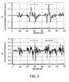
- FIG. 3 is charts showing transitions of the acceleration in the up-and-down directions, in which Fig. 3 (A) shows the transition of the acceleration in the up-and-down directions when using the configuration of this embodiment and Fig. 3(B) shows the transition of the acceleration in the up-and-down directions when using the configuration of the conventional art. Note that, in the charts, each zone from approximately 240 to 350 seconds and each zone from approximately 440 to 550 seconds are time ranges of traveling on the sloped ground.
- the speed/traveling-angle calculating module 30 acquires the gravity frequency component a x(G) s in the front-and-rear direction acceleration a x s in the sensor coordinate system acceleration [a x s , a y s , a z s ] from the frequency analyzing module 11. Further, the speed/traveling-angle calculating module 30 divides the gravity frequency component by the gravity acceleration g to calculate a correction traveling pitch angle ⁇ c.
- the speed/traveling-angle calculating module 30 performs weight averaging processing between the traveling pitch angle ⁇ , which can be obtained from Equations (18A) and (18B) described above, and the correction traveling pitch angle ⁇ c so as to calculate the traveling pitch angle to be outputted. By performing such processing, the summation error can be prevented from accumulating and the accuracy degradation due to a long-term operation processing can be suppressed.
- a timing for performing the weight averaging processing may be set to each timing of calculating the traveling pitch angle ⁇ , and, alternatively, may suitably be set to a longer predetermined timing interval.
- Fig. 4 is a block diagram showing a main configuration of the moving state detecting device 1' of this embodiment.
- the moving state detecting device 1' of this embodiment is the moving state detecting device 1 described in the first embodiment with a stop detecting module 40 added thereto.
- a stop detecting module 40 added thereto.
- the stop detecting module 40 acquires a stop detection acceleration [a x(AN) s , a y(AN) s , a z(AN) s ] comprised of a sum of the movement acceleration frequency component and the noise frequency component of the sensor coordinate system acceleration [a x s , a y s , a z s ].
- the stop detecting module 40 stores, in advance, thresholds ( ⁇ 0) for detecting a stop, for a front-and-rear direction component a x(AN) s and a left-and-right direction component a y(AN) s of the stop detection acceleration [a x(AN ) s , a y(AN) s , a z(AN) s ].
- thresholds ⁇ 0
- stop detecting module 40 detects that the front-and-rear direction component a x(AN) s and the left-and-right direction component a y(AN) s are both below the threshold for detecting the stop, it determines that the movable body is stopped and outputs stop detection data to the speed/traveling-angle calculating module 30.
- the stopping of the movable body can be distinguished through the simple processing.
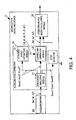
- Fig. 5 is a block diagram showing a main configuration of the moving state detecting device 100 of this embodiment.
- the moving state detecting device 100 of this embodiment calculates a position and a moving azimuth of the movable body based on various kinds of data from a GPS receiver 102 and angle speed data from a gyroscope 101, in addition to the speed and the traveling angle obtained with the configuration of the moving state detecting device 1 described in the first embodiment. Therefore, in the description below, description of parts that are same as the configuration of the moving state detecting device 1 described in the first embodiment are omitted and only different parts are described.
- the moving state detecting device 100 includes an azimuth calculating module 50 and a position calculating module 60 as well as the configuration of the moving state detecting device 1, and is connected with the gyroscope 101 and the GPS receiver 102.
- the gyroscope 101 is configured to be able to detect a turn in an azimuth direction at least, detects an angular velocity in the azimuth direction, and outputs it to the azimuth calculating module 60.
- the GPS receiver 102 receives GPS signals from GPS satellites, performs positioning based on the received GPS signals in the well-known method, and calculates GPS position data, GPS speed data, and GPS azimuth data.
- the GPS receiver 102 transmits the GPS position data to the position calculating module 60, transmits the GPS speed data to a speed/traveling-angle calculating module 30', and transmits the GPS azimuth data to the azimuth calculating module 50.
- the speed/traveling-angle calculating module 30' uses a differential value of the GPS speed data to calculate a traveling angle based on Equations (18A) and (18B) described above.
- the speed/traveling-angle calculating module 30' uses, for example, a weight average value of the differential value of the GPS speed data and the movable body coordinate system acceleration [a x b , a y b , a z b ], which is transmitted from the acceleration corrector 10, to calculate the traveling angle based on Equations (18A) and (18B) described above.
- the speed/traveling-angle calculating module 30' uses the GPS speed data, sets the latest outputted speed data to an initial value, and calculates a speed and the traveling angle based on Equations (18A) and (18B) described above.
- the azimuth calculating module 50 In the period of acquiring the GPS azimuth data, the azimuth calculating module 50 outputs the GPS azimuth data as it is. Alternatively, the azimuth calculating module 50 may calculate to output a weight average value of the GPS azimuth data and a value where the angular velocity data from the gyroscope 101 is integrated and added to the azimuth data precedingly outputted. Whereas, if the GPS azimuth data cannot be acquired, the azimuth calculating module 50, using the GPS azimuth data, sets the latest outputted azimuth data to an initial value, and, by integrating the angular velocity data and adding the angular velocity data to the initial value, calculates azimuth data.
- the position calculating module 60 In the period of acquiring the GPS azimuth data, the position calculating module 60 outputs the GPS position as it is. Alternatively, the position calculating module 60 may calculate to output a weight average value of the GPS position data and a value where speed vectors calculated from the speed data and the traveling angle data from the speed/traveling-angle calculating module 30 and the azimuth data from the azimuth calculating module 50 are integrated and added to the position data previously outputted.
- the position calculating module 60 uses the GPS position data, sets the latest outputted position data to an initial value, and, by integrating the speed vectors calculated from the speed data and the traveling angle data from the speed/traveling-angle calculating module 30 and the azimuth data from the azimuth calculating module 50 and adding the speed vector on the initial value, calculates position data.
- the position, speed, traveling angle, azimuth of the movable body can highly accurately be calculated.
- the various kinds of movement information of the movable body highly accurately detected as above is utilized in, for example, navigation processing by a navigation apparatus where the moving state detecting device 1 is mounted.
- This navigation apparatus at least includes a navigation processing module for executing route navigation processing, a display unit, a user interface, which the display unit can also have the same function. For example, according to an operation input from the user interface, the navigation module calculates an optimal route from a current position to a destination of the movable body, and displays the route on the display unit. Further, as described above, because the movement information of the movable body can be obtained highly accurately, the navigation apparatus can achieve accurate navigation processing.
- the wavelet transform is performed by the frequency analyzing module 11 .
- the wavelet transform is preferably utilized, other frequency conversion processing, such as Fourier transform processing may be performed, and further alternatively, by a plurality of filters having pass frequency bands different from each other, the sensor coordinate system acceleration [a x s , a y s , a z s ] may be divided into the frequency components, respectively.
- the acceleration corrector 10 is functionally divided into the frequency analyzing module 11, the attached angle estimating module 12, and the correcting operation module 13 is described; however, the functions of these modules may be achieved by a single arithmetic element and an executable program. Further, the functions of the acceleration corrector 10 and either one of the speed/traveling-angle calculating modules 30 and 30' may be achieved by a single arithmetic element and an executable program, and in addition thereto, the above functions with the inclusion of the stop detecting module 40 may be achieved by a single arithmetic element and an executable program.
- the example in which the three-dimensional attached angle [ ⁇ , ⁇ , ⁇ ] is estimation-calculated is described; however, at least one of the elements (the azimuth direction attached angle ⁇ , the pitch direction attached angle ⁇ , the roll direction attached angle ⁇ ) of the attached angle [ ⁇ , ⁇ , ⁇ ] may be estimation-calculated as required.
- the example in which the sensor coordinate system acceleration [a x s , a y s , a z s ] is divided into the four components of the bias frequency component, the gravity frequency component, the movement acceleration frequency component, and the noise frequency component and is used for the estimation calculation is described; however, in the sensor coordinate system acceleration [a x s , a y s , a z s ], at least the gravity frequency component and the movement acceleration frequency component may be derived to be used for the estimation calculation of the attached angle.
- a bandpass filter having frequency bands corresponding to the gravity frequency component and the movement acceleration frequency component as its pass bands may be used. Further, if using this bandpass filter, processing of, for example, varying the pass band corresponding to the moving state of the movable body, such as the traveling speed, may be performed.
Landscapes
- Engineering & Computer Science (AREA)
- Radar, Positioning & Navigation (AREA)
- Remote Sensing (AREA)
- Physics & Mathematics (AREA)
- General Physics & Mathematics (AREA)
- Automation & Control Theory (AREA)
- Manufacturing & Machinery (AREA)
- Navigation (AREA)
Applications Claiming Priority (2)
| Application Number | Priority Date | Filing Date | Title |
|---|---|---|---|
| JP2009121375A JP5736106B2 (ja) | 2009-05-19 | 2009-05-19 | 移動状態検出装置 |
| PCT/JP2010/056932 WO2010134411A1 (ja) | 2009-05-19 | 2010-04-19 | 移動状態検出装置 |
Publications (3)
| Publication Number | Publication Date |
|---|---|
| EP2434298A1 EP2434298A1 (en) | 2012-03-28 |
| EP2434298A4 EP2434298A4 (en) | 2012-11-21 |
| EP2434298B1 true EP2434298B1 (en) | 2014-04-02 |
Family
ID=43126097
Family Applications (1)
| Application Number | Title | Priority Date | Filing Date |
|---|---|---|---|
| EP10777646.0A Active EP2434298B1 (en) | 2009-05-19 | 2010-04-19 | Movement condition detection device |
Country Status (6)
| Country | Link |
|---|---|
| US (1) | US10012672B2 (ja) |
| EP (1) | EP2434298B1 (ja) |
| JP (1) | JP5736106B2 (ja) |
| KR (1) | KR101761933B1 (ja) |
| CN (1) | CN102422166B (ja) |
| WO (1) | WO2010134411A1 (ja) |
Families Citing this family (29)
| Publication number | Priority date | Publication date | Assignee | Title |
|---|---|---|---|---|
| US20100318257A1 (en) * | 2009-06-15 | 2010-12-16 | Deep Kalinadhabhotla | Method and system for automatically calibrating a three-axis accelerometer device |
| US20130238277A1 (en) * | 2010-11-18 | 2013-09-12 | Furuno Electric Co., Ltd. | Angular velocity detecting device, angular velocity detecting method, movement state detecting device and navigation device |
| US20120173195A1 (en) * | 2010-12-03 | 2012-07-05 | Qualcomm Incorporated | Inertial sensor aided heading and positioning for gnss vehicle navigation |
| JP6094026B2 (ja) * | 2011-03-02 | 2017-03-15 | セイコーエプソン株式会社 | 姿勢判定方法、位置算出方法及び姿勢判定装置 |
| JP5794624B2 (ja) * | 2011-07-26 | 2015-10-14 | 本田技研工業株式会社 | 自動二輪車のピッチ角推定装置及びピッチ角推定プログラム |
| WO2013049819A1 (en) * | 2011-09-30 | 2013-04-04 | Ims Solutions, Inc. | A method of correcting the orientation of a freely installed accelerometer in a vehicle |
| CN102506822B (zh) * | 2011-11-30 | 2013-10-23 | 北京天地玛珂电液控制系统有限公司 | 一种矿用倾角传感器 |
| BR112014025395B1 (pt) * | 2012-04-13 | 2022-07-26 | Wi-Tronix, Llc | Métodos para registrar, processar e transmitir dados a partir de um bem móvel |
| US9883173B2 (en) | 2013-12-25 | 2018-01-30 | 3Di Llc | Stereoscopic display |
| US9986228B2 (en) | 2016-03-24 | 2018-05-29 | 3Di Llc | Trackable glasses system that provides multiple views of a shared display |
| US10652525B2 (en) | 2013-10-31 | 2020-05-12 | 3Di Llc | Quad view display system |
| US11343487B2 (en) | 2013-10-31 | 2022-05-24 | David Woods | Trackable glasses system for perspective views of a display |
| JP6233727B2 (ja) * | 2013-12-05 | 2017-11-22 | ▲華▼▲為▼▲終▼端有限公司 | 車両加速度を判定するための方法および装置 |
| US11504029B1 (en) | 2014-10-26 | 2022-11-22 | David Martin | Mobile control using gait cadence |
| US20160166180A1 (en) * | 2014-12-11 | 2016-06-16 | David Martin | Enhanced Real Time Frailty Assessment for Mobile |
| KR102335738B1 (ko) * | 2014-12-10 | 2021-12-06 | 삼성전자주식회사 | 디바이스의 회전각 결정 방법 및 이를 위한 장치 |
| US10031236B2 (en) * | 2015-10-06 | 2018-07-24 | Topcon Positioning Systems, Inc. | Navigation receiver with an adaptive system for tracking carrier phases received from a constellation of navigation satellites |
| CN105807095B (zh) * | 2016-03-10 | 2019-01-11 | 同济大学 | 一种三轴加速度传感器安装误差修正方法 |
| DE102016220440A1 (de) * | 2016-10-19 | 2018-04-19 | Robert Bosch Gmbh | Navigationseinrichtung für Kraftfahrzeuge sowie Verfahren zur Navigation von Kraftfahrzeugen |
| CN107036630B (zh) * | 2017-04-27 | 2020-09-25 | 深圳市思拓通信系统有限公司 | 一种车辆驾驶预警装置安装角度的自动识别系统及方法 |
| CN109254172B (zh) * | 2017-07-12 | 2022-02-18 | 罗伯特·博世有限公司 | 车用加速度传感器的位置校准方法及装置、车辆控制设备 |
| JP2019020186A (ja) * | 2017-07-13 | 2019-02-07 | 株式会社グローバル・ニュークリア・フュエル・ジャパン | 加速度計、健全性検査装置及び方法 |
| JP7411915B2 (ja) * | 2018-10-19 | 2024-01-12 | パナソニックIpマネジメント株式会社 | 表示システム、表示装置、及び表示制御方法 |
| US11199410B2 (en) * | 2019-04-30 | 2021-12-14 | Stmicroelectronics, Inc. | Dead reckoning by determining misalignment angle between movement direction and sensor heading direction |
| US11747142B2 (en) * | 2019-04-30 | 2023-09-05 | Stmicroelectronics, Inc. | Inertial navigation system capable of dead reckoning in vehicles |
| CN110260841A (zh) * | 2019-06-10 | 2019-09-20 | 东南大学 | 倾角传感器 |
| JP2022072338A (ja) * | 2020-10-29 | 2022-05-17 | セイコーエプソン株式会社 | 慣性計測装置 |
| CN113566850B (zh) * | 2021-07-29 | 2024-03-08 | 深圳元戎启行科技有限公司 | 惯性测量单元的安装角度标定方法、装置和计算机设备 |
| KR102582056B1 (ko) * | 2023-05-26 | 2023-09-25 | 주식회사 원테이크 | 서라운드 뷰 제공 장치 및 이의 동작 방법 |
Family Cites Families (24)
| Publication number | Priority date | Publication date | Assignee | Title |
|---|---|---|---|---|
| US4213116A (en) * | 1979-01-22 | 1980-07-15 | Halperin Herbert H | Vehicle turn detection apparatus |
| JPH0943269A (ja) * | 1995-07-28 | 1997-02-14 | Omron Corp | 加速度トランスデューサ |
| JP3204121B2 (ja) * | 1996-09-30 | 2001-09-04 | 三菱自動車工業株式会社 | 車両用前後加速度推定装置 |
| JP3375268B2 (ja) * | 1997-05-27 | 2003-02-10 | 株式会社日立製作所 | ナビゲーション装置 |
| JPH11190743A (ja) * | 1997-12-26 | 1999-07-13 | Hokuriku Electric Ind Co Ltd | 移動体搭載用三軸加速度検出装置 |
| JP3662118B2 (ja) * | 1998-08-07 | 2005-06-22 | トヨタ自動車株式会社 | 車輌の加減速度演算方法 |
| DE19844911B4 (de) * | 1998-09-30 | 2006-01-05 | Robert Bosch Gmbh | Verfahren und Vorrichtung zur Überwachung eines in einem Fahrzeug eingesetzten Beschleunigungssensors |
| JP2001109738A (ja) | 1999-10-13 | 2001-04-20 | Toyota Motor Corp | ピーク時刻検出装置およびピーク時刻検出方法 |
| JP2004138553A (ja) * | 2002-10-18 | 2004-05-13 | Matsushita Electric Ind Co Ltd | 移動体位置検出装置、移動体位置検出方法、プログラムおよび記録媒体 |
| JP4191499B2 (ja) * | 2003-02-03 | 2008-12-03 | パイオニア株式会社 | 車載装置 |
| JP3808480B2 (ja) * | 2004-06-25 | 2006-08-09 | 株式会社高見沢サイバネティックス | 感震器及び地震計システム |
| EP1788397A4 (en) * | 2004-09-07 | 2011-11-02 | Vodafone Plc | WATER POUCH FOR ULTRASONIC PROBE USED IN ULTRASONIC DIAGNOSTIC DEVICE |
| EP1708362B1 (en) | 2005-03-31 | 2008-12-31 | STMicroelectronics S.r.l. | Displacement detection device of a portable apparatus using a digital high-pass filter |
| DE102005030295B4 (de) | 2005-06-24 | 2008-11-20 | Siemens Ag | Fahrzeuggeschwindigkeitssensor |
| JP2007107951A (ja) * | 2005-10-12 | 2007-04-26 | Matsushita Electric Ind Co Ltd | 取付け角度算出装置 |
| JP4655901B2 (ja) * | 2005-11-21 | 2011-03-23 | パナソニック株式会社 | 移動体の水平走行判定装置及び方法 |
| JP4955285B2 (ja) * | 2006-03-03 | 2012-06-20 | マイクロストーン株式会社 | 傾斜角測定センサ |
| US7292925B1 (en) | 2006-03-08 | 2007-11-06 | Yamaha Hatsudoki Kabushiki Kaisha | Acceleration estimation device and vehicle |
| JP2006227018A (ja) * | 2006-03-24 | 2006-08-31 | Denso Corp | 加速度を利用した処理装置 |
| JP4816340B2 (ja) * | 2006-08-31 | 2011-11-16 | ソニー株式会社 | ナビゲーション装置、位置検出方法及び位置検出プログラム |
| JP4779891B2 (ja) * | 2006-09-04 | 2011-09-28 | ソニー株式会社 | ナビゲーション装置、停止検出方法及び停止検出プログラム |
| US7665361B2 (en) | 2007-01-25 | 2010-02-23 | Freescale Semiconductor, Inc. | Method and apparatus for closed loop offset cancellation |
| US7979207B2 (en) * | 2007-03-19 | 2011-07-12 | Sirf Technology, Inc. | Systems and methods for detecting a vehicle static condition |
| JP4964047B2 (ja) * | 2007-07-12 | 2012-06-27 | アルパイン株式会社 | 位置検出装置及び位置検出方法 |
-
2009
- 2009-05-19 JP JP2009121375A patent/JP5736106B2/ja active Active
-
2010
- 2010-04-19 WO PCT/JP2010/056932 patent/WO2010134411A1/ja active Application Filing
- 2010-04-19 EP EP10777646.0A patent/EP2434298B1/en active Active
- 2010-04-19 US US13/265,762 patent/US10012672B2/en active Active
- 2010-04-19 KR KR1020117030370A patent/KR101761933B1/ko active IP Right Grant
- 2010-04-19 CN CN201080020698.3A patent/CN102422166B/zh active Active
Also Published As
| Publication number | Publication date |
|---|---|
| CN102422166A (zh) | 2012-04-18 |
| JP5736106B2 (ja) | 2015-06-17 |
| KR20120050413A (ko) | 2012-05-18 |
| KR101761933B1 (ko) | 2017-07-26 |
| EP2434298A1 (en) | 2012-03-28 |
| US20120041702A1 (en) | 2012-02-16 |
| US10012672B2 (en) | 2018-07-03 |
| JP2010271086A (ja) | 2010-12-02 |
| EP2434298A4 (en) | 2012-11-21 |
| CN102422166B (zh) | 2015-06-03 |
| WO2010134411A1 (ja) | 2010-11-25 |
Similar Documents
| Publication | Publication Date | Title |
|---|---|---|
| EP2434298B1 (en) | Movement condition detection device | |
| US20130238277A1 (en) | Angular velocity detecting device, angular velocity detecting method, movement state detecting device and navigation device | |
| US11480587B2 (en) | Systems and methods for low latency 3-axis accelerometer calibration | |
| US6826478B2 (en) | Inertial navigation system for mobile objects with constraints | |
| EP2959376B1 (en) | Systems and methods for 3-axis accelerometer calibration with vertical sample buffers | |
| KR101417456B1 (ko) | 차량 요레이트센서의 바이어스 획득방법 | |
| EP2854112B1 (en) | Low-impact crash detection system | |
| US20090005985A1 (en) | GPS-based in-vehicle sensor calibration algorithm | |
| US20130073142A1 (en) | Systems and Methods for 3-Axis Accelerometer Calibration | |
| US20100292915A1 (en) | Car navigation system | |
| CN102096087A (zh) | Gps增强的车辆速度估计 | |
| ES2763450T3 (es) | Dispositivo de estimación del ángulo de balanceo de un vehículo | |
| JP2013145168A (ja) | 車載用ジャイロの角速度誤差補正装置 | |
| EP2596380B1 (en) | A system and method of determining an unambiguous heading direction of a vehicle | |
| JP2007064880A (ja) | 速度表示装置 | |
| JP6215915B2 (ja) | 速度算出装置、及び速度算出方法 | |
| US11085773B2 (en) | Angular velocity sensor correction device and method for correcting output signal from angular velocity sensor, and direction estimation device and method for estimating direction by correcting output signal from angular velocity sensor | |
| EP3967976B1 (en) | A method for motion estimation in a vehicle, corresponding device and computer program product | |
| US9791277B2 (en) | Apparatus and method for measuring velocity of moving object in a navigation system | |
| JP3169213B2 (ja) | 移動速度検出方法及び装置、車両のすべり角検出装置 | |
| KR20140044966A (ko) | 차량 자세 보정 장치 |
Legal Events
| Date | Code | Title | Description |
|---|---|---|---|
| PUAI | Public reference made under article 153(3) epc to a published international application that has entered the european phase |
Free format text: ORIGINAL CODE: 0009012 |
|
| 17P | Request for examination filed |
Effective date: 20110916 |
|
| AK | Designated contracting states |
Kind code of ref document: A1 Designated state(s): AT BE BG CH CY CZ DE DK EE ES FI FR GB GR HR HU IE IS IT LI LT LU LV MC MK MT NL NO PL PT RO SE SI SK SM TR |
|
| DAX | Request for extension of the european patent (deleted) | ||
| A4 | Supplementary search report drawn up and despatched |
Effective date: 20121019 |
|
| RIC1 | Information provided on ipc code assigned before grant |
Ipc: G01C 21/00 20060101ALI20121015BHEP Ipc: G01P 21/00 20060101AFI20121015BHEP |
|
| GRAP | Despatch of communication of intention to grant a patent |
Free format text: ORIGINAL CODE: EPIDOSNIGR1 |
|
| INTG | Intention to grant announced |
Effective date: 20130906 |
|
| RAP1 | Party data changed (applicant data changed or rights of an application transferred) |
Owner name: FURUNO ELECTRIC CO., LTD. |
|
| GRAS | Grant fee paid |
Free format text: ORIGINAL CODE: EPIDOSNIGR3 |
|
| GRAA | (expected) grant |
Free format text: ORIGINAL CODE: 0009210 |
|
| AK | Designated contracting states |
Kind code of ref document: B1 Designated state(s): AT BE BG CH CY CZ DE DK EE ES FI FR GB GR HR HU IE IS IT LI LT LU LV MC MK MT NL NO PL PT RO SE SI SK SM TR |
|
| REG | Reference to a national code |
Ref country code: GB Ref legal event code: FG4D |
|
| REG | Reference to a national code |
Ref country code: AT Ref legal event code: REF Ref document number: 660431 Country of ref document: AT Kind code of ref document: T Effective date: 20140415 Ref country code: CH Ref legal event code: EP |
|
| REG | Reference to a national code |
Ref country code: IE Ref legal event code: FG4D |
|
| REG | Reference to a national code |
Ref country code: DE Ref legal event code: R096 Ref document number: 602010014863 Country of ref document: DE Effective date: 20140515 |
|
| REG | Reference to a national code |
Ref country code: AT Ref legal event code: MK05 Ref document number: 660431 Country of ref document: AT Kind code of ref document: T Effective date: 20140402 |
|
| REG | Reference to a national code |
Ref country code: NL Ref legal event code: VDEP Effective date: 20140402 |
|
| REG | Reference to a national code |
Ref country code: LT Ref legal event code: MG4D |
|
| PG25 | Lapsed in a contracting state [announced via postgrant information from national office to epo] |
Ref country code: IS Free format text: LAPSE BECAUSE OF FAILURE TO SUBMIT A TRANSLATION OF THE DESCRIPTION OR TO PAY THE FEE WITHIN THE PRESCRIBED TIME-LIMIT Effective date: 20140802 Ref country code: NO Free format text: LAPSE BECAUSE OF FAILURE TO SUBMIT A TRANSLATION OF THE DESCRIPTION OR TO PAY THE FEE WITHIN THE PRESCRIBED TIME-LIMIT Effective date: 20140702 Ref country code: BG Free format text: LAPSE BECAUSE OF FAILURE TO SUBMIT A TRANSLATION OF THE DESCRIPTION OR TO PAY THE FEE WITHIN THE PRESCRIBED TIME-LIMIT Effective date: 20140702 Ref country code: LT Free format text: LAPSE BECAUSE OF FAILURE TO SUBMIT A TRANSLATION OF THE DESCRIPTION OR TO PAY THE FEE WITHIN THE PRESCRIBED TIME-LIMIT Effective date: 20140402 Ref country code: GR Free format text: LAPSE BECAUSE OF FAILURE TO SUBMIT A TRANSLATION OF THE DESCRIPTION OR TO PAY THE FEE WITHIN THE PRESCRIBED TIME-LIMIT Effective date: 20140703 Ref country code: FI Free format text: LAPSE BECAUSE OF FAILURE TO SUBMIT A TRANSLATION OF THE DESCRIPTION OR TO PAY THE FEE WITHIN THE PRESCRIBED TIME-LIMIT Effective date: 20140402 Ref country code: NL Free format text: LAPSE BECAUSE OF FAILURE TO SUBMIT A TRANSLATION OF THE DESCRIPTION OR TO PAY THE FEE WITHIN THE PRESCRIBED TIME-LIMIT Effective date: 20140402 Ref country code: CY Free format text: LAPSE BECAUSE OF FAILURE TO SUBMIT A TRANSLATION OF THE DESCRIPTION OR TO PAY THE FEE WITHIN THE PRESCRIBED TIME-LIMIT Effective date: 20140402 Ref country code: CZ Free format text: LAPSE BECAUSE OF FAILURE TO SUBMIT A TRANSLATION OF THE DESCRIPTION OR TO PAY THE FEE WITHIN THE PRESCRIBED TIME-LIMIT Effective date: 20140402 |
|
| PG25 | Lapsed in a contracting state [announced via postgrant information from national office to epo] |
Ref country code: HR Free format text: LAPSE BECAUSE OF FAILURE TO SUBMIT A TRANSLATION OF THE DESCRIPTION OR TO PAY THE FEE WITHIN THE PRESCRIBED TIME-LIMIT Effective date: 20140402 Ref country code: LV Free format text: LAPSE BECAUSE OF FAILURE TO SUBMIT A TRANSLATION OF THE DESCRIPTION OR TO PAY THE FEE WITHIN THE PRESCRIBED TIME-LIMIT Effective date: 20140402 Ref country code: AT Free format text: LAPSE BECAUSE OF FAILURE TO SUBMIT A TRANSLATION OF THE DESCRIPTION OR TO PAY THE FEE WITHIN THE PRESCRIBED TIME-LIMIT Effective date: 20140402 Ref country code: PL Free format text: LAPSE BECAUSE OF FAILURE TO SUBMIT A TRANSLATION OF THE DESCRIPTION OR TO PAY THE FEE WITHIN THE PRESCRIBED TIME-LIMIT Effective date: 20140402 Ref country code: ES Free format text: LAPSE BECAUSE OF FAILURE TO SUBMIT A TRANSLATION OF THE DESCRIPTION OR TO PAY THE FEE WITHIN THE PRESCRIBED TIME-LIMIT Effective date: 20140402 Ref country code: SE Free format text: LAPSE BECAUSE OF FAILURE TO SUBMIT A TRANSLATION OF THE DESCRIPTION OR TO PAY THE FEE WITHIN THE PRESCRIBED TIME-LIMIT Effective date: 20140402 |
|
| REG | Reference to a national code |
Ref country code: CH Ref legal event code: PL |
|
| PG25 | Lapsed in a contracting state [announced via postgrant information from national office to epo] |
Ref country code: PT Free format text: LAPSE BECAUSE OF FAILURE TO SUBMIT A TRANSLATION OF THE DESCRIPTION OR TO PAY THE FEE WITHIN THE PRESCRIBED TIME-LIMIT Effective date: 20140804 |
|
| REG | Reference to a national code |
Ref country code: DE Ref legal event code: R097 Ref document number: 602010014863 Country of ref document: DE |
|
| REG | Reference to a national code |
Ref country code: IE Ref legal event code: MM4A |
|
| PG25 | Lapsed in a contracting state [announced via postgrant information from national office to epo] |
Ref country code: CH Free format text: LAPSE BECAUSE OF NON-PAYMENT OF DUE FEES Effective date: 20140430 Ref country code: SK Free format text: LAPSE BECAUSE OF FAILURE TO SUBMIT A TRANSLATION OF THE DESCRIPTION OR TO PAY THE FEE WITHIN THE PRESCRIBED TIME-LIMIT Effective date: 20140402 Ref country code: BE Free format text: LAPSE BECAUSE OF FAILURE TO SUBMIT A TRANSLATION OF THE DESCRIPTION OR TO PAY THE FEE WITHIN THE PRESCRIBED TIME-LIMIT Effective date: 20140402 Ref country code: RO Free format text: LAPSE BECAUSE OF FAILURE TO SUBMIT A TRANSLATION OF THE DESCRIPTION OR TO PAY THE FEE WITHIN THE PRESCRIBED TIME-LIMIT Effective date: 20140402 Ref country code: LI Free format text: LAPSE BECAUSE OF NON-PAYMENT OF DUE FEES Effective date: 20140430 Ref country code: EE Free format text: LAPSE BECAUSE OF FAILURE TO SUBMIT A TRANSLATION OF THE DESCRIPTION OR TO PAY THE FEE WITHIN THE PRESCRIBED TIME-LIMIT Effective date: 20140402 Ref country code: MC Free format text: LAPSE BECAUSE OF FAILURE TO SUBMIT A TRANSLATION OF THE DESCRIPTION OR TO PAY THE FEE WITHIN THE PRESCRIBED TIME-LIMIT Effective date: 20140402 Ref country code: DK Free format text: LAPSE BECAUSE OF FAILURE TO SUBMIT A TRANSLATION OF THE DESCRIPTION OR TO PAY THE FEE WITHIN THE PRESCRIBED TIME-LIMIT Effective date: 20140402 |
|
| PLBE | No opposition filed within time limit |
Free format text: ORIGINAL CODE: 0009261 |
|
| STAA | Information on the status of an ep patent application or granted ep patent |
Free format text: STATUS: NO OPPOSITION FILED WITHIN TIME LIMIT |
|
| 26N | No opposition filed |
Effective date: 20150106 |
|
| PG25 | Lapsed in a contracting state [announced via postgrant information from national office to epo] |
Ref country code: IT Free format text: LAPSE BECAUSE OF FAILURE TO SUBMIT A TRANSLATION OF THE DESCRIPTION OR TO PAY THE FEE WITHIN THE PRESCRIBED TIME-LIMIT Effective date: 20140402 |
|
| REG | Reference to a national code |
Ref country code: DE Ref legal event code: R097 Ref document number: 602010014863 Country of ref document: DE Effective date: 20150106 |
|
| PG25 | Lapsed in a contracting state [announced via postgrant information from national office to epo] |
Ref country code: IE Free format text: LAPSE BECAUSE OF NON-PAYMENT OF DUE FEES Effective date: 20140419 |
|
| PG25 | Lapsed in a contracting state [announced via postgrant information from national office to epo] |
Ref country code: SI Free format text: LAPSE BECAUSE OF FAILURE TO SUBMIT A TRANSLATION OF THE DESCRIPTION OR TO PAY THE FEE WITHIN THE PRESCRIBED TIME-LIMIT Effective date: 20140402 |
|
| REG | Reference to a national code |
Ref country code: FR Ref legal event code: PLFP Year of fee payment: 7 |
|
| PG25 | Lapsed in a contracting state [announced via postgrant information from national office to epo] |
Ref country code: MT Free format text: LAPSE BECAUSE OF FAILURE TO SUBMIT A TRANSLATION OF THE DESCRIPTION OR TO PAY THE FEE WITHIN THE PRESCRIBED TIME-LIMIT Effective date: 20140402 |
|
| PG25 | Lapsed in a contracting state [announced via postgrant information from national office to epo] |
Ref country code: SM Free format text: LAPSE BECAUSE OF FAILURE TO SUBMIT A TRANSLATION OF THE DESCRIPTION OR TO PAY THE FEE WITHIN THE PRESCRIBED TIME-LIMIT Effective date: 20140402 |
|
| PG25 | Lapsed in a contracting state [announced via postgrant information from national office to epo] |
Ref country code: LU Free format text: LAPSE BECAUSE OF NON-PAYMENT OF DUE FEES Effective date: 20140419 Ref country code: HU Free format text: LAPSE BECAUSE OF FAILURE TO SUBMIT A TRANSLATION OF THE DESCRIPTION OR TO PAY THE FEE WITHIN THE PRESCRIBED TIME-LIMIT; INVALID AB INITIO Effective date: 20100419 Ref country code: TR Free format text: LAPSE BECAUSE OF FAILURE TO SUBMIT A TRANSLATION OF THE DESCRIPTION OR TO PAY THE FEE WITHIN THE PRESCRIBED TIME-LIMIT Effective date: 20140402 |
|
| REG | Reference to a national code |
Ref country code: FR Ref legal event code: PLFP Year of fee payment: 8 |
|
| REG | Reference to a national code |
Ref country code: FR Ref legal event code: PLFP Year of fee payment: 9 |
|
| PG25 | Lapsed in a contracting state [announced via postgrant information from national office to epo] |
Ref country code: MK Free format text: LAPSE BECAUSE OF FAILURE TO SUBMIT A TRANSLATION OF THE DESCRIPTION OR TO PAY THE FEE WITHIN THE PRESCRIBED TIME-LIMIT Effective date: 20140402 |
|
| PGFP | Annual fee paid to national office [announced via postgrant information from national office to epo] |
Ref country code: FR Payment date: 20230309 Year of fee payment: 14 |
|
| P01 | Opt-out of the competence of the unified patent court (upc) registered |
Effective date: 20230523 |
|
| PGFP | Annual fee paid to national office [announced via postgrant information from national office to epo] |
Ref country code: DE Payment date: 20230228 Year of fee payment: 14 |
|
| PGFP | Annual fee paid to national office [announced via postgrant information from national office to epo] |
Ref country code: GB Payment date: 20240229 Year of fee payment: 15 |