EP2433853A2 - Landwirtschaftliche Maschine und Raupenlaufwerk dafür - Google Patents
Landwirtschaftliche Maschine und Raupenlaufwerk dafür Download PDFInfo
- Publication number
- EP2433853A2 EP2433853A2 EP11172046A EP11172046A EP2433853A2 EP 2433853 A2 EP2433853 A2 EP 2433853A2 EP 11172046 A EP11172046 A EP 11172046A EP 11172046 A EP11172046 A EP 11172046A EP 2433853 A2 EP2433853 A2 EP 2433853A2
- Authority
- EP
- European Patent Office
- Prior art keywords
- crawler belt
- wheels
- caterpillar drive
- caterpillar
- impeller
- Prior art date
- Legal status (The legal status is an assumption and is not a legal conclusion. Google has not performed a legal analysis and makes no representation as to the accuracy of the status listed.)
- Granted
Links
Images


Classifications
-
- B—PERFORMING OPERATIONS; TRANSPORTING
- B62—LAND VEHICLES FOR TRAVELLING OTHERWISE THAN ON RAILS
- B62D—MOTOR VEHICLES; TRAILERS
- B62D55/00—Endless track vehicles
- B62D55/08—Endless track units; Parts thereof
- B62D55/14—Arrangement, location, or adaptation of rollers
-
- B—PERFORMING OPERATIONS; TRANSPORTING
- B62—LAND VEHICLES FOR TRAVELLING OTHERWISE THAN ON RAILS
- B62D—MOTOR VEHICLES; TRAILERS
- B62D55/00—Endless track vehicles
- B62D55/08—Endless track units; Parts thereof
- B62D55/18—Tracks
- B62D55/24—Tracks of continuously flexible type, e.g. rubber belts
- B62D55/244—Moulded in one piece, with either smooth surfaces or surfaces having projections, e.g. incorporating reinforcing elements
Definitions
- the present invention relates generally to a caterpillar drive, and more particularly to an agricultural machine equipped with a caterpillar drive.
- An agricultural machine with a caterpillar drive according to the preamble of claim 1 is among others EP 1 840 018 B1 known.
- Crawler tracks are of interest for use on agricultural machines, as they allow the weight of the machine to be distributed over a large area, thus counteracting compaction of the ground traveled by the machine.
- a considerable disadvantage of conventional caterpillar drives is their high susceptibility to wear. The associated high operating costs make their use in many cases uneconomic in the short term, where it would be long term to protect the soil would be quite appropriate.
- Fig. 1 is a schematic section through a conventional caterpillar drive, the reasons for the high wear is illustrated.
- a typical conventional caterpillar drive comprises at least two wheels 1 of substantially cylindrical shape, which are looped by a tightly tensioned crawler belt 2.
- the crawler belt 2 carries on its inside a plurality of guide blocks 3, which engage in circumferential grooves 4 of the wheels 1.
- the axles 5 of the wheels 1 should be aligned exactly parallel to each other. In practice, this never succeeds perfectly, as in Fig. 1 greatly exaggerated.
- the consequences of imperfect parallelism of the axes 5 is that the tension of the crawler belt 2 on different sides of its guide blocks 3 is different.
- Fig. 1 In the presentation of the Fig. 1 is the misalignment of the right wheel 1 so strong that one half of the crawler belt 2 (the lower in the representation of Fig. 1 ) is stretched elastically, while the opposite half wraps around the right wheel 1 play. Tensile stresses therefore occur essentially only in the lower half of the crawler belt 2, with the result that the crawler belt 2 tends to dodge downwards. The thus further increasing tension of the crawler belt 2 leads to increased friction between its inner surfaces and the circumferential surfaces of the wheels wrapped around it 1. In addition, they can have an inelastic stretch of the crawler belt 2 result, resulting in that the tension of the crawler belt second must be constantly readjusted and the crawler belt is unusable when the adjustment of the adjustment is exhausted. Although an all too strong lateral deviation of the crawler belt 2 and the related strain are avoided by the guide blocks 3 abut an edge of the grooves 4, but then the guide blocks 3 are exposed to a strong unilateral fretting on the grooves 4 limiting edges of the wheels 1.
- a caterpillar drive in which the orientation of the axis of a wheel is adjustable.
- an adjustment mechanism has to be extremely rigid and can therefore only be realized with great effort and expense.
- the adjustment for the operator of a machine equipped with such a caterpillar drive regularly causes effort and costs that affect the economic efficiency of the machine.
- the object of the invention is therefore to provide a caterpillar drive, which inherently, without the need for a complex adjustment, has a low tendency to wear.
- the object is achieved by carrying out at least one crowned of the active surfaces of the wheels in a caterpillar drive with at least two wheels and an endless crawler belt, which wraps the active surfaces of the wheels.
- the crowned shape of the treads causes the stress acting in the crawler belt to decrease from the center of the crawler belt towards the edges, this stress distribution also being due to parallelism errors the wheels are not fundamentally affected. It can thus not come to extremely high voltages at the edges of the crawler belt, which deflect the crawler belt in the lateral direction.
- the spherical surface of the at least one impeller is circular arc-shaped in cross-section along an axis of this impeller.
- the bottom friction on the caterpillar track of a caterpillar drive acts on a torque that tends to deflect the crawler at the front and the rear looped impeller in opposite directions. If the crowning of the surface is too strong, such a rotation of the crawler belt will result in a decrease in its tension, and a force will be lacking which will drive the crawler belt back to its normal position.
- the diameter of the circular arc of the axial cross section of the impeller preferably corresponds at least to the length of the caterpillar drive.
- the spherical impeller may comprise at least two truncated cones, the large base surfaces facing each other.
- a high concentration of stress in the area of the contacting large base surfaces can in turn lead to increased fretting wear of the crawler belt in this area.
- the spherical impeller between the two truncated cones has a cylindrical portion on which distributes the stress.
- the wheels and crawler belt may include intermeshing grooves and springs.
- Subject of the invention is also an agricultural machine having at least one caterpillar drive of the type described above.
- the caterpillar drive can be used both in a crawler chassis and in a crawler chassis.
- FIG. 2 shows a combine harvester 10 as an example of an agricultural machine to which the invention is applicable.
- a chassis of the combine harvester 10 is designed as a semi-crawler chassis, with two caterpillars 11, which carry the weight of the front part of the body of the combine 10 and a cutting attachment 12, and a rear axle with rubber-tired wheels 13, the Compared to the front part relatively light rear of the combine 10 is supported.
- the two caterpillar drives 11 each comprise a front and a rear wheel 14 and 15, of which at least one is driven and which are respectively looped on each half of its circumference by an endless crawler belt 16.
- the wheels 14, 15 arranged near the ground support wheels 17 hold a lower strand of the crawler belt 16 in continuous ground contact and ensure a uniform weight distribution over the entire contact surface between the ground and crawler belt 16th
- the caterpillars 11 can also be used in a crawler chassis, or that these caterpillars can also be provided on other field-driving agricultural machines, such as a tractor, a forage harvester, etc.
- Fig. 3 shows in one too Fig. 2
- a central drive wheel 18 is greater than before and behind arranged, to less than half their circumference of the crawler belt 16 looped wheels 14, 15.
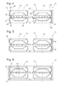
- Fig. 4 shows a section through a caterpillar drive 11 along a horizontal plane passing through axes of rotation 20 of the two wheels 14, 15 level. Between the wheels 14, 15 arranged more Wheels such as the support wheels 17 or the drive wheel 18 are not shown in the figure, since they have no meaning for the effect of the invention.
- the crawler belt 16 has an outer and an inner side 21 and 22, respectively.
- the outer side 21 is in Fig. 4 for the sake of simplicity, it will be understood that the outer side 21 may be provided with any suitable profile for improving the transmission of power between the crawler belt 16 and the ground being traveled.
- the inner side 22 comprises two cross-sectionally flat strips 23 which are separated from each other by a series of inwardly projecting guide blocks 24.
- the wheels 14, 15 looped by the crawler belt 16 are identical in construction and each consist of two identical, mirror-inverted elements 25, each having a substantially in the radial direction with respect to the axes 20 extending wheel disc 26 and an extended in the axial direction peripheral surface 27 have.
- the wheel discs 26 are mounted on a non-illustrated wheel hub at such a distance from each other that between the peripheral surfaces 27 of the two elements 25 of each impeller 14, 15, a groove 28 remains free, in which the guide blocks 24 engage with play.
- the peripheral surfaces 27 are curved in an arc-shaped manner in axial section, wherein their radius of curvature is greater than that of a in Fig. 4 designated 29 imaginary circle whose diameter corresponds to the length of the caterpillar drive 11.
- the guide blocks 24 engage centrally in the grooves 28 without touching the wheel discs 26 on both sides, and the peripheral surfaces 27 touch the inside 22 of the crawler belt 16 only in the immediate vicinity to the groove 28.
- Fig. 1 As from the consideration of Fig. 1 becomes clear, in a conventional crawler drive with cylindrical wheels 1, the elongation of the crawler belt 16 at non-parallelism of the axes of rotation 20 at one edge of the crawler belt 16 at the strongest. In contrast, moves in the crawler drive 11 of the Fig. 4 the area of the strongest tension in the case of an alignment error only slightly to the side, and also the tension of the crawler belt 16 increases only slightly. Therefore, the inventive drive 11 can tolerate relatively large alignment errors of the axes 20, without resulting in excessive friction of the guide blocks 24 on the flanks of the groove 28. Therefore, the crawler drive 11 may be equipped with fixed, non-adjustable pivot axes 20. This makes the drive 11 economically priced for the user, as well as economical to operate, due to the continuing need to adjust the wheels.
- Fig. 5 shows a second embodiment of the crawler drive 11 in one Fig. 4 analogue cut.
- the shape of the wheels 14, 15 is the same as in Fig. 4 and also the outer shape of the crawler belt 16 is the same.
- the difference lies in the internal structure of the crawler belt 16, which in the embodiment of Fig. 5 with two groups of inserted steel cables 30 on both sides of the guide blocks 24 is provided.
- the steel cords 30 impart high tensile strength to the crawler belt 16 so that, while an axle alignment error or twisting of the crawler belt 16 causes only slight elongation during cornering, this stretch within the crawler 11 causes forces large enough to retard the crawler belt 16 a deflection reliable in his in Fig. 5 attributed center position.
- the crawler belt 16 has the same shape as in the embodiment of FIGS. 6 and 7 , but in the wheels 14, 15 are in cross section circular arc-shaped peripheral surfaces 27 of FIGS. 4 to 7 replaced by frustoconical, in cross section to the around them wrapped around strip 23 of the crawler belt 16 parallel peripheral surfaces 31.
- both strips 23 are uniformly stretched by the contact with the peripheral surfaces 31 over its entire width, there are therefore no tracks on the crawler belt 16, which are exposed to a particularly high, possibly leading to fatigue and premature wear stress.
- the tension is concentrated on one of the two strips 23, so that the crawler belt 16 strives back to the center position.
- each deflection of the crawler belt 16 from its center position leads to an unequal distribution of the stresses and consequently to a drift movement of the crawler belt 16. If this drift movement exceeds the middle position, an uneven distribution of the stresses occurs again, and a drift movement in the opposite direction begins.
- a constant oscillation of the crawler belt 16 about its center position can in turn lead to friction losses and increased wear.
- the wheels 14, 15 on both sides of the groove 28 each cylindrical peripheral surface portions 32 and outwardly thereafter, conical peripheral surface portions 33.
- the inside 22 of the crawler belt 16 on both sides of the guide blocks 24 lying on a same line strips 34 and, outwardly adjacent to these, parallel to the conical portions 33 of the wheels inclined strips 35. Since the strips 34 are wider than the cylindrical peripheral surface portions 32, the crawler belt 16 on the wheels 14, 15 can move to some extent in the lateral direction, without any restoring forces occur. A swinging back and forth of the crawler belt 16 is avoided.
Landscapes
- Engineering & Computer Science (AREA)
- Chemical & Material Sciences (AREA)
- Combustion & Propulsion (AREA)
- Transportation (AREA)
- Mechanical Engineering (AREA)
- Harvester Elements (AREA)
- Transplanting Machines (AREA)
Abstract
Description
- Die vorliegende Erfindung betrifft allgemein ein Raupenlaufwerk und insbesondere eine landwirtschaftliche Maschine, die mit einem Raupenlaufwerk ausgestattet ist.
- Eine landwirtschaftliche Maschine mit einem Raupenlaufwerk nach dem Oberbegriff des Anspruchs 1 ist unter anderem aus
EP 1 840 018 B1 bekannt. - Raupenlaufwerke sind für den Einsatz an landwirtschaftlichen Maschinen interessant, da sie es erlauben, das Gewicht der Maschine auf eine große Fläche zu verteilen und so einer Verdichtung des von der Maschine befahrenen Bodens entgegenzuwirken. Ein erheblicher Nachteil herkömmlicher Raupenlaufwerke ist ihre hohe Verschleißanfälligkeit. Die damit verbundenen hohen Betriebskosten machen ihren Einsatz in vielen Fällen kurzfristig unwirtschaftlich, wo er langfristig zur Schonung des Bodens durchaus angezeigt wäre.
-
Fig. 1 ist ein schematischer Schnitt durch ein herkömmliches Raupenlaufwerk, der die Gründe für den hohen Verschleiß veranschaulicht. Ein typisches herkömmliches Raupenlaufwerk umfasst wenigstens zwei Räder 1 von im Wesentlichen zylindrischer Form, die von einem straff gespannten Raupenband 2 umschlungen sind. Um sicherzustellen, dass das Raupenband 2 nicht in seitlicher bzw. axialer Richtung von den Rädern 1 abgleiten kann, trägt es an seiner Innenseite eine Vielzahl von Führungsblöcken 3, die in umlaufende Nuten 4 der Räder 1 eingreifen. Im Idealfall sollten die Achsen 5 der Räder 1 exakt parallel zueinander ausgerichtet sein. In der Praxis gelingt dies nie perfekt, wie inFig. 1 stark übertrieben dargestellt. Die Folgen einer nicht perfekten Parallelität der Achsen 5 ist, dass die Spannung des Raupenbandes 2 auf verschiedenen Seiten seiner Führungsblöcke 3 unterschiedlich ist. In der Darstellung derFig. 1 ist die Fehlstellung des rechten Rades 1 so stark, dass eine Hälfte des Raupenbandes 2 (die untere in der Darstellung derFig. 1 ) elastisch gedehnt ist, während die entgegengesetzte Hälfte das rechte Rad 1 spielhaltig umschlingt. Zugspannungen treten daher im Wesentlichen nur in der unteren Hälfte des Raupenbandes 2 auf, mit der Folge, dass das Raupenband 2 dazu neigt, nach unten auszuweichen. Die dadurch noch weiter zunehmende Spannung des Raupenbandes 2 führt zu erhöhter Reibung zwischen seinen Innenflächen und den von ihm umschlungen Umfangsflächen der Räder 1. Darüber hinaus kann sie eine inelastische Streckung des Raupenbandes 2 zur Folge haben, was dazu führt, dass die Spannung des Raupenbandes 2 ständig nachjustiert werden muss und das Raupenband unbrauchbar wird, wenn der Verstellbereich der Justiermittel ausgeschöpft ist. Zwar kann eine allzu starke Seitwärtsabweichung des Raupenbandes 2 und die damit zusammenhängende Dehnung vermieden werden, indem die Führungsblöcke 3 an einem Rand der Nuten 4 anstoßen, doch sind dann die Führungsblöcke 3 einem starken einseitigen Reibverschleiß an den die Nuten 4 begrenzenden Flanken der Räder 1 ausgesetzt. - Aus
DE 101 14 400 A1 ist ein Raupenlaufwerk bekannt, bei dem die Orientierung der Achse eines Rades justierbar ist. Ein solcher Justiermechanismus muss, um wirksam zu sein, extrem starr sein, und ist daher nur mit hohem Aufwand und Kosten realisierbar. Darüber hinaus verursacht die Justierung für den Betreiber einer mit einem solchen Raupenlaufwerk ausgestatteten Maschine regelmäßig Aufwand und Kosten, die die Wirtschaftlichkeit der Maschine beeinträchtigen. - Aufgabe der Erfindung ist daher, ein Raupenlaufwerk zu schaffen, das inhärent, ohne die Notwendigkeit einer aufwändigen Justage, eine geringe Verschleißneigung aufweist.
- Die Aufgabe wird gelöst, indem bei einem Raupenlaufwerk mit wenigstens zwei Laufrädern und einem endlosen Raupenband, das Wirkoberflächen der Laufräder umschlingt, von den Wirkoberflächen der Laufräder wenigstens eine ballig ausgeführt ist.
- Die ballige Form der Laufflächen führt dazu, dass die in dem Raupenband wirkende Spannung von der Mitte des Raupenbandes zu den Rändern hin abnimmt, wobei diese Spannungsverteilung auch durch Parallelitätsfehler der Laufräder nicht grundsätzlich beeinträchtigt wird. Es kann damit nicht zu extrem hohen Spannungen an den Rändern des Raupenbandes kommen, die das Raupenband in seitlicher Richtung ablenken.
- Einer bevorzugten Ausgestaltung zufolge ist die ballige Oberfläche des wenigstens einen Laufrades im Querschnitt entlang einer Achse dieses Laufrades kreisbogenförmig.
- Beim Durchfahren einer Kurve wirkt durch die Bodenreibung auf das Raupenband eines Raupenlaufwerks ein Drehmoment, das dazu neigt, das Raupenband am vorderen und am hinteren umschlungenen Laufrad in jeweils entgegengesetzte Richtungen auszulenken. Wenn die Balligkeit der Oberfläche zu stark ist, so führt eine solche Drehung des Raupenbandes zu einer Abnahme seiner Spannung, und es fehlt eine Kraft, die das Raupenband in seine Normalstellung zurücktreibt. Um dies zu vermeiden, entspricht der Durchmesser des Kreisbogens des axialen Querschnitts des Laufrades vorzugsweise wenigstens der Länge des Raupenlaufwerks.
- Einer zweiten Ausgestaltung zufolge kann das ballige Laufrad wenigstens zwei Kegelstümpfe umfassen, deren große Grundflächen einander zugewandt sind.
- Wenn die großen Grundflächen der zwei Kegelstümpfe einander unmittelbar berühren, kann die Spannung am Raupenband stark auf die Umgebung dieser Grundflächen konzentriert werden. Auf diese Weise ist eine sehr geringe Abhängigkeit der Spannungsverteilung im Raupenband von einem eventuellen Parallelitätsfehler der Radachsen erreichbar.
- Andererseits kann eine starke Konzentration der Spannung im Bereich der sich berührenden großen Grundflächen wiederum zu einem erhöhten Reibverschleiß des Raupenbandes in diesem Bereich führen. Um dies zu vermeiden, kann es zweckmäßig sein, wenn das ballige Laufrad zwischen den zwei Kegelstümpfen einen zylindrischen Abschnitt aufweist, auf dem sich die Beanspruchung verteilt.
- Um das Raupenband gegen seitliches Abgleiten von den Laufrädern zu sichern, können die Laufräder und das Raupenband ineinander greifende Nuten und Federn umfassen.
- Erfindungsgegenstand ist auch eine landwirtschaftliche Maschine, die wenigstens ein Raupenlaufwerk der oben beschriebenen Art aufweist. Das Raupenlaufwerk kann sowohl in einem Halbraupenfahrwerk als auch in einem Vollraupenfahrwerk zum Einsatz kommen.
- Weitere Merkmale und Vorteile der Erfindung ergeben sich aus der nachfolgenden Beschreibung von Ausführungsbeispielen unter Bezugnahme auf die beigefügten Zeichnungen. Es zeigen:
- Fig. 1,
- bereits behandelt, einen schematischen Schnitt durch ein herkömmliches Raupenlaufwerk;
- Fig. 2
- eine Seitenansicht einer landwirtschaftlichen Maschine mit Raupenlaufwerk;
- Fig. 3
- eine zweite Seitenansicht einer landwirtschaftlichen Maschine mit Raupenlaufwerk;
- Fig. 4
- einen zu
Fig. 1 analogen Schnitt durch das Raupenlaufwerk der Maschine ausFig. 2 ; - Fig. 5
- einen zu
Fig. 4 analogen Schnitt gemäß einer zweiten Ausgestaltung der Erfindung; - Fig. 6
- einen zu
Fig. 4 analogen Schnitt gemäß einer dritten Ausgestaltung der Erfindung; - Fig. 7
- einen Schnitt durch das Raupenlaufwerk der dritten Ausgestaltung, der das Raupenband in einem ausgelenkten Zustand zeigt;
- Fig. 8
- einen zu
Fig. 4 analogen Schnitt gemäß einer vierten Ausgestaltung der Erfindung; und - Fig. 9
- einen zu
Fig. 4 analogen Schnitt gemäß einer fünften Ausgestaltung der Erfindung. -
Fig. 2 zeigt einen Mähdrescher 10 als Beispiel einer landwirtschaftlichen Maschine, an der die Erfindung anwendbar ist. Ein Fahrgestell des Mähdreschers 10 ist als Halbraupenfahrwerk ausgebildet, mit zwei Raupenlaufwerken 11, die das Gewicht des vorderen Teils der Karosserie des Mähdreschers 10 und eines Schneidvorsatzes 12 tragen, sowie einer Hinterachse mit gummibereiften Rädern 13, die das im Vergleich zum Vorderteil relativ leichte Heck des Mähdreschers 10 unterstützt. - Die beiden Raupenlaufwerke 11 umfassen jeweils ein vorderes und ein hinteres Laufrad 14 bzw. 15, von denen wenigstens eines angetrieben ist und die auf jeweils der Hälfte ihres Umfangs von einem endlosen Raupenband 16 umschlungen sind. Zwischen den Laufrädern 14, 15 in Bodennähe angeordnete Stützräder 17 halten einen unteren Strang des Raupenbandes 16 in durchgehendem Bodenkontakt und sorgen für eine gleichmäßige Gewichtsverteilung über die gesamte Kontaktfläche zwischen Boden und Raupenband 16.
- Für den Fachmann ist auch ohne Zeichnung plausibel, dass die Raupenlaufwerke 11 auch in einem Vollraupenfahrwerk verwendbar sind, bzw. dass diese Raupenlaufwerke auch an anderen feldbefahrenden landwirtschaftlichen Maschinen wie etwa einem Schlepper, einem Feldhäcksler etc. vorgesehen sein können.
-
Fig. 3 zeigt in einer zuFig. 2 analogen Ansicht einen Mähdrescher 10 mit einem anderen Typ von Raupenlaufwerk 11. Bei diesem auch als "Stocks-Raupe" bezeichneten Raupentyp ist ein zentrales Antriebsrad 18 größer als davor und dahinter angeordnete, auf etwas weniger als der Hälfte ihres Umfangs von dem Raupenband 16 umschlungene Laufräder 14, 15. -
Fig. 4 zeigt einen Schnitt durch ein Raupenlaufwerk 11 entlang einer horizontalen, durch Drehachsen 20 der beiden Laufräder 14, 15 verlaufenden Ebene. Zwischen den Laufrädern 14, 15 angeordnete weitere Räder wie etwa die Stützräder 17 oder das Antriebsrad 18 sind in der Fig. nicht dargestellt, da sie für die Wirkung der Erfindung keine Bedeutung haben. - Das Raupenband 16 hat eine Außen- und eine Innenseite 21 bzw. 22. Die Außenseite 21 ist in
Fig. 4 der Einfachheit halber eben dargestellt, doch versteht sich, dass die Außenseite 21 mit einem beliebigen geeigneten Profil zur Verbesserung der Kraftübertragung zwischen dem Raupenband 16 und dem befahrenen Boden versehen sein kann. Die Innenseite 22 umfasst zwei im Querschnitt ebene Streifen 23, die voneinander durch eine Reihe von nach innen vorspringenden Führungsblöcken 24 getrennt sind. - Die von dem Raupenband 16 umschlungenen Laufräder 14, 15 sind baugleich und bestehen jeweils aus zwei identischen, spiegelbildlich zueinander angeordneten Elementen 25, die jeweils eine sich im Wesentlichen in radialer Richtung in Bezug auf die Achsen 20 erstreckende Radscheibe 26 und eine in axialer Richtung ausgedehnte Umfangsfläche 27 aufweisen. Die Radscheiben 26 sind auf einer nicht dargestellten Radnabe in einem solchen Abstand voneinander montiert, dass zwischen den Umfangsflächen 27 der zwei Elemente 25 jedes Laufrades 14, 15 eine Nut 28 frei bleibt, in die die Führungsblöcke 24 mit Spiel eingreifen. Die Umfangsflächen 27 sind im axialen Schnitt kreisbogenförmig gekrümmt, wobei ihr Krümmungsradius größer ist als der eines in
Fig. 4 mit 29 bezeichneten gedachten Kreises, dessen Durchmesser der Länge des Raupenlaufwerks 11 entspricht.Fig. 4 zeigt die Idealstellung des Raupenbandes 16 an den Laufrädern 14, 15. Die Führungsblöcke 24 greifen mittig in die Nuten 28 ein, ohne die Radscheiben 26 an deren beiden Seiten zu berühren, und die Umfangsflächen 27 berühren die Innenseite 22 des Raupenbandes 16 nur in unmittelbarer Nachbarschaft zur Nut 28. - Aufgrund der Krümmung der Umfangsflächen 27 in der Schnittebene der
Fig. 4 hat ein Ausrichtungsfehler der Drehachse 20 eines der beiden Laufräder 14, 15 nur geringen Einfluss darauf, wo die Laufräder 14, 15 die Innenseite 22 des Raupenbandes 16 berühren. Selbst wenn der Orientierungsfehler so stark ist, dass eines der beiden Elemente 25 in der Schnittebene derFig. 4 keinen Kontakt mit dem Raupenband 16 mehr hat, berühren sich das andere Element 25 desselben Laufrades und das Raupenband 16 weiterhin in geringem Abstand von den Führungsblöcken 24. Der Bereich des Raupenbandes 16, der beim Fahren am Stärksten unter Spannung steht, bleibt daher nahe der Mitte des Raupenbandes 16, anstatt, wie im Falle derFig. 1 , an dessen Rand zu wandern. Die Neigung des Raupenbandes 16 auf mangelnde Parallelität der Drehachsen 20 durch eine Seitwärtsdrift zu reagieren, ist daher gegenüber dem herkömmlichen Aufbau derFig. 1 erheblich vermindert. - Wenn der Mähdrescher 10 eine Kurve fährt, bewirkt die zwischen Boden und Raupenband 16 auftretende Reibung ein zum Boden senkrechtes Drehmoment, das danach trachtet, die Führungsblöcke 24 an den beiden Laufrädern 14, 15 gegen jeweils entgegengesetzte Flanken der beiden Nuten 28 zu drücken. Da der Krümmungsradius der Umfangsflächen 27 größer ist als der des Kreises 29, führt eine solche Verdrehung zu einer erhöhten Spannung im Raupenband 16, der dieses im Laufe der weiteren Fahrt des Mähdreschers 10 dadurch ausweicht, dass das Raupenband 16 wieder der in
Fig. 4 gezeigten Stellung zustrebt. - Wie aus der Betrachtung der
Fig. 1 deutlich wird, ist bei einem herkömmlichen Raupenlaufwerk mit zylindrischen Laufrädern 1 die Dehnung des Raupenbandes 16 bei Nichtparallelität der Drehachsen 20 an einem Rand des Raupenbandes 16 am stärksten. Im Gegensatz dazu wandert bei dem Raupenlaufwerk 11 derFig. 4 der Bereich der stärksten Spannung im Falle eines Ausrichtungsfehlers nur wenig zur Seite, und auch die Spannung des Raupenbandes 16 nimmt nur wenig zu. Daher kann das erfindungsgemäße Laufwerk 11 relativ große Ausrichtungsfehler der Achsen 20 tolerieren, ohne dass es zu übermäßiger Reibung der Führungsblöcke 24 an den Flanken der Nut 28 kommt. Daher kann das Raupenlaufwerk 11 mit festen, nicht justierbaren Drehachsen 20 ausgestattet sein. Dies macht das Laufwerk 11 für den Nutzer sowohl preiswert in der Anschaffung als auch, aufgrund der fortfallenden Notwendigkeit, die Laufräder zu justieren, ökonomisch im Betrieb. -
Fig. 5 zeigt eine zweite Ausgestaltung des Raupenlaufwerks 11 in einem zuFig. 4 analogen Schnitt. Die Gestalt der Laufräder 14, 15 ist dieselbe wie inFig. 4 gezeigt, und auch die äußere Gestalt des Raupenbandes 16 ist die gleiche. Der Unterschied liegt im inneren Aufbau des Raupenbandes 16, das bei der Ausgestaltung derFig. 5 mit zwei Gruppen von eingelegten Stahlseilen 30 beiderseits der Führungsblöcke 24 versehen ist. Die Stahlseile 30 verleihen dem Raupenband 16 eine hohe Zugfestigkeit, sodass, obwohl ein Achsausrichtungsfehler oder eine Verdrehung des Raupenbandes 16 bei Kurvenfahrt jeweils nur eine geringe Dehnung bewirken, diese Dehnung innerhalb des Laufwerks 11 Kräfte hervorruft, die groß genug sind, um das Raupenband 16 nach einer Auslenkung zuverlässig in seine inFig. 5 gezeigte Mittelstellung zurückzuführen. - Bei der Ausgestaltung der
Fig. 6 sind wiederum die gleichen Laufräder 14, 15 verwendet wie bei der Ausgestaltung derFig. 4 . Abweichend vonFig. 4 liegen jedoch an der Innenseite des Raupenbandes 16 die zwei Streifen 23 beiderseits der Führungsblöcke 24 im Querschnitt nicht auf einer Linie, sondern sie spannen einen stumpfen Winkel auf, so dass sie in den Teilen des Raupenbandes 16, die sich um die Laufräder 14, 15 schlingen, jeweils Sektoren von aufeinander zu divergierenden Kegelmänteln bilden. Dies hat zur Folge, dass, wenn wie inFig. 7 gezeigt das Raupenband 16 in Bezug auf die Laufräder 14, 15 als Ganzes aus seiner gestrichelt dargestellten Mittellage parallel seitwärts versetzt ist, einer der beiden Streifen 23 (der untere inFig. 7 ) unter starke Spannung gerät, wohingegen der gegenüberliegende Streifen 23 praktisch spannungslos wird. Dies bewirkt bei der weiteren Fahrt des Mähdreschers 10 eine Drift des Raupenbandes 16 zu seiner stärker gespannten Seite hin, wodurch das Raupenband 16 selbsttätig wieder in die dem Zustand geringster Spannung entsprechende Mittellage zurückkehrt. - Bei der in
Fig. 8 gezeigten Ausgestaltung hat das Raupenband 16 die gleiche Gestalt wie in der Ausgestaltung derFiguren 6 und7 , doch bei den Laufrädern 14, 15 sind die im Querschnitt kreisbogenförmigen Umfangsflächen 27 derFiguren 4 bis 7 durch kegelstumpfförmige, im Querschnitt zu den um sie herumgeschlungenen Streifen 23 des Raupenbandes 16 parallele Umfangsflächen 31 ersetzt. Solange sich das Raupenband 16 in seiner inFig. 8 gezeigten Mittelstellung befindet, sind beide Streifen 23 durch den Kontakt mit den Umfangsflächen 31 auf ihrer gesamten Breite gleichmäßig gespannt, es gibt daher am Raupenband 16 keine Bereiche, die einer besonders hohen, eventuell zu Materialermüdung und vorzeitigem Verschleiß führenden Spannung ausgesetzt sind. Im Fall eines Seitwärtsversatzes des Raupenbandes 16 konzentriert sich wie bei der vorigen Ausgestaltung die Spannung auf einen der zwei Streifen 23, so dass das Raupenband 16 zurück zur Mittelstellung strebt. - Bei den Ausgestaltungen der
Figuren 6 ,7 bzw. 8 führt grundsätzlich jede noch so geringe Auslenkung des Raupenbandes 16 aus seiner Mittelstellung zu einer Ungleichverteilung der Spannungen und infolgedessen zu einer Driftbewegung des Raupenbandes 16. Wenn diese Driftbewegung über die Mittelstellung hinausgeht, kommt es wieder zu einer Ungleichverteilung der Spannungen, und eine Driftbewegung in entgegengesetzter Richtung setzt ein. Ein ständiges Pendeln des Raupenbandes 16 um seine Mittelstellung kann aber wiederum zu Reibungsverlusten und erhöhtem Verschleiß führen. Um eine solche Situation zu vermeiden, haben bei der inFig. 9 gezeigten vierten Ausgestaltung des Raupenlaufwerks 11 die Laufräder 14, 15 beiderseits der Nut 28 jeweils zylindrische Umfangsflächenabschnitte 32 und, nach außen an diese anschließend, kegelförmige Umfangsflächenabschnitte 33. Komplementär hierzu weist die Innenseite 22 des Raupenbandes 16 beiderseits der Führungsblöcke 24 auf einer gleichen Linie liegende Streifen 34 und, nach außen an diese angrenzend, parallel zu den kegelförmigen Abschnitten 33 der Laufräder geneigte Streifen 35 auf. Da die Streifen 34 breiter sind als die zylindrischen Umfangsflächenabschnitte 32, kann das Raupenband 16 an den Laufrädern 14, 15 in gewissem Umfang in seitlicher Richtung wandern, ohne dass Rückstellkräfte auftreten. Ein Hin- und Herschwingen des Raupenbandes 16 wird so vermieden. Bevor eine solche Seitwärtswanderung jedoch so weit geht, dass die Führungsblöcke 24 an eine der Radscheiben 26 anstoßen, gelangt einer der kegelförmigen Umfangsflächenabschnitte 33 in Kontakt mit dem ihm gegenüberliegenden schrägen Streifen 35, sodass sich im Bereich dieses Streifens 35 die Spannung des Raupenbandes 16 erhöht und eine Driftbewegung des Raupenbandes 16 zurück in die Mittelstellung auslöst. -
- 1
- Rad
- 2
- Raupenband
- 3
- Führungsblock
- 4
- Nut
- 5
- Achse
- 10
- Mähdrescher
- 11
- Raupenlaufwerk
- 12
- Schneidvorsatz
- 13
- Rad
- 14
- Laufrad
- 15
- Laufrad
- 16
- Raupenband
- 17
- Stützrad
- 18
- Antriebsrad
- 19 20
- Achse
- 21
- Außenseite
- 22
- Innenseite
- 23
- Streifen
- 24
- Führungsblock
- 25
- Element
- 26
- Radscheibe
- 27
- Umfangsfläche
- 28
- Nut
- 29
- Kreis
- 30
- Stahlseil
- 31
- Umfangsfläche
- 32
- Umfangsflächenabschnitt
- 33
- Umfangsflächenabschnitt
- 34
- Streifen
- 35
- Streifen
Claims (7)
- Raupenlaufwerk (11) mit wenigstens zwei Laufrädern (14, 15) und einem endlosen Raupenband (16), das Wirkoberflächen (27; 31; 32, 33) der Laufräder (14, 15) umschlingt, dadurch gekennzeichnet, dass die Wirkoberfläche (27; 31; 32, 33) wenigstens eines der Laufräder (14, 15) ballig ausgeführt ist.
- Raupenlaufwerk nach Anspruch 1, dadurch gekennzeichnet, dass die ballige Oberfläche (27) des wenigstens einen Laufrades (14, 15) im Querschnitt entlang einer Achse (20) dieses Laufrades (14, 15) kreisbogenförmig ist.
- Raupenlaufwerk nach Anspruch 2, dadurch gekennzeichnet, dass der Durchmesser des Kreisbogens wenigstens der Länge des Raupenlaufwerks (11) entspricht.
- Raupenlaufwerk nach Anspruch 1, dadurch gekennzeichnet, dass das ballige Laufrad (14, 15) wenigstens zwei Kegelstümpfe (31; 33) mit einander zugewandten großen Grundflächen umfasst.
- Raupenlaufwerk nach Anspruch 4, dadurch gekennzeichnet, dass das ballige Laufrad (14, 15)zwischen den zwei Kegelstümpfen (33) einen zylindrischen Abschnitt (32) aufweist.
- Raupenlaufwerk nach einem der vorhergehenden Ansprüche, dadurch gekennzeichnet, dass die Laufräder (14, 15) und das Raupenband (16) ineinandergreifende Nuten (28) und Federn (24) umfassen.
- Landwirtschaftliche Maschine (10), gekennzeichnet durch wenigstens ein Raupenlaufwerk (11) nach einem der vorhergehenden Ansprüche.
Applications Claiming Priority (1)
| Application Number | Priority Date | Filing Date | Title |
|---|---|---|---|
| DE102010046043A DE102010046043A1 (de) | 2010-09-22 | 2010-09-22 | Landwirtschaftliche Maschine und Raupenlaufwerk dafür |
Publications (3)
| Publication Number | Publication Date |
|---|---|
| EP2433853A2 true EP2433853A2 (de) | 2012-03-28 |
| EP2433853A3 EP2433853A3 (de) | 2012-11-07 |
| EP2433853B1 EP2433853B1 (de) | 2017-08-09 |
Family
ID=45090799
Family Applications (1)
| Application Number | Title | Priority Date | Filing Date |
|---|---|---|---|
| EP11172046.2A Active EP2433853B1 (de) | 2010-09-22 | 2011-06-30 | Landwirtschaftliche Maschine und Raupenlaufwerk dafür |
Country Status (2)
| Country | Link |
|---|---|
| EP (1) | EP2433853B1 (de) |
| DE (1) | DE102010046043A1 (de) |
Families Citing this family (1)
| Publication number | Priority date | Publication date | Assignee | Title |
|---|---|---|---|---|
| DE102015109610A1 (de) | 2015-06-16 | 2016-12-22 | Claas Selbstfahrende Erntemaschinen Gmbh | Landwirtschaftliches Fahrzeug |
Citations (2)
| Publication number | Priority date | Publication date | Assignee | Title |
|---|---|---|---|---|
| DE10114400A1 (de) | 2000-03-23 | 2001-09-27 | Caterpillar Paving Prod | Vorrichtung und Verfahren zur Messung und erneuten Ausrichtung einer Raupenfehlausrichtung |
| EP1840018B1 (de) | 2006-03-30 | 2009-12-23 | CLAAS Industrietechnik GmbH | Raupenlaufwerk |
Family Cites Families (5)
| Publication number | Priority date | Publication date | Assignee | Title |
|---|---|---|---|---|
| GB469722A (en) * | 1937-02-11 | 1937-07-30 | Edmond Moglia | Improvements in rollers for endless track vehicles |
| GB584226A (en) * | 1944-12-18 | 1947-01-09 | Ellen Mary Norah Gardiner | Improvements in or relating to endless-track vehicles |
| DE1111974B (de) * | 1957-04-02 | 1961-07-27 | Georges Even | Lauf- oder Leitrad fuer Gleiskettenfahrzeuge |
| DD220890B1 (de) * | 1983-12-16 | 1988-02-03 | Horst Jurisch | Rollpaarung von laufrad und raupenschake bei tagebaugrossgeraeten |
| US20090085398A1 (en) * | 2007-09-28 | 2009-04-02 | Bombardier Recreational Products Inc. | Vehicle track and track system |
-
2010
- 2010-09-22 DE DE102010046043A patent/DE102010046043A1/de not_active Withdrawn
-
2011
- 2011-06-30 EP EP11172046.2A patent/EP2433853B1/de active Active
Patent Citations (2)
| Publication number | Priority date | Publication date | Assignee | Title |
|---|---|---|---|---|
| DE10114400A1 (de) | 2000-03-23 | 2001-09-27 | Caterpillar Paving Prod | Vorrichtung und Verfahren zur Messung und erneuten Ausrichtung einer Raupenfehlausrichtung |
| EP1840018B1 (de) | 2006-03-30 | 2009-12-23 | CLAAS Industrietechnik GmbH | Raupenlaufwerk |
Also Published As
| Publication number | Publication date |
|---|---|
| DE102010046043A1 (de) | 2012-03-22 |
| EP2433853A3 (de) | 2012-11-07 |
| EP2433853B1 (de) | 2017-08-09 |
Similar Documents
| Publication | Publication Date | Title |
|---|---|---|
| EP0903077B1 (de) | Aufnahmeeinheit für Erntegut | |
| DE2023391A1 (de) | Schneidvorrichtung für landwirtschaftliche Maschinen bzw. Rasenmäher | |
| EP2458961A1 (de) | Schrägförderer für mähdrescher | |
| DE2849631A1 (de) | Gleiskette insbesondere fuer kettenfahrzeuge | |
| WO2014040953A1 (de) | Erntegutaufnehmer | |
| DE3613369A1 (de) | Angetriebenes radgestell fuer ein raupenfahrzeug und ein in dem radgestell verwendbares raupenband | |
| DE202016104504U1 (de) | Aufnahmevorrichtung für Erntegut, eingebaut in eine landwirtschaftliche Erntemaschine | |
| EP3673724A1 (de) | Zugmittel, vorzugsweise riemen, für einen schrägförderer eines mähdreschers | |
| DE2163233A1 (de) | Treibriemen | |
| EP2047739A1 (de) | Bandrechen | |
| DE8811183U1 (de) | Mähmaschine | |
| EP2433853B1 (de) | Landwirtschaftliche Maschine und Raupenlaufwerk dafür | |
| DE102019210060A1 (de) | Band- oder riemenartiges Förderelement | |
| WO2015070974A1 (de) | Gummibandkettensegment | |
| EP0253798A2 (de) | Rundwebmaschine | |
| DE2142153C2 (de) | Gleitkufe für Mähwerke von Erntemaschinen | |
| EP3207786A1 (de) | Aufnahmevorrichtung für erntegut | |
| DE102020210434B3 (de) | Kettenfahrzeug mit einem Kettenlaufwerk sowie Triebrad und Spannrad hierfür | |
| DE2838048A1 (de) | Reifenschutz und/oder gleitschutz fuer fahrzeugreifen | |
| WO2023046245A1 (de) | Gleiskette | |
| DE1800353A1 (de) | Raupenband fuer Schneefahrzeuge | |
| EP3589535B1 (de) | Fahrwerkkette, insbesondere bogie-kette | |
| EP0180698B1 (de) | Gleiskette für Baufahrzeuge oder dergleichen | |
| WO2013174369A1 (de) | Schrägförderer für mähdrescher | |
| DE69403558T2 (de) | Erntemähvorrichtung |
Legal Events
| Date | Code | Title | Description |
|---|---|---|---|
| PUAI | Public reference made under article 153(3) epc to a published international application that has entered the european phase |
Free format text: ORIGINAL CODE: 0009012 |
|
| AK | Designated contracting states |
Kind code of ref document: A2 Designated state(s): AL AT BE BG CH CY CZ DE DK EE ES FI FR GB GR HR HU IE IS IT LI LT LU LV MC MK MT NL NO PL PT RO RS SE SI SK SM TR |
|
| AX | Request for extension of the european patent |
Extension state: BA ME |
|
| PUAL | Search report despatched |
Free format text: ORIGINAL CODE: 0009013 |
|
| AK | Designated contracting states |
Kind code of ref document: A3 Designated state(s): AL AT BE BG CH CY CZ DE DK EE ES FI FR GB GR HR HU IE IS IT LI LT LU LV MC MK MT NL NO PL PT RO RS SE SI SK SM TR |
|
| AX | Request for extension of the european patent |
Extension state: BA ME |
|
| RIC1 | Information provided on ipc code assigned before grant |
Ipc: B62D 55/14 20060101AFI20121002BHEP |
|
| 17P | Request for examination filed |
Effective date: 20130507 |
|
| 17Q | First examination report despatched |
Effective date: 20160525 |
|
| RAP1 | Party data changed (applicant data changed or rights of an application transferred) |
Owner name: CLAAS SELBSTFAHRENDE ERNTEMASCHINEN GMBH |
|
| REG | Reference to a national code |
Ref country code: DE Ref legal event code: R079 Ref document number: 502011012762 Country of ref document: DE Free format text: PREVIOUS MAIN CLASS: B62D0055116000 Ipc: B62D0055140000 |
|
| RIC1 | Information provided on ipc code assigned before grant |
Ipc: B62D 55/24 20060101ALI20170130BHEP Ipc: B62D 55/14 20060101AFI20170130BHEP |
|
| GRAP | Despatch of communication of intention to grant a patent |
Free format text: ORIGINAL CODE: EPIDOSNIGR1 |
|
| INTG | Intention to grant announced |
Effective date: 20170403 |
|
| GRAS | Grant fee paid |
Free format text: ORIGINAL CODE: EPIDOSNIGR3 |
|
| GRAA | (expected) grant |
Free format text: ORIGINAL CODE: 0009210 |
|
| AK | Designated contracting states |
Kind code of ref document: B1 Designated state(s): AL AT BE BG CH CY CZ DE DK EE ES FI FR GB GR HR HU IE IS IT LI LT LU LV MC MK MT NL NO PL PT RO RS SE SI SK SM TR |
|
| REG | Reference to a national code |
Ref country code: GB Ref legal event code: FG4D Free format text: NOT ENGLISH |
|
| REG | Reference to a national code |
Ref country code: CH Ref legal event code: EP Ref country code: AT Ref legal event code: REF Ref document number: 916475 Country of ref document: AT Kind code of ref document: T Effective date: 20170815 |
|
| REG | Reference to a national code |
Ref country code: IE Ref legal event code: FG4D Free format text: LANGUAGE OF EP DOCUMENT: GERMAN |
|
| REG | Reference to a national code |
Ref country code: DE Ref legal event code: R096 Ref document number: 502011012762 Country of ref document: DE |
|
| REG | Reference to a national code |
Ref country code: NL Ref legal event code: MP Effective date: 20170809 |
|
| REG | Reference to a national code |
Ref country code: LT Ref legal event code: MG4D |
|
| PG25 | Lapsed in a contracting state [announced via postgrant information from national office to epo] |
Ref country code: LT Free format text: LAPSE BECAUSE OF FAILURE TO SUBMIT A TRANSLATION OF THE DESCRIPTION OR TO PAY THE FEE WITHIN THE PRESCRIBED TIME-LIMIT Effective date: 20170809 Ref country code: NL Free format text: LAPSE BECAUSE OF FAILURE TO SUBMIT A TRANSLATION OF THE DESCRIPTION OR TO PAY THE FEE WITHIN THE PRESCRIBED TIME-LIMIT Effective date: 20170809 Ref country code: FI Free format text: LAPSE BECAUSE OF FAILURE TO SUBMIT A TRANSLATION OF THE DESCRIPTION OR TO PAY THE FEE WITHIN THE PRESCRIBED TIME-LIMIT Effective date: 20170809 Ref country code: NO Free format text: LAPSE BECAUSE OF FAILURE TO SUBMIT A TRANSLATION OF THE DESCRIPTION OR TO PAY THE FEE WITHIN THE PRESCRIBED TIME-LIMIT Effective date: 20171109 Ref country code: SE Free format text: LAPSE BECAUSE OF FAILURE TO SUBMIT A TRANSLATION OF THE DESCRIPTION OR TO PAY THE FEE WITHIN THE PRESCRIBED TIME-LIMIT Effective date: 20170809 Ref country code: HR Free format text: LAPSE BECAUSE OF FAILURE TO SUBMIT A TRANSLATION OF THE DESCRIPTION OR TO PAY THE FEE WITHIN THE PRESCRIBED TIME-LIMIT Effective date: 20170809 |
|
| PG25 | Lapsed in a contracting state [announced via postgrant information from national office to epo] |
Ref country code: PL Free format text: LAPSE BECAUSE OF FAILURE TO SUBMIT A TRANSLATION OF THE DESCRIPTION OR TO PAY THE FEE WITHIN THE PRESCRIBED TIME-LIMIT Effective date: 20170809 Ref country code: ES Free format text: LAPSE BECAUSE OF FAILURE TO SUBMIT A TRANSLATION OF THE DESCRIPTION OR TO PAY THE FEE WITHIN THE PRESCRIBED TIME-LIMIT Effective date: 20170809 Ref country code: GR Free format text: LAPSE BECAUSE OF FAILURE TO SUBMIT A TRANSLATION OF THE DESCRIPTION OR TO PAY THE FEE WITHIN THE PRESCRIBED TIME-LIMIT Effective date: 20171110 Ref country code: IS Free format text: LAPSE BECAUSE OF FAILURE TO SUBMIT A TRANSLATION OF THE DESCRIPTION OR TO PAY THE FEE WITHIN THE PRESCRIBED TIME-LIMIT Effective date: 20171209 Ref country code: BG Free format text: LAPSE BECAUSE OF FAILURE TO SUBMIT A TRANSLATION OF THE DESCRIPTION OR TO PAY THE FEE WITHIN THE PRESCRIBED TIME-LIMIT Effective date: 20171109 Ref country code: LV Free format text: LAPSE BECAUSE OF FAILURE TO SUBMIT A TRANSLATION OF THE DESCRIPTION OR TO PAY THE FEE WITHIN THE PRESCRIBED TIME-LIMIT Effective date: 20170809 Ref country code: RS Free format text: LAPSE BECAUSE OF FAILURE TO SUBMIT A TRANSLATION OF THE DESCRIPTION OR TO PAY THE FEE WITHIN THE PRESCRIBED TIME-LIMIT Effective date: 20170809 |
|
| PG25 | Lapsed in a contracting state [announced via postgrant information from national office to epo] |
Ref country code: CZ Free format text: LAPSE BECAUSE OF FAILURE TO SUBMIT A TRANSLATION OF THE DESCRIPTION OR TO PAY THE FEE WITHIN THE PRESCRIBED TIME-LIMIT Effective date: 20170809 Ref country code: DK Free format text: LAPSE BECAUSE OF FAILURE TO SUBMIT A TRANSLATION OF THE DESCRIPTION OR TO PAY THE FEE WITHIN THE PRESCRIBED TIME-LIMIT Effective date: 20170809 Ref country code: RO Free format text: LAPSE BECAUSE OF FAILURE TO SUBMIT A TRANSLATION OF THE DESCRIPTION OR TO PAY THE FEE WITHIN THE PRESCRIBED TIME-LIMIT Effective date: 20170809 |
|
| REG | Reference to a national code |
Ref country code: DE Ref legal event code: R097 Ref document number: 502011012762 Country of ref document: DE |
|
| PG25 | Lapsed in a contracting state [announced via postgrant information from national office to epo] |
Ref country code: EE Free format text: LAPSE BECAUSE OF FAILURE TO SUBMIT A TRANSLATION OF THE DESCRIPTION OR TO PAY THE FEE WITHIN THE PRESCRIBED TIME-LIMIT Effective date: 20170809 Ref country code: SK Free format text: LAPSE BECAUSE OF FAILURE TO SUBMIT A TRANSLATION OF THE DESCRIPTION OR TO PAY THE FEE WITHIN THE PRESCRIBED TIME-LIMIT Effective date: 20170809 Ref country code: IT Free format text: LAPSE BECAUSE OF FAILURE TO SUBMIT A TRANSLATION OF THE DESCRIPTION OR TO PAY THE FEE WITHIN THE PRESCRIBED TIME-LIMIT Effective date: 20170809 Ref country code: SM Free format text: LAPSE BECAUSE OF FAILURE TO SUBMIT A TRANSLATION OF THE DESCRIPTION OR TO PAY THE FEE WITHIN THE PRESCRIBED TIME-LIMIT Effective date: 20170809 |
|
| PLBE | No opposition filed within time limit |
Free format text: ORIGINAL CODE: 0009261 |
|
| STAA | Information on the status of an ep patent application or granted ep patent |
Free format text: STATUS: NO OPPOSITION FILED WITHIN TIME LIMIT |
|
| 26N | No opposition filed |
Effective date: 20180511 |
|
| PG25 | Lapsed in a contracting state [announced via postgrant information from national office to epo] |
Ref country code: SI Free format text: LAPSE BECAUSE OF FAILURE TO SUBMIT A TRANSLATION OF THE DESCRIPTION OR TO PAY THE FEE WITHIN THE PRESCRIBED TIME-LIMIT Effective date: 20170809 |
|
| PG25 | Lapsed in a contracting state [announced via postgrant information from national office to epo] |
Ref country code: MT Free format text: LAPSE BECAUSE OF FAILURE TO SUBMIT A TRANSLATION OF THE DESCRIPTION OR TO PAY THE FEE WITHIN THE PRESCRIBED TIME-LIMIT Effective date: 20170809 |
|
| REG | Reference to a national code |
Ref country code: CH Ref legal event code: PL |
|
| GBPC | Gb: european patent ceased through non-payment of renewal fee |
Effective date: 20180630 |
|
| PG25 | Lapsed in a contracting state [announced via postgrant information from national office to epo] |
Ref country code: LU Free format text: LAPSE BECAUSE OF NON-PAYMENT OF DUE FEES Effective date: 20180630 Ref country code: MC Free format text: LAPSE BECAUSE OF FAILURE TO SUBMIT A TRANSLATION OF THE DESCRIPTION OR TO PAY THE FEE WITHIN THE PRESCRIBED TIME-LIMIT Effective date: 20170809 |
|
| REG | Reference to a national code |
Ref country code: IE Ref legal event code: MM4A |
|
| PG25 | Lapsed in a contracting state [announced via postgrant information from national office to epo] |
Ref country code: CH Free format text: LAPSE BECAUSE OF NON-PAYMENT OF DUE FEES Effective date: 20180630 Ref country code: LI Free format text: LAPSE BECAUSE OF NON-PAYMENT OF DUE FEES Effective date: 20180630 Ref country code: FR Free format text: LAPSE BECAUSE OF NON-PAYMENT OF DUE FEES Effective date: 20180630 Ref country code: IE Free format text: LAPSE BECAUSE OF NON-PAYMENT OF DUE FEES Effective date: 20180630 Ref country code: GB Free format text: LAPSE BECAUSE OF NON-PAYMENT OF DUE FEES Effective date: 20180630 |
|
| REG | Reference to a national code |
Ref country code: AT Ref legal event code: MM01 Ref document number: 916475 Country of ref document: AT Kind code of ref document: T Effective date: 20180630 |
|
| PG25 | Lapsed in a contracting state [announced via postgrant information from national office to epo] |
Ref country code: AT Free format text: LAPSE BECAUSE OF NON-PAYMENT OF DUE FEES Effective date: 20180630 |
|
| PG25 | Lapsed in a contracting state [announced via postgrant information from national office to epo] |
Ref country code: TR Free format text: LAPSE BECAUSE OF FAILURE TO SUBMIT A TRANSLATION OF THE DESCRIPTION OR TO PAY THE FEE WITHIN THE PRESCRIBED TIME-LIMIT Effective date: 20170809 |
|
| PG25 | Lapsed in a contracting state [announced via postgrant information from national office to epo] |
Ref country code: HU Free format text: LAPSE BECAUSE OF FAILURE TO SUBMIT A TRANSLATION OF THE DESCRIPTION OR TO PAY THE FEE WITHIN THE PRESCRIBED TIME-LIMIT; INVALID AB INITIO Effective date: 20110630 Ref country code: PT Free format text: LAPSE BECAUSE OF FAILURE TO SUBMIT A TRANSLATION OF THE DESCRIPTION OR TO PAY THE FEE WITHIN THE PRESCRIBED TIME-LIMIT Effective date: 20170809 |
|
| PG25 | Lapsed in a contracting state [announced via postgrant information from national office to epo] |
Ref country code: CY Free format text: LAPSE BECAUSE OF FAILURE TO SUBMIT A TRANSLATION OF THE DESCRIPTION OR TO PAY THE FEE WITHIN THE PRESCRIBED TIME-LIMIT Effective date: 20170809 Ref country code: MK Free format text: LAPSE BECAUSE OF NON-PAYMENT OF DUE FEES Effective date: 20170809 |
|
| PG25 | Lapsed in a contracting state [announced via postgrant information from national office to epo] |
Ref country code: AL Free format text: LAPSE BECAUSE OF FAILURE TO SUBMIT A TRANSLATION OF THE DESCRIPTION OR TO PAY THE FEE WITHIN THE PRESCRIBED TIME-LIMIT Effective date: 20170809 |
|
| P01 | Opt-out of the competence of the unified patent court (upc) registered |
Effective date: 20230515 |
|
| PGFP | Annual fee paid to national office [announced via postgrant information from national office to epo] |
Ref country code: DE Payment date: 20250618 Year of fee payment: 15 |
|
| PGFP | Annual fee paid to national office [announced via postgrant information from national office to epo] |
Ref country code: BE Payment date: 20250618 Year of fee payment: 15 |