EP2433744B1 - Transportvorrichtung mit Vakuumsystem für eine Bearbeitungsvorrichtung - Google Patents
Transportvorrichtung mit Vakuumsystem für eine Bearbeitungsvorrichtung Download PDFInfo
- Publication number
- EP2433744B1 EP2433744B1 EP11182323.3A EP11182323A EP2433744B1 EP 2433744 B1 EP2433744 B1 EP 2433744B1 EP 11182323 A EP11182323 A EP 11182323A EP 2433744 B1 EP2433744 B1 EP 2433744B1
- Authority
- EP
- European Patent Office
- Prior art keywords
- workpiece
- speed
- conveying device
- transport apparatus
- suction apparatus
- Prior art date
- Legal status (The legal status is an assumption and is not a legal conclusion. Google has not performed a legal analysis and makes no representation as to the accuracy of the status listed.)
- Not-in-force
Links
- 238000000034 method Methods 0.000 claims description 12
- 230000007423 decrease Effects 0.000 claims description 9
- 238000003754 machining Methods 0.000 claims description 7
- 239000000463 material Substances 0.000 description 5
- 239000004744 fabric Substances 0.000 description 2
- 238000000227 grinding Methods 0.000 description 2
- 230000001105 regulatory effect Effects 0.000 description 2
- 238000013459 approach Methods 0.000 description 1
- 238000011109 contamination Methods 0.000 description 1
- 238000001514 detection method Methods 0.000 description 1
- 238000005553 drilling Methods 0.000 description 1
- 239000000428 dust Substances 0.000 description 1
- 238000005265 energy consumption Methods 0.000 description 1
- 238000003801 milling Methods 0.000 description 1
- 239000002245 particle Substances 0.000 description 1
- 239000007779 soft material Substances 0.000 description 1
Images

Classifications
-
- B—PERFORMING OPERATIONS; TRANSPORTING
- B23—MACHINE TOOLS; METAL-WORKING NOT OTHERWISE PROVIDED FOR
- B23Q—DETAILS, COMPONENTS, OR ACCESSORIES FOR MACHINE TOOLS, e.g. ARRANGEMENTS FOR COPYING OR CONTROLLING; MACHINE TOOLS IN GENERAL CHARACTERISED BY THE CONSTRUCTION OF PARTICULAR DETAILS OR COMPONENTS; COMBINATIONS OR ASSOCIATIONS OF METAL-WORKING MACHINES, NOT DIRECTED TO A PARTICULAR RESULT
- B23Q7/00—Arrangements for handling work specially combined with or arranged in, or specially adapted for use in connection with, machine tools, e.g. for conveying, loading, positioning, discharging, sorting
- B23Q7/03—Arrangements for handling work specially combined with or arranged in, or specially adapted for use in connection with, machine tools, e.g. for conveying, loading, positioning, discharging, sorting by means of endless chain conveyors
-
- B—PERFORMING OPERATIONS; TRANSPORTING
- B24—GRINDING; POLISHING
- B24B—MACHINES, DEVICES, OR PROCESSES FOR GRINDING OR POLISHING; DRESSING OR CONDITIONING OF ABRADING SURFACES; FEEDING OF GRINDING, POLISHING, OR LAPPING AGENTS
- B24B41/00—Component parts such as frames, beds, carriages, headstocks
- B24B41/06—Work supports, e.g. adjustable steadies
- B24B41/068—Table-like supports for panels, sheets or the like
-
- B—PERFORMING OPERATIONS; TRANSPORTING
- B65—CONVEYING; PACKING; STORING; HANDLING THIN OR FILAMENTARY MATERIAL
- B65G—TRANSPORT OR STORAGE DEVICES, e.g. CONVEYORS FOR LOADING OR TIPPING, SHOP CONVEYOR SYSTEMS OR PNEUMATIC TUBE CONVEYORS
- B65G21/00—Supporting or protective framework or housings for endless load-carriers or traction elements of belt or chain conveyors
- B65G21/20—Means incorporated in, or attached to, framework or housings for guiding load-carriers, traction elements or loads supported on moving surfaces
- B65G21/2027—Suction retaining means
- B65G21/2036—Suction retaining means for retaining the load on the load-carrying surface
-
- B—PERFORMING OPERATIONS; TRANSPORTING
- B65—CONVEYING; PACKING; STORING; HANDLING THIN OR FILAMENTARY MATERIAL
- B65H—HANDLING THIN OR FILAMENTARY MATERIAL, e.g. SHEETS, WEBS, CABLES
- B65H5/00—Feeding articles separated from piles; Feeding articles to machines
- B65H5/22—Feeding articles separated from piles; Feeding articles to machines by air-blast or suction device
- B65H5/222—Feeding articles separated from piles; Feeding articles to machines by air-blast or suction device by suction devices
- B65H5/224—Feeding articles separated from piles; Feeding articles to machines by air-blast or suction device by suction devices by suction belts
-
- B—PERFORMING OPERATIONS; TRANSPORTING
- B65—CONVEYING; PACKING; STORING; HANDLING THIN OR FILAMENTARY MATERIAL
- B65H—HANDLING THIN OR FILAMENTARY MATERIAL, e.g. SHEETS, WEBS, CABLES
- B65H7/00—Controlling article feeding, separating, pile-advancing, or associated apparatus, to take account of incorrect feeding, absence of articles, or presence of faulty articles
- B65H7/02—Controlling article feeding, separating, pile-advancing, or associated apparatus, to take account of incorrect feeding, absence of articles, or presence of faulty articles by feelers or detectors
-
- B—PERFORMING OPERATIONS; TRANSPORTING
- B65—CONVEYING; PACKING; STORING; HANDLING THIN OR FILAMENTARY MATERIAL
- B65H—HANDLING THIN OR FILAMENTARY MATERIAL, e.g. SHEETS, WEBS, CABLES
- B65H2406/00—Means using fluid
- B65H2406/30—Suction means
- B65H2406/36—Means for producing, distributing or controlling suction
- B65H2406/366—Means for producing, distributing or controlling suction producing vacuum
- B65H2406/3662—Fans
-
- B—PERFORMING OPERATIONS; TRANSPORTING
- B65—CONVEYING; PACKING; STORING; HANDLING THIN OR FILAMENTARY MATERIAL
- B65H—HANDLING THIN OR FILAMENTARY MATERIAL, e.g. SHEETS, WEBS, CABLES
- B65H2511/00—Dimensions; Position; Numbers; Identification; Occurrences
- B65H2511/10—Size; Dimensions
- B65H2511/18—Size; Dimensions relative to handling machine
-
- B—PERFORMING OPERATIONS; TRANSPORTING
- B65—CONVEYING; PACKING; STORING; HANDLING THIN OR FILAMENTARY MATERIAL
- B65H—HANDLING THIN OR FILAMENTARY MATERIAL, e.g. SHEETS, WEBS, CABLES
- B65H2513/00—Dynamic entities; Timing aspects
- B65H2513/10—Speed
- B65H2513/11—Speed angular
-
- B—PERFORMING OPERATIONS; TRANSPORTING
- B65—CONVEYING; PACKING; STORING; HANDLING THIN OR FILAMENTARY MATERIAL
- B65H—HANDLING THIN OR FILAMENTARY MATERIAL, e.g. SHEETS, WEBS, CABLES
- B65H2515/00—Physical entities not provided for in groups B65H2511/00 or B65H2513/00
- B65H2515/20—Volume; Volume flow
-
- B—PERFORMING OPERATIONS; TRANSPORTING
- B65—CONVEYING; PACKING; STORING; HANDLING THIN OR FILAMENTARY MATERIAL
- B65H—HANDLING THIN OR FILAMENTARY MATERIAL, e.g. SHEETS, WEBS, CABLES
- B65H2553/00—Sensing or detecting means
- B65H2553/40—Sensing or detecting means using optical, e.g. photographic, elements
- B65H2553/42—Cameras
Definitions
- the invention relates to a transport device of a processing device for plate-shaped workpieces, and a method for holding the workpiece on the transport device.
- the workpieces can be positioned in a holding device, which is itself firmly mounted on the conveyor belt.
- a holding device which is itself firmly mounted on the conveyor belt.
- planar machining methods such as grinding a slat-shaped workpiece
- holders for fixing the workpiece are often used, which can hinder a machining tool in surface finishing because they cover a part of the upper plate surface. Therefore, such workpieces are held by means of a vacuum system on the conveyor belt.
- a vacuum chamber is present between the rollers under the upper bearing surface of the conveyor belt and the conveyor belt made air-permeable, so that a piece of plate, which lies on the conveyor belt, with the help of the negative pressure, which is maintained in the vacuum chamber, held on the conveyor belt, so to speak, is firmly sucked.
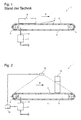
- FIG. 1 shows the standard components of such a vacuum system in which a conveyor belt 2 rotates endlessly on two bearing wheels 3 in a conveying direction S.
- the conveyor belt is provided with holes 4, so that the negative pressure generated in the vacuum chamber 5 can act through the conveyor belt on a corner piece 6 located thereon. Thereby, the workpiece 6 while being conveyed in the conveying direction F can be held on the conveyor belt 2.
- the negative pressure in the vacuum chamber 5 is generated by a suction device 7, which sucks the air from the vacuum chamber 5 through a pipe system and, for example, ejects into the environment.
- a constant negative pressure is maintained in the vacuum chamber 5.
- a disadvantage of this system is that even if there is no workpiece on the conveyor belt, the suction device operates with a constant workload and thus consumes energy unnecessarily.
- EP 2 189 404 A1 discloses a folding machine.
- a vacuum system for a transport device for a To provide a processing device that allows a more economical use of a suction device in the operation of the transport device.
- the transport device comprises a sensor device and a control element by means of which an occupancy ratio between the workpiece and the conveying device or the air-permeable section of the conveying device can be calculated.
- the control device controls the suction device so that it generates a negative pressure under the support surface of the conveyor in dependence on the occupancy ratio. Characterized the idler of the conveyor belt, the suction device is down-regulated to a minimum speed, whereby less energy is consumed during idle operation.
- the suction device runs at maximum speed when the workpiece covers a sufficient area on the conveyor, or on the air-permeable portion of the conveyor, so that the workpiece is held on the suction device. This may be preferred Reaching a certain percentage of the occupancy ratio happen. This ensures that the workpiece is not sucked until it can be held on the conveyor.
- the speed of the suction device decreases steadily, but in particular linearly, starting from the maximum speed, up to an occupancy ratio of 75% -100%. This can further be avoided that the energy consumption is unnecessarily high not only at idle, but the processing device can thereby ensure a constant holding power and be operated economically during operation.
- the suction device runs at an occupancy ratio of 75% -100% with a minimum speed which is greater, but preferably equal to the speed of the suction device at idle of the processing device. This also allows a more economical use of the processing device.
- the speed of the suction device is controlled by the supply of energy and the suction device further preferably comprises a fan.
- the reduction of the rotational speed is preferably carried out along a substantially linear characteristic curve or in stages.
- the structure of a transport device 1 according to the invention is essentially the same as in the prior art. Therefore, the same reference numerals are used for the same parts.
- the transport device 1 is intended for a machining device that performs essentially machining operations (drilling, milling, planing, sawing, grinding, etc.) on preferably plate-shaped workpieces.
- the processing unit 15 present in the processing device is in FIG. 2 schematically as indicated. Such a processing unit 15 may, for example, be a conventional and known CNC processing unit.
- the transport device includes a conveyor such as a conveyor belt 2, which is mounted on at least two rollers 3.
- a roller 3 is preferably a drive roller (see, eg FIG. 2 , the left wheel).
- a vacuum chamber 5 is provided below the conveyor 2, or below the surface of the conveyor 2, on which the workpiece 6 is supported, the negative pressure of which is generated by the suction device 7.
- the device according to the invention additionally has a sensor device 10 which transmits information to a control device 12, such as will be explained in more detail below.
- the control device 12 controls the suction device 7 preferably by means of a frequency converter, which may be part of the sensor device 12, but which may also be located in the suction device 7, then depending on the signals transmitted by the sensor device 10.
- the holding force that acts on the workpieces due to the negative pressure must be sufficiently high due to the machining of the workpieces so that the workpiece can not slip during processing.
- the conveyor belt 2 is designed to be permeable to air. That is, the conveyor belt 2 may be provided with holes 4 or slits over its entire surface, or may also have only one air-permeable portion 8 in which the holes 4 or the slits are inserted into the conveyor belt 2.
- the conveyor belt 2 itself can also have a lattice-like structure or a section 8 with a lattice-like structure or be made of a particularly porous or air-permeable material.
- Such an air-permeable material could be a very durable fabric or a fabric-like material.
- the conveyor belt 2 can also have holes 4, slots or a grid and be coated with an air-permeable material such as a cloth, so that the running on the conveyor belt 2 workpieces 6 are protected by the air-permeable material from damage, for example by a layer of soft material which is placed on the hard conveyor belt surface.
- an air-permeable material such as a cloth
- a suction device 7 for conveying air preferably a pump, a fan, a rotary piston machine or the like, is connected to the vacuum chamber 5 via a flow line 14, for example a pipe, for generating a negative pressure in the vacuum chamber 5.
- the vacuum chamber 5 is preferably designed as a chamber, on its upper side in the same way permeable to air, as previously described for the conveyor belt 2 (holes, slots, etc).
- the vacuum chamber 5 may also have no top.
- the sucked air is then removed via a pressure-side pipe.
- a filter (not shown) is provided which filters dust or other particles from the air.
- the suction device 7 is protected from contamination and does not need to be serviced or checked as often.
- the occupancy ratio is a ratio between the area of all lying on conveyor belt 2 of the transport device 1 workpieces 6 and the surface of the conveyor belt 2 of the transport device. 1
- This sensor device preferably comprises a plurality of touch rollers 10 which detect the contour and / or surface area of the workpiece (see Fig. 3 ).
- the contact rollers 10 preferably extend transversely over the conveyor belt 2. However, in a simplified embodiment, only two sensing rollers may be provided on the two sides of the conveyor belt 2, each running along the side edge of the workpiece.
- the touch rollers 10 are preferably arranged in front of the inlet region of the conveyor belt 2, so that they detect the contour before the workpiece 6 on the conveyor belt 2. In Fig. 3 They are located at the beginning of the conveyor belt, which is also sufficient.
- this ratio is preferably detected by at least one image sensor 10, which is arranged so that it the conveyor belt 2 and in particular the inlet area or initial area of the transport device 1, on which the workpieces 6 first reach the conveyor belt 2, can recognize.
- image sensor 10 it is also possible to provide a plurality of image sensors in the sensor device 10, each of which monitors own sections of the conveyor belt 6 (starting area, middle area, end area) or for different detection purposes (eg for the conveyor belt 2 and for the workpiece 6, respectively) are.
- a sensor device for detecting the occupation ratio would be weight sensors or touch sensors, which are present in the conveyor, preferably in the conveyor belt 2 itself, and which can detect the outline of the workpiece 6 in relation to the uncovered surface of the conveyor belt / air-permeable portion. Combinations of different sensors are conceivable.
- the sensor device 10 may comprise means for calculating the occupancy ratio.
- the surface of the conveyor belt 2 is known, so that the sensor device 10 only has to detect the surface of the workpiece 6 in order to calculate an occupancy ratio.
- the sensor device 10 in addition to the surface of the workpiece 6, also covers the surface of the conveyor belt 2 or preferably only the surface of the air-permeable section 8 (which is shown in FIG FIG. 3 is shown as a grid structure).
- the air-permeable section 8 is essentially only the area through which air can pass. This allows a more accurate adjustment of the negative pressure in the vacuum chamber 5 by the control device, since in fact only the occupied air-permeable surface is taken into account.
- control element 12 may include means which are provided and suitable for calculating the occupancy ratio.
- the Sensor device 10 communicates with this control element 12 and transmits the acquired data or occupancy ratio itself.
- the control element 12 then controls the power of the suction device (usually the speed of the pump, the fan, the rotary machine, etc.) based on the occupancy ratio, so that a pressure proportional to the occupancy ratio negative pressure in the vacuum chamber 5 is generated.
- the suction device 7 is therefore down-regulated to a minimum power / speed M1, since there is no need to produce a higher power for holding a workpiece 6. Thus, there is a minimum negative pressure in the vacuum chamber 5.
- the sensor device 10 detects that a workpiece is on the conveyor belt and calculates an occupancy ratio or passes the acquired information to the control element 12 (which may itself calculate the occupancy ratio).
- the control element 12 then moves the suction device 7 up to the maximum power / speed M max , ie the highest power / speed used in operation, so that a negative pressure arises in the vacuum chamber 5, which is suitable even at a low occupancy ratio. eg 1% -5%) on the conveyor belt with sufficient force.
- the workpiece Depending on the conveying speed, the workpiece then gradually takes up a larger area on the conveyor belt, resulting in a larger occupancy ratio. This is in turn detected by the sensor device 10 and transmitted to the control element 12.
- the control element 12 controls depending on the increasing occupancy ratio, the suction device 7 and the power / speed of the suction device 7 down so that the holding force with which the workpiece 6 is held on the conveyor belt, remains as constant as possible, but it is always large enough to prevent slippage of the workpiece on the conveyor belt prevent.
- the power / speed of the suction device 7 can preferably be controlled via the power supply of the suction device 7.
- the suction device can run at a minimum power / speed M2.
- the minimum power / speed M2 when reaching the limit occupancy ratio is preferably the same as the minimum power / speed M1, as it is in FIG FIG. 4 shows. However, M2 can also be above the minimum speed M1. For example, M2 may exceed the minimum speed M1 by up to 750 rpm or even 500 rpm.
- the decrease in power / speed is preferably carried out substantially linearly, but can also be approximated by a down or up bulging line (see dash-dot lines in FIG Fig.
- FIG. 4b Another preferred embodiment controls the decrease in the rotational speed of the suction device 7 in jumps.
- FIG. 4b 4 jumps are shown as an example, which are each set when reaching a certain occupancy ratio.
- the minimum speed M1 may be, for example, 1500 rpm, the maximum speed M2 3000 rpm and the two jumps to 2000 rpm and 2500 rpm. But there may also be five or more jumps.
- a linear control can be performed, for example, by a jump is performed for each percent of the occupancy ratio (in the case of 100 jumps).
- the range in which the jumps can be carried out can be chosen as desired, it is preferred after starting up to maximum speed that the jumps occur at regular intervals.
- the invention also relates to a method for transporting and holding a workpiece on a conveyor. Such a method could be described as follows:
- the increase in the occupancy ratio decreases starting from the maximum speed M max .
- This method can be combined with particular embodiments of the device according to the invention to form new variants of the method.
Landscapes
- Engineering & Computer Science (AREA)
- Mechanical Engineering (AREA)
- Delivering By Means Of Belts And Rollers (AREA)
- Container, Conveyance, Adherence, Positioning, Of Wafer (AREA)
Priority Applications (1)
| Application Number | Priority Date | Filing Date | Title |
|---|---|---|---|
| PL11182323T PL2433744T3 (pl) | 2010-09-24 | 2011-09-22 | Urządzenie transportowe z systemem próżniowym dla urządzenia obróbkowego |
Applications Claiming Priority (1)
| Application Number | Priority Date | Filing Date | Title |
|---|---|---|---|
| DE202010013582U DE202010013582U1 (de) | 2010-09-24 | 2010-09-24 | Transportvorrichtung für Bearbeitungsvorrichtung von plattenförmigen Werkstücken |
Publications (2)
| Publication Number | Publication Date |
|---|---|
| EP2433744A1 EP2433744A1 (de) | 2012-03-28 |
| EP2433744B1 true EP2433744B1 (de) | 2013-07-10 |
Family
ID=44674550
Family Applications (1)
| Application Number | Title | Priority Date | Filing Date |
|---|---|---|---|
| EP11182323.3A Not-in-force EP2433744B1 (de) | 2010-09-24 | 2011-09-22 | Transportvorrichtung mit Vakuumsystem für eine Bearbeitungsvorrichtung |
Country Status (4)
| Country | Link |
|---|---|
| EP (1) | EP2433744B1 (pl) |
| DE (1) | DE202010013582U1 (pl) |
| ES (1) | ES2429028T3 (pl) |
| PL (1) | PL2433744T3 (pl) |
Families Citing this family (2)
| Publication number | Priority date | Publication date | Assignee | Title |
|---|---|---|---|---|
| DE102017104246B4 (de) | 2017-03-01 | 2022-09-15 | ARRTSM GmbH | Autonome Fertigungsstraße |
| EP4169665B1 (de) | 2021-10-22 | 2024-12-11 | Karl Heesemann Maschinenfabrik GmbH & Co. KG | Werkstückbefestigungsvorrichtung, schleifmaschine und verfahren zur befestigung eines werkstücks |
Family Cites Families (5)
| Publication number | Priority date | Publication date | Assignee | Title |
|---|---|---|---|---|
| DE2939571C2 (de) * | 1979-09-29 | 1982-08-12 | Paul Dipl.-Ing. 6925 Eschelbronn Ernst Jun. | Laufendes Transportband für Schleifmaschinen |
| JP3366787B2 (ja) * | 1995-10-20 | 2003-01-14 | ノーリツ鋼機株式会社 | 感光材料の吸着搬送装置 |
| JP2002332139A (ja) * | 2001-05-10 | 2002-11-22 | Ryobi Ltd | 印刷用紙の搬送装置 |
| DE102008058474A1 (de) * | 2008-11-21 | 2010-05-27 | Heidelberger Druckmaschinen Ag | Falzmaschine |
| DE102008059177B4 (de) | 2008-11-25 | 2010-08-05 | Heesemann, Jürgen, Dipl.-Ing. | Verfahren zum Transportieren eines Werkstücks durch eine Bearbeitungsstation einer Werkstückbearbeitungsvorrichtung und Werkstückbearbeitungsvorrichtung |
-
2010
- 2010-09-24 DE DE202010013582U patent/DE202010013582U1/de not_active Expired - Lifetime
-
2011
- 2011-09-22 EP EP11182323.3A patent/EP2433744B1/de not_active Not-in-force
- 2011-09-22 ES ES11182323T patent/ES2429028T3/es active Active
- 2011-09-22 PL PL11182323T patent/PL2433744T3/pl unknown
Also Published As
| Publication number | Publication date |
|---|---|
| PL2433744T3 (pl) | 2013-11-29 |
| DE202010013582U1 (de) | 2011-12-28 |
| ES2429028T3 (es) | 2013-11-12 |
| EP2433744A1 (de) | 2012-03-28 |
Similar Documents
| Publication | Publication Date | Title |
|---|---|---|
| AT510516B1 (de) | Fertigungszelle mit einer werkteil- transfereinrichtung und transporteinrichtung für werkteile und teileträger | |
| EP3116672B1 (de) | Verfahren zum betreiben einer plattenbearbeitungsanlage | |
| EP0405185B1 (de) | Einrichtung zum Schleifen der Oberfläche von Laminaten | |
| WO2009080328A1 (de) | Verfahren zum bearbeiten einer seitenkante eines paneels und vorrichtung zum durchführen des verfahrens | |
| EP3423232B1 (de) | Vorrichtung mit absaugeinrichtung | |
| EP2476512B1 (de) | Bandabblasvorrichtung | |
| EP3215283B1 (de) | Vorrichtung zum abführen von abluft aus der umgebung eines metallbandes | |
| EP2196416B1 (de) | Verfahren zum Transportieren eines Werkstücks durch eine Bearbeitungs-station einer Werkstückbearbeitungsvorrichtung und Werkstückbearbeitungsvorrichtung | |
| AT501784B1 (de) | Plattenaufteilsäge | |
| EP2433744A1 (de) | Transportvorrichtung mit Vakuumsystem für eine Bearbeitungsvorrichtung | |
| EP2583924B1 (de) | Bogenbearbeitungsmaschine mit Bogenanleger mit Saugbandmodul | |
| EP2802441A1 (de) | Holzbearbeitungsanlage und verfahren zu deren betrieb | |
| EP2602218A2 (de) | Unrundes Saugrad | |
| DE102010055722A1 (de) | Reinigungseinrichtung | |
| WO2013029724A1 (de) | Vorrichtung und verfahren zur filtration mit einem bandförmigen filtermedium | |
| DE102024113154A1 (de) | Energieeffizientes Vakuumtransportband | |
| EP2551219A1 (de) | Werkstücktransportsystem | |
| DE102016014268B4 (de) | Vorrichtung und Verfahren zum Trennen von Pressgutmatten | |
| DE102018002444B9 (de) | Verfahren und Einrichtung zum Zuführen von Kühlmittel an einer Schleifmaschine | |
| EP0293574A2 (de) | Bandschleifmaschine | |
| EP1925412B1 (de) | Kantenbearbeitungsaggregat | |
| DE20205262U1 (de) | Schleifmaschine | |
| AT13518U1 (de) | Vorrichtung zur Entlüftung eines auf eine Faserbahn aufzutragenden Beschichtungsmediums | |
| DE69000587T2 (de) | Topf-zufuehrvorrichtung. | |
| EP3441172B1 (de) | Verfahren zum auftrennen länglicher werkstücke sowie bearbeitungsmaschine zur durchführung eines solchen verfahrens |
Legal Events
| Date | Code | Title | Description |
|---|---|---|---|
| PUAI | Public reference made under article 153(3) epc to a published international application that has entered the european phase |
Free format text: ORIGINAL CODE: 0009012 |
|
| AK | Designated contracting states |
Kind code of ref document: A1 Designated state(s): AL AT BE BG CH CY CZ DE DK EE ES FI FR GB GR HR HU IE IS IT LI LT LU LV MC MK MT NL NO PL PT RO RS SE SI SK SM TR |
|
| AX | Request for extension of the european patent |
Extension state: BA ME |
|
| 17P | Request for examination filed |
Effective date: 20120828 |
|
| GRAP | Despatch of communication of intention to grant a patent |
Free format text: ORIGINAL CODE: EPIDOSNIGR1 |
|
| RIC1 | Information provided on ipc code assigned before grant |
Ipc: B24B 27/06 20060101ALI20130128BHEP Ipc: B65H 7/02 20060101ALI20130128BHEP Ipc: B24B 41/06 20120101ALI20130128BHEP Ipc: B65G 21/20 20060101ALI20130128BHEP Ipc: B23Q 7/03 20060101AFI20130128BHEP |
|
| RAP1 | Party data changed (applicant data changed or rights of an application transferred) |
Owner name: WEEKE BOHRSYSTEME GMBH |
|
| GRAS | Grant fee paid |
Free format text: ORIGINAL CODE: EPIDOSNIGR3 |
|
| GRAA | (expected) grant |
Free format text: ORIGINAL CODE: 0009210 |
|
| AK | Designated contracting states |
Kind code of ref document: B1 Designated state(s): AL AT BE BG CH CY CZ DE DK EE ES FI FR GB GR HR HU IE IS IT LI LT LU LV MC MK MT NL NO PL PT RO RS SE SI SK SM TR |
|
| REG | Reference to a national code |
Ref country code: GB Ref legal event code: FG4D Free format text: NOT ENGLISH |
|
| REG | Reference to a national code |
Ref country code: AT Ref legal event code: REF Ref document number: 620662 Country of ref document: AT Kind code of ref document: T Effective date: 20130715 Ref country code: CH Ref legal event code: EP |
|
| REG | Reference to a national code |
Ref country code: IE Ref legal event code: FG4D Free format text: LANGUAGE OF EP DOCUMENT: GERMAN |
|
| REG | Reference to a national code |
Ref country code: DE Ref legal event code: R096 Ref document number: 502011001009 Country of ref document: DE Effective date: 20130912 |
|
| PG25 | Lapsed in a contracting state [announced via postgrant information from national office to epo] |
Ref country code: SI Free format text: LAPSE BECAUSE OF FAILURE TO SUBMIT A TRANSLATION OF THE DESCRIPTION OR TO PAY THE FEE WITHIN THE PRESCRIBED TIME-LIMIT Effective date: 20130710 |
|
| REG | Reference to a national code |
Ref country code: ES Ref legal event code: FG2A Ref document number: 2429028 Country of ref document: ES Kind code of ref document: T3 Effective date: 20131112 |
|
| REG | Reference to a national code |
Ref country code: PL Ref legal event code: T3 |
|
| REG | Reference to a national code |
Ref country code: NL Ref legal event code: VDEP Effective date: 20130710 |
|
| REG | Reference to a national code |
Ref country code: LT Ref legal event code: MG4D |
|
| PG25 | Lapsed in a contracting state [announced via postgrant information from national office to epo] |
Ref country code: HR Free format text: LAPSE BECAUSE OF FAILURE TO SUBMIT A TRANSLATION OF THE DESCRIPTION OR TO PAY THE FEE WITHIN THE PRESCRIBED TIME-LIMIT Effective date: 20130710 Ref country code: SE Free format text: LAPSE BECAUSE OF FAILURE TO SUBMIT A TRANSLATION OF THE DESCRIPTION OR TO PAY THE FEE WITHIN THE PRESCRIBED TIME-LIMIT Effective date: 20130710 Ref country code: NO Free format text: LAPSE BECAUSE OF FAILURE TO SUBMIT A TRANSLATION OF THE DESCRIPTION OR TO PAY THE FEE WITHIN THE PRESCRIBED TIME-LIMIT Effective date: 20131010 Ref country code: PT Free format text: LAPSE BECAUSE OF FAILURE TO SUBMIT A TRANSLATION OF THE DESCRIPTION OR TO PAY THE FEE WITHIN THE PRESCRIBED TIME-LIMIT Effective date: 20131111 Ref country code: LT Free format text: LAPSE BECAUSE OF FAILURE TO SUBMIT A TRANSLATION OF THE DESCRIPTION OR TO PAY THE FEE WITHIN THE PRESCRIBED TIME-LIMIT Effective date: 20130710 Ref country code: CY Free format text: LAPSE BECAUSE OF FAILURE TO SUBMIT A TRANSLATION OF THE DESCRIPTION OR TO PAY THE FEE WITHIN THE PRESCRIBED TIME-LIMIT Effective date: 20130814 Ref country code: IS Free format text: LAPSE BECAUSE OF FAILURE TO SUBMIT A TRANSLATION OF THE DESCRIPTION OR TO PAY THE FEE WITHIN THE PRESCRIBED TIME-LIMIT Effective date: 20131110 |
|
| PG25 | Lapsed in a contracting state [announced via postgrant information from national office to epo] |
Ref country code: FI Free format text: LAPSE BECAUSE OF FAILURE TO SUBMIT A TRANSLATION OF THE DESCRIPTION OR TO PAY THE FEE WITHIN THE PRESCRIBED TIME-LIMIT Effective date: 20130710 Ref country code: NL Free format text: LAPSE BECAUSE OF FAILURE TO SUBMIT A TRANSLATION OF THE DESCRIPTION OR TO PAY THE FEE WITHIN THE PRESCRIBED TIME-LIMIT Effective date: 20130710 Ref country code: GR Free format text: LAPSE BECAUSE OF FAILURE TO SUBMIT A TRANSLATION OF THE DESCRIPTION OR TO PAY THE FEE WITHIN THE PRESCRIBED TIME-LIMIT Effective date: 20131011 Ref country code: LV Free format text: LAPSE BECAUSE OF FAILURE TO SUBMIT A TRANSLATION OF THE DESCRIPTION OR TO PAY THE FEE WITHIN THE PRESCRIBED TIME-LIMIT Effective date: 20130710 |
|
| BERE | Be: lapsed |
Owner name: WEEKE BOHRSYSTEME G.M.B.H. Effective date: 20130930 |
|
| PG25 | Lapsed in a contracting state [announced via postgrant information from national office to epo] |
Ref country code: CY Free format text: LAPSE BECAUSE OF FAILURE TO SUBMIT A TRANSLATION OF THE DESCRIPTION OR TO PAY THE FEE WITHIN THE PRESCRIBED TIME-LIMIT Effective date: 20130710 |
|
| PG25 | Lapsed in a contracting state [announced via postgrant information from national office to epo] |
Ref country code: EE Free format text: LAPSE BECAUSE OF FAILURE TO SUBMIT A TRANSLATION OF THE DESCRIPTION OR TO PAY THE FEE WITHIN THE PRESCRIBED TIME-LIMIT Effective date: 20130710 Ref country code: DK Free format text: LAPSE BECAUSE OF FAILURE TO SUBMIT A TRANSLATION OF THE DESCRIPTION OR TO PAY THE FEE WITHIN THE PRESCRIBED TIME-LIMIT Effective date: 20130710 Ref country code: MC Free format text: LAPSE BECAUSE OF FAILURE TO SUBMIT A TRANSLATION OF THE DESCRIPTION OR TO PAY THE FEE WITHIN THE PRESCRIBED TIME-LIMIT Effective date: 20130710 Ref country code: CZ Free format text: LAPSE BECAUSE OF FAILURE TO SUBMIT A TRANSLATION OF THE DESCRIPTION OR TO PAY THE FEE WITHIN THE PRESCRIBED TIME-LIMIT Effective date: 20130710 Ref country code: RO Free format text: LAPSE BECAUSE OF FAILURE TO SUBMIT A TRANSLATION OF THE DESCRIPTION OR TO PAY THE FEE WITHIN THE PRESCRIBED TIME-LIMIT Effective date: 20130710 Ref country code: SK Free format text: LAPSE BECAUSE OF FAILURE TO SUBMIT A TRANSLATION OF THE DESCRIPTION OR TO PAY THE FEE WITHIN THE PRESCRIBED TIME-LIMIT Effective date: 20130710 |
|
| PLBE | No opposition filed within time limit |
Free format text: ORIGINAL CODE: 0009261 |
|
| STAA | Information on the status of an ep patent application or granted ep patent |
Free format text: STATUS: NO OPPOSITION FILED WITHIN TIME LIMIT |
|
| 26N | No opposition filed |
Effective date: 20140411 |
|
| REG | Reference to a national code |
Ref country code: IE Ref legal event code: MM4A |
|
| REG | Reference to a national code |
Ref country code: DE Ref legal event code: R097 Ref document number: 502011001009 Country of ref document: DE Effective date: 20140411 |
|
| PG25 | Lapsed in a contracting state [announced via postgrant information from national office to epo] |
Ref country code: BE Free format text: LAPSE BECAUSE OF NON-PAYMENT OF DUE FEES Effective date: 20130930 Ref country code: IE Free format text: LAPSE BECAUSE OF NON-PAYMENT OF DUE FEES Effective date: 20130922 |
|
| REG | Reference to a national code |
Ref country code: CH Ref legal event code: PL |
|
| PG25 | Lapsed in a contracting state [announced via postgrant information from national office to epo] |
Ref country code: SM Free format text: LAPSE BECAUSE OF FAILURE TO SUBMIT A TRANSLATION OF THE DESCRIPTION OR TO PAY THE FEE WITHIN THE PRESCRIBED TIME-LIMIT Effective date: 20130710 |
|
| PG25 | Lapsed in a contracting state [announced via postgrant information from national office to epo] |
Ref country code: TR Free format text: LAPSE BECAUSE OF FAILURE TO SUBMIT A TRANSLATION OF THE DESCRIPTION OR TO PAY THE FEE WITHIN THE PRESCRIBED TIME-LIMIT Effective date: 20130710 Ref country code: MT Free format text: LAPSE BECAUSE OF FAILURE TO SUBMIT A TRANSLATION OF THE DESCRIPTION OR TO PAY THE FEE WITHIN THE PRESCRIBED TIME-LIMIT Effective date: 20130710 |
|
| PG25 | Lapsed in a contracting state [announced via postgrant information from national office to epo] |
Ref country code: HU Free format text: LAPSE BECAUSE OF FAILURE TO SUBMIT A TRANSLATION OF THE DESCRIPTION OR TO PAY THE FEE WITHIN THE PRESCRIBED TIME-LIMIT; INVALID AB INITIO Effective date: 20110922 Ref country code: LU Free format text: LAPSE BECAUSE OF NON-PAYMENT OF DUE FEES Effective date: 20130922 Ref country code: CH Free format text: LAPSE BECAUSE OF NON-PAYMENT OF DUE FEES Effective date: 20140930 Ref country code: MK Free format text: LAPSE BECAUSE OF FAILURE TO SUBMIT A TRANSLATION OF THE DESCRIPTION OR TO PAY THE FEE WITHIN THE PRESCRIBED TIME-LIMIT Effective date: 20130710 Ref country code: RS Free format text: LAPSE BECAUSE OF FAILURE TO SUBMIT A TRANSLATION OF THE DESCRIPTION OR TO PAY THE FEE WITHIN THE PRESCRIBED TIME-LIMIT Effective date: 20131010 Ref country code: LI Free format text: LAPSE BECAUSE OF NON-PAYMENT OF DUE FEES Effective date: 20140930 Ref country code: BG Free format text: LAPSE BECAUSE OF FAILURE TO SUBMIT A TRANSLATION OF THE DESCRIPTION OR TO PAY THE FEE WITHIN THE PRESCRIBED TIME-LIMIT Effective date: 20130710 |
|
| GBPC | Gb: european patent ceased through non-payment of renewal fee |
Effective date: 20150922 |
|
| PG25 | Lapsed in a contracting state [announced via postgrant information from national office to epo] |
Ref country code: GB Free format text: LAPSE BECAUSE OF NON-PAYMENT OF DUE FEES Effective date: 20150922 |
|
| REG | Reference to a national code |
Ref country code: FR Ref legal event code: PLFP Year of fee payment: 6 |
|
| REG | Reference to a national code |
Ref country code: FR Ref legal event code: PLFP Year of fee payment: 7 |
|
| REG | Reference to a national code |
Ref country code: AT Ref legal event code: MM01 Ref document number: 620662 Country of ref document: AT Kind code of ref document: T Effective date: 20160922 |
|
| PG25 | Lapsed in a contracting state [announced via postgrant information from national office to epo] |
Ref country code: AT Free format text: LAPSE BECAUSE OF NON-PAYMENT OF DUE FEES Effective date: 20160922 |
|
| REG | Reference to a national code |
Ref country code: FR Ref legal event code: PLFP Year of fee payment: 8 |
|
| PG25 | Lapsed in a contracting state [announced via postgrant information from national office to epo] |
Ref country code: AL Free format text: LAPSE BECAUSE OF FAILURE TO SUBMIT A TRANSLATION OF THE DESCRIPTION OR TO PAY THE FEE WITHIN THE PRESCRIBED TIME-LIMIT Effective date: 20130710 |
|
| PGFP | Annual fee paid to national office [announced via postgrant information from national office to epo] |
Ref country code: IT Payment date: 20210915 Year of fee payment: 11 Ref country code: FR Payment date: 20210914 Year of fee payment: 11 |
|
| PGFP | Annual fee paid to national office [announced via postgrant information from national office to epo] |
Ref country code: PL Payment date: 20210809 Year of fee payment: 11 Ref country code: DE Payment date: 20210914 Year of fee payment: 11 |
|
| PGFP | Annual fee paid to national office [announced via postgrant information from national office to epo] |
Ref country code: ES Payment date: 20211001 Year of fee payment: 11 |
|
| REG | Reference to a national code |
Ref country code: DE Ref legal event code: R119 Ref document number: 502011001009 Country of ref document: DE |
|
| PG25 | Lapsed in a contracting state [announced via postgrant information from national office to epo] |
Ref country code: FR Free format text: LAPSE BECAUSE OF NON-PAYMENT OF DUE FEES Effective date: 20220930 Ref country code: DE Free format text: LAPSE BECAUSE OF NON-PAYMENT OF DUE FEES Effective date: 20230401 |
|
| REG | Reference to a national code |
Ref country code: ES Ref legal event code: FD2A Effective date: 20231030 |
|
| PG25 | Lapsed in a contracting state [announced via postgrant information from national office to epo] |
Ref country code: IT Free format text: LAPSE BECAUSE OF NON-PAYMENT OF DUE FEES Effective date: 20220922 |
|
| PG25 | Lapsed in a contracting state [announced via postgrant information from national office to epo] |
Ref country code: PL Free format text: LAPSE BECAUSE OF NON-PAYMENT OF DUE FEES Effective date: 20220922 |
|
| PG25 | Lapsed in a contracting state [announced via postgrant information from national office to epo] |
Ref country code: ES Free format text: LAPSE BECAUSE OF NON-PAYMENT OF DUE FEES Effective date: 20220923 |
|
| PG25 | Lapsed in a contracting state [announced via postgrant information from national office to epo] |
Ref country code: ES Free format text: LAPSE BECAUSE OF NON-PAYMENT OF DUE FEES Effective date: 20220923 |