EP2433552B1 - Light source apparatus and endoscope system - Google Patents
Light source apparatus and endoscope system Download PDFInfo
- Publication number
- EP2433552B1 EP2433552B1 EP11765359A EP11765359A EP2433552B1 EP 2433552 B1 EP2433552 B1 EP 2433552B1 EP 11765359 A EP11765359 A EP 11765359A EP 11765359 A EP11765359 A EP 11765359A EP 2433552 B1 EP2433552 B1 EP 2433552B1
- Authority
- EP
- European Patent Office
- Prior art keywords
- light
- filter
- wavelength band
- imaging
- section
- Prior art date
- Legal status (The legal status is an assumption and is not a legal conclusion. Google has not performed a legal analysis and makes no representation as to the accuracy of the status listed.)
- Not-in-force
Links
Images


Classifications
-
- A—HUMAN NECESSITIES
- A61—MEDICAL OR VETERINARY SCIENCE; HYGIENE
- A61B—DIAGNOSIS; SURGERY; IDENTIFICATION
- A61B1/00—Instruments for performing medical examinations of the interior of cavities or tubes of the body by visual or photographical inspection, e.g. endoscopes; Illuminating arrangements therefor
- A61B1/06—Instruments for performing medical examinations of the interior of cavities or tubes of the body by visual or photographical inspection, e.g. endoscopes; Illuminating arrangements therefor with illuminating arrangements
- A61B1/0638—Instruments for performing medical examinations of the interior of cavities or tubes of the body by visual or photographical inspection, e.g. endoscopes; Illuminating arrangements therefor with illuminating arrangements providing two or more wavelengths
-
- A—HUMAN NECESSITIES
- A61—MEDICAL OR VETERINARY SCIENCE; HYGIENE
- A61B—DIAGNOSIS; SURGERY; IDENTIFICATION
- A61B1/00—Instruments for performing medical examinations of the interior of cavities or tubes of the body by visual or photographical inspection, e.g. endoscopes; Illuminating arrangements therefor
- A61B1/04—Instruments for performing medical examinations of the interior of cavities or tubes of the body by visual or photographical inspection, e.g. endoscopes; Illuminating arrangements therefor combined with photographic or television appliances
- A61B1/043—Instruments for performing medical examinations of the interior of cavities or tubes of the body by visual or photographical inspection, e.g. endoscopes; Illuminating arrangements therefor combined with photographic or television appliances for fluorescence imaging
-
- A—HUMAN NECESSITIES
- A61—MEDICAL OR VETERINARY SCIENCE; HYGIENE
- A61B—DIAGNOSIS; SURGERY; IDENTIFICATION
- A61B1/00—Instruments for performing medical examinations of the interior of cavities or tubes of the body by visual or photographical inspection, e.g. endoscopes; Illuminating arrangements therefor
- A61B1/06—Instruments for performing medical examinations of the interior of cavities or tubes of the body by visual or photographical inspection, e.g. endoscopes; Illuminating arrangements therefor with illuminating arrangements
- A61B1/063—Instruments for performing medical examinations of the interior of cavities or tubes of the body by visual or photographical inspection, e.g. endoscopes; Illuminating arrangements therefor with illuminating arrangements for monochromatic or narrow-band illumination
-
- A—HUMAN NECESSITIES
- A61—MEDICAL OR VETERINARY SCIENCE; HYGIENE
- A61B—DIAGNOSIS; SURGERY; IDENTIFICATION
- A61B1/00—Instruments for performing medical examinations of the interior of cavities or tubes of the body by visual or photographical inspection, e.g. endoscopes; Illuminating arrangements therefor
- A61B1/06—Instruments for performing medical examinations of the interior of cavities or tubes of the body by visual or photographical inspection, e.g. endoscopes; Illuminating arrangements therefor with illuminating arrangements
- A61B1/0646—Instruments for performing medical examinations of the interior of cavities or tubes of the body by visual or photographical inspection, e.g. endoscopes; Illuminating arrangements therefor with illuminating arrangements with illumination filters
-
- A—HUMAN NECESSITIES
- A61—MEDICAL OR VETERINARY SCIENCE; HYGIENE
- A61B—DIAGNOSIS; SURGERY; IDENTIFICATION
- A61B1/00—Instruments for performing medical examinations of the interior of cavities or tubes of the body by visual or photographical inspection, e.g. endoscopes; Illuminating arrangements therefor
- A61B1/06—Instruments for performing medical examinations of the interior of cavities or tubes of the body by visual or photographical inspection, e.g. endoscopes; Illuminating arrangements therefor with illuminating arrangements
- A61B1/0655—Control therefor
-
- A—HUMAN NECESSITIES
- A61—MEDICAL OR VETERINARY SCIENCE; HYGIENE
- A61B—DIAGNOSIS; SURGERY; IDENTIFICATION
- A61B1/00—Instruments for performing medical examinations of the interior of cavities or tubes of the body by visual or photographical inspection, e.g. endoscopes; Illuminating arrangements therefor
- A61B1/00002—Operational features of endoscopes
- A61B1/00004—Operational features of endoscopes characterised by electronic signal processing
- A61B1/00009—Operational features of endoscopes characterised by electronic signal processing of image signals during a use of endoscope
- A61B1/000094—Operational features of endoscopes characterised by electronic signal processing of image signals during a use of endoscope extracting biological structures
Definitions
- the present invention relates to a light source apparatus which supplies illuminating light to a medical endoscope inserted into a subject for observing a tissue in a body and an endoscope system having the light source apparatus, and more particularly, to a light source apparatus that supplies illuminating light for white light imaging and special light imaging, and an endoscope system having the light source apparatus.
- medical endoscopes require a light source apparatus for illuminating the interior of the body. Illuminating light generated by the light source apparatus illuminates a target tissue from a distal end portion where an image pickup section is located via a light guide which is inserted into an insertion portion of the endoscope.
- normal light imaging using visible light (white light imaging: WLI) is generally performed and various kinds of special light imaging utilizing wavelength characteristics of irradiating light are also performed.
- WLI white light imaging
- Japanese Patent Application Laid-Open Publication No. 2007-29453 discloses a frame-sequential endoscope system to perform narrow band imaging, auto fluorescence imaging and infrared imaging or the like as special light imaging.
- NBI narrow band imaging
- excitation light for observing fluorescence from a fluorescent substance such as collagen and light of a wavelength absorbed by hemoglobin in the blood are sequentially radiated to highlight a tumorous lesion and a normal mucous membrane with different color tones.
- IRI infrared imaging
- ICG indocyanine green
- Japanese Patent Application Laid-Open Publication No. 2007-29453 discloses the use of irradiating light passing through a normal red, green or blue primary color filter and a filter that passes light of a relatively wide wavelength band to prevent damage to an endoscope by heat of infrared light.
- An object of the present invention is to provide a light source apparatus capable of obtaining a bright image in a case of a special light imaging and an endoscope system including the light source apparatus.
- US 2005/0078175 A1 discloses an endoscopic image processing apparatus wherein a raw image and a processed image having several colors assigned to IHb values, which correspond to hematic information, are generated from a signal produced by a CCD incorporated in an electronic endoscope.
- US 2005/096505 discloses an image processing apparatus comprising a color balance adjustment unit for adjusting the color balance of image signals obtained by picking up an image of an object through an image pickup unit.
- US 2002/177751 discloses a light source unit with a switchable filter section in which an RGB filter and a fluorescence observation filter are shifted into the light path.
- a light source apparatus of an embodiment that can supply illuminating light for normal light imaging and special light imaging includes a light source section that generates wideband light, a first rotational filter section that can place a first filter that passes light of a first wavelength band, a second filter that passes light of a second wavelength band having a longer wavelength than the first wavelength band or a third filter that passes light of a third wavelength band having a longer wavelength than the second wavelength band and light of the first wavelength band in a light path of the wideband light generated by the light source section, a second rotational filter section that can place a fourth filter that passes light of the second wavelength band and light of the third wavelength band in the light path, and a band selection filter section that can place a band limiting filter that limits light of the first wavelength band and light of the second wavelength band to a narrow band and intercepts light of the third wavelength band in the light path, wherein in a case of the normal light imaging, the first rotational filter section and the second rotational filter section are controllable so that the fourth
- An endoscope system 1 can perform narrow band imaging as special light imaging in addition to normal light imaging. That is, as shown in Fig. 1 , the endoscope system 1 has a light source apparatus 20 that can alternatively supply illuminating light for normal light imaging and narrow band imaging, a main unit 10 and an endoscope 30.
- the endoscope 30 includes an operation section 32, an elongated insertion portion 33 inserted into the digestive tract or the like of a subject and a universal cable 31.
- a distal end portion 33A of the insertion portion 33 is provided with an image pickup optical section 37, a CCD 35 which is a frame-sequential image pickup section and an illuminating optical section 36 that emits illuminating light.
- the illuminating light from the light source apparatus 20 is guided to the illuminating optical section 36 through a light guide 34 that passes through the insertion portion 33.
- a cut filter 38 is placed in a light path of the image pickup optical section 37 to cut unnecessary reflected light as required.
- the light source apparatus 20 includes a xenon lamp 21 which is a light source section, a band selection filter section 22, a rotational filter unit 25 made up of a first rotational filter section 23 and a second rotational filter section 24 and optical sections 26A, 26B and 26C, and supplies wideband light generated by the xenon lamp 21 to the light guide 34 as illuminating light according to an observation mode.
- the optical sections 26A, 26B and 26C are lenses to control luminous flux of illuminating light.
- the light source section is not limited to the xenon lamp 21 as long as it is a light source that generates wideband light ranging from visible light to infrared light.
- the xenon lamp 21 is provided with a mirror 21A which also reflects light generated in a rear direction forward.
- the main unit 10 has an image processing unit 12, a changeover switch 13 for the operator to select an observation mode and a control section 11 that controls the endoscope system 1 as a whole, and has a monitor 14 connected thereto.
- the image processing unit 12 having a signal amplification circuit (AGC) 12A synthesizes a plurality of images of a subject by illuminating light via different color filters after brightness adjustment and outputs a color image or pseudo-color image.
- AGC signal amplification circuit
- the changeover switch 13 may also be provided in the operation section 32.
- the band selection filter section 22 is a turret that has a plurality of band limiting filters (band-pass filters) 22a to 22d in openings of a metal disk and can place a band limiting filter for a selected observation mode in a light path LP by rotating around the axis of rotation.
- the band limiting filter 22a is a UV-IR cut filter
- the band limiting filter 22b is a composite filter made up of two filters
- the band limiting filter 22c is a composite filter made up of two filters
- an AFI filter and a UV-IR cut filter and the band limiting filter 22d is an IRI filter.
- the band selection filter section 22 may also be a band selection filter section that has two independently rotatable metal disks and combines respective metal disk filters to be used as a composite filter.
- the first rotational filter section 23 arranges a blue (B) filter 23a which is a first filter that passes light of a blue wavelength band, a green (G) filter 23b which is a second filter that passes light of a green wavelength band and a magenta (Mg) filter 23c which is a third filter that passes light of red and blue wavelength bands in three arc-shaped openings on the same circumference of a metal disk.
- the second rotational filter section 24 arranges a yellow (Ye) filter 24a which is a fourth filter that passes light of green and red wavelength bands in one of arc-shaped openings on the same circumference of a metal disk.
- the B filter 23a and the G filter 23b are primary color filters and the Mg filter 23c and the Ye filter 24a are complementary color filters.
- the first rotational filter section 23 and the second rotational filter section 24 of the rotational filter unit 25 continuously rotate around the same axis of rotation and illuminating light beams of their respective colors are thereby sequentially radiated onto the subject. There may also be an opening that passes all visible light beams.
- the rotational filter unit 25 can control a filter placed in the light path LP by the first rotational filter section 23 and the second rotational filter section 24 simultaneously. In other words, the control section 11 controls the first rotational filter section 23 and the second rotational filter section 24 as described above.
- control section 11 performs control such that relative positions in the rotation direction of the second rotational filter section 24 and the first rotational filter section 23 are set to predetermined positions and then fixes the second rotational filter section 24 and the first rotational filter section 23. For this reason, when the first rotational filter section 23 rotates, the second rotational filter section 24 fixed to the first rotational filter section 23 also rotates simultaneously.
- the first rotational filter section 23 and the second rotational filter section 24 may also be able to rotate independently of each other as long as these filter sections can be subjected to synchronous control, that is, matched phase rotation control.
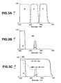
- Fig. 3A to Fig. 3C are graphs illustrating transmission characteristics of the filters of the rotation unit, and the horizontal axis represents a wavelength and the vertical axis represents a transmittance.
- Fig. 3A shows transmission characteristics of three primary color filters that pass red (R), green (G) and blue (B) light beams respectively
- Fig. 3B shows a transmission characteristic of an NBI filter that limits blue light (B) and green light (G) to discrete narrow band light beams (nB, nG) and also intercepts red light
- Fig. 3C shows a transmission characteristic of a UV-IR cut filter that intercepts light other than the visible light region and a transmission characteristic when the NBI filter and the UV-IR cut filter are combined.
- the transmittance of the B filter 23a is 50% or above at 495 nm or below and 93% or above at 480 nm or below.
- the transmittance of the G filter 23b is 50% or above at 500 to 575 nm and 93% or above at 515 to 560 nm.
- the transmittance of the R filter is 50% or above at 585 to 655 nm and 93% or above at 600 to 640 nm.
- the transmittance of the NBI filter is 50% or above at 445 nm or below and less than 1% at 455 nm to 510 nm, but is higher again at 520 to 560 nm.
- Fig. 3A the transmittance of the B filter 23a is 50% or above at 495 nm or below and 93% or above at 480 nm or below.
- the transmittance of the G filter 23b is 50% or above at 500 to 575 nm and 93% or above at 515 to 560 nm.
- the UV-IR cut filter passes light of the visible light region (400 to 675 nm).
- the upper limit or lower limit may be at least an upper limit or lower limit of the visible light region.
- Fig. 4A and Fig. 4B are diagrams illustrating a relationship between a filter placed in the light path LP of the frame-sequential endoscope system and irradiating light, and the horizontal axis represents a time.
- a UV-IR cut filter of the band selection filter section is always placed in the light path LP and light outside the visible light region is intercepted.
- illuminating light is intermittently intercepted and red (R), green (G) and blue (B) beams are sequentially and continuously radiated onto the subject.
- Three images of the subject obtained per color are time-sequentially picked up by the CCD 35, synthesized in the image processing unit 12 and displayed on the monitor 14 as one color image.
- the frame rate of a moving image is determined by the rotation speed of the rotational filter.
- narrow band imaging NBI
- the NBI filter and the UV-IR cut filter of the band selection filter section are always placed in the light path LP.
- narrow band blue light (nB) and narrow band green light (nG) are sequentially and continuously radiated onto the subject.
- Two images obtained by narrow band blue light (nB) and narrow band green light (nG) are synthesized and displayed on the monitor as a pseudo-color image.
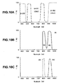
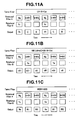
- the first rotational filter section 23 of the rotational filter unit 25 is provided with the B filter 23a, the G filter 23b and the Mg filter 23c having the transmission characteristics shown in Fig. 5A and the second rotational filter section 24 is provided with the Ye filter 24a having the transmission characteristic shown in Fig. 5B .
- the control section 11 controls the first and second rotational filter sections 23 and 24 (rotational filter unit 25) such that the Ye filter 24a of the second rotational filter section 24 is placed in the light path LP when the Mg filter 23c of the first rotational filter section 23 is placed in the light path LP. That is, when normal light imaging is selected through operation of the mode changeover SW 13 by the operator, the control section 11 rotates the Ye filter 24a of the second rotational filter section 24 to a position where the Ye filter 24a overlaps with the Mg filter 23c of the first rotational filter section 23, and then fixes the second rotational filter section 24 and the first rotational filter section 23. The control section 11 then continuously rotates the first rotational filter section 23. In the light source apparatus 20, the openings 24b and 24c of the second rotational filter section 24 are cavities.
- Fig. 6A in normal light imaging (WLI), when the first rotational filter section 23 and the second rotational filter section 24 continuously rotate, illuminating light is intermittently intercepted and red R1, green (G) and blue (B) light beams are sequentially radiated onto the subject.
- Three images of the subject obtained per color by the image pickup section black and white images with only a brightness signal) are time-sequentially picked up by the CCD 35, synthesized by the image processing unit 12 and displayed on the monitor 14 as one color image.
- red R1 is irradiating light that passes through the Mg filter 23c and the Ye filter 24a. That is, as shown in Fig. 5A , the irradiating light that passes through the Mg filter 23c includes light of a blue wavelength band and light of a red wavelength band, and becomes light of a red wavelength band (red R1) by further passing through the Ye filter 24a.
- narrow band imaging the NBI filter ( Fig. 3C ) in the band selection filter section 22 is placed in the light path LP and the first and second rotational filter sections 23 and 24 are controlled such that the Ye filter 24a of the second rotational filter section 24 is placed in the light path LP when the G filter 23b of the first rotational filter section 23 is placed in the light path LP. That is, when narrow band imaging is selected through the operation of the mode changeover SW 13, the control section 11 rotates the second rotational filter section 24 to a position where the G filter 23b and the Ye filter 24a overlap with each other and fixes the second rotational filter section 24. The control section 11 then controls the first rotational filter section 23 so as to continuously rotate.
- narrow band blue light (nB1), narrow band green light (nG1) and narrow band blue light (nB) are sequentially radiated onto the subject.
- the narrow band blue light (nB1) is irradiating light that has passed through the NBI filter and the Mg filter 23c
- the narrow band green light (nG1) is irradiating light that has passed through the NBI filter, the G filter 23b and the Ye filter 24a.
- the image processing unit 12 applies addition processing to the image obtained by narrow band blue light (nB1) and the image obtained by narrow band blue light (nB), and can thereby obtain a brighter narrow band blue light image. That is, the endoscope system 1 can make brighter a narrow band blue light image which is darker in the conventional endoscope system than an image obtained by narrow band green light (nG1) by applying addition processing to the two images. For this reason, the endoscope system 1 can cause the monitor 14 to display a pseudo-color image of high image quality achieving a balance between narrow band green light (nG1) and narrow band blue light (nB+nB1).
- the half width wavelength (Mg50) in the blue region of the Mg filter 23c is 465 nm and is located on the shorter wavelength side than the half width wavelength (B50) 495 nm on the longer wavelength side of the B filter 23a.
- the half width wavelength refers to a wavelength where the transmittance becomes 50%.
- the difference between the half width wavelength (Mg50) of 465 nm in the blue region of the Mg filter 23c and the half width wavelength (Ye50) of 510 nm on the shorter wavelength side of the Ye filter 24a shown in Fig. 5B is 45 nm, which falls within a range of 30 to 70 nm.
- the light source apparatus 20 can supply light in a desired wavelength region.
- the light source apparatus 20 can obtain a brighter image in narrow band imaging and the endoscope system 1 provided with the light source apparatus 20 can obtain a brighter image in narrow band imaging.
- an endoscope system 1A and a light source apparatus 20A according to a modification example of the first embodiment will be described. Since the endoscope system 1A or the like of the present modification example is similar to the endoscope system 1 or the like of the first embodiment, the same components will be assigned the same reference numerals and descriptions thereof will be omitted.
- the current of the xenon lamp 21 of a light source apparatus 20A may be increased or a diaphragm (not shown) may be adjusted to increase the basic light quantity.
- a signal may be amplified more by increasing an amplification factor (gain) of an auto gain control (AGC) circuit 12A of the image processing unit 12.
- AGC auto gain control
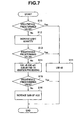
- the image processing unit 12 decides whether brightness of an acquired image is a predetermined value or above.
- the image processing unit 12 synthesizes only an image obtained by narrow band blue light (nB) with an image obtained by narrow band green light (nG1) and creates a pseudo-color image. That is, the image obtained by narrow band blue light (nB1) is discarded.
- the image obtained by narrow band blue light (nB) is different from the image obtained by narrow band blue light (nB1) in the image pickup time, and therefore using the image obtained by narrow band blue light (nB1) for a synthesis may cause image quality to deteriorate.
- the image obtained by narrow band blue light (nB1) may be used and the image obtained by narrow band blue light (nB) may be discarded instead.
- the control section 11 increases the current of the xenon lamp 21 or adjusts the diaphragm (not shown) to increase the basic light quantity of the light source apparatus 20.
- a predetermined value S10: No
- the control section 11 increases the current of the xenon lamp 21 or adjusts the diaphragm (not shown) to increase the basic light quantity of the light source apparatus 20.
- the image processing unit 12 decides whether the brightness of the acquired image is a predetermined value or above. When the brightness of the image is a predetermined value or above (S 13: Yes), in S11, the image processing unit 12 synthesizes only the image obtained by narrow band blue light (nB) with the image obtained by narrow band green light (nG1) to create a pseudo-color image.
- nB narrow band blue light
- nG1 narrow band green light
- the image processing unit 12 applies addition processing to the image obtained by narrow band blue light (nB) and the image obtained by narrow band blue light (nB1) and increases the brightness of the image.
- the images may be summed up with a weight of nB: ⁇ nB1.
- the image processing unit 12 decides whether or not the brightness of the acquired image is a predetermined value or above.
- the image processing unit 12 When the brightness of the image is less than the predetermined value even after applying addition processing to the image (S 15: No), the image processing unit 12 more amplifies (increases the gain of) the signal of the image by narrow band blue light subjected to addition processing by the AGC circuit 12A although this causes deterioration of an S/N.
- the amplification factor of the signal amplification processing by AGC circuit 12A is adjustable by setting a processing coefficient, and when the amplification factor is small, the S/N is improved and image quality deterioration can be substantially ignored.
- the endoscope system 1A in the present modification example that performs the above-described control has the effects of the endoscope system 1 of the first embodiment and can further obtain a bright narrow band light image even when the distance between the subject and the distal end portion 33A changes while suppressing deterioration of image quality to a minimum.
- an endoscope system 1B according to a second embodiment will be described. Since the endoscope system 1B of the present embodiment is similar to the endoscope system 1 of the first embodiment, the same components will be assigned the same reference numerals and the descriptions thereof will be omitted.
- the endoscope system 1B of the present embodiment can perform auto fluorescence imaging (AFI) as special light imaging in addition to normal light imaging.
- AFI auto fluorescence imaging
- auto fluorescence imaging synthesizes a fluorescent image with an image by green light which is strongly absorbed by hemoglobin and displays a pseudo-color image which highlights a tumorous lesion and a normal mucous membrane with different color tones on the monitor 14. This takes advantage of a feature that a tumor tissue irradiated with blue excitation light has reduced auto fluorescence (fluorescence emitted by a fluorescent substance such as collagen present in the mucous membrane) compared to a normal tissue.
- a normal tissue is displayed in light green
- a tumor tissue is displayed in magenta
- a deep blood vessel is displayed in dark green.
- a fluorescent agent may be dispensed beforehand to observe the fluorescence from the fluorescent agent selectively concentrated on the target tissue.
- the intensity of the fluorescence (F) is much smaller than that of blue light which is the excitation light.
- the image pickup optical section 37 for auto fluorescence imaging is provided with the excitation light cut filter 38 which passes fluorescence (F) having a longer wavelength than the blue light but intercepts the blue light.
- the endoscope system 1B can radiate not only narrow band blue light (nB3) that has passed through the B filter 23a but also narrow band blue light (nB2) that has passed through the Mg filter 23c onto the subject as the excitation light of a blue wavelength band. That is, in the publicly known endoscope system, the R filter is placed in the light path of the rotational filter section and can radiate narrow band blue light (nB2) in a time zone during which light is not irradiated.
- the operation of the light source apparatus 20B is substantially the same as that of the light source apparatus 20, but a transmission wavelength band of the filter thereof is a little different.
- the band selection filter section 22 is provided with the band limiting filter 22c (composite filter made up of two filters; AFI filter and UV-IR cut filter).
- the transmittance of the band limiting filter 22c is 85% or above at 400 to 430 nm and less than 1% at 460 to 480 nm, but 90% or above at 520 to 650 nm.
- the filters of the rotational filter unit 25 may be the same as or may be a little different from those of the endoscope system 1.
- the light source apparatus 20B of the present embodiment can supply excitation light twice in one cycle in which the publicly known light source apparatus supplies excitation light once. Therefore, the light source apparatus 20B can cause a brighter image to be obtained in auto fluorescence imaging and the endoscope system 1 including the light source apparatus 20 can obtain a brighter image in auto fluorescence imaging.
- an endoscope system 1C and a light source apparatus 20C will be described. Since the endoscope system 1C of the present embodiment is similar to the endoscope system 1 or the like of the first embodiment, the same components will be assigned the same reference numerals and descriptions thereof will be omitted.
- the endoscope system 1C of the present embodiment can perform narrow band imaging (NBI) and auto fluorescence imaging (AFI) as special light imaging in addition to normal light imaging (WLI). That is, the endoscope system 1C has the function of the endoscope system 1 as well as the function of the endoscope system 1B.
- NBI narrow band imaging
- AFI auto fluorescence imaging
- WLI normal light imaging
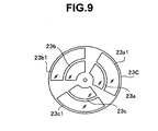
- the first rotational filter section 23C of the light source apparatus 20C has three filters including an Mg filter in an inner circumferential portion and three filters 23a1, 23b1 and 23c1 including a magenta 2 (Mg2) filter in an outer circumferential portion.
- the second rotational filter 24C has a Ye filter 24a for NBI and a yellow 2 (Ye2) filter 24b1 for AFI.
- the rotational filter unit 25C can move along a surface perpendicular to the light path LP and can place the inner circumferential portion or outer circumferential portion of the first rotational filter section 23C in the light path LP according to the observation mode.
- the band selection filter section 22 has three types of filter; for normal light imaging, for narrow band imaging and for auto fluorescence imaging and the filters corresponding to the respective observation modes are placed in the light path LP.
- the Mg filter and the Ye filter or the Mg2 filter and the Ye2 filter are controlled so as to be simultaneously placed in the light path LP.
- the rotational filter unit 25C is then controlled so that the inner circumferential portion is placed in the light path LP in narrow band imaging, and the outer circumferential portion is placed in the light path LP in auto fluorescence imaging.
- Their respective operations or the like in special light imaging are the same as those of the already described endoscope systems 1 to 1B.
- the endoscope system 1C has the effects of the endoscope system 1 and can further perform narrow band imaging and auto fluorescence imaging.
- an endoscope system 1D according to a fourth embodiment will be described. Since the endoscope system 1D of the present embodiment is similar to the endoscope system 1 or the like of the first embodiment, the same components will be assigned the same reference numerals and descriptions thereof will be omitted.
- the endoscope system 1D of the present embodiment can perform narrow band imaging and infrared imaging (IRI) as special light imaging in addition to normal light imaging.
- IRI infrared imaging
- a light source apparatus 20D of the endoscope system 1D includes a band limiting filter 22d which is an IRI filter in the band selection filter section 22.
- the transmittance of the IRI filter is 93% or above only in an IR1 wavelength band of 800 to 830 nm and an IR2 wavelength band of 910 to 950 nm.
- the transmittance of a green (G+IR1) filter 23b2 of the first rotational filter section 23D is 90% or above in 780 to 805 nm which is an IR1 wavelength band in addition to the green wavelength band.
- the transmittance of a blue (B+IR2) filter 23a2 is 90% or above in 920 to 950 nm which is an IR2 wavelength band in addition to the blue wavelength band.
- the IRI filter of the band selection filter section 22 is placed in the light path LP.
- irradiating light in the IR1 wavelength band is supplied when the green (G+IR1) filter 23b2 is placed in the light path LP in the first rotational filter section 23 and irradiating light of the IR2 wavelength band is supplied when the blue (G+IR2) filter 23b2 is placed in the light path LP.
- infrared light is not radiated when the Mg filter 23c is placed in the light path LP in the first rotational filter section 23, but as shown in Fig. 12 , infrared light in the IR1 wavelength band can be radiated by using the Mg2 (Mg+IR1) filter having a transmission region also in the infrared light region.
- Mg2 Mg+IR1
- the IR1 wavelength band in the above description is equivalent to the IR2 wavelength band and the G filter and Mg filter may have a transmission region in the IR2 wavelength band or the B filter may have a transmission region in the IR1 wavelength band. Furthermore, the G filter and the B filter may have a transmission region in the IR1 wavelength band or the Mg filter may have a transmission region in the IR2 wavelength band.
- the endoscope system 1D has the effects of the endoscope system 1 or the like and can further perform narrow band imaging and infrared imaging.
- a cyan filter may also be used according to the target image (irradiating light) or the combination of the primary color filter and the complementary color filter may also be changed according to the target image (irradiating light) as appropriate.
- the Cy filter and the Mg filter that transmit blue light and green light may be combined to supply blue light.
- the falling wavelength of transmittance of the Cy filter and the rising wavelength of the Mg filter are preferably 30 nm or above.
- the Cy filter and the Ye filter may be combined to supply green light.
- the transmittance on the longer wavelength side of the visible light region of the Cy filter and the transmittance of the shorter wavelength side of the visible light region of the Ye filter are preferably 1% or below.
- the light source apparatus and the endoscope system of the present invention are not limited to the above-described special light imaging, but are also applicable to other special light imaging.
- the present invention may also be applicable to an endoscope provided with a light source apparatus for infrared auto fluorescence imaging or photo-dynamic imaging.
- the infrared auto fluorescence imaging is an imaging method using a fluorescent image in an infrared band.
- the photo-dynamic imaging is a method of imaging fluorescence by accumulating a photosensitive substance such as porphyrin derivative in a lesion to be treated and furthermore, a photosensitive substance may be caused to produce active oxygen when transitioning from an excited state to a ground state, interfere with cell respiration and thereby denature and necrose cells.
- the filter characteristics or the like used in the above descriptions are examples of the specification and the filter characteristics are not limited thereto.
- the Mg filter may not necessarily be placed on the inner and outer circumferences, but may be placed on one of the two.
- an endoscope system (light source apparatus) capable of performing normal light imaging, narrow band imaging, infrared imaging and auto fluorescence imaging may be configured by combining the components of the endoscope system 1C (light source apparatus 20C) and the components of the endoscope system 1D (light source apparatus 20D).
Applications Claiming Priority (2)
| Application Number | Priority Date | Filing Date | Title |
|---|---|---|---|
| JP2010085415 | 2010-04-01 | ||
| PCT/JP2011/056537 WO2011125457A1 (ja) | 2010-04-01 | 2011-03-18 | 光源装置および内視鏡システム |
Publications (3)
| Publication Number | Publication Date |
|---|---|
| EP2433552A4 EP2433552A4 (en) | 2012-03-28 |
| EP2433552A1 EP2433552A1 (en) | 2012-03-28 |
| EP2433552B1 true EP2433552B1 (en) | 2013-01-16 |
Family
ID=44762413
Family Applications (1)
| Application Number | Title | Priority Date | Filing Date |
|---|---|---|---|
| EP11765359A Not-in-force EP2433552B1 (en) | 2010-04-01 | 2011-03-18 | Light source apparatus and endoscope system |
Country Status (5)
| Country | Link |
|---|---|
| US (1) | US8419633B2 (ja) |
| EP (1) | EP2433552B1 (ja) |
| JP (1) | JP4884574B2 (ja) |
| CN (1) | CN102469932B (ja) |
| WO (1) | WO2011125457A1 (ja) |
Families Citing this family (32)
| Publication number | Priority date | Publication date | Assignee | Title |
|---|---|---|---|---|
| US9642606B2 (en) | 2012-06-27 | 2017-05-09 | Camplex, Inc. | Surgical visualization system |
| US9216068B2 (en) | 2012-06-27 | 2015-12-22 | Camplex, Inc. | Optics for video cameras on a surgical visualization system |
| KR102127100B1 (ko) | 2012-07-26 | 2020-06-29 | 디퍼이 신테스 프로덕츠, 인코포레이티드 | 광 부족 환경에서 ycbcr 펄싱된 조명 수법 |
| BR112015001555A2 (pt) | 2012-07-26 | 2017-07-04 | Olive Medical Corp | vídeo contínuo em ambiente com deficiência de luz |
| JP5715602B2 (ja) * | 2012-09-07 | 2015-05-07 | 富士フイルム株式会社 | 内視鏡システム及び内視鏡システムの作動方法 |
| CN102920420B (zh) * | 2012-10-11 | 2015-07-29 | 北京大学 | 一种内窥镜装置 |
| JP2014128394A (ja) * | 2012-12-28 | 2014-07-10 | Hoya Corp | 内視鏡装置 |
| US9777913B2 (en) | 2013-03-15 | 2017-10-03 | DePuy Synthes Products, Inc. | Controlling the integral light energy of a laser pulse |
| EP2967301B1 (en) | 2013-03-15 | 2021-11-03 | DePuy Synthes Products, Inc. | Scope sensing in a light controlled environment |
| US9641815B2 (en) | 2013-03-15 | 2017-05-02 | DePuy Synthes Products, Inc. | Super resolution and color motion artifact correction in a pulsed color imaging system |
| WO2014189969A1 (en) | 2013-05-21 | 2014-11-27 | Camplex, Inc. | Surgical visualization systems |
| JP5976045B2 (ja) * | 2013-08-27 | 2016-08-23 | 富士フイルム株式会社 | 内視鏡用光源装置、およびこれを用いた内視鏡システム |
| JP2015047395A (ja) * | 2013-09-03 | 2015-03-16 | Hoya株式会社 | 内視鏡用光源装置および電子内視鏡システム |
| WO2015042483A2 (en) | 2013-09-20 | 2015-03-26 | Camplex, Inc. | Surgical visualization systems |
| JP6521982B2 (ja) | 2013-09-20 | 2019-05-29 | キャンプレックス インコーポレイテッド | 手術可視化システム及びディスプレイ |
| JP5931031B2 (ja) * | 2013-09-23 | 2016-06-08 | 富士フイルム株式会社 | 内視鏡システム及び内視鏡システムの作動方法 |
| CN104083141B (zh) * | 2013-11-21 | 2016-06-29 | 北京华科创智健康科技股份有限公司 | 一种多光谱组合输出光源装置及内窥镜装置 |
| CN106102559A (zh) | 2014-03-21 | 2016-11-09 | 德普伊新特斯产品公司 | 用于成像传感器的卡缘连接器 |
| CN106537906B (zh) * | 2014-07-15 | 2019-03-29 | 夏普株式会社 | 摄像装置和分析装置 |
| WO2016072225A1 (ja) * | 2014-11-07 | 2016-05-12 | オリンパス株式会社 | 撮像システム |
| US10702353B2 (en) | 2014-12-05 | 2020-07-07 | Camplex, Inc. | Surgical visualizations systems and displays |
| WO2016151672A1 (ja) * | 2015-03-20 | 2016-09-29 | オリンパス株式会社 | 生体観察装置 |
| US11154378B2 (en) | 2015-03-25 | 2021-10-26 | Camplex, Inc. | Surgical visualization systems and displays |
| CN107405062B (zh) | 2015-07-02 | 2019-07-05 | 奥林巴斯株式会社 | 驱动装置 |
| JP2017093843A (ja) * | 2015-11-25 | 2017-06-01 | オリンパス株式会社 | 内視鏡システム |
| EP3383247A4 (en) | 2015-11-25 | 2019-06-26 | Camplex, Inc. | SURGICAL VISUALIZATION SYSTEMS AND DISPLAYS |
| KR102011488B1 (ko) * | 2016-09-07 | 2019-08-16 | 한국전자통신연구원 | 열분포 모니터링을 위한 내시경 장치 |
| US10918455B2 (en) | 2017-05-08 | 2021-02-16 | Camplex, Inc. | Variable light source |
| JP7123135B2 (ja) * | 2018-06-19 | 2022-08-22 | オリンパス株式会社 | 内視鏡装置、内視鏡装置の作動方法及びプログラム |
| DE102019123053A1 (de) * | 2019-08-28 | 2021-03-04 | Olympus Winter & Ibe Gmbh | Endoskop mit optischer Filteranordnung und Verwendung |
| DE102020100676B3 (de) * | 2020-01-14 | 2021-04-01 | Karl Storz Se & Co. Kg | Filterwechselvorrichtung für ein optisches Beobachtungsinstrument mit zwei Strahlengängen, optisches Beobachtungsinstrument und Verfahren zum Wechseln eines Filters eines optischen Beobachtungsinstruments |
| CN117642695A (zh) * | 2021-07-29 | 2024-03-01 | 富士胶片株式会社 | 透镜装置、摄像装置及滤光器单元 |
Family Cites Families (16)
| Publication number | Priority date | Publication date | Assignee | Title |
|---|---|---|---|---|
| US4983019A (en) * | 1987-05-06 | 1991-01-08 | Olympus Optical Co., Ltd. | Endoscope light source apparatus |
| JP2666856B2 (ja) * | 1988-10-15 | 1997-10-22 | オリンパス光学工業株式会社 | 内視鏡用光源装置 |
| EP2319390B1 (en) * | 2000-07-21 | 2016-04-20 | Olympus Corporation | Endoscope apparatus |
| JP3579638B2 (ja) * | 2000-08-08 | 2004-10-20 | ペンタックス株式会社 | 内視鏡装置 |
| DE60228165D1 (de) * | 2001-05-16 | 2008-09-25 | Olympus Corp | Endoskop mit Bildverarbeitungseinrichtung |
| US7172553B2 (en) * | 2001-05-16 | 2007-02-06 | Olympus Corporation | Endoscope system using normal light and fluorescence |
| JP4147033B2 (ja) * | 2002-01-18 | 2008-09-10 | オリンパス株式会社 | 内視鏡装置 |
| JP2003334162A (ja) * | 2002-03-14 | 2003-11-25 | Olympus Optical Co Ltd | 内視鏡画像処理装置 |
| JP4294440B2 (ja) * | 2003-10-30 | 2009-07-15 | オリンパス株式会社 | 画像処理装置 |
| FR2866443A1 (fr) * | 2004-02-12 | 2005-08-19 | Thomson Licensing Sa | Systeme d'illumination sequentiel couleur, procede de realisation d'une roue coloree pour le systeme et dispositif de segments colores |
| JP2006271871A (ja) * | 2005-03-30 | 2006-10-12 | Olympus Medical Systems Corp | 内視鏡用画像処理装置 |
| JP4855728B2 (ja) * | 2005-07-27 | 2012-01-18 | オリンパスメディカルシステムズ株式会社 | 照明装置及び観察装置 |
| JP4744288B2 (ja) * | 2005-12-21 | 2011-08-10 | オリンパスメディカルシステムズ株式会社 | 内視鏡装置 |
| JP4959469B2 (ja) * | 2007-08-22 | 2012-06-20 | オリンパスメディカルシステムズ株式会社 | 光源装置 |
| JP5226403B2 (ja) * | 2008-07-04 | 2013-07-03 | オリンパスメディカルシステムズ株式会社 | 光源装置及びこの光源装置を用いた内視鏡装置 |
| JP2010085415A (ja) | 2009-12-28 | 2010-04-15 | Japan Atomic Energy Agency | 2次元放射線および中性子イメージ検出器 |
-
2011
- 2011-03-18 CN CN2011800029767A patent/CN102469932B/zh active Active
- 2011-03-18 JP JP2011540252A patent/JP4884574B2/ja active Active
- 2011-03-18 WO PCT/JP2011/056537 patent/WO2011125457A1/ja active Application Filing
- 2011-03-18 EP EP11765359A patent/EP2433552B1/en not_active Not-in-force
- 2011-09-27 US US13/246,214 patent/US8419633B2/en active Active
Also Published As
| Publication number | Publication date |
|---|---|
| CN102469932A (zh) | 2012-05-23 |
| JPWO2011125457A1 (ja) | 2013-07-08 |
| EP2433552A4 (en) | 2012-03-28 |
| CN102469932B (zh) | 2013-04-24 |
| US8419633B2 (en) | 2013-04-16 |
| JP4884574B2 (ja) | 2012-02-29 |
| US20120130175A1 (en) | 2012-05-24 |
| EP2433552A1 (en) | 2012-03-28 |
| WO2011125457A1 (ja) | 2011-10-13 |
Similar Documents
| Publication | Publication Date | Title |
|---|---|---|
| EP2433552B1 (en) | Light source apparatus and endoscope system | |
| US9277190B2 (en) | Endoscope apparatus | |
| EP2020202B9 (en) | Medical apparatus | |
| JP4734074B2 (ja) | 内視鏡装置 | |
| JP3869324B2 (ja) | 蛍光観察用画像処理装置 | |
| JP6005303B2 (ja) | 蛍光観察内視鏡システム | |
| US8723940B2 (en) | Endoscope apparatus | |
| JP4855728B2 (ja) | 照明装置及び観察装置 | |
| US8107158B2 (en) | Fluorescent imaging device and fluorescent image acquiring method | |
| JP6827512B2 (ja) | 内視鏡システム | |
| WO2013145410A1 (ja) | 内視鏡装置 | |
| JP5976045B2 (ja) | 内視鏡用光源装置、およびこれを用いた内視鏡システム | |
| US20130006109A1 (en) | Endoscope apparatus | |
| JP2009000236A (ja) | 画像生成装置 | |
| JP5467971B2 (ja) | 電子内視鏡システム、電子内視鏡システムのプロセッサ装置及び電子内視鏡システムの作動方法 | |
| JP5539841B2 (ja) | 電子内視鏡システム、電子内視鏡システムのプロセッサ装置、及び電子内視鏡システムの作動方法 | |
| JP2012081048A (ja) | 電子内視鏡システム、電子内視鏡、及び励起光照射方法 | |
| JP2012045266A (ja) | 電子内視鏡システム、電子内視鏡システムのプロセッサ装置及び電子内視鏡システムにおける撮像制御方法 |
Legal Events
| Date | Code | Title | Description |
|---|---|---|---|
| PUAI | Public reference made under article 153(3) epc to a published international application that has entered the european phase |
Free format text: ORIGINAL CODE: 0009012 |
|
| 17P | Request for examination filed |
Effective date: 20111220 |
|
| A4 | Supplementary search report drawn up and despatched |
Effective date: 20120207 |
|
| AK | Designated contracting states |
Kind code of ref document: A1 Designated state(s): AL AT BE BG CH CY CZ DE DK EE ES FI FR GB GR HR HU IE IS IT LI LT LU LV MC MK MT NL NO PL PT RO RS SE SI SK SM TR |
|
| GRAP | Despatch of communication of intention to grant a patent |
Free format text: ORIGINAL CODE: EPIDOSNIGR1 |
|
| GRAS | Grant fee paid |
Free format text: ORIGINAL CODE: EPIDOSNIGR3 |
|
| GRAA | (expected) grant |
Free format text: ORIGINAL CODE: 0009210 |
|
| AK | Designated contracting states |
Kind code of ref document: B1 Designated state(s): AL AT BE BG CH CY CZ DE DK EE ES FI FR GB GR HR HU IE IS IT LI LT LU LV MC MK MT NL NO PL PT RO RS SE SI SK SM TR |
|
| DAX | Request for extension of the european patent (deleted) | ||
| REG | Reference to a national code |
Ref country code: GB Ref legal event code: FG4D |
|
| REG | Reference to a national code |
Ref country code: CH Ref legal event code: EP |
|
| REG | Reference to a national code |
Ref country code: IE Ref legal event code: FG4D |
|
| REG | Reference to a national code |
Ref country code: AT Ref legal event code: REF Ref document number: 593413 Country of ref document: AT Kind code of ref document: T Effective date: 20130215 Ref country code: CH Ref legal event code: EP |
|
| REG | Reference to a national code |
Ref country code: DE Ref legal event code: R096 Ref document number: 602011000804 Country of ref document: DE Effective date: 20130321 |
|
| REG | Reference to a national code |
Ref country code: AT Ref legal event code: MK05 Ref document number: 593413 Country of ref document: AT Kind code of ref document: T Effective date: 20130116 |
|
| REG | Reference to a national code |
Ref country code: NL Ref legal event code: VDEP Effective date: 20130116 |
|
| REG | Reference to a national code |
Ref country code: LT Ref legal event code: MG4D |
|
| PG25 | Lapsed in a contracting state [announced via postgrant information from national office to epo] |
Ref country code: BG Free format text: LAPSE BECAUSE OF FAILURE TO SUBMIT A TRANSLATION OF THE DESCRIPTION OR TO PAY THE FEE WITHIN THE PRESCRIBED TIME-LIMIT Effective date: 20130416 Ref country code: AT Free format text: LAPSE BECAUSE OF FAILURE TO SUBMIT A TRANSLATION OF THE DESCRIPTION OR TO PAY THE FEE WITHIN THE PRESCRIBED TIME-LIMIT Effective date: 20130116 Ref country code: IS Free format text: LAPSE BECAUSE OF FAILURE TO SUBMIT A TRANSLATION OF THE DESCRIPTION OR TO PAY THE FEE WITHIN THE PRESCRIBED TIME-LIMIT Effective date: 20130516 Ref country code: BE Free format text: LAPSE BECAUSE OF FAILURE TO SUBMIT A TRANSLATION OF THE DESCRIPTION OR TO PAY THE FEE WITHIN THE PRESCRIBED TIME-LIMIT Effective date: 20130116 Ref country code: SE Free format text: LAPSE BECAUSE OF FAILURE TO SUBMIT A TRANSLATION OF THE DESCRIPTION OR TO PAY THE FEE WITHIN THE PRESCRIBED TIME-LIMIT Effective date: 20130116 Ref country code: ES Free format text: LAPSE BECAUSE OF FAILURE TO SUBMIT A TRANSLATION OF THE DESCRIPTION OR TO PAY THE FEE WITHIN THE PRESCRIBED TIME-LIMIT Effective date: 20130427 Ref country code: NO Free format text: LAPSE BECAUSE OF FAILURE TO SUBMIT A TRANSLATION OF THE DESCRIPTION OR TO PAY THE FEE WITHIN THE PRESCRIBED TIME-LIMIT Effective date: 20130416 Ref country code: LT Free format text: LAPSE BECAUSE OF FAILURE TO SUBMIT A TRANSLATION OF THE DESCRIPTION OR TO PAY THE FEE WITHIN THE PRESCRIBED TIME-LIMIT Effective date: 20130116 |
|
| PG25 | Lapsed in a contracting state [announced via postgrant information from national office to epo] |
Ref country code: FI Free format text: LAPSE BECAUSE OF FAILURE TO SUBMIT A TRANSLATION OF THE DESCRIPTION OR TO PAY THE FEE WITHIN THE PRESCRIBED TIME-LIMIT Effective date: 20130116 Ref country code: LV Free format text: LAPSE BECAUSE OF FAILURE TO SUBMIT A TRANSLATION OF THE DESCRIPTION OR TO PAY THE FEE WITHIN THE PRESCRIBED TIME-LIMIT Effective date: 20130116 Ref country code: PT Free format text: LAPSE BECAUSE OF FAILURE TO SUBMIT A TRANSLATION OF THE DESCRIPTION OR TO PAY THE FEE WITHIN THE PRESCRIBED TIME-LIMIT Effective date: 20130516 Ref country code: GR Free format text: LAPSE BECAUSE OF FAILURE TO SUBMIT A TRANSLATION OF THE DESCRIPTION OR TO PAY THE FEE WITHIN THE PRESCRIBED TIME-LIMIT Effective date: 20130417 Ref country code: PL Free format text: LAPSE BECAUSE OF FAILURE TO SUBMIT A TRANSLATION OF THE DESCRIPTION OR TO PAY THE FEE WITHIN THE PRESCRIBED TIME-LIMIT Effective date: 20130116 Ref country code: NL Free format text: LAPSE BECAUSE OF FAILURE TO SUBMIT A TRANSLATION OF THE DESCRIPTION OR TO PAY THE FEE WITHIN THE PRESCRIBED TIME-LIMIT Effective date: 20130116 Ref country code: SI Free format text: LAPSE BECAUSE OF FAILURE TO SUBMIT A TRANSLATION OF THE DESCRIPTION OR TO PAY THE FEE WITHIN THE PRESCRIBED TIME-LIMIT Effective date: 20130116 |
|
| PG25 | Lapsed in a contracting state [announced via postgrant information from national office to epo] |
Ref country code: HR Free format text: LAPSE BECAUSE OF FAILURE TO SUBMIT A TRANSLATION OF THE DESCRIPTION OR TO PAY THE FEE WITHIN THE PRESCRIBED TIME-LIMIT Effective date: 20130116 Ref country code: RS Free format text: LAPSE BECAUSE OF FAILURE TO SUBMIT A TRANSLATION OF THE DESCRIPTION OR TO PAY THE FEE WITHIN THE PRESCRIBED TIME-LIMIT Effective date: 20130116 |
|
| PG25 | Lapsed in a contracting state [announced via postgrant information from national office to epo] |
Ref country code: EE Free format text: LAPSE BECAUSE OF FAILURE TO SUBMIT A TRANSLATION OF THE DESCRIPTION OR TO PAY THE FEE WITHIN THE PRESCRIBED TIME-LIMIT Effective date: 20130116 Ref country code: MC Free format text: LAPSE BECAUSE OF NON-PAYMENT OF DUE FEES Effective date: 20130331 Ref country code: DK Free format text: LAPSE BECAUSE OF FAILURE TO SUBMIT A TRANSLATION OF THE DESCRIPTION OR TO PAY THE FEE WITHIN THE PRESCRIBED TIME-LIMIT Effective date: 20130116 Ref country code: SK Free format text: LAPSE BECAUSE OF FAILURE TO SUBMIT A TRANSLATION OF THE DESCRIPTION OR TO PAY THE FEE WITHIN THE PRESCRIBED TIME-LIMIT Effective date: 20130116 Ref country code: RO Free format text: LAPSE BECAUSE OF FAILURE TO SUBMIT A TRANSLATION OF THE DESCRIPTION OR TO PAY THE FEE WITHIN THE PRESCRIBED TIME-LIMIT Effective date: 20130116 Ref country code: CZ Free format text: LAPSE BECAUSE OF FAILURE TO SUBMIT A TRANSLATION OF THE DESCRIPTION OR TO PAY THE FEE WITHIN THE PRESCRIBED TIME-LIMIT Effective date: 20130116 |
|
| PLBE | No opposition filed within time limit |
Free format text: ORIGINAL CODE: 0009261 |
|
| STAA | Information on the status of an ep patent application or granted ep patent |
Free format text: STATUS: NO OPPOSITION FILED WITHIN TIME LIMIT |
|
| PG25 | Lapsed in a contracting state [announced via postgrant information from national office to epo] |
Ref country code: CY Free format text: LAPSE BECAUSE OF FAILURE TO SUBMIT A TRANSLATION OF THE DESCRIPTION OR TO PAY THE FEE WITHIN THE PRESCRIBED TIME-LIMIT Effective date: 20130116 |
|
| 26N | No opposition filed |
Effective date: 20131017 |
|
| REG | Reference to a national code |
Ref country code: FR Ref legal event code: ST Effective date: 20131129 |
|
| PG25 | Lapsed in a contracting state [announced via postgrant information from national office to epo] |
Ref country code: IT Free format text: LAPSE BECAUSE OF FAILURE TO SUBMIT A TRANSLATION OF THE DESCRIPTION OR TO PAY THE FEE WITHIN THE PRESCRIBED TIME-LIMIT Effective date: 20130116 |
|
| REG | Reference to a national code |
Ref country code: IE Ref legal event code: MM4A |
|
| PG25 | Lapsed in a contracting state [announced via postgrant information from national office to epo] |
Ref country code: IE Free format text: LAPSE BECAUSE OF NON-PAYMENT OF DUE FEES Effective date: 20130318 Ref country code: AL Free format text: LAPSE BECAUSE OF FAILURE TO SUBMIT A TRANSLATION OF THE DESCRIPTION OR TO PAY THE FEE WITHIN THE PRESCRIBED TIME-LIMIT Effective date: 20130116 Ref country code: FR Free format text: LAPSE BECAUSE OF NON-PAYMENT OF DUE FEES Effective date: 20130402 |
|
| REG | Reference to a national code |
Ref country code: DE Ref legal event code: R097 Ref document number: 602011000804 Country of ref document: DE Effective date: 20131017 |
|
| PG25 | Lapsed in a contracting state [announced via postgrant information from national office to epo] |
Ref country code: MT Free format text: LAPSE BECAUSE OF FAILURE TO SUBMIT A TRANSLATION OF THE DESCRIPTION OR TO PAY THE FEE WITHIN THE PRESCRIBED TIME-LIMIT Effective date: 20130116 |
|
| REG | Reference to a national code |
Ref country code: CH Ref legal event code: PL |
|
| PG25 | Lapsed in a contracting state [announced via postgrant information from national office to epo] |
Ref country code: CH Free format text: LAPSE BECAUSE OF NON-PAYMENT OF DUE FEES Effective date: 20140331 Ref country code: LI Free format text: LAPSE BECAUSE OF NON-PAYMENT OF DUE FEES Effective date: 20140331 |
|
| PG25 | Lapsed in a contracting state [announced via postgrant information from national office to epo] |
Ref country code: SM Free format text: LAPSE BECAUSE OF FAILURE TO SUBMIT A TRANSLATION OF THE DESCRIPTION OR TO PAY THE FEE WITHIN THE PRESCRIBED TIME-LIMIT Effective date: 20130116 |
|
| PG25 | Lapsed in a contracting state [announced via postgrant information from national office to epo] |
Ref country code: TR Free format text: LAPSE BECAUSE OF FAILURE TO SUBMIT A TRANSLATION OF THE DESCRIPTION OR TO PAY THE FEE WITHIN THE PRESCRIBED TIME-LIMIT Effective date: 20130116 |
|
| PG25 | Lapsed in a contracting state [announced via postgrant information from national office to epo] |
Ref country code: MK Free format text: LAPSE BECAUSE OF FAILURE TO SUBMIT A TRANSLATION OF THE DESCRIPTION OR TO PAY THE FEE WITHIN THE PRESCRIBED TIME-LIMIT Effective date: 20130116 Ref country code: LU Free format text: LAPSE BECAUSE OF NON-PAYMENT OF DUE FEES Effective date: 20130318 Ref country code: HU Free format text: LAPSE BECAUSE OF FAILURE TO SUBMIT A TRANSLATION OF THE DESCRIPTION OR TO PAY THE FEE WITHIN THE PRESCRIBED TIME-LIMIT; INVALID AB INITIO Effective date: 20110318 |
|
| REG | Reference to a national code |
Ref country code: DE Ref legal event code: R082 Ref document number: 602011000804 Country of ref document: DE Representative=s name: WUESTHOFF & WUESTHOFF, PATENTANWAELTE PARTG MB, DE Ref country code: DE Ref legal event code: R081 Ref document number: 602011000804 Country of ref document: DE Owner name: OLYMPUS CORPORATION, JP Free format text: FORMER OWNER: OLYMPUS MEDICAL SYSTEMS CORP., TOKYO, JP |
|
| GBPC | Gb: european patent ceased through non-payment of renewal fee |
Effective date: 20150318 |
|
| PG25 | Lapsed in a contracting state [announced via postgrant information from national office to epo] |
Ref country code: GB Free format text: LAPSE BECAUSE OF NON-PAYMENT OF DUE FEES Effective date: 20150318 |
|
| PGFP | Annual fee paid to national office [announced via postgrant information from national office to epo] |
Ref country code: DE Payment date: 20190321 Year of fee payment: 9 |
|
| REG | Reference to a national code |
Ref country code: DE Ref legal event code: R119 Ref document number: 602011000804 Country of ref document: DE |
|
| PG25 | Lapsed in a contracting state [announced via postgrant information from national office to epo] |
Ref country code: DE Free format text: LAPSE BECAUSE OF NON-PAYMENT OF DUE FEES Effective date: 20201001 |