EP2433488A2 - Device for automatically pass around posts for tying berry hedges, and corresponding agricultural machines - Google Patents
Device for automatically pass around posts for tying berry hedges, and corresponding agricultural machines Download PDFInfo
- Publication number
- EP2433488A2 EP2433488A2 EP11358009A EP11358009A EP2433488A2 EP 2433488 A2 EP2433488 A2 EP 2433488A2 EP 11358009 A EP11358009 A EP 11358009A EP 11358009 A EP11358009 A EP 11358009A EP 2433488 A2 EP2433488 A2 EP 2433488A2
- Authority
- EP
- European Patent Office
- Prior art keywords
- stakes
- bypassing
- cutting
- stacks
- stack
- Prior art date
- Legal status (The legal status is an assumption and is not a legal conclusion. Google has not performed a legal analysis and makes no representation as to the accuracy of the status listed.)
- Granted
Links
- 235000021028 berry Nutrition 0.000 title 1
- 239000003638 chemical reducing agent Substances 0.000 claims abstract description 13
- 235000013399 edible fruits Nutrition 0.000 claims description 22
- 238000013138 pruning Methods 0.000 claims description 13
- 230000002093 peripheral effect Effects 0.000 claims description 5
- 239000002023 wood Substances 0.000 description 5
- 229910000831 Steel Inorganic materials 0.000 description 3
- 239000010959 steel Substances 0.000 description 3
- XEEYBQQBJWHFJM-UHFFFAOYSA-N Iron Chemical compound [Fe] XEEYBQQBJWHFJM-UHFFFAOYSA-N 0.000 description 2
- 238000013459 approach Methods 0.000 description 2
- 238000004140 cleaning Methods 0.000 description 2
- -1 ..) Substances 0.000 description 1
- 229910000838 Al alloy Inorganic materials 0.000 description 1
- 241000219504 Caryophyllales Species 0.000 description 1
- 230000005540 biological transmission Effects 0.000 description 1
- 230000000295 complement effect Effects 0.000 description 1
- 239000002131 composite material Substances 0.000 description 1
- 230000008878 coupling Effects 0.000 description 1
- 238000010168 coupling process Methods 0.000 description 1
- 238000005859 coupling reaction Methods 0.000 description 1
- 230000001066 destructive effect Effects 0.000 description 1
- 230000006866 deterioration Effects 0.000 description 1
- 238000006073 displacement reaction Methods 0.000 description 1
- 235000021183 entrée Nutrition 0.000 description 1
- 229910052742 iron Inorganic materials 0.000 description 1
- 239000000463 material Substances 0.000 description 1
- 229910052751 metal Inorganic materials 0.000 description 1
- 239000002184 metal Substances 0.000 description 1
- 210000000056 organ Anatomy 0.000 description 1
- 230000035939 shock Effects 0.000 description 1
- 241000894007 species Species 0.000 description 1
- 229910052725 zinc Inorganic materials 0.000 description 1
- 239000011701 zinc Substances 0.000 description 1
Images


Classifications
-
- A—HUMAN NECESSITIES
- A01—AGRICULTURE; FORESTRY; ANIMAL HUSBANDRY; HUNTING; TRAPPING; FISHING
- A01G—HORTICULTURE; CULTIVATION OF VEGETABLES, FLOWERS, RICE, FRUIT, VINES, HOPS OR SEAWEED; FORESTRY; WATERING
- A01G3/00—Cutting implements specially adapted for horticultural purposes; Delimbing standing trees
- A01G3/04—Apparatus for trimming hedges, e.g. hedge shears
- A01G3/0408—Apparatus for trimming hedges, e.g. hedge shears specially adapted for trellis work, e.g. machines for pruning vine or the like
Definitions
- the present invention relates to an automatic bypass device towing stakes or guardians of fruit hedges. It is also aimed at agricultural machinery equipped with such a device.
- the invention relates to a device for automatically bypassing the stakes for agricultural machines comprising a working head shaped to be able to ride a fruit hedge cultivated on stake stakes or on a trellis, such as a row of vines, this trellising being constituted by at least one or, generally, by a plurality of support wires superimposed and spaced supported, from place to place, by stakes executed in a rigid and resistant material such as wood, metal (galvanized iron, steel, aluminum alloy -zinc, ..), concrete, composite materials, etc.
- this automatic opening is obtained by the conformation of the cutting tools stacked around the vertical drive shafts.
- These cutting tools comprise a rotary circular cage provided, peripherally, notches separated by teeth and in which are fixedly fixed cutting blades, said cage and said blades being arranged in a complementary manner and associated to form a blade system and counterblade producing a shear cut.
- the rotating cages of the stacks of cutting tools are rotated at a tangential speed substantially equal to the linear speed of advance of the carrier machine on which is mounted the working head of the machine, so that when the stacks close-up tools meet a trellis peg, the latter does not suffer any shock because of the fact that said stacks roll on the stake without damaging it and without risk of damage to the cutting tools.
- the cutting system of these machines comprises two stacks of crumbling members consisting of steel discs indented at the periphery to form alternating teeth and troughs.
- the peripheral teeth of the cutting discs can be sharpened.
- the tools or cutting discs thus produced are stacked on two vertical shafts at a regular distance from each other of the order of a few centimeters, for example 10 cm.
- the two vertical shafts are placed on either side of the trellis axis and are adjusted so that the right stacking disks and the left stacking disks intersect a few centimeters, for example 5 cm, in the horizontal plane, in the close position of work, and are arranged a few millimeters from each other, 10 mm for example in the vertical plane.
- the speed at the periphery of the rotating cutting discs must be twice the speed of movement of the machine, so as to facilitate the cutting of wood and to have a good cleaning of the trellis son.
- This rotational speed of the discs can be adjusted by means of a flow divider equipping the hydraulic system for rotating said cutting discs.
- the two stacks of toothed cutting discs being held in pressure against the fruit hedge, so as not to be separated from each other under the cutting force of the vegetation, they must be discarded at the passage of each stake of the trellis by the operator; the discs rotating at a peripheral speed greater than the speed of advance of the machine, if the operator does not spread the stacks, the stakes could be damaged when they are wooden or cause deterioration of the discs when said stakes are steel or concrete.
- the stacks of cutting discs are spaced apart so as not to cut the abutment son.
- Trellis wires must be properly tensioned so as not to be caught or severed while moving the machine in the row.
- opening wheels have a diameter slightly greater than the diameter of the toothed cutting discs, for example a diameter 2 cm greater than the diameter of the cutting discs, so that during the passage of the cutting stacks on the stakes of the trellising, these the last are in contact with the opening wheels only and not cutting discs.
- peripheral speed of the opening wheels being greater than the forward speed of the machine to avoid bad cutting of the wood
- main disadvantage of such a system is to pull the stakes backwards, and possibly, the twist or break them when coming into contact with them.
- the opening wheels are mounted via a bearing, so as to be crazy. In this case, these opening wheels are not rotated, the main disadvantage of such an arrangement is to push the stakes forward, and possibly to twist or break, during the meeting said stakes.
- Another known possibility is to mount the opening wheels by means of a bearing on the drive shafts and to drive them in rotation by a motor unit external to the stacks, of the type, for example, belt or chain. transmission; the main disadvantages of such a system are its complexity, its size and its relatively high cost.
- An object of the present invention is to overcome the aforementioned drawbacks of pre-pruning machines of the type comprising a working head comprising two vertical drive shafts on which are mounted two stacks of toothed cutting disks and an opening wheel.
- this objective is achieved by mounting this rotating opening wheel on the vertical drive shaft of each stack of toothed cutting discs, by means of a speed reducer coupled to said shaft.
- the speed ratio between the rotation of the drive shafts of the toothed cutting discs and the rotation of the opening wheels is 1/2, so that if the cutting discs rotate, for example, at 200 rpm, the opening wheels, they turn at 100 r / min.
- the speed reducers consist of planetary reduction gears.
- one of the faces of the opening wheel of each stack of toothed discs is arranged to form a counter-blade mounted opposite one of the toothed cutting disks of the opposite stack of disks.
- This provides a collaborative work between the opening wheel and the disk of the opposite stack so that the trellising can be pre-pruned over the entire height of the stacks.
- fruit hedge refers to a row or alignment of fruiting shrubs which may be of various species grown on a trellis or on stakes, such as rows of vines.
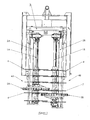
- the cutting head of the pre-pruning machine illustrated in figure 1 has two vertical rotating drive shafts 1A, 1B. Each of these shafts is supported by a vertical pivoting cradle 2A, 2B, and rotated by a motor which can be constituted by a hydraulic motor coupled to the upper end of said drive shafts.
- This pivoting vertical cradle is itself suspended, in a pendular manner and known per se, to a support arm hingedly connected to the frame 3 of the cutting head.
- each of the vertical drive shafts 1A, 1B are mounted toothed cutting discs or circular saws 4, stacked on said shafts, remotely, preferably regularly, from each other.
- the stacks 4A, 4B are offset in the vertical direction, so that the toothed cutting discs interpenetrate in a position close to said stacks or closing position of the cutting head. More specifically, the toothed cutting discs of the right stack 4A and the toothed cutting discs of the left stack 4B intersect, in the horizontal plane, over a distance of a few centimeters, for example over a distance of the order 5 cm.
- At least one rotary opening wheel 5A, 5B is mounted around each vertical shaft 1A, 1B, these opening wheels being rotated by said shafts.
- each opening wheel is mounted on its drive shaft 1A, 1B, via a speed reducer coupled in rotation to said shaft.
- these speed reducers consist of planetary reduction gears.
- the satellites 16 are engaged: - on the one hand, with the toothing of the sun gear 6 and, on the other hand, with the toothing of the sun gear 9 constituted by a circular ring toothed internally.
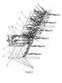
- the satellite door 15 of the opening wheels 5A, 5B which has a diameter greater than the diameter of the toothed cutting disks 4, bears and is wound on the stakes P1 of the trellis P, as the machine moves forward. pre-pruning on the fruit hedge H with a rotation speed V2 which has been previously adjusted by the user to correspond substantially to the forward speed of the machine so as not to exert any pushing or pulling force on said pegs.
- the opening wheels 5A and 5B proper are constituted by the periphery of the rotary satellite carrier 15.
- the cutting stacks 4A, 4B rotate at a rotational speed V1 two times greater than the rotation speed V2 of the opening wheels and allow preassembly and crumbling of the woods or vines of excellent quality, as well as a good cleaning the trellis wires of the fruit hedge.
- the cutting discs rotate at 200 rpm, while the opening wheels rotate at 100 rpm.
- a circular against-blade 18 is fixed, by means of screws 19, on the satellite door 15 of each opening wheel.
- the counterblade 18 is provided, peripherally and alternately, with teeth 21 and notches 22.
- the counterblade is disposed on the upper face of the epicyclic gearbox formed by the planet carrier 15 and is placed opposite the lower face of the disk 4 of the stack opposite to which it is associated.
Landscapes
- Life Sciences & Earth Sciences (AREA)
- Biodiversity & Conservation Biology (AREA)
- Ecology (AREA)
- Forests & Forestry (AREA)
- Environmental Sciences (AREA)
- Harvester Elements (AREA)
- Harvesting Machines For Specific Crops (AREA)
- Scissors And Nippers (AREA)
- Retarders (AREA)
- Preparation Of Fruits And Vegetables (AREA)
Abstract
Description
La présente invention concerne un dispositif de contournement automatique des piquets de palissage ou des tuteurs de haies fruitières. Elle vise également les machines agricoles équipées d'un tel dispositif.The present invention relates to an automatic bypass device towing stakes or guardians of fruit hedges. It is also aimed at agricultural machinery equipped with such a device.
Plus précisément, l'invention concerne un dispositif de contournement automatique des piquets pour machines agricoles comportant une tête de travail conformée pour pouvoir chevaucher une haie fruitière cultivée sur des piquets de tuteurage ou sur un palissage, telle qu'un rang de ceps de vignes, ce palissage étant constitué par au moins un ou, généralement, par plusieurs fils de soutien superposés et espacés soutenus, de place en place, par des piquets exécutés dans un matériau rigide et résistant tel que bois, métal (fer galvanisé, acier, alliage aluminium-zinc, ..), béton, matériaux composites, etc.More specifically, the invention relates to a device for automatically bypassing the stakes for agricultural machines comprising a working head shaped to be able to ride a fruit hedge cultivated on stake stakes or on a trellis, such as a row of vines, this trellising being constituted by at least one or, generally, by a plurality of support wires superimposed and spaced supported, from place to place, by stakes executed in a rigid and resistant material such as wood, metal (galvanized iron, steel, aluminum alloy -zinc, ..), concrete, composite materials, etc.
Elle s'applique plus particulièrement aux machines de taille ou de prétaillage des haies fruitières.It is particularly applicable to pruning or pruning machines for fruit hedges.
On décrit donc plus spécialement ci-après cette application très intéressante du dispositif de l'invention aux machines agencées et utilisées pour le prétaillage de la vigne, mais on souligne que la référence à une machine de prétaillage, dans la suite du présent exposé, ne saurait avoir un caractère limitatif.This particularly interesting application of the device of the invention to the machines arranged and used for pre-pruning the vine is therefore more particularly described below, but it is pointed out that the reference to a pre-pruning machine, in the remainder of the present description, does not can not be limiting.
On rappelle que l'objectif du prétaillage mécanique de la vigne est de simplifier le travail ultérieur du tailleur en éliminant le maximum de bois avant la taille manuelle.It should be remembered that the purpose of the mechanical pre-pruning of the vine is to simplify the tailor's subsequent work by eliminating the maximum amount of wood before manual cutting.
Lors de cette opération préparatoire, les bois ou sarments dont les vrilles sont fixées aux fils de palissage sont sectionnés et dégagés. La grosse difficulté de ce travail consiste à assurer le passage des piquets qui constituent des obstacles à l'avancement des organes de coupe de la tête de travail de la machine, la contrainte étant que l'action de cette dernière ne doit pas être destructrice vis-à-vis des piquets et des fils de palissage ou de ses propres organes de coupe.During this preparatory operation, the wood or branches whose tendrils are attached to the trellis son are sectioned and released. The great difficulty of this work is to ensure the passage of the stakes which are obstacles to the advancement of the cutting members of the working head of the machine, the constraint being that the action of the latter should not be destructive to pegs and trellis wires or its own cutters.
La plupart des machines de prétaillage actuelles utilisent des systèmes de coupe rotatifs.Most current pre-cutting machines use rotary cutting systems.
La tête de travail de ces machines comprend deux empilements d'organes de coupe rotatifs montés, de manière espacée, sur des arbres d'entraînement verticaux, ces empilements décalés en direction verticale pouvant occuper deux positions, soit :
- une position rapprochée de travail, ou position de fermeture, selon laquelle les bords des organes de coupe rotatifs des deux empilements s'interpénètrent ;
- une position d'ouverture permettant le contournement des piquets du palissage, suivant laquelle les empilements d'outils rotatifs se trouvent séparés par un espace vertical.
- a close working position, or closing position, in which the edges of the rotary cutting members of the two stacks interpenetrate;
- an opening position for circumventing the stakes of the trellis, according to which the stacks of rotary tools are separated by a vertical space.
Plusieurs dispositifs ont été proposés pour obtenir l'ouverture automatique de la tête de travail au passage des piquets.Several devices have been proposed to obtain the automatic opening of the working head to the passage of the pegs.
Selon le document
Les cages tournantes des empilements d'outils de coupe sont entraînées en rotation à une vitesse tangentielle sensiblement égale à la vitesse linéaire d'avancement de l'engin porteur sur lequel est montée la tête de travail de la machine, de sorte que lorsque les empilements d'outils rapprochés rencontrent un piquet de palissage, ce dernier ne subit aucun choc en raison du fait que lesdits empilements roulent sur le piquet sans l'endommager et sans risque de détérioration des outils de coupe.The rotating cages of the stacks of cutting tools are rotated at a tangential speed substantially equal to the linear speed of advance of the carrier machine on which is mounted the working head of the machine, so that when the stacks close-up tools meet a trellis peg, the latter does not suffer any shock because of the fact that said stacks roll on the stake without damaging it and without risk of damage to the cutting tools.
Les autres résultats particulièrement avantageux obtenus grâce à la machine de prétaillage décrite dans le document
C'est pourquoi il a été proposé de réduire ce coût en remplaçant l'un des empilements des outils de coupe de la tête de travail par un empilement de disques ameneurs (voir par exemple
On trouve donc, sur le marché, des prétailleuses comportant une tête de travail ou tête de coupe constituée d'outils de coupe plus rustiques, permettant de les proposer à des prix de revient plus attractifs répondant au souhait de certains utilisateurs. Le système de coupe de ces machines comprend deux empilements d'organes d'émiettage constitués de disques d'acier échancrés en périphérie pour former des dents et des creux alternés.There are therefore on the market, pre-pruners with a working head or cutting head made of more rustic cutting tools, to offer them at more attractive cost prices meeting the wishes of certain users. The cutting system of these machines comprises two stacks of crumbling members consisting of steel discs indented at the periphery to form alternating teeth and troughs.
Pour améliorer la qualité de coupe des bois, les dents périphériques des disques de coupe peuvent être affûtées. Les outils ou disques de coupe ainsi réalisés sont empilés sur deux arbres verticaux à une distance régulière les uns des autres de l'ordre de quelques centimètres, 10 cm par exemple.To improve the cutting quality of the woods, the peripheral teeth of the cutting discs can be sharpened. The tools or cutting discs thus produced are stacked on two vertical shafts at a regular distance from each other of the order of a few centimeters, for example 10 cm.
Les deux arbres verticaux se placent de part et d'autre de l'axe du palissage et sont réglés de telle sorte que les disques d'empilement droit et les disques d'empilement gauche se croisent de quelques centimètres, 5 cm par exemple, dans le plan horizontal, en position rapprochée de travail, et sont disposés à quelques millimètres les uns des autres, 10 mm par exemple dans le plan vertical.The two vertical shafts are placed on either side of the trellis axis and are adjusted so that the right stacking disks and the left stacking disks intersect a few centimeters, for example 5 cm, in the horizontal plane, in the close position of work, and are arranged a few millimeters from each other, 10 mm for example in the vertical plane.
Le croisement des disques de l'empilement droit avec les disques de l'empilement gauche assure le sectionnement et l'émiettage des bois de la haie fruitière.The crossing of the disks of the right stack with the disks of the left stack ensures the sectioning and crumbling of the woods of the fruit hedge.
La vitesse, en périphérie, des disques de coupe tournants doit être deux fois supérieure à la vitesse de déplacement de la machine, de façon à faciliter la coupe du bois et à avoir un bon nettoyage des fils de palissage.The speed at the periphery of the rotating cutting discs must be twice the speed of movement of the machine, so as to facilitate the cutting of wood and to have a good cleaning of the trellis son.
Cette vitesse de rotation des disques peut être ajustée au moyen d'un diviseur de débit équipant le système hydraulique d'entraînement en rotation desdits disques de coupe.This rotational speed of the discs can be adjusted by means of a flow divider equipping the hydraulic system for rotating said cutting discs.
Les deux empilements de disques de coupe dentés étant maintenus en pression contre la haie fruitière, pour ne pas être éloignés l'un de l'autre sous l'effort de coupe de la végétation, ils doivent être écartés au passage de chaque piquet du palissage par l'opérateur; les disques tournant à une vitesse périphérique supérieure à la vitesse d'avancement de la machine, si l'opérateur n'écarte pas les empilements, les piquets pourraient être endommagés lorsqu'ils sont en bois ou provoquer la détérioration des disques lorsque lesdits piquets sont en acier ou en béton. De même, à l'entrée et à la sortie du rang de ceps constituant la haie fruitière, les empilements des disques de coupe sont écartés pour ne pas couper les fils de culée.The two stacks of toothed cutting discs being held in pressure against the fruit hedge, so as not to be separated from each other under the cutting force of the vegetation, they must be discarded at the passage of each stake of the trellis by the operator; the discs rotating at a peripheral speed greater than the speed of advance of the machine, if the operator does not spread the stacks, the stakes could be damaged when they are wooden or cause deterioration of the discs when said stakes are steel or concrete. Similarly, at the entry and exit of the row of vines constituting the fruit hedge, the stacks of cutting discs are spaced apart so as not to cut the abutment son.
Les fils de palissage doivent être correctement tendus pour ne pas être accrochés ou sectionnés pendant le déplacement de la machine dans le rang.Trellis wires must be properly tensioned so as not to be caught or severed while moving the machine in the row.
La plupart des systèmes actuels du type décrit ci-dessus ne permettent pas d'obtenir une ouverture automatique de la tête de coupe lors du passage des piquets.Most current systems of the type described above do not allow to obtain an automatic opening of the cutting head during the passage of the stakes.
Certains constructeurs proposent de résoudre ce problème en utilisant des roues d'ouverture qui se montent en lieu et place de l'un des disques de chaque empilement, une sur l'arbre d'entraînement de l'empilement de droite et une sur l'arbre d'entraînement de l'empilement de gauche.Some manufacturers propose to solve this problem by using opening wheels that are mounted in place of one of the disks of each stack, one on the drive shaft of the stack on the right and one on the drive shaft of the left stack.
Ces roues d'ouverture ont un diamètre légèrement supérieur au diamètre des disques de coupe dentés, par exemple un diamètre supérieur de 2 cm au diamètre des disques de coupe, de sorte que lors du passage des empilements de coupe sur les piquets du palissage, ces derniers se trouvent au contact des roues d'ouverture seulement et non pas des disques de coupe.These opening wheels have a diameter slightly greater than the diameter of the toothed cutting discs, for example a diameter 2 cm greater than the diameter of the cutting discs, so that during the passage of the cutting stacks on the stakes of the trellising, these the last are in contact with the opening wheels only and not cutting discs.
Ces roues sont, dans certains cas, entraînées en rotation directement par le même arbre d'entraînement que les empilements de disques de coupe (voir par exemple
La vitesse périphérique des roues d'ouverture étant supérieure à la vitesse d'avancement de la machine pour éviter un mauvais sectionnement des bois, le principal inconvénient d'un tel système est de tirer les piquets vers l'arrière, et éventuellement, de les tordre ou de les casser, lors de l'entrée en contact avec ces derniers.The peripheral speed of the opening wheels being greater than the forward speed of the machine to avoid bad cutting of the wood, the main disadvantage of such a system is to pull the stakes backwards, and possibly, the twist or break them when coming into contact with them.
Dans certains cas, les roues d'ouverture sont montées par l'intermédiaire d'un palier, de sorte à être folles. Dans ce cas, ces roues d'ouverture n'étant pas entraînées en rotation, le principal inconvénient d'un tel agencement est de pousser les piquets vers l'avant, et éventuellement, de les tordre ou de les casser, lors de la rencontre desdits piquets.In some cases, the opening wheels are mounted via a bearing, so as to be crazy. In this case, these opening wheels are not rotated, the main disadvantage of such an arrangement is to push the stakes forward, and possibly to twist or break, during the meeting said stakes.
Une autre possibilité connue est de monter les roues d'ouverture par l'intermédiaire d'un palier sur les arbres d'entraînement et de les entraîner en rotation par un organe moteur extérieur aux empilements, du type, par exemple, courroie ou chaîne de transmission; les principaux inconvénients d'un tel système sont sa complexité, son encombrement et son coût relativement élevé.Another known possibility is to mount the opening wheels by means of a bearing on the drive shafts and to drive them in rotation by a motor unit external to the stacks, of the type, for example, belt or chain. transmission; the main disadvantages of such a system are its complexity, its size and its relatively high cost.
Un objet de la présente invention est de remédier aux inconvénients susmentionnés des machines de prétaillage du genre comportant une tête de travail comprenant deux arbres d'entraînement verticaux sur lesquels sont montés deux empilements de disques de coupe dentés et une roue d'ouverture.An object of the present invention is to overcome the aforementioned drawbacks of pre-pruning machines of the type comprising a working head comprising two vertical drive shafts on which are mounted two stacks of toothed cutting disks and an opening wheel.
Selon l'invention, cet objectif est réalisé grâce au montage de cette roue d'ouverture tournante sur l'arbre vertical d'entraînement de chaque empilement de disques de coupe dentés, au moyen d'un réducteur de vitesse accouplé audit arbre.According to the invention, this objective is achieved by mounting this rotating opening wheel on the vertical drive shaft of each stack of toothed cutting discs, by means of a speed reducer coupled to said shaft.
Grâce à cette disposition, lors du passage des piquets de palissage, les roues d'ouverture s'enroulent sur ces derniers, sans les pousser ou sans les tirer et écartent automatiquement les empilements de disques de coupe dentés.With this arrangement, during the passage of the trellis, the opening wheels wind on them, without pushing or pulling them and automatically discard the stacks of toothed cutting disks.
Selon un mode de mise en oeuvre préféré, le rapport de vitesse entre la rotation des arbres d'entraînement des disques de coupe dentés et la rotation des roues d'ouverture est de 1/2, de sorte que si les disques de coupe tournent, par exemple, à 200 tr/mn, les roues d'ouverture, elles, tournent à 100 tr/mn.According to a preferred embodiment, the speed ratio between the rotation of the drive shafts of the toothed cutting discs and the rotation of the opening wheels is 1/2, so that if the cutting discs rotate, for example, at 200 rpm, the opening wheels, they turn at 100 r / min.
Selon une autre disposition caractéristique, les réducteurs de vitesse sont constitués par des réducteurs à train épicycloïdal.According to another characteristic arrangement, the speed reducers consist of planetary reduction gears.
Selon une autre disposition caractéristique, l'une des faces de la roue d'ouverture de chaque empilement de disques dentés est agencée pour constituer une contre-lame montée en vis-à-vis de l'un des disques de coupe dentés de l'empilement de disques opposé.According to another characteristic arrangement, one of the faces of the opening wheel of each stack of toothed discs is arranged to form a counter-blade mounted opposite one of the toothed cutting disks of the opposite stack of disks.
On obtient ainsi un travail collaboratif entre la roue d'ouverture et le disque de l'empilement opposé de sorte que le palissage peut être prétaillé sur toute la hauteur des empilements.This provides a collaborative work between the opening wheel and the disk of the opposite stack so that the trellising can be pre-pruned over the entire height of the stacks.
Les buts, caractéristiques et avantages ci-dessus, et d'autres encore, ressortiront mieux de la description qui suit et des dessins annexés dans lesquels :
- la
figure 1 est une vue de face illustrant un exemple de positionnement possible des roues d'ouverture dans les empilements de disques dentés ou dents de scie d'une tête de coupe de machine de prétaillage, - la
figure 2 est une vue d'ensemble en perspective montrant le positionnement de cette tête de coupe dans un rang de vignes, - les
figures 3A, 3B, 3C, 3D, 3E sont des vues en plan illustrant les mouvements des empilements de la tête de coupe au passage d'un piquet, - la
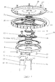
figure 4 est une vue en perspective éclatée illustrant un exemple de montage d'une roue d'ouverture sur un arbre d'entraînement, - la
figure 5 est une vue en coupe axiale de cet exemple de montage, - la
figure 6 est une vue en plan de lafigure 5 .
- the
figure 1 is a front view illustrating an example of possible positioning of the opening wheels in the stacks of toothed disks or saw teeth of a pruning machine cutting head, - the
figure 2 is an overview in perspective showing the positioning of this cutting head in a row of vines, - the
FIGS. 3A, 3B, 3C, 3D, 3E are plan views illustrating the movements of the stacks of the cutting head at the passage of a stake, - the
figure 4 is an exploded perspective view illustrating an example of mounting an opening wheel on a drive shaft, - the
figure 5 is an axial sectional view of this mounting example, - the
figure 6 is a plan view of thefigure 5 .
On se reporte auxdits dessins pour décrire un exemple intéressant, quoique nullement limitatif, de réalisation du dispositif d'ouverture de la tête de coupe selon l'invention.Referring to said drawings to describe an interesting example, although not limiting, of embodiment of the opening device of the cutting head according to the invention.
On souligne que, dans la présente description et dans les revendications, l'expression « haie fruitière » désigne un rang ou alignement d'arbustes fruitiers qui peuvent être d'espèces variées cultivées sur un palissage ou sur des tuteurs, tels que des rangs de vignes.It is pointed out that in the present description and in the claims, the term "fruit hedge" refers to a row or alignment of fruiting shrubs which may be of various species grown on a trellis or on stakes, such as rows of vines.
La tête de coupe de la machine de prétaillage illustrée à la
Ce berceau vertical pivotant est lui-même suspendu, de manière pendulaire et connue en soi, à un bras porteur relié de manière articulée au châssis 3 de la tête de coupe.This pivoting vertical cradle is itself suspended, in a pendular manner and known per se, to a support arm hingedly connected to the
Sur chacun des arbres d'entraînement verticaux 1A, 1 B, sont montés des disques de coupe dentés ou scies circulaires 4, empilés sur lesdits arbres, à distance, de préférence régulière, les uns des autres. De manière connue en soi et comme indiqué précédemment, les empilements 4A, 4B sont décalés en direction verticale, de sorte que les disques de coupe dentés s'interpénètrent en position rapprochée desdits empilements ou position de fermeture de la tête de coupe. Plus précisément, les disques de coupe dentés de l'empilement droit 4A et les disques de coupe dentés de l'empilement gauche 4B se croisent, dans le plan horizontal, sur une distance de quelques centimètres, par exemple sur une distance de l'ordre de 5 cm.On each of the
Au moins une roue d'ouverture tournante 5A, 5B, est montée autour de chaque arbre vertical 1A, 1B, ces roues d'ouverture étant entraînées en rotation par lesdits arbres.At least one
Le pivotement en sens inverse des berceaux porteurs 2A, 2B entraîne :
- soit le rapprochement des empilements de coupe en position de travail,
- soit l'écartement de ces derniers en position de contournement des piquets P1 du palissage P de la haie fruitière H.
- the approach of the cutting stacks in the working position,
- or the spacing of the latter in the bypass position of the stakes P1 of the trellis P of the fruit hedge H.
Selon une disposition caractéristique de l'invention, chaque roue d'ouverture est montée sur son arbre d'entraînement 1A, 1B, par l'intermédiaire d'un réducteur de vitesse accouplé en rotation audit arbre.According to a characteristic arrangement of the invention, each opening wheel is mounted on its
Selon une autre disposition caractéristique avantageuse, ces réducteurs de vitesse sont constitués par des réducteurs à train épicycloïdal.According to another advantageous characteristic arrangement, these speed reducers consist of planetary reduction gears.
Chacun de ces réducteurs à train épicycloïdal 20 comprend (
un planétaire d'entrée 6 entraîné enrotation par 1B dont il est solidaire en rotation au moyen d'un accouplement 1 a-6a ;l'arbre 1A ou- quatre paliers emmanchés sur le planétaire 6, deux paliers 7a sur la partie supérieure et deux paliers 7b sur la partie inférieure dudit planétaire 6 ;
un flasque 8 emmanché sur les deux paliers inférieurs 7b et sur lequel sont fixés, d'une part un deuxième planétaire de sortie 9, au moyen de vis 10, et, d'autre part,une queue d'arrêt 11 au moyen de vis 12, cette queue d'arrêt 11 prenant appui sur letube 13 de section polygonale (par exemple quadrangulaire) du berceauvertical 2B de la tête de coupe de façon à immobiliser enpivotant 2A ourotation le planétaire 9 ;un porte satellites 15 emmanché sur les deux paliers supérieurs 7a ;- trois
satellites 16 équipés d'un palier lisse 17 et montés sur leporte satellite 15.
- an
input sun gear 6 driven in rotation by theshaft - four bearings fitted on the
sun gear 6, two bearings 7a on the upper part and twobearings 7b on the lower part of saidsun gear 6; - a
flange 8 fitted on the twolower bearings 7b and on which are fixed, on the one hand a secondoutput sun gear 9, by means ofscrews 10, and on the other hand, astop tail 11 by means ofscrews 12, thisstop tail 11 bearing on thetube 13 of polygonal section (for example quadrangular) of thevertical pivoting cradle sun gear 9; - a
satellite gate 15 fitted on the two upper bearings 7a; - three
satellites 16 equipped with a sliding bearing 17 and mounted on thesatellite door 15.
Les satellites 16 sont en prise : - d'une part, avec la denture du planétaire 6 et, d'autre part, avec la denture du planétaire 9 constitué par une couronne circulaire dentée intérieurement.The
Selon un mode d'exécution préféré, le rapport de réduction du réducteur de vitesse et, notamment, le rapport de réduction du réducteur à train épicycloïdal décrit ci-dessus, est de 1/2. Ce rapport de réduction permet d'obtenir une vitesse de rotation entre le planétaire 6 et le porte satellite 15 telle que V2 = V1 : 2, dans lequel :
- V1 = vitesse de rotation des arbres d'entraînement 1A, 1 B,
- V2 = vitesse de rotation des roues d'ouverture 5A, 5B.
- V1 = rotational speed of
drive shafts - V2 = speed of rotation of the opening
wheels
Le porte satellite 15 des roues d'ouverture 5A, 5B, qui a un diamètre supérieur au diamètre des disques de coupe dentés 4, prend appui et s'enroule sur les piquets P1 du palissage P, lors de l'avancement de la machine de prétaillage sur la haie fruitière H avec une vitesse de rotation V2 qui aura été préalablement réglée par l'utilisateur pour correspondre sensiblement à la vitesse d'avancement de la machine afin de n'exercer aucune force de poussée ou de tirage sur lesdits piquets.The
On comprend que selon l'agencement du réducteur à train épicycloïdal illustré aux
Les empilements de coupe 4A, 4B, tournent à une vitesse de rotation V1 deux fois supérieure à la vitesse de rotation V2 des roues d'ouverture et permettent un prétaillage et un émiettage des bois ou sarments d'excellente qualité, ainsi qu'un bon nettoyage des fils du palissage de la haie fruitière. Par exemple, les disques de coupe tournent à 200 tr/mn, tandis que les roues d'ouverture tournent à 100 tr/mn.The cutting stacks 4A, 4B rotate at a rotational speed V1 two times greater than the rotation speed V2 of the opening wheels and allow preassembly and crumbling of the woods or vines of excellent quality, as well as a good cleaning the trellis wires of the fruit hedge. For example, the cutting discs rotate at 200 rpm, while the opening wheels rotate at 100 rpm.
Selon une autre disposition caractéristique avantageuse de l'invention, l'une des faces de la roue d'ouverture 5A, 5B, de chaque empilement 4A, 4B est agencée pour constituer une contre-lame qui, en position active rapprochée desdits empilements, se trouve disposée face à l'une des surfaces opposées de la zone périphérique de l'un des disques de coupe 4 de l'empilement opposé 4B, 4A.According to another advantageous characteristic arrangement of the invention, one of the faces of the
De la sorte, on obtient une action de coopération entre la roue d'ouverture et le disque de coupe disposé en vis-à-vis avec un léger décalage dans le sens vertical, et la haie fruitière peut être prétaillée sur toute la hauteur des empilements 4A et 4B.In this way, a cooperation action is obtained between the opening wheel and the cutting disc disposed vis-a-vis with a slight offset in the vertical direction, and the fruit hedge can be pre-pruned over the entire height of the stacks. 4A and 4B.
Selon le mode d'exécution illustré aux
La contre-lame 18 est munie, périphériquement et alternativement, de dents 21 et d'entailles 22.The
La périphérie de chaque roue d'ouverture 5A, 5B, qui peut être avantageusement constituée par le porte satellite 15 du réducteur à train épicycloïdal 20, présente une conformation identique à celle de la contre-lame 18.The periphery of each
Une faible distance est ménagée entre la contre-lame 18 des roues d'ouverture 5A, 5B, et le disque de coupe denté 4 placé en vis-à-vis avec un léger décalage vertical, cette distance est, par exemple, de l'ordre de 10 mm.A small distance is provided between the
De manière préférée, la contre-lame est disposée sur la face supérieure du réducteur à train épicycloïdal constituée par le porte-satellite 15 et elle est placée en vis-à-vis de la face inférieure du disque 4 de l'empilement opposé auquel elle est associée.Preferably, the counterblade is disposed on the upper face of the epicyclic gearbox formed by the
Les
Sur la
La
Sur la
Sur la
La
Claims (12)
Applications Claiming Priority (1)
| Application Number | Priority Date | Filing Date | Title |
|---|---|---|---|
| FR1003783A FR2965145B1 (en) | 2010-09-24 | 2010-09-24 | AUTOMATIC BYPASSING DEVICE FOR FRESH HEDGE FENCE LATCHES AND AGRICULTURAL MACHINERY BY APPLYING |
Publications (3)
| Publication Number | Publication Date |
|---|---|
| EP2433488A2 true EP2433488A2 (en) | 2012-03-28 |
| EP2433488A3 EP2433488A3 (en) | 2012-10-03 |
| EP2433488B1 EP2433488B1 (en) | 2013-11-27 |
Family
ID=43828440
Family Applications (1)
| Application Number | Title | Priority Date | Filing Date |
|---|---|---|---|
| EP11358009.6A Active EP2433488B1 (en) | 2010-09-24 | 2011-08-30 | Device for automatically pass around posts for tying berry hedges, and corresponding agricultural machines |
Country Status (5)
| Country | Link |
|---|---|
| US (1) | US8230671B2 (en) |
| EP (1) | EP2433488B1 (en) |
| AU (1) | AU2011218740B2 (en) |
| ES (1) | ES2445542T3 (en) |
| FR (1) | FR2965145B1 (en) |
Cited By (3)
| Publication number | Priority date | Publication date | Assignee | Title |
|---|---|---|---|---|
| CN102907269A (en) * | 2012-11-15 | 2013-02-06 | 中国农业大学 | Grape residual branch pruning machine |
| CN104686211A (en) * | 2015-03-11 | 2015-06-10 | 汪涛 | Road greening equipment using motor driving device and application method of road greening equipment |
| EP3504961A1 (en) * | 2017-12-29 | 2019-07-03 | CNH Industrial France | Process for pruning a row of plants supported by posts |
Families Citing this family (11)
| Publication number | Priority date | Publication date | Assignee | Title |
|---|---|---|---|---|
| FR2976447B1 (en) * | 2011-06-20 | 2013-07-12 | Jean-Yves Deze | MACHINE FOR AUTOMATICALLY SQUEEZING VINE SIZES |
| US9247691B2 (en) * | 2012-06-27 | 2016-02-02 | Sunview Vineyards Of California | Device for pruning plant growth |
| FR3016494B1 (en) * | 2014-01-17 | 2016-01-08 | Pellenc Sa | ROTARY ATTRACTION DRUM ADJUSTED FOR PLANT CLEANING AND BLANKET HEADS EQUIPPED WITH SUCH A DRUM. |
| JP6651291B2 (en) * | 2015-02-27 | 2020-02-19 | 株式会社アイデック | Mower |
| CN104641964A (en) * | 2015-03-11 | 2015-05-27 | 包宇青 | Road greening equipment with side face cutting function and application method thereof |
| CN104620873A (en) * | 2015-03-11 | 2015-05-20 | 陈园婷 | Road greening equipment with cooling fan and application method of road greening equipment |
| CN106489558A (en) * | 2016-11-07 | 2017-03-15 | 江苏建筑职业技术学院 | Shrub top surface is adjustable five lobe grooves are with pentagon groove and the trimmer deposited |
| US11864497B2 (en) * | 2017-06-30 | 2024-01-09 | Cameron Schiller | Pruning apparatus |
| CN108895124B (en) * | 2018-06-27 | 2020-04-03 | 浙江理工大学 | Planetary gear transmission hedge trimmer transmission and shearing mechanism |
| FR3111764B1 (en) * | 2020-06-24 | 2022-09-02 | Etablissements Collard | Stripper |
| USD984488S1 (en) * | 2021-02-15 | 2023-04-25 | Etablissements Collard | Oval-shaped pneumatic stripping head for a leaf removal machine |
Citations (3)
| Publication number | Priority date | Publication date | Assignee | Title |
|---|---|---|---|---|
| EP0147344A2 (en) | 1983-11-14 | 1985-07-03 | Etablissements Pellenc Et Motte | Cutting device for use in agriculture, viticulture and arboriculture |
| FR2635251A1 (en) | 1988-08-12 | 1990-02-16 | Pieroth Udo | DEVICE FOR CUTTING SWEATHING ON VINE STEWS WITH CORD CULTURE |
| US20060162309A1 (en) | 2005-01-25 | 2006-07-27 | Oxbo International Corporation | Cutter apparatus |
Family Cites Families (11)
| Publication number | Priority date | Publication date | Assignee | Title |
|---|---|---|---|---|
| US1802358A (en) * | 1925-08-26 | 1931-04-28 | Coldwell Lawn Mower Company | Lawn mower |
| US3035675A (en) * | 1958-11-10 | 1962-05-22 | Sunbeam Corp | Overload clutch for power lawn mower |
| US3777463A (en) * | 1972-09-25 | 1973-12-11 | Up Right Inc | Fruit-harvesting machine and conveyor therefor |
| US4543775A (en) * | 1979-04-23 | 1985-10-01 | Up-Right, Inc. | Method and apparatus for pruning cordon-trained grape vines |
| US5259177A (en) * | 1991-07-30 | 1993-11-09 | Donald Windemuller | Blueberry picking machine |
| US5339612A (en) * | 1992-08-31 | 1994-08-23 | Fmc Corporation | Self-adjusting force balance radial grape and raisin harvester |
| FR2723507A1 (en) * | 1994-08-11 | 1996-02-16 | Binger France Sarl | CUTTING MACHINE THAT CAN BE USED IN PARTICULAR FOR PRUNING OR PRUNING OF PALISSE VINES |
| FR2730378B1 (en) * | 1995-02-15 | 1998-11-27 | Pellenc Sa | MACHINE FOR AUTOMATIC OR SEMI-AUTOMATIC PRE-TAILING OR PRUNING OF VINES AND PALISSE TREES OR TREES |
| US6523337B2 (en) * | 2000-04-20 | 2003-02-25 | F&T Spagnolo Tty Ltd. | SG pruning machine |
| FR2921790B1 (en) * | 2007-10-09 | 2009-11-13 | Pellenc Sa | METHOD AND MACHINE FOR THE AUTOMATIC SIZE OF THE VINEYARD. |
| JP5270269B2 (en) * | 2008-09-05 | 2013-08-21 | 株式会社Ihiシバウラ | Power transmission mechanism of walking lawn mower |
-
2010
- 2010-09-24 FR FR1003783A patent/FR2965145B1/en not_active Expired - Fee Related
-
2011
- 2011-08-26 US US13/218,778 patent/US8230671B2/en active Active
- 2011-08-30 ES ES11358009.6T patent/ES2445542T3/en active Active
- 2011-08-30 EP EP11358009.6A patent/EP2433488B1/en active Active
- 2011-09-02 AU AU2011218740A patent/AU2011218740B2/en not_active Ceased
Patent Citations (3)
| Publication number | Priority date | Publication date | Assignee | Title |
|---|---|---|---|---|
| EP0147344A2 (en) | 1983-11-14 | 1985-07-03 | Etablissements Pellenc Et Motte | Cutting device for use in agriculture, viticulture and arboriculture |
| FR2635251A1 (en) | 1988-08-12 | 1990-02-16 | Pieroth Udo | DEVICE FOR CUTTING SWEATHING ON VINE STEWS WITH CORD CULTURE |
| US20060162309A1 (en) | 2005-01-25 | 2006-07-27 | Oxbo International Corporation | Cutter apparatus |
Cited By (5)
| Publication number | Priority date | Publication date | Assignee | Title |
|---|---|---|---|---|
| CN102907269A (en) * | 2012-11-15 | 2013-02-06 | 中国农业大学 | Grape residual branch pruning machine |
| CN102907269B (en) * | 2012-11-15 | 2013-08-07 | 中国农业大学 | Grape residual branch pruning machine |
| CN104686211A (en) * | 2015-03-11 | 2015-06-10 | 汪涛 | Road greening equipment using motor driving device and application method of road greening equipment |
| EP3504961A1 (en) * | 2017-12-29 | 2019-07-03 | CNH Industrial France | Process for pruning a row of plants supported by posts |
| WO2019129888A1 (en) * | 2017-12-29 | 2019-07-04 | Cnh Industrial France S.A.S. | Process for pruning a row of plants supported by posts |
Also Published As
| Publication number | Publication date |
|---|---|
| AU2011218740A1 (en) | 2012-04-12 |
| FR2965145B1 (en) | 2012-10-05 |
| FR2965145A1 (en) | 2012-03-30 |
| US8230671B2 (en) | 2012-07-31 |
| US20120073257A1 (en) | 2012-03-29 |
| EP2433488A3 (en) | 2012-10-03 |
| ES2445542T3 (en) | 2014-03-03 |
| AU2011218740B2 (en) | 2014-07-17 |
| EP2433488B1 (en) | 2013-11-27 |
Similar Documents
| Publication | Publication Date | Title |
|---|---|---|
| EP2433488B1 (en) | Device for automatically pass around posts for tying berry hedges, and corresponding agricultural machines | |
| EP0147344B1 (en) | Cutting device for use in agriculture, viticulture and arboriculture | |
| EP0696416B1 (en) | Cutting machine to be used especially for pruning and pre-pruning tied vines | |
| FR2565772A1 (en) | APPARATUS FOR PRUNING VINES | |
| FR2542565A1 (en) | ROTARY MOWER | |
| EP2720528B1 (en) | Machine for automatically pulling cut vine stems | |
| FR2917944A1 (en) | Pre-pruner for e.g. vine, has cutting assemblies fixed with respect to each other on width equal to that of notches of cutting disks for creating blade and counter-blade effect, where notches are joined and tapered on their length | |
| FR2730378A1 (en) | MACHINE FOR AUTOMATIC OR SEMI-AUTOMATIC PRE-TAILING OR PRUNING OF VINES AND PALISSE TREES OR TREES | |
| EP1825744B1 (en) | Cutting machine used mainly in agriculture, arboriculture and viticulture | |
| FR2752360A1 (en) | Implement for harvesting grapes | |
| FR2576481A1 (en) | Vine pruner attachment for tractor | |
| EP2382860A1 (en) | Pre-pruner | |
| EP2433487B1 (en) | Element and machine for cutting and picking plants, work vehicle comprising such an element or such a machine and method for cutting and picking plants | |
| EP2095704B1 (en) | Cutting machine used mainly in viticulture, equipped with a tool for tendrils and a sharpening device | |
| FR2893816A1 (en) | PREAILLEUSE INCORPORATING MEANS OF BYPASS CIRCUITS OR THE LIKE | |
| FR2975867A1 (en) | ELAGUEUSE | |
| FR2781977A1 (en) | Automatic tree pruning saw comprises hinged frame fitting around trunk, drive wheels and circular saw for pruning projecting branches | |
| EP2727457B1 (en) | Cutting machine | |
| EP1026940B1 (en) | Device for lopping branches | |
| FR2779905A1 (en) | Cutting head for pruning trees or shrubs | |
| FR3055515A1 (en) | A MACHINE FOR DRAWING VINE SARA, AN AGRICULTURAL VEHICLE AND USE THEREOF | |
| FR2458987A1 (en) | Machine for cutting grass - has upper and lower contra rotating belts driven by pulleys and fitted with flexible wires to provide continuous cutting action |
Legal Events
| Date | Code | Title | Description |
|---|---|---|---|
| PUAI | Public reference made under article 153(3) epc to a published international application that has entered the european phase |
Free format text: ORIGINAL CODE: 0009012 |
|
| AK | Designated contracting states |
Kind code of ref document: A2 Designated state(s): AL AT BE BG CH CY CZ DE DK EE ES FI FR GB GR HR HU IE IS IT LI LT LU LV MC MK MT NL NO PL PT RO RS SE SI SK SM TR |
|
| AX | Request for extension of the european patent |
Extension state: BA ME |
|
| 17P | Request for examination filed |
Effective date: 20120424 |
|
| PUAL | Search report despatched |
Free format text: ORIGINAL CODE: 0009013 |
|
| AK | Designated contracting states |
Kind code of ref document: A3 Designated state(s): AL AT BE BG CH CY CZ DE DK EE ES FI FR GB GR HR HU IE IS IT LI LT LU LV MC MK MT NL NO PL PT RO RS SE SI SK SM TR |
|
| AX | Request for extension of the european patent |
Extension state: BA ME |
|
| RIC1 | Information provided on ipc code assigned before grant |
Ipc: A01G 17/02 20060101ALI20120830BHEP Ipc: A01G 3/04 20060101AFI20120830BHEP |
|
| GRAP | Despatch of communication of intention to grant a patent |
Free format text: ORIGINAL CODE: EPIDOSNIGR1 |
|
| INTG | Intention to grant announced |
Effective date: 20130704 |
|
| GRAS | Grant fee paid |
Free format text: ORIGINAL CODE: EPIDOSNIGR3 |
|
| GRAA | (expected) grant |
Free format text: ORIGINAL CODE: 0009210 |
|
| AK | Designated contracting states |
Kind code of ref document: B1 Designated state(s): AL AT BE BG CH CY CZ DE DK EE ES FI FR GB GR HR HU IE IS IT LI LT LU LV MC MK MT NL NO PL PT RO RS SE SI SK SM TR |
|
| REG | Reference to a national code |
Ref country code: GB Ref legal event code: FG4D Free format text: NOT ENGLISH |
|
| REG | Reference to a national code |
Ref country code: CH Ref legal event code: EP |
|
| REG | Reference to a national code |
Ref country code: AT Ref legal event code: REF Ref document number: 642299 Country of ref document: AT Kind code of ref document: T Effective date: 20131215 |
|
| REG | Reference to a national code |
Ref country code: IE Ref legal event code: FG4D Free format text: LANGUAGE OF EP DOCUMENT: FRENCH |
|
| REG | Reference to a national code |
Ref country code: DE Ref legal event code: R096 Ref document number: 602011003952 Country of ref document: DE Effective date: 20140123 |
|
| REG | Reference to a national code |
Ref country code: ES Ref legal event code: FG2A Ref document number: 2445542 Country of ref document: ES Kind code of ref document: T3 Effective date: 20140303 |
|
| REG | Reference to a national code |
Ref country code: NL Ref legal event code: VDEP Effective date: 20131127 |
|
| REG | Reference to a national code |
Ref country code: AT Ref legal event code: MK05 Ref document number: 642299 Country of ref document: AT Kind code of ref document: T Effective date: 20131127 |
|
| REG | Reference to a national code |
Ref country code: LT Ref legal event code: MG4D |
|
| PG25 | Lapsed in a contracting state [announced via postgrant information from national office to epo] |
Ref country code: IS Free format text: LAPSE BECAUSE OF FAILURE TO SUBMIT A TRANSLATION OF THE DESCRIPTION OR TO PAY THE FEE WITHIN THE PRESCRIBED TIME-LIMIT Effective date: 20140327 Ref country code: LT Free format text: LAPSE BECAUSE OF FAILURE TO SUBMIT A TRANSLATION OF THE DESCRIPTION OR TO PAY THE FEE WITHIN THE PRESCRIBED TIME-LIMIT Effective date: 20131127 Ref country code: NO Free format text: LAPSE BECAUSE OF FAILURE TO SUBMIT A TRANSLATION OF THE DESCRIPTION OR TO PAY THE FEE WITHIN THE PRESCRIBED TIME-LIMIT Effective date: 20140227 Ref country code: HR Free format text: LAPSE BECAUSE OF FAILURE TO SUBMIT A TRANSLATION OF THE DESCRIPTION OR TO PAY THE FEE WITHIN THE PRESCRIBED TIME-LIMIT Effective date: 20131127 Ref country code: NL Free format text: LAPSE BECAUSE OF FAILURE TO SUBMIT A TRANSLATION OF THE DESCRIPTION OR TO PAY THE FEE WITHIN THE PRESCRIBED TIME-LIMIT Effective date: 20131127 Ref country code: SE Free format text: LAPSE BECAUSE OF FAILURE TO SUBMIT A TRANSLATION OF THE DESCRIPTION OR TO PAY THE FEE WITHIN THE PRESCRIBED TIME-LIMIT Effective date: 20131127 Ref country code: FI Free format text: LAPSE BECAUSE OF FAILURE TO SUBMIT A TRANSLATION OF THE DESCRIPTION OR TO PAY THE FEE WITHIN THE PRESCRIBED TIME-LIMIT Effective date: 20131127 |
|
| PG25 | Lapsed in a contracting state [announced via postgrant information from national office to epo] |
Ref country code: RS Free format text: LAPSE BECAUSE OF FAILURE TO SUBMIT A TRANSLATION OF THE DESCRIPTION OR TO PAY THE FEE WITHIN THE PRESCRIBED TIME-LIMIT Effective date: 20131127 Ref country code: CY Free format text: LAPSE BECAUSE OF FAILURE TO SUBMIT A TRANSLATION OF THE DESCRIPTION OR TO PAY THE FEE WITHIN THE PRESCRIBED TIME-LIMIT Effective date: 20131127 Ref country code: AT Free format text: LAPSE BECAUSE OF FAILURE TO SUBMIT A TRANSLATION OF THE DESCRIPTION OR TO PAY THE FEE WITHIN THE PRESCRIBED TIME-LIMIT Effective date: 20131127 Ref country code: LV Free format text: LAPSE BECAUSE OF FAILURE TO SUBMIT A TRANSLATION OF THE DESCRIPTION OR TO PAY THE FEE WITHIN THE PRESCRIBED TIME-LIMIT Effective date: 20131127 |
|
| PG25 | Lapsed in a contracting state [announced via postgrant information from national office to epo] |
Ref country code: PT Free format text: LAPSE BECAUSE OF FAILURE TO SUBMIT A TRANSLATION OF THE DESCRIPTION OR TO PAY THE FEE WITHIN THE PRESCRIBED TIME-LIMIT Effective date: 20140327 |
|
| PG25 | Lapsed in a contracting state [announced via postgrant information from national office to epo] |
Ref country code: EE Free format text: LAPSE BECAUSE OF FAILURE TO SUBMIT A TRANSLATION OF THE DESCRIPTION OR TO PAY THE FEE WITHIN THE PRESCRIBED TIME-LIMIT Effective date: 20131127 |
|
| REG | Reference to a national code |
Ref country code: DE Ref legal event code: R097 Ref document number: 602011003952 Country of ref document: DE |
|
| PG25 | Lapsed in a contracting state [announced via postgrant information from national office to epo] |
Ref country code: CZ Free format text: LAPSE BECAUSE OF FAILURE TO SUBMIT A TRANSLATION OF THE DESCRIPTION OR TO PAY THE FEE WITHIN THE PRESCRIBED TIME-LIMIT Effective date: 20131127 Ref country code: SK Free format text: LAPSE BECAUSE OF FAILURE TO SUBMIT A TRANSLATION OF THE DESCRIPTION OR TO PAY THE FEE WITHIN THE PRESCRIBED TIME-LIMIT Effective date: 20131127 Ref country code: PL Free format text: LAPSE BECAUSE OF FAILURE TO SUBMIT A TRANSLATION OF THE DESCRIPTION OR TO PAY THE FEE WITHIN THE PRESCRIBED TIME-LIMIT Effective date: 20131127 Ref country code: RO Free format text: LAPSE BECAUSE OF FAILURE TO SUBMIT A TRANSLATION OF THE DESCRIPTION OR TO PAY THE FEE WITHIN THE PRESCRIBED TIME-LIMIT Effective date: 20131127 |
|
| PG25 | Lapsed in a contracting state [announced via postgrant information from national office to epo] |
Ref country code: DK Free format text: LAPSE BECAUSE OF FAILURE TO SUBMIT A TRANSLATION OF THE DESCRIPTION OR TO PAY THE FEE WITHIN THE PRESCRIBED TIME-LIMIT Effective date: 20131127 |
|
| PLBE | No opposition filed within time limit |
Free format text: ORIGINAL CODE: 0009261 |
|
| STAA | Information on the status of an ep patent application or granted ep patent |
Free format text: STATUS: NO OPPOSITION FILED WITHIN TIME LIMIT |
|
| 26N | No opposition filed |
Effective date: 20140828 |
|
| REG | Reference to a national code |
Ref country code: DE Ref legal event code: R097 Ref document number: 602011003952 Country of ref document: DE Effective date: 20140828 |
|
| PG25 | Lapsed in a contracting state [announced via postgrant information from national office to epo] |
Ref country code: SI Free format text: LAPSE BECAUSE OF FAILURE TO SUBMIT A TRANSLATION OF THE DESCRIPTION OR TO PAY THE FEE WITHIN THE PRESCRIBED TIME-LIMIT Effective date: 20131127 |
|
| PG25 | Lapsed in a contracting state [announced via postgrant information from national office to epo] |
Ref country code: LU Free format text: LAPSE BECAUSE OF FAILURE TO SUBMIT A TRANSLATION OF THE DESCRIPTION OR TO PAY THE FEE WITHIN THE PRESCRIBED TIME-LIMIT Effective date: 20140830 Ref country code: MC Free format text: LAPSE BECAUSE OF FAILURE TO SUBMIT A TRANSLATION OF THE DESCRIPTION OR TO PAY THE FEE WITHIN THE PRESCRIBED TIME-LIMIT Effective date: 20131127 |
|
| REG | Reference to a national code |
Ref country code: CH Ref legal event code: PL |
|
| PG25 | Lapsed in a contracting state [announced via postgrant information from national office to epo] |
Ref country code: CH Free format text: LAPSE BECAUSE OF NON-PAYMENT OF DUE FEES Effective date: 20140831 Ref country code: BE Free format text: LAPSE BECAUSE OF NON-PAYMENT OF DUE FEES Effective date: 20140831 Ref country code: LI Free format text: LAPSE BECAUSE OF NON-PAYMENT OF DUE FEES Effective date: 20140831 |
|
| REG | Reference to a national code |
Ref country code: IE Ref legal event code: MM4A |
|
| PG25 | Lapsed in a contracting state [announced via postgrant information from national office to epo] |
Ref country code: IE Free format text: LAPSE BECAUSE OF NON-PAYMENT OF DUE FEES Effective date: 20140830 |
|
| GBPC | Gb: european patent ceased through non-payment of renewal fee |
Effective date: 20150830 |
|
| PG25 | Lapsed in a contracting state [announced via postgrant information from national office to epo] |
Ref country code: SM Free format text: LAPSE BECAUSE OF FAILURE TO SUBMIT A TRANSLATION OF THE DESCRIPTION OR TO PAY THE FEE WITHIN THE PRESCRIBED TIME-LIMIT Effective date: 20131127 |
|
| PG25 | Lapsed in a contracting state [announced via postgrant information from national office to epo] |
Ref country code: BG Free format text: LAPSE BECAUSE OF FAILURE TO SUBMIT A TRANSLATION OF THE DESCRIPTION OR TO PAY THE FEE WITHIN THE PRESCRIBED TIME-LIMIT Effective date: 20131127 Ref country code: MT Free format text: LAPSE BECAUSE OF FAILURE TO SUBMIT A TRANSLATION OF THE DESCRIPTION OR TO PAY THE FEE WITHIN THE PRESCRIBED TIME-LIMIT Effective date: 20131127 Ref country code: GR Free format text: LAPSE BECAUSE OF FAILURE TO SUBMIT A TRANSLATION OF THE DESCRIPTION OR TO PAY THE FEE WITHIN THE PRESCRIBED TIME-LIMIT Effective date: 20140228 |
|
| REG | Reference to a national code |
Ref country code: FR Ref legal event code: PLFP Year of fee payment: 6 |
|
| PG25 | Lapsed in a contracting state [announced via postgrant information from national office to epo] |
Ref country code: GB Free format text: LAPSE BECAUSE OF NON-PAYMENT OF DUE FEES Effective date: 20150830 Ref country code: HU Free format text: LAPSE BECAUSE OF FAILURE TO SUBMIT A TRANSLATION OF THE DESCRIPTION OR TO PAY THE FEE WITHIN THE PRESCRIBED TIME-LIMIT; INVALID AB INITIO Effective date: 20110830 Ref country code: TR Free format text: LAPSE BECAUSE OF FAILURE TO SUBMIT A TRANSLATION OF THE DESCRIPTION OR TO PAY THE FEE WITHIN THE PRESCRIBED TIME-LIMIT Effective date: 20131127 |
|
| REG | Reference to a national code |
Ref country code: FR Ref legal event code: PLFP Year of fee payment: 7 |
|
| PG25 | Lapsed in a contracting state [announced via postgrant information from national office to epo] |
Ref country code: MK Free format text: LAPSE BECAUSE OF FAILURE TO SUBMIT A TRANSLATION OF THE DESCRIPTION OR TO PAY THE FEE WITHIN THE PRESCRIBED TIME-LIMIT Effective date: 20131127 |
|
| REG | Reference to a national code |
Ref country code: FR Ref legal event code: PLFP Year of fee payment: 8 |
|
| PG25 | Lapsed in a contracting state [announced via postgrant information from national office to epo] |
Ref country code: AL Free format text: LAPSE BECAUSE OF FAILURE TO SUBMIT A TRANSLATION OF THE DESCRIPTION OR TO PAY THE FEE WITHIN THE PRESCRIBED TIME-LIMIT Effective date: 20131127 |
|
| PGFP | Annual fee paid to national office [announced via postgrant information from national office to epo] |
Ref country code: DE Payment date: 20200827 Year of fee payment: 10 |
|
| REG | Reference to a national code |
Ref country code: DE Ref legal event code: R119 Ref document number: 602011003952 Country of ref document: DE |
|
| PG25 | Lapsed in a contracting state [announced via postgrant information from national office to epo] |
Ref country code: DE Free format text: LAPSE BECAUSE OF NON-PAYMENT OF DUE FEES Effective date: 20220301 |
|
| PGFP | Annual fee paid to national office [announced via postgrant information from national office to epo] |
Ref country code: IT Payment date: 20230822 Year of fee payment: 13 Ref country code: ES Payment date: 20230901 Year of fee payment: 13 |
|
| PGFP | Annual fee paid to national office [announced via postgrant information from national office to epo] |
Ref country code: FR Payment date: 20240826 Year of fee payment: 14 |