EP2433447B1 - Compte rendu de marge de puissance pour agrégation de porteuse - Google Patents
Compte rendu de marge de puissance pour agrégation de porteuse Download PDFInfo
- Publication number
- EP2433447B1 EP2433447B1 EP10730881A EP10730881A EP2433447B1 EP 2433447 B1 EP2433447 B1 EP 2433447B1 EP 10730881 A EP10730881 A EP 10730881A EP 10730881 A EP10730881 A EP 10730881A EP 2433447 B1 EP2433447 B1 EP 2433447B1
- Authority
- EP
- European Patent Office
- Prior art keywords
- carriers
- power headroom
- carrier
- pucch
- related information
- Prior art date
- Legal status (The legal status is an assumption and is not a legal conclusion. Google has not performed a legal analysis and makes no representation as to the accuracy of the status listed.)
- Active
Links
Images


Classifications
-
- H—ELECTRICITY
- H04—ELECTRIC COMMUNICATION TECHNIQUE
- H04W—WIRELESS COMMUNICATION NETWORKS
- H04W52/00—Power management, e.g. TPC [Transmission Power Control], power saving or power classes
- H04W52/04—TPC
- H04W52/30—TPC using constraints in the total amount of available transmission power
- H04W52/36—TPC using constraints in the total amount of available transmission power with a discrete range or set of values, e.g. step size, ramping or offsets
- H04W52/365—Power headroom reporting
-
- H—ELECTRICITY
- H04—ELECTRIC COMMUNICATION TECHNIQUE
- H04L—TRANSMISSION OF DIGITAL INFORMATION, e.g. TELEGRAPHIC COMMUNICATION
- H04L5/00—Arrangements affording multiple use of the transmission path
- H04L5/003—Arrangements for allocating sub-channels of the transmission path
- H04L5/0053—Allocation of signaling, i.e. of overhead other than pilot signals
-
- H—ELECTRICITY
- H04—ELECTRIC COMMUNICATION TECHNIQUE
- H04W—WIRELESS COMMUNICATION NETWORKS
- H04W52/00—Power management, e.g. TPC [Transmission Power Control], power saving or power classes
- H04W52/04—TPC
- H04W52/18—TPC being performed according to specific parameters
- H04W52/24—TPC being performed according to specific parameters using SIR [Signal to Interference Ratio] or other wireless path parameters
- H04W52/242—TPC being performed according to specific parameters using SIR [Signal to Interference Ratio] or other wireless path parameters taking into account path loss
-
- H—ELECTRICITY
- H04—ELECTRIC COMMUNICATION TECHNIQUE
- H04W—WIRELESS COMMUNICATION NETWORKS
- H04W52/00—Power management, e.g. TPC [Transmission Power Control], power saving or power classes
- H04W52/04—TPC
- H04W52/30—TPC using constraints in the total amount of available transmission power
- H04W52/34—TPC management, i.e. sharing limited amount of power among users or channels or data types, e.g. cell loading
-
- H—ELECTRICITY
- H04—ELECTRIC COMMUNICATION TECHNIQUE
- H04W—WIRELESS COMMUNICATION NETWORKS
- H04W72/00—Local resource management
- H04W72/20—Control channels or signalling for resource management
-
- H—ELECTRICITY
- H04—ELECTRIC COMMUNICATION TECHNIQUE
- H04W—WIRELESS COMMUNICATION NETWORKS
- H04W72/00—Local resource management
- H04W72/20—Control channels or signalling for resource management
- H04W72/21—Control channels or signalling for resource management in the uplink direction of a wireless link, i.e. towards the network
-
- H—ELECTRICITY
- H04—ELECTRIC COMMUNICATION TECHNIQUE
- H04W—WIRELESS COMMUNICATION NETWORKS
- H04W76/00—Connection management
- H04W76/10—Connection setup
Definitions
- the terms “user agent” and “UA” might in some cases refer to mobile devices such as mobile telephones, personal digital assistants, handheld or laptop computers, and similar devices that have telecommunications capabilities. Such a UA might consist of a device and its associated removable memory module, such as but not limited to a Universal Integrated Circuit Card (UICC) that includes a Subscriber Identity Module (SIM) application, a Universal Subscriber Identity Module (USIM) application, or a Removable User Identity Module (R-UIM) application. Alternatively, such a UA might consist of the device itself without such a module. In other cases, the term “UA” might refer to devices that have similar capabilities but that are not transportable, such as desktop computers, set-top boxes, or network appliances. The term “UA” can also refer to any hardware or software component that can terminate a communication session for a user. Also, the terms “user agent,” “UA,” “user equipment,” “UE,” “user device” and “user node” might be used synonymously herein.
- UICC Universal Integrated Circuit Card
- LTE Long-term evolution
- an LTE system might include an Evolved Universal Terrestrial Radio Access Network (E-UTRAN) node B (eNB), a wireless access point, or a similar component rather than a traditional base station.
- E-UTRAN Evolved Universal Terrestrial Radio Access Network
- eNB Evolved Universal Terrestrial Radio Access Network node B
- wireless access point a wireless access point, or a similar component rather than a traditional base station.
- the term "access node” will refer to any component of a wireless telecommunications system, such as a traditional base station, a wireless access point, or an LTE eNB, that creates a geographical area of reception and transmission coverage allowing a UA to access other components in the system.
- An access node may comprise a plurality of hardware and software.
- LTE was standardized in Release 8 of the wireless telecommunications standards promoted by the 3rd Generation Partnership Project (3GPP). 3GPP Release 10 standards deal with LTE-Advanced or LTE-A technology. Under LTE-A, relays and other advanced components might be included in a wireless telecommunications network.
- a relay is a component in a wireless network that is configured to extend or enhance the coverage created by an access node or another relay.
- access nodes and relays may be distinct components with different capabilities and functions, for ease of reference, the term "access node" will be used herein to refer to either a relay or an access node as described above.
- the signals that carry data between UAs, relay nodes, and access nodes can have frequency, time, and coding parameters and other characteristics that might be specified by a network node.
- a connection between any of these elements that has a specific set of such characteristics can be referred to as a resource.
- the terms "resource”, “communications connection”, “channel”, and “communications link” might be used synonymously herein.
- a network node typically establishes a different resource for each UA or other network node with which it is communicating at any particular time.
- the Samsung document 20090318-XP050338862 relates to uplink transmission power control in LTE.
- the present invention is set out in the independent claims, with some optional features set out in the claims dependent thereto.
- Figure 1 illustrates an aggregation of carriers
- Figure 2 illustrates a procedure by which an access node grants a resource to a user agent.
- Figure 3 is a diagram of a power headroom and related quantities.
- Figure 4 is a diagram of a control element that could be used for transmitting power headroom-related information according to an embodiment of the disclosure.
- Figure 5a is a diagram of a control element that could be used for transmitting power headroom-related information according to an alternative embodiment of the disclosure.
- Figure 5b is a diagram of a control element that could be used for transmitting power headroom-related information according to an alternative embodiment of the disclosure.
- Figure 6 is a diagram of a control element that could be used for transmitting power headroom-related information according to an alternative embodiment of the disclosure.
- Figure 7 is a table showing a mapping between a power difference and a two-bit variable according to an embodiment of the disclosure.
- Figure 8 is a table illustrating a calculation of a power difference between a carrier and a reference carrier according to an embodiment of the disclosure.
- Figure 9 is a diagram of a control element that could be used for transmitting power headroom-related information according to an alternative embodiment of the disclosure.
- Figure 10 is a diagram of a control element that could be used for transmitting power headroom-related information according to an alternative embodiment of the disclosure.
- Figure 11 illustrates an exemplary MAC control element according to an embodiment of the disclosure.
- Figure 12 is a diagram illustrating a method for reporting power headroom-related information for a plurality of aggregated carriers according to an embodiment of the disclosure.
- Figure 13 illustrates a processor and related components suitable for implementing the several embodiments of the present disclosure.
- carrier aggregation might be used in order to support wider transmission bandwidths and hence increase the potential peak data rate to meet LTE-A requirements.
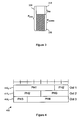
- carrier aggregation multiple component carriers are aggregated and can be allocated in a subframe to a UA as shown in Figure 1 .
- each component carrier 110 has a width of 20 MHz and the total system bandwidth becomes 100 MHz.
- the UA may receive or transmit on a multiple of up to five component carriers depending on its capabilities.
- carrier aggregation may occur with carriers located in the same band and/or carriers located in different bands. For example, one carrier may be located at 2 GHz and a second aggregated carrier may be located at 800 MHz.
- a UA transmits a power headroom report (PHR) and a buffer status report (BSR) to an access node in order to assist with uplink scheduling.
- the access node uses this information when it determines the amount of frequency resources and proper modulation and coding scheme (MCS) level for physical uplink shared channel (PUSCH) transmissions.
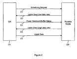
- FIG 2 shows the general flow of an uplink transmission from a UA 210 to an access node 220.
- the UA 210 transmits a scheduling request on the physical uplink control channel (PUCCH) if there is no uplink PUSCH resource available for the initial transmission.
- PUCCH physical uplink control channel
- the access node 220 Since the access node 220 does not know the current uplink channel conditions or the amount of pending data, the access node 220 schedules a small amount of uplink resources, as shown at event 232. The UA 210, at event 233, then transmits a PHR and BSR using this initial uplink resource. With this additional information, the access node 220, at event 234, can provide the UA 210 with a larger amount of uplink resources. At event 235, the UA 210 transmits to the access node 220 at a higher data rate according to the UA buffer status and the observed channel conditions.
- the power headroom (PH) 310 is defined as the difference between the nominal UA maximum transmit power (P cmax ) 320 and the estimated power for PUSCH transmissions (P pusch(i) ) 330.
- P cmax the nominal UA maximum transmit power
- P pusch(i) the estimated power for PUSCH transmissions
- the PH values can be different depending on the current UA channel conditions. From the access node scheduler's point of view, a large PH means that the UA has more room to increase its power to accommodate a higher data rate transmission, while a small PH means that the UA cannot increase its data rate.
- P CMAX is the configured maximum UA transmission power.
- M PUSCH (i) is the bandwidth of the PUSCH resource assignment expressed in number of resource blocks scheduled for subframe i .
- P O_PUSCH ( j ) is a parameter composed of the sum of a cell-specific nominal component and a UA-specific component provided by higher layers.
- ⁇ ( j ) is defined in 3GPP TS 36.213.
- PL is the downlink path loss estimate calculated in the UA in dB.
- ⁇ TF ( i ) is the offset with respect to the transport format.
- f ( i ) is the power control adjustment.
- UAs In LTE-A systems, UAs might report their PH to an access node to assist with uplink scheduling as in the case with LTE systems.
- the PH reporting approach used in LTE where PH is the difference between the maximum allowable and current uplink transmission powers, may not be appropriate in LTE-A.
- An LTE-A UA is able to transmit using multiple carriers simultaneously, and scheduling might be performed on a per-carrier basis with different MCS levels. If each carrier is constrained to use the same uplink transmit power, one PH report may be sufficient. However, the uplink transmit power would be expected to be different for each carrier because some power-related parameters might vary for different carriers.
- the path loss can be different if the carriers are located in different bands. Assuming two example carriers are located at 2 GHz and 800 MHz, respectively, the expected statistical difference in path loss can be calculated as a function of the frequency based on the path loss model in 3GPP Technical Report (TR) 25.942.
- the path loss L is given as 40(1 - 4x10 -3 Dhb) Log 10 (R) - 18Log 10 (Dhb) + 21Log 10 (f) + 80 dB, where f is the frequency in MHz, Dhb is the access node antenna height in meters (in 3GPP, 15m is assumed), and R is the distance between the access node and the UA in kilometers.
- the power control adjustment, f(i) might be different for different carriers.
- An access node could transmit individual TPC (Transmit Power Control) commands per carrier or a single combined TPC command for all of the carriers. Even though the access node originates the TPC commands, it would be difficult for the access node to correctly track the current f(i) values per carrier due to possible TPC signaling errors and/or TPC signals that were mis-detected by the UA.
- TPC Transmit Power Control
- P O_PUSCH might vary for different carriers.
- P O_PUSCH is a cell- and UA-specific parameter that adjusts the target signal to interference-plus-noise ratio (SINR) based on the interference level. Since each component carrier is scheduled independently, each carrier might experience a different inter-cell interference level. The loading of different carriers may be different depending on the scheduling in the neighbor cells. For example, the access node might schedule cell-edge UAs on one carrier and more centrally-located UAs on the remaining carriers.
- the network topology may result in different neighboring cells having different carriers available. For instance, one cell may have five carriers in total, but a neighboring cell that is expected to be less lightly loaded may only be configured with a maximum of three carriers.
- ⁇ (j) might be different for different carriers.
- ⁇ (j) is a cell-specific parameter intended to improve cell throughput under small interference levels. This parameter can be varied based on the cell loading and/or on the UA distribution within a cell.
- the uplink transmit power, and therefore the power headroom, might be different for each carrier in a set of aggregated carriers.
- the PH of all carriers could be reported to the access node.
- this could result in excessive signaling overhead, since it may not be necessary to report the PH for every carrier.
- various schemes are provided for efficiently transmitting per-carrier PH values for a set of aggregated carriers in order to reduce signaling overhead.
- a PH value Most of the factors determining a PH value are carrier-specific but, other than path loss (and possibly the current power control correction), the access node is typically aware of these parameters. Therefore, if the access node is made aware of the path loss for each carrier, the access node can calculate a PH for each carrier.
- a UA could report an observed path loss in a higher-layer measurement report, but such a report may not be sent frequently enough because higher-layer messages tend to be larger and generally incur some delay before being triggered. Consequently, it may be advantageous for the UA to report a separate PH value to the access node for each carrier. However, it may be unnecessary to report separate PH values for all carriers given that the path losses of carriers located in the same frequency band are typically similar.
- the number of carriers for which the PH or PH-related information is reported is less than or equal to the total number of configured carriers.
- a carrier for which a PH or PH-related information is reported is referred to herein as a "reporting carrier".
- a UA determines which carriers are reporting carriers based on whether the carriers are located in the same band or not. If a PH report has been triggered by one of the triggering criteria described below, and if there are multiple carriers in the same band, the UA can select the reporting carrier using a predefined set of rules known by both the access node and UA. For example, the UA might choose the carrier having the lowest centre frequency, the carrier having the lowest physical cell ID, or some other carrier or carriers. Since the access node already knows whether or not the configured carriers are located in the same band, the UA does not have to signal its decision to the access node. The access node is aware of this predefined rule and can utilize the PH reporting correctly.
- an access node configures the carrier set to be reported.
- the access node selects the carriers for which PH reporting will be performed and communicates this decision to the UA via radio resource control (RRC) signaling or media access control (MAC) control elements.
- RRC radio resource control
- MAC media access control
- a PH report might be transmitted at periodic intervals and/or when a triggering event occurs.
- a PH report is triggered if any of the following events occur: the prohibitPHR- Timer expires or has expired and the path loss has changed more than dl-PathlossChange dB since the last power headroom report, when the UA has uplink resources for a new transmission; the periodicPHR-Timer expires, in which case the PHR is referred to as a "Periodic PHR"; upon configuration and reconfiguration of a Periodic PHR.
- these criteria are expanded to support carrier aggregation under LTE-A.
- the triggers related to the expiration of the periodicPHR-Timer and the configuration and reconfiguration of a Periodic PHR might remain the same, but the trigger related to the expiration of the prohibitPHR-Timer might be modified.
- a PH report is triggered if the prohibitPHR-Timer expires or has expired and the path loss of any reporting carrier has changed more than dl-PathlossChange dB since the last power headroom report, when the UA has uplink resources for a new transmission.
- the PH reporting scheme could be such that only reporting carriers that satisfy this dl-PathlossChange criterion actually report their new PH values. That is, not all configured reporting carriers would actually include their PH values in the PH report.
- a PH report is triggered when a UA receives a new carrier configuration from the access node and/or a new PH reporting configuration that includes a new reporting carrier.
- a UA could transmit a PH report to an access node via RRC signaling or via MAC control elements. Since the RRC signaling approach might incur additional delay and signaling overhead, the MAC control element approach may be preferable.
- the following alternatives for transmitting a PH or PH-related information are based on the MAC control element approach. If there is no explicit indication otherwise, the PH reporting discussed in the following alternatives is triggered according to the criteria described above.
- a UA when PH reporting is triggered, transmits the PHs for all of the reporting carriers. For example, if there are four reporting carriers, when the observed path loss difference for one of the reporting carriers exceeds the configured threshold (that is, the path loss of a reporting carrier has changed more than dl-PathlossChange dB), the UA transmits the PHs for all four of the reporting carriers.
- FIG. 4 illustrates an example of a MAC control element 400 that could be used for transmitting the PHs of all reporting carriers.
- the control element 400 consists of three byte-aligned octets 410.
- the number of PH values equals the number of reporting carriers. In this example four reporting carriers have been configured.
- the length of the PH values is six bits, as in LTE.
- Each PH k represents the PH of carrier k .
- the UA can decide not to transmit all PHs or transmit PHs of a subset of carriers in the MAC control element to be accommodated in the allocated UL resources.
- the UA can select carriers based on the logical or physical carrier indexing. In one embodiment, the UA can select a carrier based on the priority of the carrier. For example, the UA can transmit the PH of the uplink anchor carrier or a carrier used to transmit data with a high quality of service (QoS).
- QoS quality of service
- a UA transmits a PH report in a long format or a short format depending on the situation. That is, to reduce signaling overhead, two different kinds of PH report can be defined: a wideband PH report and a per-carrier PH report.
- the wideband PH report represents the power situation across the system bandwidth and could be generated by averaging the PH values of all carriers, could include the PH of a certain representative carrier, or could represent the system-wide power in some other manner.
- This wideband PH report could be transmitted in a MAC control element, and the existing LTE format could be re-used because the wideband PH report includes only one PH value.
- the PH of each carrier could be transmitted as described above.
- the PH reports could be configured using one of two different techniques.
- different reporting periodicities are configured for each type of report, with the wideband PH being reported more often than the per-carrier PHs. For example, a wideband PH might be reported every 10 milliseconds, and per-carrier PHs might be reported every 100 milliseconds.
- the UA transmits per-carrier PH information if the PH difference between different reporting carriers or the difference between per carrier PHs and the wideband PH are larger than a preset threshold. Otherwise, the UA transmits a wideband PH report. This threshold could be configured by higher-layer signaling.
- the UA could indicate whether the PH report is of the wideband or per-carrier PH format by including a 1-bit indicator before the PH values.
- Sample control element formats that could be used in the second technique are shown in Figures 5a and 5b .
- the control elements consist of byte-aligned octets
- the length of the PH values is six bits
- reserved bits and/or padding bits can be used for byte alignment.
- a one-bit indicator 510 is included at the beginning of the control element 500.
- One value for this indicator 510 indicates that this control element 500 includes only a wideband PH.
- a padding bit 520 is then included, and then a PH value 530 that represents the power situation across the system bandwidth is included.
- the one-bit indicator 510 is again included at the beginning of the control element 550.
- the alternative value for this indicator 510, "0" in this example, indicates that this control element 550 includes PH values for all reporting carriers.
- a padding bit 520 is then included, followed by the PH values 560 for the reporting carriers in a manner similar to that depicted in Figure 4 . Additional padding bits 520 then fill out the last octet.
- a UA transmits the PH value for one carrier and PH-related information for the remaining carriers at the same time.
- one of two techniques could be used to transmit PH information for all reporting carriers.
- a UA transmits the PH or the path loss of one reporting carrier.
- This carrier can be referred to as the reference carrier.
- the UA transmits a value representing a variation between the PH or path loss of the reference carrier and the PH or path loss of the remaining reporting carriers. That is, the UA reports the PH of the reference carrier and the relative difference between the PHs of the other carriers and the reference carrier's PH.
- the UA reports the path loss of the reference carrier and the relative difference between the path losses of the other carriers and the reference carrier's path loss, and the access node then calculates the PH based on the path loss information.
- the number of bits used to signal the relative differences is smaller than the number of bits used for signaling the absolute PH or absolute path loss value, thus reducing signaling overhead.
- the reference carrier could be the anchor carrier or the carrier transmitting the current PH report. If additional signaling information is included, the carrier having the highest (or lowest) PH could instead be the reference carrier.
- a UA reports a single PH value and a bitmap, with the length of the bitmap equal to the number of carriers. If a particular carrier's bit within the bit map is one of two binary values (for example "1"), then that carrier's power headroom is greater than or equal to the reported PH value. If a particular carrier's bit within the bit map is the other of two binary values (for example "0"), then that carrier's power headroom is less than the reported PH value.
- This approach does not give an exact PH value for each carrier, but may provide sufficient information for scheduling purposes and results in fewer bits being required for power headroom reporting.
- the average PH value of all carriers could be transmitted instead of the specific PH value of one carrier.
- the remaining carriers will include all of the reporting carriers and the PH-related information to be transmitted will be the difference between this average PH value and the specific PH value of each of these carriers.
- a UA transmits the PH value for one carrier and transmits condensed PH-related information for the remaining carriers more frequently than the rate at which full absolute PH values are reported. More specifically, an absolute PHR containing PH information for all of the reporting carriers can be provided at certain periodic time intervals in order to ensure that the UA and access node are synchronized on this information. Between these absolute PHRs, the UA provides "incremental" PHRs that provide the absolute PH information for one carrier (for example, the anchor carrier or reference carrier) and relative incremental information for the remaining carriers (up to four additional carriers). This incremental information specifies how the path loss and power control correction of a carrier have changed relative to the anchor carrier's path loss. This allows the remaining carriers' PH values to be determined at the access node. The incremental information reporting is triggered by the criteria described above. In the case of incremental reporting, a different threshold from the threshold used for triggering an absolute PH could be configured.
- the incremental value denoted by ⁇ k ( i ) is calculated from the path loss and power control correction difference between the anchor carrier and other carriers as follows.
- C A i ⁇ A j ⁇ PL A i + f A i
- ⁇ A ( j ), PL A ( i ), f A ( i ) are (respectively) the alpha value, path loss, and power control correction for the anchor carrier
- ⁇ k ( j ), PL k ( i ), f k ( i ) are (respectively) the alpha value, path loss, and power control correction for the anchor carrier
- the UA calculates this ⁇ k ( i ) value and transmits the value to the access node.
- the access node uses this signaled value to determine the appropriate PH value for the non-anchor carriers.
- the M PUSCH and ⁇ TF terms are added or subtracted as appropriate to compensate for the portion of the PH calculation that depends upon the corresponding transmission allocation (i.e., the number of allocated resource blocks and the transport block size).
- the n and n -1 indices on these quantities correspond to the transmission allocation parameters for the subframe where the PH was calculated. Due to Hybrid Automatic Repeat Request (HARQ) retransmissions of MAC Protocol Data Units (PDUs), this represents the subframe where the original HARQ transmission was made. This information could be stored at the access node.
- HARQ Hybrid Automatic Repeat Request
- PDUs MAC Protocol Data Units
- the P quantities in the above equations essentially track a combination of the path loss and power control correction for each of the carriers.
- Figure 6 shows an example format of such a Power Headroom MAC control element for the relative incremental reporting scheme.
- the MAC control element 600 includes a PH value 610 for the anchor carrier. This value 610 is substantially similar to a PH value that would be transmitted under LTE for a single carrier.
- the MAC control element 600 also includes a plurality of fixed length payloads 620 of two bits. The payloads 620 are labeled in Figure 6 as d k (n), where different values of k represent different carriers. If less than five carriers are in use, one or more d k (n) values are replaced by padding bits.
- Each d k (n) value is mapped to a ⁇ k (n) value, where ⁇ k (n) represents a relative incremental adjustment (in dB) or a value that is input to a function in order to determine the appropriate adjustment that should be made to the corresponding PH value currently being tracked at the access node for carrier k .
- Values for ⁇ k (n) are indexed using the corresponding signaled d k (n) values.
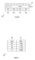
- An example mapping of these quantities is shown in the table 700 of Figure 7 .
- Each possible value of the two-bit d k (n) payload 620 is mapped to a different value 710 for ⁇ k (n).
- the ⁇ k (n) values are -3 dB, -1 dB, +1 dB, and +3 dB, but in other embodiments other ⁇ k (n) values could be used.
- the ⁇ k (n) value for the corresponding carrier is -3 dB
- the ⁇ k (n) value for the corresponding carrier is -1 dB
- the example table 800 shown in Figure 8 may be used to illustrate this method.
- the combined path loss and power control corrections for the previous reporting time (i.e., n - 1 ) are shown in the second column 820, and the combined path loss and power control corrections for the current reporting time (i.e., n ) are shown in the third column 830.
- the path loss has generally increased (e.g., perhaps the UA is now shadowed by a building), although by a different amount for each carrier.
- the fourth column 840 contains the delta change for each carrier from time n - 1 to time n .
- the fifth column 850 shows the delta value of each carrier relative to the reference carrier. These quantities may be obtained by subtracting the reference carrier's value in the fourth column 840 from each carrier's delta value in the fourth column 840. This essentially follows the equation defined above for ⁇ k (n). The values in this last column 850 may then be mapped to d k (n) for signaling purposes as shown in table 700 of Figure 7 .
- a mapped ⁇ k (n) value that is close to the derived ⁇ k (n) value can be used. For example, for values where an exact match does not occur in table 700 (such as 0 dB for carrier 4), the closest ⁇ k (n) from table 700 is selected.
- a UA transmits the PH of only a certain reporting carrier or of only certain reporting carriers.
- the UA transmits PH information only for a carrier or carriers for which a specific event trigger occurs or when that carrier's PUSCH is scheduled.
- Different dl-PathlossChange, periodicPNR-Timer, and / or prohibitPHR-Timer can be configured for each carrier or for a subset of carriers.
- PHs of all triggered carriers can be transmitted. For example, when the path loss difference is larger than a preconfigured threshold in carrier #1, UA would transmit the PH only for carrier #1. To indicate to the access node which reporting carriers' PHs are being transmitted, additional signaling, such as a bitmap, is included with a PH report. In some embodiments, if the allocated UL resources cannot accommodate the MAC control element of all PHs plus its subheader as a result of logical channel prioritization, then the UA can decide not to transmit all PHs or transmit PHs of a subset of carriers in the MAC control element to be accommodated in the allocated UL resources.
- the UA can select carriers based on the logical or physical carrier indexing. In one embodiment, the UA can select a carrier based on the priority of carrier. For example, the UA can transmit PH of the uplink anchor carrier or carrier transmitting the high QoS data.
- a MAC control element 900 includes a bitmap 910 with a length equal to the number of reporting carriers. In this case, there are five reporting carriers, so the bitmap 910 includes five bits.
- the bit in the k th position indicates whether or not the PH value of the k th carrier is included in the control element 900. For example, "1" may mean that the corresponding PH value is included, while “0” may mean that the PH value is not included.
- the first, fourth, and fifth bits of the bitmap 910 are set to "1", so PH values for the first, fourth, and fifth carriers are included in the control element 900.
- reporting triggers could determine whether the PH of a reporting carrier is included in the control element 900.
- an access node could specify that reporting carrier PHs are to be included only for the carrier having the highest PH or only for carriers having a PH larger than a specified threshold.
- the number of carriers to include and/or the threshold can be predefined or configured by higher-layer signaling.
- the UA indicates the number of reported PH values and a corresponding carrier index for each of the carriers transmitting a PH value.
- the UA transmits a consolidated power headroom report (i.e., PH information for multiple carriers contained within a single MAC control element) on only one of the reporting carriers.
- This carrier can be labeled as the signaling carrier.
- the first PH value in a reported list of PH values can be automatically associated with the signaling carrier. Additional PH values in the list are then indexed using two-bit values to indicate which carrier they are associated with, with a predetermined order being used to link index values with carriers (e.g., in ascending order of frequency).
- the first two bits 1010 of a MAC control element 1000 represent the total number of PH values included in the control element 1000, with the range of values that can be signaled being a function of the total number of aggregated carriers (e.g., a range of 2-5 when five carriers are aggregated, and a range of 1-4 when less than five carriers are aggregated).
- the remainder 1020 of the first octet includes the PH of the signaling carrier.
- Each subsequent octet includes a two-bit carrier index 1030 followed by a PH 1040 for the indexed carrier.
- the index 1030 indicates which of the other, non-signaling carriers has the PH value in the PH portion 1040 of the octet. For example, if there were four non-signaling carriers, a carrier index 1030 of "00" might refer to the first non-signaling carrier, a carrier index 1030 of "01" might refer to the second non-signaling carrier, and so on.
- a UA might report PH values for all carriers periodically. Meanwhile, in the event-triggered case, the UA might report only for the selected carriers in order to reduce the signaling overhead.
- the calculation used to obtain PH in an LTE-based environment is modified to be carrier-specific in an LTE-A-based environment.
- An example of such a modified PH equation for calculating the PH value for LTE-A is given below.
- PH k i P CMAX , k - 10 ⁇ log 10 M PUSCH , k i + M O_PUSCH , k j + ⁇ k j ⁇ PL k + ⁇ TF , k i + f k i
- the definition of each parameter is given in 3GPP TS 36.213, but parameter values are different on a per-carrier basis.
- k denotes the kth carrier to be reported.
- a UA may not have a current PUSCH allocation for a particular reporting carrier. Such a UA would not have the necessary scheduling information and therefore could not perform the PH calculation.
- the UA makes certain assumptions in this situation in order to calculate and report PH values for any non-scheduled carriers. One of three different techniques might be used.
- the UA copies the resource configuration for a scheduled carrier. At least one carrier must be scheduled in order for the UA to be able to transmit a PH report. Any non-scheduled reporting carriers can use the same scheduling configuration (i.e., the number of resource blocks and the transport block size), as given for a selected scheduled carrier, in order to calculate a PH value. Possible methods for selecting a scheduled carrier whose scheduling configuration would be "copied" could be to select the nearest carrier as measured by carrier frequency or to select the scheduled carrier with the lowest or highest carrier frequency.
- the configuration of the Sounding Reference Signal (SRS) transmission is used.
- the SRS is transmitted periodically from the UA and is used by the access node to detect the UA channel situation.
- the access node configures the UA to transmit SRS in each carrier.
- the number of resource blocks of the SRS transmission is semi-statically configured and ⁇ TF,k ( i ) is set to zero, so the UA is typically aware of these values. Since both the UA and access node know the SRS transmission parameters, the number of resource blocks of the SRS transmission can be used if a PUSCH transmission is not scheduled for a particular carrier.
- a reference configuration is predefined.
- Fixed reference values for the number of resource blocks and the transport block size can be predefined or configured by higher-layer signaling and then used in the calculation of a PH value for a non-scheduled carrier.
- the PUCCH-related PH may need to be transmitted to indicate that the transmit power used for the PUCCH-related PH can be the PH only for the PUCCH or can be a combined PUCCH and PUSCH PH. If the access node receives only the PUSCH PH, it may be difficult to exactly estimate the allowable PUSCH power when the PUSCH and PUCCH are transmitted simultaneously, because the sum of PUSCH and PUCCH power is limited not to exceed the maximum transmit power.
- the UA transmits the PUCCH-related PH in a MAC control element when PH reporting is triggered and a PUSCH resource is scheduled.
- the PUCCH-related PH is calculated by the UA based on the actual transmit power of the PUCCH.
- the calculated PUCCH-related PH is inserted in the MAC control element and transmitted to the access node.
- the UA cannot calculate the PH because the PUCCH transmit power is not defined when the PUCCH is not transmitted.
- One solution is to assume a reference configuration among different PUCCH formats when the UA transmits the PUCCH-related PH and the PUCCH is not transmitted.
- This reference configuration can be predefined in the specification or configured by higher layer signaling.
- the higher layer signaling could be UA-specific signaling or broadcast signaling.
- the reference configuration could be one of the PUCCH formats from 3rd Generation Partnership Project (3GPP) Technical Specification (TS) 36.211.
- the reference configuration could be PUCCH format 1A from TS 36.211.
- the PUCCH format requiring the most transmission power is used as the reference configuration.
- the UA estimates the transmission power needed to transmit the PUCCH assuming it were to transmit the PUCCH using the reference configuration. It then uses this estimated transmission power to calculate the PUCCH-related PH.
- PH i ( P CMAX - P 0 _PUCCH + PL + h n CQI n HARQ + ⁇ F_PUCCH F + g i if PUCCHis transmitted P CMAX - P 0 _PUCCH + PL + g i otherwise
- PH i ( P CMAX - P 0 _PUCCH + PL + h n CQI n HARQ + ⁇ F_PUCCH F + g i - 10 ⁇ log 10 M PUSCH i + P O_PUSCH j + ⁇ j ⁇ PL + ⁇ TF i + f i ) if PUCCHis transmitted P CMAX - P 0 _PUCCH + PL + g i - 10 ⁇ log 10 M PUSCH i + P O_PUSCH j + ⁇ j ⁇ PL + ⁇ TF i + f i ) otherwise
- the UA assumes the fixed value for the parameters which are variable depending on the transmitted PUCCH transmission.
- h ( n CQI , n HARQ ) and ⁇ F_PUCCH ( F ) are different for different PUCCH formats.
- the UA uses reference values for these parameters, where the reference value can be predefined in the specification or configured by higher layer signaling. For example, if the UA assumes both h ( n CQI , n HARQ ) and ⁇ F_PUCCH ( F ) as 0, the above equation can be used. Other non-zero values can also be used.
- Figure 11 illustrates an exemplary MAC control element wherein the PUSCH PH and PUCCH-related PH are transmitted in a single MAC control element.
- four reserved bits are included in octet 1
- six bits are used to represent the PUSCH PH
- six bits are used to represent the PUCCH-related PH.
- one MAC control element is used to represent the PUSCH PH and another MAC control element is used to represent the PUCCH-related PH.
- the allocated UL resources cannot accommodate the combined MAC control element (PUCCH-related PH + PUSCH PH) plus its subheader as a result of logical channel prioritization, then the UA only transmits one MAC control element containing the PUSCH PH.
- the access node configures whether PUCCH-related PH reporting should be performed using broadcast signaling or dedicated (UA-specific) signaling. For example, the access node can configure some UAs to report PUCCH-related PH and PUSCH PH. These two reports can be transmitted from the UA using a single MAC control element. The access node can configure other UAs to report only PUSCH PH. This one report can be transmitted from the UA using a single MAC control element. The configuration can be based on UA capability, scheduling algorithms, etc.
- a UA may be configured to report PUSCH PH for one or multiple carriers and PUCCH-related PH for one or multiple carriers.
- One or multiple MAC control elements can be used to report the required PH information.
- one of the factors included in the calculation of power headroom is the downlink path loss.
- the downlink path loss is the downlink path loss.
- the determination of which downlink component carrier is to be used for path loss derivation is based on a downlink component carrier that is linked to an uplink component carrier in the broadcast system information.
- the determination of which downlink component carrier is to be used for path loss derivation is based on a downlink component carrier that that has been designated for path loss derivation.
- PL k i P CMAX , k - 10 ⁇ log 10 M PUSCH , k i + M O_PUSCH , k j + ⁇ k j ⁇ PL k + ⁇ TF , k i + f k i
- PL is the downlink path loss estimate derived by the UA
- PL referenceSignalPower - higher layer filtered RSRP (Reference Signal Received Power), where referenceSignalPower is provided by higher layers and RSRP is measured in the UA and filtered with the higher layer filter configuration defined by higher layers.
- PL be derived from the DL CC on which the UA measures RSRP.
- a UA can be configured to receive multiple DL CCs, and it may be possible to refer to any DL CC for path loss derivation, although there is a cell-specific linkage between DL CC and UL CC for idle mode UAs, and this linkage is typically signaled in the system information. Therefore, it may be helpful to define which of the multiple DL CCs should be used for PL derivation.
- the DL CC may not always be activated.
- multiple DL CCs may be configured for a UA supporting carrier aggregation. These configured DL CCs can be activated or deactivated via MAC signaling. Actual downlink data is scheduled only to the activated DL CCs. This means that the UA may not need to receive PDCCH or PDSCH on the deactivated DL CCs. In this case, to save UA battery power, the UA could stop receiving all DL transmissions on the deactivated DL CCs.
- the UA If the UA is implemented in this way, it would also be desirable not to derive PL on a deactivated CC even though that DL CC has been designated for PL derivation (especially if RSRP measurement on a deactivated CC consumes UA processing power).
- One exception would be that the UA could measure RSRP on a deactivated CC if this measurement is explicitly configured by higher layer signaling.
- a different DL CC can be used other than the linked DL CC for PL derivation.
- an offset value can be signaled by the access node. The access node could generate this offset based on measurement reporting or a statistical model or field testing.
- the PL may not be correct in the actual environment, especially if the DL CC being referenced is located in a different frequency band from the UL CC and the UA is moving.
- DL PCC Downlink Primary Component Carrier
- one of the DL CCs is configured as the DL PCC, and the DL PCC is never deactivated.
- Paired DL CC This is a DL CC cell specifically linked to a UL CC in the broadcast system information.
- Another type can be referred to as the DL CC_pl.
- This is a DL CC used for PL derivation.
- Each UL CC could be configured to reference one DL CC_pl for PL derivation. With these definitions in place, two alternatives can be provided.
- the UA uses the paired DL CC for PL derivation if that paired DL CC is activated or configured for measurement. Since the paired DL CC for each UL CC is signaled in the system information, additional signaling to indicate DL CC_pl would not be required.
- the UA may still derive PL from the (deactivated) paired DL CC. In this case, the UA still measures RSRP on the paired DL CC.
- the UA may derive PL from another DL CC in the same band where the other DL CC is activated or where measurement has been configured.
- the UA derives PL from another DL CC provided by the access node.
- the reference carrier may be implicit, such as the DL PCC.
- the offset between DL CCs and PCC may need to be signaled. Since PL difference is likely to happen when PCC and DL CC are in different bands, the offset can be signaled if the corresponding DL CC is in a different band than PCC. Alternatively, the offset between frequency bands can be signaled.
- One of these approaches can be selected or all three approaches can be defined. When all approaches can be applicable, it may be preferable to prioritize using the first or second approach, considering the accuracy of PL derivation. In other words, if the paired DL CC is not activated and not configured for measurement, the UA may still derive PL from the paired DL CC or may derive PL from another DL CC in the same band where the DL CC is either activated or measurement is configured. Otherwise, the UA might use the offset (and the reference DL CC where the offset should be applied) provided by the access node.
- the access node can configure the UA to reference any DL CC for DL CC_pl.
- An offset may not be needed if the PL of DL CC_pl and the actual PL required for the UL CC are similar. This might happen if they are located in the same frequency band. Otherwise, the offset could be signaled.
- Two different UA operations might be used depending on whether the DL CC_pl is in the same frequency band as the UL CC or not. In the case where DL CC_pl is in the same frequency band as the UL CC, the UA could use the DL CC_pl for PL derivation if that DL CC_pl is activated or configured for measurement.
- the UA could apply the same approaches as described with regard to the first alternative.
- the UA may use another DL CC, e.g., the paired DL CC or DL CC in the same frequency band with the UL CC if this DL CC is activated or configured for measurement. Otherwise, the UA could derive the PL with DL CC_pl and an offset. This is because the PL derived by the paired DL CC or DL CC in the same frequency band might be more accurate than the PL derived by the DL CC_pl with an offset.
- the same PL derivation method could be applied to the uplink transmit power setting for uplink channels, e.g., PUSCH or PUCCH, as well as the PH value calculation in each UL CC.
- Figure 12 illustrates an embodiment of a method 1200 for reporting power headroom-related information for a plurality of aggregated carriers.
- power headroom-related information is reported for a number of the aggregated carriers that is less than or equal to the total number of aggregated carriers.
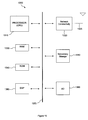
- FIG. 13 illustrates an example of a system 1300 that includes a processing component 1310 suitable for implementing one or more embodiments disclosed herein.
- the system 1300 might include network connectivity devices 1320, random access memory (RAM) 1330, read only memory (ROM) 1340, secondary storage 1350, and input/output (I/O) devices 1360.
- RAM random access memory
- ROM read only memory
- secondary storage 1350 secondary storage
- I/O input/output
- These components might communicate with one another via a bus 1370. In some cases, some of these components may not be present or may be combined in various combinations with one another or with other components not shown.
- DSP digital signal processor
- the processor 1310 executes instructions, codes, computer programs, or scripts that it might access from the network connectivity devices 1320, RAM 1330, ROM 1340, or secondary storage 1350 (which might include various disk-based systems such as hard disk, floppy disk, or optical disk). While only one CPU 1310 is shown, multiple processors may be present. Thus, while instructions may be discussed as being executed by a processor, the instructions may be executed simultaneously, serially, or otherwise by one or multiple processors.
- the processor 1310 may be implemented as one or more CPU chips.
- the network connectivity devices 1320 may take the form of modems, modem banks, Ethernet devices, universal serial bus (USB) interface devices, serial interfaces, token ring devices, fiber distributed data interface (FDDI) devices, wireless local area network (WLAN) devices, radio transceiver devices such as code division multiple access (CDMA) devices, global system for mobile communications (GSM) radio transceiver devices, worldwide interoperability for microwave access (WiMAX) devices, and/or other well-known devices for connecting to networks.
- These network connectivity devices 1320 may enable the processor 1310 to communicate with the Internet or one or more telecommunications networks or other networks from which the processor 1310 might receive information or to which the processor 1310 might output information.
- the network connectivity devices 1320 might also include one or more transceiver components 1325 capable of transmitting and/or receiving data wirelessly.
- the RAM 1330 might be used to store volatile data and perhaps to store instructions that are executed by the processor 1310.
- the ROM 1340 is a non-volatile memory device that typically has a smaller memory capacity than the memory capacity of the secondary storage 1350. ROM 1340 might be used to store instructions and perhaps data that are read during execution of the instructions. Access to both RAM 1330 and ROM 1340 is typically faster than to secondary storage 1350.
- the secondary storage 1350 is typically comprised of one or more disk drives or tape drives and might be used for non-volatile storage of data or as an over-flow data storage device if RAM 1330 is not large enough to hold all working data. Secondary storage 1350 may be used to store programs that are loaded into RAM 1330 when such programs are selected for execution.
- the I/O devices 1360 may include liquid crystal displays (LCDs), touch screen displays, keyboards, keypads, switches, dials, mice, track balls, voice recognizers, card readers, paper tape readers, printers, video monitors, or other well-known input/output devices.
- the transceiver 1325 might be considered to be a component of the I/O devices 1360 instead of or in addition to being a component of the network connectivity devices 1320.
- a method for reporting power headroom-related information for a plurality of aggregated carriers.
- the method includes reporting the power headroom-related information for a number of the aggregated carriers that is less than or equal to the total number of aggregated carriers.
- a user agent in another embodiment, includes a component configured such that the user agent transmits power headroom-related information for a number of aggregated carriers that is less than or equal to the total number of aggregated carriers in a plurality of aggregated carriers.
- an access node in a wireless telecommunications system includes a component configured such that the access node receives power headroom-related information for a number of aggregated carriers that is less than or equal to the total number of aggregated carriers in a plurality of aggregated carriers.
- a method for reporting power headroom-related information for a plurality of aggregated carriers.
- the method comprises reporting the power headroom-related information for a number of the aggregated carriers that is less than or equal to the total number of aggregated carriers, wherein the power headroom-related information is one of a power headroom for at least one of the aggregated carriers and a path loss for at least one of the aggregated carriers.
- the method or portions of the method may be carried out by a UA and/or an access node.
- a method for reporting power headroom for a plurality of aggregated carriers.
- the method comprises transmitting a power headroom value that is one of a power headroom for a reference carrier in the aggregation of carriers and a function of power headroom values for the aggregation of carriers.
- the method further comprises, for each of the remaining carriers in the aggregation of carriers, reporting a variation of the power headroom from the transmitted power headroom value.
- the method or portions of the method may be carried out by a UA and/or an access node.
- a method for determining which carrier among a plurality of aggregated carriers is to be used for derivation of a path loss.
- the method comprises basing the determination on at least one of a downlink component carrier that is linked to an uplink component carrier in broadcast system information and a downlink component carrier that has been designated for path loss derivation.
- the method or portions of the method may be carried out by a UA and/or an access node.
- 3GPP 3rd Generation Partnership Project
- TS Technical Specification
- 3GPP TS 36.213 3GPP TS 36.321
- TR 3GPP Technical Report
Claims (12)
- Procédé destiné à exploiter un agent utilisateur dans un réseau de communications sans fil configuré pour supporter une pluralité de porteuses agrégées, le procédé comprenant le fait :de recevoir, par un agent utilisateur, un ensemble de porteuses à partir du nombre total de porteuses agrégées pour lesquelles les informations liées à la marge de puissance doivent être rapportées, etde fournir, par l'agent utilisateur, un noeud d'accès avec des informations liées à la marge de puissance pour un nombre de porteuses agrégées qui est inférieur ou égal au nombre total de porteuses agrégées, pour lesquelles les informations liées à la marge de puissance doivent être rapportées.
- Procédé de la revendication 1, dans lequel le fait de fournir des informations liées à la marge de puissance est déclenché par l'un :d'un changement de l'affaiblissement de propagation d'une porteuse de rapport parmi l'agrégation de porteuses, plus grand qu'une quantité prédéfinie depuis un rapport de marge de puissance précédent ;d'un ajout d'une porteuse à l'agrégation de porteuses ; etd'une expiration d'un temporisateur qui commande les rapports de marge de puissance périodiques.
- Procédé de la revendication 1, dans lequel les informations liées à la marge de puissance sont transmises dans un élément de contrôle pour le contrôle d'accès au support 'MAC'.
- Procédé de la revendication 3, dans lequel les informations liées à la marge de puissance sont transmises sous forme d'un long format, le long format contenant les informations liées à la marge de puissance pour toutes les porteuses dans la pluralité de porteuses agrégées.
- Procédé de la revendication 3, dans lequel le nombre des porteuses agrégées est égal au nombre total de porteuses agrégées.
- Procédé selon la revendication 3, dans lequel une marge de puissance liée à un canal de commande de liaison montante physique 'PUCCH', est transmise dans l'élément de contrôle MAC lorsqu'un rapport de marge de puissance est déclenché et une ressource de canal partagé de liaison montante physique 'PUSCH' est programmée.
- Procédé de la revendication 6, dans lequel, lorsque le PUCCH est transmis dans la même sous-trame dans laquelle la marge de puissance liée au PUCCH est rapportée, la marge de puissance liée au PUCCH est calculée sur la base d'une puissance à l'émission réelle du PUCCH.
- Procédé de la revendication 6, dans lequel, lorsque le PUCCH n'est pas transmis lorsque la marge de puissance liée au PUCCH est rapportée, une configuration de référence est adoptée parmi une pluralité de formats PUCCH, la configuration de référence étant au moins l'une :d'une configuration prédéfinie dans une spécification ;d'une configuration configurée par une signalisation de couche supérieure spécifique à un équipement utilisateur ;d'une configuration configurée par une signalisation de couche supérieure de diffusion ; etd'une configuration dans un format PUCCH nécessitant la plus grande puissance de transmission.
- Procédé de la revendication 3, dans lequel la transmission des informations liées à une marge de puissance comporte l'une :d'une marge de puissance liée au PUSCH ;d'une marge de puissance liée au PUSCH et d'une marge de puissance liée au PUCCH ; etd'une marge de puissance liée au PUSCH sur au moins une porteuse et une marge de puissance liée au PUCCH sur au moins une autre porteuse.
- Agent utilisateur 'UA' adapté pour recevoir un ensemble de porteuses parmi un nombre total de porteuses agrégées pour lesquelles les informations liées à la marge de puissance doivent être rapportées, et comprenant :un composant configuré de sorte que le UA fournisse un noeud d'accès avec des informations liées à la marge de puissance pour un nombre de porteuses agrégées qui est inférieur ou égal au nombre total de porteuses agrégées pour lesquelles les informations liées à la marge de puissance doivent être rapportées.
- Noeud d'accès dans un système de télécommunications sans fil, le noeud d'accès étant configuré pour fournir un agent utilisateur avec un ensemble de porteuses à partir d'un nombre total de porteuses agrégées pour lesquelles les informations liées à la marge de puissance doivent être rapportées, et comprenant :un composant configuré de sorte que le noeud d'accès reçoive, à partir d'un agent utilisateur, des informations liées à la marge de puissance pour un nombre de porteuses agrégées qui est inférieur ou égal au nombre total de porteuses agrégées pour lesquelles les informations liées à la marge de puissance doivent être rapportées.
- Support lisible par ordinateur contenant des instructions qui, lorsqu'elles sont exécutées par un processeur, mettent en oeuvre les étapes de l'une des revendications du procédé ci-dessus.
Applications Claiming Priority (4)
| Application Number | Priority Date | Filing Date | Title |
|---|---|---|---|
| US18065209P | 2009-05-22 | 2009-05-22 | |
| US30392010P | 2010-02-12 | 2010-02-12 | |
| US32021110P | 2010-04-01 | 2010-04-01 | |
| PCT/US2010/035844 WO2010135697A2 (fr) | 2009-05-22 | 2010-05-21 | Compte rendu de marge de puissance pour agrégation de porteuse |
Publications (2)
| Publication Number | Publication Date |
|---|---|
| EP2433447A2 EP2433447A2 (fr) | 2012-03-28 |
| EP2433447B1 true EP2433447B1 (fr) | 2013-03-13 |
Family
ID=42562803
Family Applications (9)
| Application Number | Title | Priority Date | Filing Date |
|---|---|---|---|
| EP10730881A Active EP2433447B1 (fr) | 2009-05-22 | 2010-05-21 | Compte rendu de marge de puissance pour agrégation de porteuse |
| EP10730883A Withdrawn EP2433449A2 (fr) | 2009-05-22 | 2010-05-21 | Système et procédé permettant de transmettre des informations de marge de puissance pour des porteuses agglomérées |
| EP20151845.3A Active EP3657867B1 (fr) | 2009-05-22 | 2010-05-21 | Compte-rendu de marge de puissance pour des porteuses agglomérées |
| EP15172887.0A Active EP2945440B1 (fr) | 2009-05-22 | 2010-05-21 | Compte-rendu de marge de puissance pour des porteuses agglomérées |
| EP18182273.5A Active EP3404968B1 (fr) | 2009-05-22 | 2010-05-21 | Compte rendu de marge de puissance pour porteuses agglomérées |
| EP21215914.9A Active EP3989651B1 (fr) | 2009-05-22 | 2010-05-21 | Compte rendu de marge de puissance pour des porteuses agrégées |
| EP13151125.5A Active EP2582189B1 (fr) | 2009-05-22 | 2010-05-21 | Compte rendu de marge de puissance pour agrégation de porteuse |
| EP10730882A Active EP2433448B1 (fr) | 2009-05-22 | 2010-05-21 | Compte rendu de marge de puissance pour porteuses agglomérées |
| EP17158544.1A Active EP3240335B1 (fr) | 2009-05-22 | 2010-05-21 | Compte-rendu de marge de puissance pour des porteuses agglomérées |
Family Applications After (8)
| Application Number | Title | Priority Date | Filing Date |
|---|---|---|---|
| EP10730883A Withdrawn EP2433449A2 (fr) | 2009-05-22 | 2010-05-21 | Système et procédé permettant de transmettre des informations de marge de puissance pour des porteuses agglomérées |
| EP20151845.3A Active EP3657867B1 (fr) | 2009-05-22 | 2010-05-21 | Compte-rendu de marge de puissance pour des porteuses agglomérées |
| EP15172887.0A Active EP2945440B1 (fr) | 2009-05-22 | 2010-05-21 | Compte-rendu de marge de puissance pour des porteuses agglomérées |
| EP18182273.5A Active EP3404968B1 (fr) | 2009-05-22 | 2010-05-21 | Compte rendu de marge de puissance pour porteuses agglomérées |
| EP21215914.9A Active EP3989651B1 (fr) | 2009-05-22 | 2010-05-21 | Compte rendu de marge de puissance pour des porteuses agrégées |
| EP13151125.5A Active EP2582189B1 (fr) | 2009-05-22 | 2010-05-21 | Compte rendu de marge de puissance pour agrégation de porteuse |
| EP10730882A Active EP2433448B1 (fr) | 2009-05-22 | 2010-05-21 | Compte rendu de marge de puissance pour porteuses agglomérées |
| EP17158544.1A Active EP3240335B1 (fr) | 2009-05-22 | 2010-05-21 | Compte-rendu de marge de puissance pour des porteuses agglomérées |
Country Status (6)
| Country | Link |
|---|---|
| US (10) | US8855061B2 (fr) |
| EP (9) | EP2433447B1 (fr) |
| CA (6) | CA3147011A1 (fr) |
| ES (3) | ES2785991T3 (fr) |
| HK (3) | HK1168962A1 (fr) |
| WO (3) | WO2010135698A2 (fr) |
Families Citing this family (120)
| Publication number | Priority date | Publication date | Assignee | Title |
|---|---|---|---|---|
| US8095515B2 (en) * | 2008-03-19 | 2012-01-10 | Semmle Limited | Approximating relation sizes using field dependencies |
| KR101722810B1 (ko) | 2008-12-03 | 2017-04-05 | 인터디지탈 패튼 홀딩스, 인크 | 캐리어 집적에 대한 업링크 파워 헤드룸 보고 |
| US8848594B2 (en) | 2008-12-10 | 2014-09-30 | Blackberry Limited | Method and apparatus for discovery of relay nodes |
| US8040904B2 (en) * | 2008-12-17 | 2011-10-18 | Research In Motion Limited | System and method for autonomous combining |
| US8402334B2 (en) | 2008-12-17 | 2013-03-19 | Research In Motion Limited | System and method for hybrid automatic repeat request (HARQ) functionality in a relay node |
| US8355388B2 (en) * | 2008-12-17 | 2013-01-15 | Research In Motion Limited | System and method for initial access to relays |
| US8311061B2 (en) | 2008-12-17 | 2012-11-13 | Research In Motion Limited | System and method for multi-user multiplexing |
| US8335466B2 (en) | 2008-12-19 | 2012-12-18 | Research In Motion Limited | System and method for resource allocation |
| US8265128B2 (en) | 2008-12-19 | 2012-09-11 | Research In Motion Limited | Multiple-input multiple-output (MIMO) with relay nodes |
| US8446856B2 (en) | 2008-12-19 | 2013-05-21 | Research In Motion Limited | System and method for relay node selection |
| WO2010091425A2 (fr) | 2009-02-09 | 2010-08-12 | Interdigital Patent Holdings, Inc. | Appareil et procédé de commande de puissance de liaison montante pour une unité de réception/émission sans fil utilisant des porteuses multiples |
| WO2010135698A2 (fr) | 2009-05-22 | 2010-11-25 | Research In Motion Limited | Compte rendu de marge de puissance pour porteuses agglomérées |
| JP5360207B2 (ja) * | 2009-06-03 | 2013-12-04 | 日本電気株式会社 | 基地局装置、エッジユーザ推定方法及びプログラム |
| CN101932019B (zh) * | 2009-06-19 | 2015-06-03 | 中兴通讯股份有限公司 | 一种实现上报缓冲区状态报告的方法、终端及网络系统 |
| CN101932045B (zh) * | 2009-06-24 | 2014-11-05 | 中兴通讯股份有限公司 | 载波聚合中测量结果的上报方法及用户设备 |
| WO2010150552A1 (fr) | 2009-06-26 | 2010-12-29 | パナソニック株式会社 | Appareils de radiocommunication et procédé de radiocommunication |
| US8687581B2 (en) * | 2009-07-09 | 2014-04-01 | Lg Electronics Inc. | Method and device for sending and receiving control data on a wireless communications system |
| US8498273B2 (en) * | 2009-08-06 | 2013-07-30 | Telefonaktiebolaget L M Ericsson (Publ) | Management of uplink resources in multi-carrier CDMA system |
| KR101498349B1 (ko) * | 2009-08-14 | 2015-03-03 | 닛본 덴끼 가부시끼가이샤 | 반송파 집합에 대한 다운링크 제어 구조를 검출하는 방법 |
| US8559325B2 (en) * | 2009-09-15 | 2013-10-15 | Qualcomm Incorporated | Systems and methods for over the air load indicator for wireless scheduling |
| EP2484074B1 (fr) * | 2009-09-30 | 2014-06-25 | Telefonaktiebolaget L M Ericsson (PUBL) | Reconfiguration de porteuses de composant actives dans des systèmes sans fil à porteuses multiples |
| JP5555326B2 (ja) | 2009-10-01 | 2014-07-23 | インターデイジタル パテント ホールディングス インコーポレイテッド | 電力制御の方法および装置 |
| US8768397B2 (en) | 2009-10-02 | 2014-07-01 | Sharp Kabushiki Kaisha | Transmission power control on a wireless communication device for a plurality of regulated bands or component carriers |
| US9059749B2 (en) | 2009-10-02 | 2015-06-16 | Sharp Kabushiki Kaisha | Antenna port mode and transmission mode transitions |
| US20110080838A1 (en) * | 2009-10-02 | 2011-04-07 | Telefonaktiebolaget Lm Ericsson (Publ) | Methods and Arrangements in a Mobile Telecommunication Network |
| US20110080885A1 (en) * | 2009-10-05 | 2011-04-07 | Electronics And Telecommunications Research Institute | Apparatus and method for management of extension carrier in base station |
| KR101734948B1 (ko) * | 2009-10-09 | 2017-05-12 | 삼성전자주식회사 | 파워 헤드룸 보고, 자원 할당 및 전력 제어 방법 |
| JP5020300B2 (ja) * | 2009-10-28 | 2012-09-05 | シャープ株式会社 | 無線通信システム、移動局装置、基地局装置、無線通信方法および移動局装置の制御プログラム |
| WO2011053056A2 (fr) * | 2009-10-29 | 2011-05-05 | 엘지전자 주식회사 | Appareil et procédé d'émission-réception d'informations de commande de puissance de transmission en amont dans un système de communication à porteuses multiples |
| KR101785997B1 (ko) * | 2009-10-30 | 2017-10-17 | 주식회사 골드피크이노베이션즈 | 무선통신 시스템에서 요소 반송파 집합 정보 전송방법 및 그 기지국, 단말의 수신방법 |
| EP2317815A1 (fr) | 2009-11-02 | 2011-05-04 | Panasonic Corporation | Rapport de limite de puissance dans un système de communication utilisant une agrégation de support |
| US9025541B2 (en) * | 2009-11-04 | 2015-05-05 | Lg Electronics Inc. | Terminal device for transmitting a power headroom report in a multi-carrier communication system, and method for same |
| US8902817B2 (en) * | 2009-12-15 | 2014-12-02 | Nokia Corporation | Method, mobile station, base station and computer program product to control the activation of a wireless carrier |
| CN102612127B (zh) * | 2009-12-30 | 2014-04-02 | 华为技术有限公司 | 一种功率控制方法和装置 |
| KR101366335B1 (ko) | 2010-04-01 | 2014-03-12 | 엘지전자 주식회사 | 무선 접속 시스템에서 상향링크 전력 제어 방법 및 장치 |
| TWI555419B (zh) | 2010-04-02 | 2016-10-21 | 聯發科技股份有限公司 | 管理多成分載波、緩存器狀態報告以及功率餘裕回報方法 |
| US8537767B2 (en) * | 2010-04-06 | 2013-09-17 | Sunplus Technology Co., Ltd | Method for performing power headroom reporting procedure and PHR MAC control element |
| EP2375832A3 (fr) * | 2010-04-07 | 2011-11-30 | HTC Corporation | Procédé d'allocation de puissance de retransmissions |
| JP4812887B1 (ja) * | 2010-04-30 | 2011-11-09 | 株式会社エヌ・ティ・ティ・ドコモ | 移動通信方法及び移動局 |
| RU2564529C2 (ru) * | 2010-05-04 | 2015-10-10 | Телефонактиеболагет Лм Эрикссон (Пабл) | Сообщение запаса мощности для агрегации несущих |
| US8867440B2 (en) * | 2010-05-28 | 2014-10-21 | Qualcomm Incorporated | Power headroom reporting for multicarrier LTE systems |
| EP2582075A4 (fr) * | 2010-06-09 | 2015-10-14 | Lg Electronics Inc | Procédé et dispositif pour transmettre/recevoir des informations d'état de canal dans un système de communication sans fil qui supporte des porteuses multiples |
| WO2011159123A2 (fr) * | 2010-06-17 | 2011-12-22 | Pantech Co., Ltd. | Appareil et procédé d'émission d'informations de puissance dans un système à composantes porteuses multiples |
| KR20110137983A (ko) * | 2010-06-18 | 2011-12-26 | 주식회사 팬택 | 다중 요소 반송파 시스템에서 잉여전력 정보의 전송장치 및 방법 |
| KR101852814B1 (ko) | 2010-06-18 | 2018-04-27 | 엘지전자 주식회사 | 무선 통신 시스템에서 단말이 잔여전력 정보를 송신하는 방법 및 이를 위한 장치 |
| PL2908580T3 (pl) * | 2010-06-18 | 2017-11-30 | Telefonaktiebolaget Lm Ericsson (Publ) | Sposoby dostarczania raportów o marginesie mocy uporządkowanych według indeksów nośnych składowych oraz powiązane stacje bazowe |
| WO2011160275A1 (fr) * | 2010-06-21 | 2011-12-29 | 上海贝尔股份有限公司 | Procédé destiné à rapporter une marge de puissance dans un réseau d'agrégation de porteuses |
| WO2011161014A1 (fr) | 2010-06-21 | 2011-12-29 | Nokia Siemens Networks Oy | Regroupement de porteuses avec signalement de la marge de puissance |
| CN105101292B (zh) * | 2010-06-22 | 2018-03-09 | 华为技术有限公司 | 一种功率余量报告的上报方法和用户设备 |
| EP2400803B1 (fr) | 2010-06-28 | 2019-12-11 | Samsung Electronics Co., Ltd. | Procédé et appareil pour rapporter la puissance de transmission maximale dans une communication sans fil |
| KR101740366B1 (ko) * | 2010-06-28 | 2017-05-29 | 삼성전자주식회사 | 이동 통신 시스템에서 역방향 최대 전송 전력을 보고하는 방법 및 장치 |
| KR20120001535A (ko) * | 2010-06-29 | 2012-01-04 | 주식회사 팬택 | 다중 요소 반송파 시스템에서 잉여전력 보고장치 및 방법 |
| CN102316569B (zh) * | 2010-06-29 | 2015-05-20 | 中兴通讯股份有限公司 | 一种用于载波聚合场景下的phr上报方法和系统 |
| US9526077B2 (en) | 2010-08-10 | 2016-12-20 | Samsung Electronics Co., Ltd. | Method and apparatus for reporting power headroom information in mobile communication system supporting carrier aggregation |
| US9344977B2 (en) * | 2010-08-10 | 2016-05-17 | Samsung Electronics Co., Ltd. | Method and apparatus for reporting power headroom information in mobile communication system supporting carrier aggregation |
| US8954106B2 (en) * | 2010-08-10 | 2015-02-10 | Samsung Electronics Co., Ltd. | Method and apparatus for configuring power headroom information in mobile communication system supporting carrier aggregation |
| CN102378239B (zh) * | 2010-08-11 | 2015-11-25 | 电信科学技术研究院 | 功率余量的上报、获取方法和装置 |
| EP2418895B1 (fr) * | 2010-08-12 | 2015-01-07 | HTC Corporation | Procédé de gestion de rapports de marge de puissance de la liaison montante avec agrégation de porteuses et dispositif de communication correspondant |
| CN102104905B (zh) * | 2010-08-13 | 2014-02-05 | 电信科学技术研究院 | 载波聚合场景下的功率余量上报方法和设备 |
| KR101276853B1 (ko) * | 2010-08-17 | 2013-06-18 | 엘지전자 주식회사 | 멀티캐리어를 지원하는 통신 시스템에서 파워 헤드룸 리포트를 전송하는 방법 및 장치 |
| US9173178B2 (en) * | 2010-09-21 | 2015-10-27 | Broadcom Corporation | Method and system for power headroom reporting in the presence of multiple transmit antennas |
| CN102118786B (zh) * | 2010-09-29 | 2015-07-22 | 电信科学技术研究院 | 一种载波聚合系统下phr的处理方法和设备 |
| US20130121203A1 (en) * | 2010-09-30 | 2013-05-16 | Lg Electronics Inc. | Apparatus and Method of Reporting Power Headroom in Wireless Communication System |
| WO2012060612A2 (fr) * | 2010-11-03 | 2012-05-10 | Pantech Co., Ltd. | Appareil et procédé de transmission d'informations de puissance concernant une porteuse composante dans un système à multiples porteuses composantes |
| US8687727B2 (en) * | 2010-11-05 | 2014-04-01 | Intel Corporation | Coordinated multi-point transmission using interference feedback |
| KR101762610B1 (ko) | 2010-11-05 | 2017-08-04 | 삼성전자주식회사 | 이동 통신 시스템에서 역방향 스케줄링 및 그를 위한 정보 전송 방법 및 장치 |
| US9144038B2 (en) * | 2010-11-05 | 2015-09-22 | Samsung Electronics Co., Ltd. | Method and apparatus for calculating power headroom in carrier aggregation mobile communication system |
| WO2012059249A1 (fr) * | 2010-11-05 | 2012-05-10 | Telefonaktiebolaget L M Ericsson (Publ) | Élément de commande de marge de puissance, procédé de communication d'informations de puissance à partir d'un équipement utilisateur, procédé de traitement d'informations de puissance reçues, ainsi qu'équipement utilisateur et station de base correspondants |
| CN102469058B (zh) * | 2010-11-12 | 2016-02-10 | 中兴通讯股份有限公司 | 一种用于载波聚合场景的载波最大功率的上报方法和装置 |
| WO2012071705A1 (fr) * | 2010-11-30 | 2012-06-07 | 富士通株式会社 | Procédé et équipement utilisateur permettant de déclencher un rapport de marge de puissance |
| JP4969682B2 (ja) * | 2010-12-09 | 2012-07-04 | シャープ株式会社 | 移動局装置、通信システム、通信方法および集積回路 |
| CN102595613B (zh) * | 2011-01-06 | 2017-02-08 | 中兴通讯股份有限公司 | 载波聚合场景下上报小区特定的最大功率的方法及装置 |
| EP2676475B1 (fr) | 2011-02-15 | 2022-04-06 | Samsung Electronics Co., Ltd. | Rapport de marge de puissance |
| KR102073027B1 (ko) | 2011-04-05 | 2020-02-04 | 삼성전자 주식회사 | 반송파 집적 기술을 사용하는 무선통신시스템에서 복수 개의 타임 정렬 타이머 운용 방법 및 장치 |
| CN102647800B (zh) * | 2011-02-16 | 2016-09-14 | 华为技术有限公司 | 载波聚合中的功率余量处理方法及用户设备、基站 |
| KR101995293B1 (ko) | 2011-02-21 | 2019-07-02 | 삼성전자 주식회사 | 반송파 집적 기술을 사용하는 시분할 무선통신시스템에서 부차반송파의 활성화 또는 비활성화 방법 및 장치 |
| WO2012115421A2 (fr) | 2011-02-21 | 2012-08-30 | Samsung Electronics Co., Ltd. | Procédé de signalement efficace de la puissance d'émission d'un équipement utilisateur et appareil associé |
| CN102123437B (zh) * | 2011-03-03 | 2016-02-17 | 电信科学技术研究院 | 功率余量上报和调度子帧的方法、系统及设备 |
| US9681401B2 (en) * | 2011-03-17 | 2017-06-13 | Google Technology Holdings LLC | Enhanced power headroom reporting in wireless communication networks |
| US8849215B2 (en) * | 2011-03-30 | 2014-09-30 | Amazon Technologies, Inc. | Reducing rate of detection cycles and measurement cycles in a discontinuous reception (DRX) mode |
| KR101948801B1 (ko) | 2011-04-11 | 2019-02-18 | 삼성전자주식회사 | Mbms 지원 사용자 장치의 데이터 수신 방법 및 장치 |
| US10075969B2 (en) * | 2011-04-25 | 2018-09-11 | Texas Instruments Incorporated | Medium access control schedulers for wireless communication |
| KR101835387B1 (ko) * | 2011-04-29 | 2018-03-08 | 삼성전자주식회사 | 단말기 및 그 단말기에서 자원 스케줄링 방법 |
| US9185666B2 (en) * | 2011-05-06 | 2015-11-10 | Qualcomm Incorporated | Power headroom reporting related to power management maximum power reduction |
| EP3965317A1 (fr) | 2011-05-10 | 2022-03-09 | Samsung Electronics Co., Ltd. | Procédé et appareil permettant d'appliquer un temporisateur d'alignement temporel dans un système de communication sans fil à l'aide d'une technique d'agrégation de porteuses |
| CN102843776B (zh) * | 2011-06-20 | 2017-03-22 | 中兴通讯股份有限公司 | 多载波终端调度方法、信道质量信息发送方法及系统 |
| WO2013022295A2 (fr) * | 2011-08-09 | 2013-02-14 | 엘지전자 주식회사 | Procédé de fonctionnement dans de multiples cellules, et dispositif sans fil utilisant celui-ci |
| EP2742748A4 (fr) * | 2011-08-12 | 2015-08-26 | Intel Corp | Système et procédé de régulation de puissance sur la liaison montante dans un système de communication sans fil |
| US9521632B2 (en) | 2011-08-15 | 2016-12-13 | Google Technology Holdings LLC | Power allocation for overlapping transmission when multiple timing advances are used |
| WO2013046965A1 (fr) * | 2011-09-28 | 2013-04-04 | シャープ株式会社 | Dispositif de station mobile, système et procédé de communication et circuit intégré |
| EP2761780A1 (fr) | 2011-09-30 | 2014-08-06 | Interdigital Patent Holdings, Inc. | Transmission multipoint dans un système de communication sans fil |
| US9642114B2 (en) * | 2011-11-04 | 2017-05-02 | Intel Corporation | Path-loss estimation for uplink power control in a carrier aggregation environment |
| US9282568B2 (en) * | 2011-11-18 | 2016-03-08 | Futurewei Technologies, Inc. | Method and system for dynamic, joint assignment of power and scheduling of users for wireless systems |
| US9363768B2 (en) | 2012-07-09 | 2016-06-07 | Dali Systems Co. Ltd. | Self-optimizing distributed antenna system using soft frequency reuse |
| CN105191445B (zh) | 2013-04-03 | 2018-11-27 | 交互数字专利控股公司 | 一种干扰测量方法、装置及基站 |
| CN105359595B (zh) | 2013-05-02 | 2019-10-25 | 三星电子株式会社 | 在无线通信系统中用于控制上行链路功率的方法和装置 |
| WO2014203033A1 (fr) | 2013-06-18 | 2014-12-24 | Freescale Semiconductor, Inc. | Dispositif et procédé de commande d'agrégation de porteuses |
| EP2861025B8 (fr) * | 2013-10-09 | 2023-05-17 | Innovative Sonic Corporation | Procédé et appareil de compte rendu de marge de puissance dans un système de communication sans fil |
| US10361833B2 (en) * | 2013-12-11 | 2019-07-23 | Innovative Sonic Corporation | Method and apparatus for improving device to device (D2D) communication in a wireless communication system |
| US9480029B2 (en) | 2014-01-06 | 2016-10-25 | Intel IP Corporation | Power headroom reporting with dual connectivity |
| EP3378257B1 (fr) * | 2015-11-17 | 2020-04-22 | Telefonaktiebolaget LM Ericsson (PUBL) | Procédé, dispositif de communication sans fil et noeud radio pour l'attribution de puissance en liaison descendante lors du déploiement d'un système à bande étroite dans un système à large bande |
| EP3855812B1 (fr) * | 2016-08-08 | 2022-10-05 | LG Electronics Inc. | Procédé et dispositif de notification de csi |
| KR102606781B1 (ko) * | 2016-09-02 | 2023-11-27 | 삼성전자 주식회사 | 무선 통신 시스템에서 효율적인 데이터 송수신 방법 및 장치 |
| US10582397B2 (en) * | 2016-11-09 | 2020-03-03 | Qualcomm Incorporated | Beam refinement reference signal transmissions during control symbol |
| US9769773B1 (en) * | 2017-01-09 | 2017-09-19 | Sprint Spectrum L.P. | Controlling per-carrier maximum transmit power of a device served on a plurality of carriers |
| CN110402607B (zh) | 2017-03-16 | 2021-04-27 | 北京小米移动软件有限公司 | 截断缓冲区状态报告 |
| US10856174B2 (en) | 2017-03-16 | 2020-12-01 | Ofinno, Llc | Buffer status report control |
| US10863380B2 (en) | 2017-03-16 | 2020-12-08 | Ofinno, Llc | Buffer status reporting procedure in a wireless device and wireless network |
| EP3711382A1 (fr) | 2017-11-16 | 2020-09-23 | Telefonaktiebolaget LM Ericsson (Publ) | Utilisation de marge de puissance pour porteuses de liaison montante supplémentaires |
| CN109803363B (zh) * | 2017-11-17 | 2022-11-08 | 华为技术有限公司 | 通信方法、通信装置和系统 |
| EP3739998B1 (fr) * | 2018-01-12 | 2024-03-06 | Ntt Docomo, Inc. | Terminal utilisateur, et procédé de communication sans fil |
| KR102257411B1 (ko) | 2018-05-10 | 2021-05-28 | 아서스테크 컴퓨터 인코포레이션 | 무선 통신 시스템에서 다중 경로손실 레퍼런스를 위한 전력 헤드룸 리포트를 트리거링하는 방법 및 장치 |
| US10660077B2 (en) | 2018-08-09 | 2020-05-19 | Lenovo (Singapore) Pte Ltd | Uplink transmission power allocation |
| US10681644B2 (en) * | 2018-08-21 | 2020-06-09 | Qualcomm Incorporated | Reporting actual uplink transmission power |
| CN112567880A (zh) | 2019-07-25 | 2021-03-26 | 谷歌有限责任公司 | 用户设备协调集重新分组 |
| US11350439B2 (en) * | 2019-08-13 | 2022-05-31 | Google Llc | User-equipment-coordination-set control aggregation |
| WO2021054964A1 (fr) | 2019-09-19 | 2021-03-25 | Google Llc | Participation sélective d'un ensemble de coordination d'équipements utilisateur |
| US11812314B2 (en) * | 2020-05-20 | 2023-11-07 | Qualcomm Incorporated | Dynamic switching between carrier aggregation and multi-connectivity |
| AU2021444749A1 (en) * | 2021-05-11 | 2023-09-14 | Zte Corporation | Systems and methods for reporting power-related information |
| US20230038515A1 (en) * | 2021-08-05 | 2023-02-09 | Qualcomm Incorporated | Techniques for aperiodic discontinuous reception mode communications |
Family Cites Families (31)
| Publication number | Priority date | Publication date | Assignee | Title |
|---|---|---|---|---|
| US20060013182A1 (en) * | 2004-07-19 | 2006-01-19 | Telefonaktiebolaget Lm Ericsson | Selective multicarrier CDMA network |
| WO2007023555A1 (fr) | 2005-08-25 | 2007-03-01 | Fujitsu Limited | Terminal mobile et dispositif station base |
| EP1999982B1 (fr) * | 2006-03-20 | 2018-08-29 | BlackBerry Limited | Procédé et système de réutilisation des fréquences des canaux à demi-débit |
| US8867453B2 (en) | 2006-04-24 | 2014-10-21 | Samsung Electronics Co., Ltd. | System and method for subcarrier allocation signaling in a multicarrier wireless network |
| KR101197521B1 (ko) | 2006-04-24 | 2012-11-09 | 삼성전자주식회사 | 공통 제어 채널을 이용하는 이동통신 시스템에서 자원 할당정보를 비트맵을 통해 송수신하는 방법 및 장치 |
| US8019373B2 (en) * | 2006-06-16 | 2011-09-13 | Samsung Electronics Co., Ltd | System and method for controlling power in a communication system |
| US7917166B2 (en) * | 2006-06-16 | 2011-03-29 | Samsung Electronics Co., Ltd. | System and method for controlling power in a communication system |
| JP4818942B2 (ja) * | 2007-01-19 | 2011-11-16 | 株式会社エヌ・ティ・ティ・ドコモ | 基地局装置及び通信制御方法 |
| CN101675700B (zh) * | 2007-03-01 | 2013-04-03 | 株式会社Ntt都科摩 | 基站装置以及通信控制方法 |
| CA2691230C (fr) * | 2007-06-20 | 2015-11-24 | Nokia Siemens Networks Oy | Procede de rapport de marge de puissance |
| CN101340711B (zh) | 2007-07-06 | 2012-05-23 | 中兴通讯股份有限公司 | 多载波增强上行接入系统的调度信息上报方法 |
| US8867378B2 (en) * | 2007-10-05 | 2014-10-21 | Qualcomm Incorporated | Triggering multi-carrier requests |
| KR101459147B1 (ko) * | 2008-02-04 | 2014-11-10 | 엘지전자 주식회사 | 무선통신 시스템에서 전송 파워 제어 명령 전송 방법 |
| US8218661B2 (en) * | 2008-03-18 | 2012-07-10 | Mitsubishi Electric Research Laboratories, Inc. | OFDMA based medium access control and frame structure design for industrial applications |
| US8279818B2 (en) * | 2008-10-31 | 2012-10-02 | Htc Corporation | Methods of packet element transmission in wireless communications system |
| KR101722810B1 (ko) * | 2008-12-03 | 2017-04-05 | 인터디지탈 패튼 홀딩스, 인크 | 캐리어 집적에 대한 업링크 파워 헤드룸 보고 |
| US8565170B2 (en) * | 2009-01-14 | 2013-10-22 | Qualcomm Incorporated | Method and apparatus for scheduling data transmission on multiple carriers |
| US8547860B2 (en) * | 2009-02-09 | 2013-10-01 | Qualcomm Incorporated | Uplink carrier allocation |
| US8422387B2 (en) * | 2009-03-16 | 2013-04-16 | Htc Corporation | Method and apparatus of handling uplink information under carrier aggregation in a wireless communication system |
| US9270430B2 (en) * | 2009-03-23 | 2016-02-23 | Innovative Sonic Limited | Method and apparatus for power headroom reporting |
| US20100272091A1 (en) * | 2009-04-27 | 2010-10-28 | Motorola, Inc. | Uplink Scheduling Supoort in Multi-Carrier Wireless Communication Systems |
| US8437798B2 (en) * | 2009-04-27 | 2013-05-07 | Motorola Mobility Llc | Uplink scheduling support in multi-carrier wireless communication systems |
| US8995358B2 (en) * | 2009-04-30 | 2015-03-31 | Qualcomm Incorporated | False detection reduction during multi-carrier operation |
| WO2010135698A2 (fr) * | 2009-05-22 | 2010-11-25 | Research In Motion Limited | Compte rendu de marge de puissance pour porteuses agglomérées |
| CN105245312B (zh) | 2009-06-19 | 2019-05-07 | 交互数字专利控股公司 | 在lte-a中用信号发送上行链路控制信息的方法及单元 |
| US8249091B2 (en) | 2009-10-21 | 2012-08-21 | Samsung Electronics Co., Ltd | Power headroom reporting method and device for wireless communication system |
| EP2317815A1 (fr) | 2009-11-02 | 2011-05-04 | Panasonic Corporation | Rapport de limite de puissance dans un système de communication utilisant une agrégation de support |
| TWI555419B (zh) | 2010-04-02 | 2016-10-21 | 聯發科技股份有限公司 | 管理多成分載波、緩存器狀態報告以及功率餘裕回報方法 |
| WO2011161014A1 (fr) * | 2010-06-21 | 2011-12-29 | Nokia Siemens Networks Oy | Regroupement de porteuses avec signalement de la marge de puissance |
| CN102104905B (zh) * | 2010-08-13 | 2014-02-05 | 电信科学技术研究院 | 载波聚合场景下的功率余量上报方法和设备 |
| EP2622915B1 (fr) * | 2010-09-30 | 2018-04-25 | Panasonic Intellectual Property Corporation of America | Configuration d'avance de synchronisation pour de multiples porteuses composantes de liaison montante |
-
2010
- 2010-05-21 WO PCT/US2010/035845 patent/WO2010135698A2/fr active Application Filing
- 2010-05-21 US US12/785,325 patent/US8855061B2/en active Active
- 2010-05-21 CA CA3147011A patent/CA3147011A1/fr active Pending
- 2010-05-21 CA CA3054129A patent/CA3054129C/fr active Active
- 2010-05-21 US US12/785,323 patent/US8351359B2/en active Active
- 2010-05-21 EP EP10730881A patent/EP2433447B1/fr active Active
- 2010-05-21 CA CA2763195A patent/CA2763195C/fr active Active
- 2010-05-21 EP EP10730883A patent/EP2433449A2/fr not_active Withdrawn
- 2010-05-21 CA CA2972529A patent/CA2972529C/fr active Active
- 2010-05-21 WO PCT/US2010/035846 patent/WO2010135699A2/fr active Application Filing
- 2010-05-21 EP EP20151845.3A patent/EP3657867B1/fr active Active
- 2010-05-21 EP EP15172887.0A patent/EP2945440B1/fr active Active
- 2010-05-21 CA CA2763048A patent/CA2763048C/fr active Active
- 2010-05-21 ES ES18182273T patent/ES2785991T3/es active Active
- 2010-05-21 ES ES20151845T patent/ES2911431T3/es active Active
- 2010-05-21 WO PCT/US2010/035844 patent/WO2010135697A2/fr active Application Filing
- 2010-05-21 CA CA2763448A patent/CA2763448C/fr active Active
- 2010-05-21 US US12/785,320 patent/US8626225B2/en active Active
- 2010-05-21 EP EP18182273.5A patent/EP3404968B1/fr active Active
- 2010-05-21 EP EP21215914.9A patent/EP3989651B1/fr active Active
- 2010-05-21 ES ES17158544.1T patent/ES2694674T3/es active Active
- 2010-05-21 EP EP13151125.5A patent/EP2582189B1/fr active Active
- 2010-05-21 EP EP10730882A patent/EP2433448B1/fr active Active
- 2010-05-21 EP EP17158544.1A patent/EP3240335B1/fr active Active
-
2012
- 2012-09-27 HK HK12109542.0A patent/HK1168962A1/xx unknown
- 2012-09-27 HK HK12109533.1A patent/HK1168961A1/xx unknown
- 2012-11-29 US US13/689,020 patent/US8744341B2/en active Active
-
2013
- 2013-10-17 HK HK13111702.1A patent/HK1184621A1/xx unknown
-
2014
- 2014-04-24 US US14/261,206 patent/US9252935B2/en active Active
-
2016
- 2016-01-29 US US15/011,089 patent/US9936467B2/en active Active
-
2018
- 2018-02-21 US US15/901,663 patent/US10548098B2/en active Active
-
2020
- 2020-01-07 US US16/736,250 patent/US10959192B2/en active Active
-
2021
- 2021-03-19 US US17/207,217 patent/US11576132B2/en active Active
-
2023
- 2023-01-20 US US18/157,487 patent/US11937190B2/en active Active
Also Published As
Similar Documents
| Publication | Publication Date | Title |
|---|---|---|
| US11937190B2 (en) | Reporting power headroom for aggregated carriers |
Legal Events
| Date | Code | Title | Description |
|---|---|---|---|
| PUAI | Public reference made under article 153(3) epc to a published international application that has entered the european phase |
Free format text: ORIGINAL CODE: 0009012 |
|
| 17P | Request for examination filed |
Effective date: 20111222 |
|
| AK | Designated contracting states |
Kind code of ref document: A2 Designated state(s): AL AT BE BG CH CY CZ DE DK EE ES FI FR GB GR HR HU IE IS IT LI LT LU LV MC MK MT NL NO PL PT RO SE SI SK SM TR |
|
| DAX | Request for extension of the european patent (deleted) | ||
| REG | Reference to a national code |
Ref country code: DE Ref legal event code: R079 Ref document number: 602010005488 Country of ref document: DE Free format text: PREVIOUS MAIN CLASS: H04W0052340000 Ipc: H04L0005000000 |
|
| GRAP | Despatch of communication of intention to grant a patent |
Free format text: ORIGINAL CODE: EPIDOSNIGR1 |
|
| RIC1 | Information provided on ipc code assigned before grant |
Ipc: H04W 72/12 20090101AFI20120831BHEP Ipc: H04W 52/36 20090101ALI20120831BHEP |
|
| RIC1 | Information provided on ipc code assigned before grant |
Ipc: H04W 52/14 20090101ALI20120920BHEP Ipc: H04W 52/34 20090101ALI20120920BHEP Ipc: H04L 5/00 20060101AFI20120920BHEP Ipc: H04W 72/12 20090101ALI20120920BHEP Ipc: H04W 52/36 20090101ALI20120920BHEP |
|
| REG | Reference to a national code |
Ref country code: HK Ref legal event code: DE Ref document number: 1168961 Country of ref document: HK |
|
| GRAS | Grant fee paid |
Free format text: ORIGINAL CODE: EPIDOSNIGR3 |
|
| GRAA | (expected) grant |
Free format text: ORIGINAL CODE: 0009210 |
|
| AK | Designated contracting states |
Kind code of ref document: B1 Designated state(s): AL AT BE BG CH CY CZ DE DK EE ES FI FR GB GR HR HU IE IS IT LI LT LU LV MC MK MT NL NO PL PT RO SE SI SK SM TR |
|
| REG | Reference to a national code |
Ref country code: GB Ref legal event code: FG4D |
|
| REG | Reference to a national code |
Ref country code: AT Ref legal event code: REF Ref document number: 601340 Country of ref document: AT Kind code of ref document: T Effective date: 20130315 Ref country code: CH Ref legal event code: EP |
|
| REG | Reference to a national code |
Ref country code: IE Ref legal event code: FG4D |
|
| REG | Reference to a national code |
Ref country code: DE Ref legal event code: R096 Ref document number: 602010005488 Country of ref document: DE Effective date: 20130508 |
|
| PG25 | Lapsed in a contracting state [announced via postgrant information from national office to epo] |
Ref country code: LT Free format text: LAPSE BECAUSE OF FAILURE TO SUBMIT A TRANSLATION OF THE DESCRIPTION OR TO PAY THE FEE WITHIN THE PRESCRIBED TIME-LIMIT Effective date: 20130313 Ref country code: NO Free format text: LAPSE BECAUSE OF FAILURE TO SUBMIT A TRANSLATION OF THE DESCRIPTION OR TO PAY THE FEE WITHIN THE PRESCRIBED TIME-LIMIT Effective date: 20130613 Ref country code: SE Free format text: LAPSE BECAUSE OF FAILURE TO SUBMIT A TRANSLATION OF THE DESCRIPTION OR TO PAY THE FEE WITHIN THE PRESCRIBED TIME-LIMIT Effective date: 20130313 Ref country code: ES Free format text: LAPSE BECAUSE OF FAILURE TO SUBMIT A TRANSLATION OF THE DESCRIPTION OR TO PAY THE FEE WITHIN THE PRESCRIBED TIME-LIMIT Effective date: 20130624 Ref country code: BG Free format text: LAPSE BECAUSE OF FAILURE TO SUBMIT A TRANSLATION OF THE DESCRIPTION OR TO PAY THE FEE WITHIN THE PRESCRIBED TIME-LIMIT Effective date: 20130613 |
|
| REG | Reference to a national code |
Ref country code: NL Ref legal event code: T3 |
|
| REG | Reference to a national code |
Ref country code: CH Ref legal event code: PFA Owner name: BLACKBERRY LIMITED, CA Free format text: FORMER OWNER: RESEARCH IN MOTION LIMITED, CA Ref country code: AT Ref legal event code: MK05 Ref document number: 601340 Country of ref document: AT Kind code of ref document: T Effective date: 20130313 |
|
| REG | Reference to a national code |
Ref country code: LT Ref legal event code: MG4D |
|
| PG25 | Lapsed in a contracting state [announced via postgrant information from national office to epo] |
Ref country code: SI Free format text: LAPSE BECAUSE OF FAILURE TO SUBMIT A TRANSLATION OF THE DESCRIPTION OR TO PAY THE FEE WITHIN THE PRESCRIBED TIME-LIMIT Effective date: 20130313 Ref country code: GR Free format text: LAPSE BECAUSE OF FAILURE TO SUBMIT A TRANSLATION OF THE DESCRIPTION OR TO PAY THE FEE WITHIN THE PRESCRIBED TIME-LIMIT Effective date: 20130614 Ref country code: FI Free format text: LAPSE BECAUSE OF FAILURE TO SUBMIT A TRANSLATION OF THE DESCRIPTION OR TO PAY THE FEE WITHIN THE PRESCRIBED TIME-LIMIT Effective date: 20130313 Ref country code: LV Free format text: LAPSE BECAUSE OF FAILURE TO SUBMIT A TRANSLATION OF THE DESCRIPTION OR TO PAY THE FEE WITHIN THE PRESCRIBED TIME-LIMIT Effective date: 20130313 |
|
| RAP2 | Party data changed (patent owner data changed or rights of a patent transferred) |
Owner name: BLACKBERRY LIMITED |
|
| REG | Reference to a national code |
Ref country code: HK Ref legal event code: GR Ref document number: 1168961 Country of ref document: HK |
|
| PG25 | Lapsed in a contracting state [announced via postgrant information from national office to epo] |
Ref country code: BE Free format text: LAPSE BECAUSE OF FAILURE TO SUBMIT A TRANSLATION OF THE DESCRIPTION OR TO PAY THE FEE WITHIN THE PRESCRIBED TIME-LIMIT Effective date: 20130313 Ref country code: HR Free format text: LAPSE BECAUSE OF FAILURE TO SUBMIT A TRANSLATION OF THE DESCRIPTION OR TO PAY THE FEE WITHIN THE PRESCRIBED TIME-LIMIT Effective date: 20130313 |
|
| PG25 | Lapsed in a contracting state [announced via postgrant information from national office to epo] |
Ref country code: IS Free format text: LAPSE BECAUSE OF FAILURE TO SUBMIT A TRANSLATION OF THE DESCRIPTION OR TO PAY THE FEE WITHIN THE PRESCRIBED TIME-LIMIT Effective date: 20130713 Ref country code: AT Free format text: LAPSE BECAUSE OF FAILURE TO SUBMIT A TRANSLATION OF THE DESCRIPTION OR TO PAY THE FEE WITHIN THE PRESCRIBED TIME-LIMIT Effective date: 20130313 Ref country code: EE Free format text: LAPSE BECAUSE OF FAILURE TO SUBMIT A TRANSLATION OF THE DESCRIPTION OR TO PAY THE FEE WITHIN THE PRESCRIBED TIME-LIMIT Effective date: 20130313 Ref country code: CZ Free format text: LAPSE BECAUSE OF FAILURE TO SUBMIT A TRANSLATION OF THE DESCRIPTION OR TO PAY THE FEE WITHIN THE PRESCRIBED TIME-LIMIT Effective date: 20130313 Ref country code: SK Free format text: LAPSE BECAUSE OF FAILURE TO SUBMIT A TRANSLATION OF THE DESCRIPTION OR TO PAY THE FEE WITHIN THE PRESCRIBED TIME-LIMIT Effective date: 20130313 Ref country code: RO Free format text: LAPSE BECAUSE OF FAILURE TO SUBMIT A TRANSLATION OF THE DESCRIPTION OR TO PAY THE FEE WITHIN THE PRESCRIBED TIME-LIMIT Effective date: 20130313 Ref country code: PT Free format text: LAPSE BECAUSE OF FAILURE TO SUBMIT A TRANSLATION OF THE DESCRIPTION OR TO PAY THE FEE WITHIN THE PRESCRIBED TIME-LIMIT Effective date: 20130715 |
|
| REG | Reference to a national code |
Ref country code: CH Ref legal event code: PCOW Free format text: NEW ADDRESS: 2200 UNIVERSITY AVENUE EAST, WATERLOO, ON N2K 0A7 (CA) |
|
| RAP2 | Party data changed (patent owner data changed or rights of a patent transferred) |
Owner name: BLACKBERRY LIMITED |
|
| PG25 | Lapsed in a contracting state [announced via postgrant information from national office to epo] |
Ref country code: PL Free format text: LAPSE BECAUSE OF FAILURE TO SUBMIT A TRANSLATION OF THE DESCRIPTION OR TO PAY THE FEE WITHIN THE PRESCRIBED TIME-LIMIT Effective date: 20130313 |
|
| PG25 | Lapsed in a contracting state [announced via postgrant information from national office to epo] |
Ref country code: MC Free format text: LAPSE BECAUSE OF FAILURE TO SUBMIT A TRANSLATION OF THE DESCRIPTION OR TO PAY THE FEE WITHIN THE PRESCRIBED TIME-LIMIT Effective date: 20130313 |
|
| PLBE | No opposition filed within time limit |
Free format text: ORIGINAL CODE: 0009261 |
|
| STAA | Information on the status of an ep patent application or granted ep patent |
Free format text: STATUS: NO OPPOSITION FILED WITHIN TIME LIMIT |
|
| PG25 | Lapsed in a contracting state [announced via postgrant information from national office to epo] |
Ref country code: DK Free format text: LAPSE BECAUSE OF FAILURE TO SUBMIT A TRANSLATION OF THE DESCRIPTION OR TO PAY THE FEE WITHIN THE PRESCRIBED TIME-LIMIT Effective date: 20130313 |
|
| 26N | No opposition filed |
Effective date: 20131216 |
|
| REG | Reference to a national code |
Ref country code: IE Ref legal event code: MM4A |
|
| PG25 | Lapsed in a contracting state [announced via postgrant information from national office to epo] |
Ref country code: IT Free format text: LAPSE BECAUSE OF FAILURE TO SUBMIT A TRANSLATION OF THE DESCRIPTION OR TO PAY THE FEE WITHIN THE PRESCRIBED TIME-LIMIT Effective date: 20130313 |
|
| REG | Reference to a national code |
Ref country code: DE Ref legal event code: R097 Ref document number: 602010005488 Country of ref document: DE Effective date: 20131216 |
|
| PG25 | Lapsed in a contracting state [announced via postgrant information from national office to epo] |
Ref country code: IE Free format text: LAPSE BECAUSE OF NON-PAYMENT OF DUE FEES Effective date: 20130521 |
|
| REG | Reference to a national code |
Ref country code: DE Ref legal event code: R082 Ref document number: 602010005488 Country of ref document: DE Representative=s name: MERH-IP MATIAS ERNY REICHL HOFFMANN, DE |
|
| REG | Reference to a national code |
Ref country code: DE Ref legal event code: R082 Ref document number: 602010005488 Country of ref document: DE Representative=s name: MERH-IP MATIAS ERNY REICHL HOFFMANN, DE Effective date: 20140926 Ref country code: DE Ref legal event code: R081 Ref document number: 602010005488 Country of ref document: DE Owner name: BLACKBERRY LIMITED, WATERLOO, CA Free format text: FORMER OWNER: RESEARCH IN MOTION LIMITED, WATERLOO, ONTARIO, CA Effective date: 20140926 Ref country code: DE Ref legal event code: R082 Ref document number: 602010005488 Country of ref document: DE Representative=s name: MERH-IP MATIAS ERNY REICHL HOFFMANN PATENTANWA, DE Effective date: 20140926 |
|
| REG | Reference to a national code |
Ref country code: CH Ref legal event code: PL |
|
| PG25 | Lapsed in a contracting state [announced via postgrant information from national office to epo] |
Ref country code: CH Free format text: LAPSE BECAUSE OF NON-PAYMENT OF DUE FEES Effective date: 20140531 Ref country code: LI Free format text: LAPSE BECAUSE OF NON-PAYMENT OF DUE FEES Effective date: 20140531 |
|
| PG25 | Lapsed in a contracting state [announced via postgrant information from national office to epo] |
Ref country code: MT Free format text: LAPSE BECAUSE OF FAILURE TO SUBMIT A TRANSLATION OF THE DESCRIPTION OR TO PAY THE FEE WITHIN THE PRESCRIBED TIME-LIMIT Effective date: 20130313 |
|
| PG25 | Lapsed in a contracting state [announced via postgrant information from national office to epo] |
Ref country code: SM Free format text: LAPSE BECAUSE OF FAILURE TO SUBMIT A TRANSLATION OF THE DESCRIPTION OR TO PAY THE FEE WITHIN THE PRESCRIBED TIME-LIMIT Effective date: 20130313 |
|
| PG25 | Lapsed in a contracting state [announced via postgrant information from national office to epo] |
Ref country code: TR Free format text: LAPSE BECAUSE OF FAILURE TO SUBMIT A TRANSLATION OF THE DESCRIPTION OR TO PAY THE FEE WITHIN THE PRESCRIBED TIME-LIMIT Effective date: 20130313 Ref country code: CY Free format text: LAPSE BECAUSE OF FAILURE TO SUBMIT A TRANSLATION OF THE DESCRIPTION OR TO PAY THE FEE WITHIN THE PRESCRIBED TIME-LIMIT Effective date: 20130313 |
|
| PG25 | Lapsed in a contracting state [announced via postgrant information from national office to epo] |
Ref country code: MK Free format text: LAPSE BECAUSE OF FAILURE TO SUBMIT A TRANSLATION OF THE DESCRIPTION OR TO PAY THE FEE WITHIN THE PRESCRIBED TIME-LIMIT Effective date: 20130313 Ref country code: HU Free format text: LAPSE BECAUSE OF FAILURE TO SUBMIT A TRANSLATION OF THE DESCRIPTION OR TO PAY THE FEE WITHIN THE PRESCRIBED TIME-LIMIT; INVALID AB INITIO Effective date: 20100521 Ref country code: LU Free format text: LAPSE BECAUSE OF NON-PAYMENT OF DUE FEES Effective date: 20130521 |
|
| REG | Reference to a national code |
Ref country code: FR Ref legal event code: PLFP Year of fee payment: 7 |
|
| REG | Reference to a national code |
Ref country code: FR Ref legal event code: PLFP Year of fee payment: 8 |
|
| REG | Reference to a national code |
Ref country code: FR Ref legal event code: PLFP Year of fee payment: 9 |
|
| PG25 | Lapsed in a contracting state [announced via postgrant information from national office to epo] |
Ref country code: AL Free format text: LAPSE BECAUSE OF FAILURE TO SUBMIT A TRANSLATION OF THE DESCRIPTION OR TO PAY THE FEE WITHIN THE PRESCRIBED TIME-LIMIT Effective date: 20130313 |
|
| P01 | Opt-out of the competence of the unified patent court (upc) registered |
Effective date: 20230518 |
|
| PGFP | Annual fee paid to national office [announced via postgrant information from national office to epo] |
Ref country code: NL Payment date: 20230526 Year of fee payment: 14 Ref country code: FR Payment date: 20230525 Year of fee payment: 14 Ref country code: DE Payment date: 20230530 Year of fee payment: 14 |
|
| PGFP | Annual fee paid to national office [announced via postgrant information from national office to epo] |
Ref country code: GB Payment date: 20230529 Year of fee payment: 14 |