EP2432291B1 - Wireless communication terminal and communication method - Google Patents
Wireless communication terminal and communication method Download PDFInfo
- Publication number
- EP2432291B1 EP2432291B1 EP10774746.1A EP10774746A EP2432291B1 EP 2432291 B1 EP2432291 B1 EP 2432291B1 EP 10774746 A EP10774746 A EP 10774746A EP 2432291 B1 EP2432291 B1 EP 2432291B1
- Authority
- EP
- European Patent Office
- Prior art keywords
- cqi
- subframe
- enb
- channel
- backhaul
- Prior art date
- Legal status (The legal status is an assumption and is not a legal conclusion. Google has not performed a legal analysis and makes no representation as to the accuracy of the status listed.)
- Active
Links
Images


Classifications
-
- H—ELECTRICITY
- H04—ELECTRIC COMMUNICATION TECHNIQUE
- H04W—WIRELESS COMMUNICATION NETWORKS
- H04W24/00—Supervisory, monitoring or testing arrangements
-
- H—ELECTRICITY
- H04—ELECTRIC COMMUNICATION TECHNIQUE
- H04B—TRANSMISSION
- H04B7/00—Radio transmission systems, i.e. using radiation field
- H04B7/24—Radio transmission systems, i.e. using radiation field for communication between two or more posts
- H04B7/26—Radio transmission systems, i.e. using radiation field for communication between two or more posts at least one of which is mobile
- H04B7/2603—Arrangements for wireless physical layer control
- H04B7/2606—Arrangements for base station coverage control, e.g. by using relays in tunnels
-
- H—ELECTRICITY
- H04—ELECTRIC COMMUNICATION TECHNIQUE
- H04L—TRANSMISSION OF DIGITAL INFORMATION, e.g. TELEGRAPHIC COMMUNICATION
- H04L1/00—Arrangements for detecting or preventing errors in the information received
- H04L1/0001—Systems modifying transmission characteristics according to link quality, e.g. power backoff
- H04L1/0023—Systems modifying transmission characteristics according to link quality, e.g. power backoff characterised by the signalling
- H04L1/0026—Transmission of channel quality indication
-
- H—ELECTRICITY
- H04—ELECTRIC COMMUNICATION TECHNIQUE
- H04L—TRANSMISSION OF DIGITAL INFORMATION, e.g. TELEGRAPHIC COMMUNICATION
- H04L1/00—Arrangements for detecting or preventing errors in the information received
- H04L1/20—Arrangements for detecting or preventing errors in the information received using signal quality detector
-
- H—ELECTRICITY
- H04—ELECTRIC COMMUNICATION TECHNIQUE
- H04L—TRANSMISSION OF DIGITAL INFORMATION, e.g. TELEGRAPHIC COMMUNICATION
- H04L12/00—Data switching networks
- H04L12/02—Details
- H04L12/16—Arrangements for providing special services to substations
- H04L12/18—Arrangements for providing special services to substations for broadcast or conference, e.g. multicast
- H04L12/189—Arrangements for providing special services to substations for broadcast or conference, e.g. multicast in combination with wireless systems
-
- H—ELECTRICITY
- H04—ELECTRIC COMMUNICATION TECHNIQUE
- H04L—TRANSMISSION OF DIGITAL INFORMATION, e.g. TELEGRAPHIC COMMUNICATION
- H04L5/00—Arrangements affording multiple use of the transmission path
- H04L5/003—Arrangements for allocating sub-channels of the transmission path
- H04L5/0053—Allocation of signalling, i.e. of overhead other than pilot signals
- H04L5/0057—Physical resource allocation for CQI
-
- H—ELECTRICITY
- H04—ELECTRIC COMMUNICATION TECHNIQUE
- H04W—WIRELESS COMMUNICATION NETWORKS
- H04W24/00—Supervisory, monitoring or testing arrangements
- H04W24/10—Scheduling measurement reports ; Arrangements for measurement reports
-
- H—ELECTRICITY
- H04—ELECTRIC COMMUNICATION TECHNIQUE
- H04L—TRANSMISSION OF DIGITAL INFORMATION, e.g. TELEGRAPHIC COMMUNICATION
- H04L27/00—Modulated-carrier systems
- H04L27/26—Systems using multi-frequency codes
- H04L27/28—Systems using multi-frequency codes with simultaneous transmission of different frequencies each representing one code element
-
- H—ELECTRICITY
- H04—ELECTRIC COMMUNICATION TECHNIQUE
- H04W—WIRELESS COMMUNICATION NETWORKS
- H04W24/00—Supervisory, monitoring or testing arrangements
- H04W24/02—Arrangements for optimising operational condition
-
- H—ELECTRICITY
- H04—ELECTRIC COMMUNICATION TECHNIQUE
- H04W—WIRELESS COMMUNICATION NETWORKS
- H04W84/00—Network topologies
- H04W84/02—Hierarchically pre-organised networks, e.g. paging networks, cellular networks, WLAN [Wireless Local Area Network] or WLL [Wireless Local Loop]
- H04W84/04—Large scale networks; Deep hierarchical networks
- H04W84/042—Public Land Mobile systems, e.g. cellular systems
- H04W84/047—Public Land Mobile systems, e.g. cellular systems using dedicated repeater stations
Definitions
- the present invention relates to a wireless communication terminal and a communication method for transmitting and receiving data to and from a base station.
- LTE-Advanced Long Term Evolution-Advanced
- LTE-A Long Term Evolution-Advanced
- Non-patent Literature 1 in LTE-A, a relay technology of relaying radio signals by using a relay node is being studied with the goals of coverage expansion and capacity improvement.
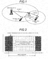
- FIG. 20 is a diagram showing a wireless communication system that relays radio signals by using the relay technology.
- eNB represents a base station
- RN represents a relay node
- UE represents a wireless communication terminal.
- UE1 represents a wireless communication terminal connected to eNB
- UE2 represents a wireless communication terminal connected to RN.
- RN has an individual cell ID as in eNB, and thereby, when viewed from UE, RN can be regarded as one cell like eNB.
- eNB is connected to a network by wired communication
- RN is connected to eNB by wireless communication.
- a communication channel connecting between RN and eNB is called a backhaul channel.
- a communication channel connecting between eNB or RN and UE is called an access channel.
- RN On the downlink channel, for example as shown in FIG. 20 , RN receives signals from eNB on the backhaul channel (an arrow A in the figure), and transmits the signals to UE2 on the access channel of RN (an arrow B in the figure).
- the backhaul channel and the access channel are allocated in the same frequency bandwidth, if RN performs transmission and reception at the same time, an interference due to feedback occurs. For this reason, RN cannot perform transmission and reception at the same time. Consequently, in LTE-A, a relay method is being studied in which the backhaul channel and the access channel of RN are allocated while being divided by the time domain (in units of subframes).
- FIG. 21 is a diagram showing the subframe structure on the downlink channel in the relay method.
- Reference designations [n, n+1, ...] in the figure represent subframe numbers, and boxes in the figure represent subframes on the downlink channel.
- transmission subframes of eNB crosshatched parts in the figure
- reception subframes of UE1 blank parts in the figure
- transmission subframes of RN rightward hatched parts in the figure
- reception subframes of UE2 leftward hatched parts in the figure.
- signals are transmitted from eNB in all the subframes [n, n+1, ..., n+6].
- UE1 is capable of performing reception in all the subframes.
- signals are transmitted in the subframes except for the subframe numbers [n+2, n+6].
- the arrows (thin lines) of FIG. 21 are transmitted in the subframes except for the subframe numbers [n+2, n+6].
- UE2 is capable of receiving signals in the subframes except for the subframe numbers [n+2, n+6].
- RN receives signals from eNB in the subframes of the subframe numbers [n+2, n+6]. That is, at RN, the subframes of the subframe numbers [n+2, n+6] serve as the backhaul channel, and the other subframes serve as the access channel of RN.
- RN transmits no signal from eNB in the subframes [n+2, n+6] where RN serves as the backhaul
- a problem arises in that a measurement operation to measure the quality of RN does not function at an LTE wireless communication terminal that does not know the presence of RN.
- MBSFN Multicast/Broadcast over Single Frequency Network
- the MBSFN subframe is a subframe prepared to realize an MBMS (Multimedia Broadcast and Multicast Service) service in the future.
- the MBSFN subframe is designed to transmit cell-specific control information at the first two symbols and transmit signals for the MBMS in the domains of the third and subsequent symbols. Consequently, LTE wireless communication terminals are capable of performing measurement by using the first two symbols in the MBSFN subframe.
- MBMS Multimedia Broadcast and Multicast Service
- the MBSFN subframe can be spuriously used in RN cells. That is, in the RN cell, at the first two symbols of the MBSFN subframe, the control information specific to the RN cell is transmitted, and in the domains of the third and subsequent symbols, signals from eNB are received without the data for the MBMS being transmitted. Consequently, in RN cells, the MBSFN subframe can be used as the reception subframe on the backhaul channel.
- the MBSFN subframe spuriously used in the RN cell as mentioned above will be called "MBSFN subframe that RN uses as the backhaul".
- eNB positively allocates UE where SIR improves in the subframes [n+2, n+6]. so that the user throughput at UE improves and this improves the throughput of the whole cells. Therefore, to improve the throughput of the whole cells, it is necessary for eNB to know the channel quality at UE.
- MBSFN subframes in order to separate the backhaul channel and the access channel of a relay node is known from the publication POTEVIO, " L1 Relay backward compatibility analysis", by Potevio et al. (3GPP DRAFT; R1-091411 L1 RELAY BACKWARD COMPATIBILITY ANALYSIS, 3RD GENERATION PARTNERSHIP PROJECT (3GPP), MOBILE COMPETENCE CENTRE ; 650, ROUTE DES LUCIOLES ; F-06921 SOPHIA-ANTIPOLIS CEDEX ; FRANCE, (20090317), no. Seoul, Korea; 20090317 ).
- This publication does not provide a solution for notifying a terminal controlled by a base station of the position of the MBSFN subframe that is used as the backhaul of a relay node in a neighboring cell.
- the CQI (Channel Quality Indicator) is the quality of the reception channel when viewed from the receiving side.
- the CQI is fed back from the receiving side to the transmitting side, and according to the fed-back CQI, the transmitting side selects the modulation method and the coding rate of the signal to be transmitted to the receiving side.
- An object of the present invention is to provide a wireless communication terminal and a communication method capable of accurately measuring the channel quality of the own cell in a condition where there is no interference from a neighbor cell.
- the channel quality of the own cell under a condition where there is no interference from a neighbor cell can be accurately measured.
- FIG. 1 is a diagram showing a wireless communication system that relays radio signals by using the relay technology in an embodiment of the present invention.
- eNB represents a base station 100
- RN represents a relay node 200
- UE1 represent a wireless communication terminal 300A
- UE2 represents a wireless communication terminal 300B.
- the wireless communication terminal 300A (UE1) is a wireless communication terminal connected to the base station 100
- the wireless communication terminal 300B (UE2) is a wireless communication terminal connected to the relay node 200 (RN).
- the wireless communication terminal 300A (UE1) is a wireless communication terminal (UE) under the control of the base station 100.
- the relay node 200 (RN) is a relay node connected to the base station 100.
- the relay node 200 (RN) has an individual cell ID being studied in LTE-A. Therefore, the relay node 200 (RN) adjacent to the wireless communication terminal 300A can be regarded as a neighbor cell when viewed from the wireless communication terminal 300A.
- the base station 100 will be referred to as eNB; the relay node 200, as RN; the wireless communication terminal 300A (UE1), as UE1; and the wireless communication terminal 300B, as UE2.
- RN receives signals from eNB on the backhaul channel (the arrow C in the figure), and transmits signals to UE2 on the access channel of RN (the arrow D in the figure).
- the relay method is such that the backhaul channel and the access channel are allocated in the same frequency bandwidth and the backhaul channel and the access channel of RN are allocated while being divided by the time domain (in units of subframes).
- UE1 under the control of eNB measures the CQI related to the channel (the channel of the own cell) from eNB to UE1 by using a signal in a predetermined domain in the "MBSFN subframe that RN uses as the backhaul".
- the "MBSFN subframe that RN uses as the backhaul" means an MBSFN subframe where in the RN cell, the control information specific to the RN cell is transmitted at the first two symbols of the MBSFN subframe and signals from eNB are received without the data for the MBMS being transmitted in the domains of the third and subsequent symbols.
- the amount of interference with the signals transmitted from eNB changes according to the presence or absence of signals from RN. For this reason, the reception SIR of the signals transmitted from eNB improves in the domains where no signal is transmitted from RN.
- the "MBSFN subframe that RN uses as the backhaul" is used, from the viewpoint of the subframe and from the viewpoint of the symbol, the domains where no signal is transmitted from RN can be identified.
- UE1 under the control of eNB can identify the domains where no signal is transmitted from RN, by the "MBSFN subframe that RN uses as the backhaul".
- the MBSFN subframe that RN uses as the backhaul changes in units of subframes.
- the MBSFN subframe is allocated to a predetermined position, and can be individually set for each cell.
- the position of allocation of the MBSFN subframe which is notified to UE by eNB or RN as system information in the SIB2 (System Information Block 2), is not instantaneously changed unlike the user allocation but is changed with a comparatively long period. For this reason, even when RN uses the MBSFN subframe as the backhaul, the position of the MBSFN subframe is individually set for each cell (RN). That is, if the MBSFN subframe used as the backhaul of the neighbor RN is identified, even UE1 under the control of eNB can identify that the subframe is a subframe where there is little interference from RN.
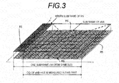
- FIG. 2 is a diagram showing the "MBSFN subframe that RN uses as the backhaul”.
- RN transmits signals such as cell-specific control information, and at the third and subsequent symbols, RN makes switching from transmission to reception and receives signals from eNB.
- the MBSFN subframe shown in FIG. 2 When viewed from UE1 under the control of eNB, in the MBSFN subframe shown in FIG. 2 , although the first two symbols appear to be interference, there is no interference in the domains of the third and subsequent symbols. That is, the amount of interference changes between in the domains of the first two symbols and in the domains of the third and subsequent symbols. Therefore, if the "MBSFN subframe that RN uses as the backhaul" is identified with respect to the neighbor RN, even UE1 under the control of eNB can identify a symbol where there is little interference from RN in the MBSFN subframe.
- LTE since LTE is based on the premise that neighbor cells are not synchronized with each other, there are cases where the timing of subframes is off between neighbor cells. For this reason, even if there is a subframe not performing transmission in the neighbor cell, it appears to be a part with interference and a part without interference for the subframe of the own cell. Moreover, to identify the symbol positions of the signals of the neighbor cell, it is necessary to take subframe synchronization with the neighbor cell. However, between eNB and RN connected to eNB, it is necessary that the subframe of the backhaul transmitted from eNB and the "MBSFN subframe that RN uses as the backhaul" be synchronized with each other.
- the subframe of the backhaul transmitted from eNB and the "MBSFN subframe that RN uses as the backhaul" be synchronized with each other at least in units of subframes.
- UE1 connected to eNB can be said to be substantially in synchronism in units of subframes although there is a delay time to the extent of approximately a propagation delay time. Consequently, the subframe of eNB which is the "MBSFN subframe that RN uses as the backhaul" is an MBSFN subframe that RN uses as the backhaul over the entire subframe.
- eNB notifies UE1 under its own control of the position of the "MBSFN subframe that RN uses as the backhaul", and in the "MBSFN subframe that RN uses as the backhaul", UE1 under the control of eNB measures the CQI related to the channel (the channel of the own cell) from eNB to UE1 by using the signals in the domains of the third and subsequent symbols.
- eNB notifies UE1 under its own control of the position of the "MBSFN subframe that RN uses as the backhaul" at RN connected to eNB.
- the notification method includes a method in which notification is provided by using system information (system information block), control information in a higher-level layer or the like.
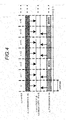
- FIG. 3 is a diagram showing the subframe where UE1 under the control of eNB measures the CQI related to the channel (the channel of the own cell) from eNB to UE1 in the present invention.
- UE1 under the control of eNB is provided with a CQI measurement mode in which the CQI related to the channel (the channel of the own cell) from eNB to UE1 is measured by using the domains of the third and subsequent symbols except for the first two symbols in the subframe shown in FIG. 3 .
- the subframe which is the "MBSFN subframe that RN uses as the backhaul” UE1 under the control of eNB measures the CQI related to the channel (the channel of the own cell) from eNB to UE in the CQI measurement mode described with reference to FIG. 3 .
- UE1 under the control of eNB measures the CQI related to the channel (the channel of the own cell) from eNB to UE in the above-described CQI measurement mode.
- eNB notifies UE1 under its own control of the position of the "MBSFN subframe that RN uses as the backhaul", and in the "MBSFN subframe that RN uses as the backhaul", UE1 under the control of eNB measures the CQI related to the channel (the channel of the own cell) from eNB to UE by using the signals in the domains of the third and subsequent symbols, whereby the CQI when there is no interference from RN can be accurately measured.
- FIG. 6 is a block diagram showing the configuration of the wireless communication terminal 300A according to the present embodiment.
- the wireless communication terminal 300A shown in FIG. 6 is a block diagram showing the configuration of the wireless communication terminal 300A according to the present embodiment.
- a transmission processor 329 includes an antenna 301, a switch (SW) 303, a reception RF section 305, a reception processor 307, a CQI measurement signal extractor 309, a control information acquisition section 317, a CQI measurement controller 319, an RN information acquisition section 311, a signal extraction controller 313, a subframe extractor 315, a symbol extractor 321, a CQI measurement section 323, a CQI memory section 325, a feedback information generator 327, a transmission processor 329, and a transmission RF section 331.
- SW switch
- 303 reception RF section 305
- a reception processor 307 includes an antenna 301, a reception RF section 305, a reception processor 307, a CQI measurement signal extractor 309, a control information acquisition section 317, a CQI measurement controller 319, an RN information acquisition section 311, a signal extraction controller 313, a subframe extractor 315, a symbol extractor 321, a CQI
- the reception RF section 305 On the signals received by the antenna 301, the reception RF section 305 performs filtering processing in order to remove the signals except for the communication bandwidth, performs frequency conversion to the IF frequency bandwidth or to the baseband width, and outputs the resultant signals to the reception processor 307.
- the reception processor 307 performs reception processing on the signals outputted from the reception RF section 305.
- the reception processor 307 separates the data, the reference signal, the control information and the information related to RN that are multiplexed on the received signals, and outputs them.
- the reception processor 307 converts the analog signals to digital signals by an AD converter or the like, and performs demodulation processing, decoding processing and the like.
- the CQI measurement signal extractor 309 extracts the signal used for the CQI measurement in the received signals which signal is separated by the reception processor 307, and outputs it to the subframe extractor 315.
- the signal used for the CQI measurement is, for example, a reference signal when a desired signal component is measured.
- the signal used for the CQI measurement is, for example, a data signal when an interference component is measured.
- the control information acquisition section 317 acquires, of the control information separated by the reception processor 307, the control information for the wireless communication terminal 300A, and outputs the control information related to the CQI measurement for the wireless communication terminal 300A, to the CQI measurement controller 319.
- the CQI measurement controller 319 outputs an instruction to the signal extraction controller 313 so that the CQI measurement method is controlled based on the control information related to the CQI measurement for the wireless communication terminal 300A which information is outputted from the control information acquisition section 317.
- the CQI measurement methods that the CQI measurement controller 319 controls are the CQI measurement method used for the "MBSFN subframe that RN uses as the backhaul" which measurement method has been described with reference to FIGs. 3 and 4 and a normal CQI measurement method.
- the CQI measurement controller 319 determines which of the CQI measurement methods is used based on the control information related to the CQI measurement outputted from the control information acquisition section 317, and provides an instruction as to the result of the determination to the signal extraction controller 313.
- the RN information acquisition section 311 acquires the information related to RN separated by the reception processor 307, and outputs it to the signal extraction controller 313.
- the information related to RN includes the position of the "MBSFN subframe that RN uses as the backhaul".
- the information related to RN is information related to RN connected to eNB.
- the signal extraction controller 313 Based on the instruction from the CQI measurement controller 319, the signal extraction controller 313 outputs an instruction to the subframe extractor 315 and the symbol extractor 321 by using the information related to RN outputted from the RN information acquisition section 311.
- the signal extraction controller 313 instructs the subframe extractor 315 to extract the "MBSFN subframe that RN uses as the backhaul” outputted from the RN information acquisition section, and further, instructs the symbol extractor 321 to extract the domains of the third and subsequent symbols except for the first two symbols in the "MBSFN subframe that RN uses as the backhaul".
- the signal extraction controller 313 instructs the subframe extractor 315 to output all the subframes, and instructs the symbol extractor 321 to extract the domains of all the symbols.
- the subframe extractor 315 extracts the signal used for the CQI measurement extracted by the CQI measurement signal extractor 309, in units of subframes, and outputs it to the symbol extractor 321.
- the subframe extractor 315 may have the function of buffering the signal used for the CQI measurement extracted by the CQI measurement signal extractor 309. Moreover, the subframe extractor 315 may extract the signal in units of subframes from the buffered signal based on the instruction from the signal extraction controller 313 and output it.
- the symbol extractor 321 Based on the instruction from the signal extraction controller 313, the symbol extractor 321 extracts, in the symbol domain, the signal used for the CQI measurement in units of subframes extracted by the subframe extractor 315, and outputs it to the CQI measurement section 323.
- the CQI measurement section 323 performs the measurement of the CQI related to the channel (the channel of the own cell) from eNB to UE by using the signal used for the CQI measurement extracted by the symbol extractor 321, and outputs the measured CQI to the CQI memory section 325.
- a desired signal component is measured
- the CQI measurement section 323 a method is available in which channel estimation is performed by using the reference signal of the received signal and the received power of the desired signal component is measured from the result of the channel estimation.
- an interference component to the CQI measurement section 323, a method is available in which the received power is measured by using the data area and the received power of the desired data is subtracted to thereby measure the receiver power of the interference component. In the latter case, a method is available in which the received power of the desired data is acquired from the received power of the desired signal component described previously.
- the CQI memory section 325 stores the CQI measured by the CQI measurement section therein, and outputs it to the feedback information generator 327.
- the feedback information generator 327 generates information to be fed back to the base station 100 by using the CQI stored in the CQI memory section 325, and outputs it to the transmission processor 329.
- the transmission processor 329 performs transmission processing on the feedback information generated by the feedback information generator 327 so that it can be fed back to the base station 100, and outputs the information to the transmission RF section 331.
- Examples of the transmission processing include multiplexing of signals such as transmission data and feedback information, coding processing and modulation processing.
- the transmission RF section 331 performs frequency conversion to the RF frequency, power amplification and transmission filtering processing on the transmission signal having undergone the transmission processing by the transmission processor, and outputs the signal to the antenna 301.
- FIG. 7 is a block diagram showing the configuration of the base station 100 according to the present embodiment.
- the base station 100 shown in FIG. 7 includes a CQI measurement method instruction section 113, a control information generator 111, a signal multiplexer 109, a transmission processor 107, a transmission RF section 105, a reception RF section 123, a reception processor 121, a CQI information extractor 119, a CQI memory section 117, and a scheduler 115.
- inputted to the signal multiplexer 109 are the reference signal, transmission data and RN information.
- the reference signal is constituted by a known signal between transmission and reception, and is inputted to the signal multiplexer 109.
- the reference signal is used, for example, for the estimation of the channel for demodulation on the receiving side and the CQI measurement.
- the transmission data is transmission data to the wireless communication terminals 300A and 300B, and is inputted to the signal multiplexer 109.
- the RN information is information related to the relay node (RN) connected to the base station 100, and is inputted to the signal multiplexer 109.
- the CQI measurement method instruction section 113 outputs, to the control information generator 111, an instruction to control the CQI measurement used in the wireless communication terminal 300A.
- the CQI measurement method instruction section 113 may be provided in the wireless communication terminal 300A.
- the wireless communication terminal 300A may determine whether the subframe is the "MBSFN subframe that RN uses as the backhaul" or not and control the CQI measurement method.
- the wireless communication terminal 300A always performs both the CQI measurement in the "MBSFN subframe that RN uses as the backhaul" and the CQI measurement in the normal subframe and reports the result, the CQI measurement method instruction section 113 is unnecessary.
- the control information generator 111 generates control information related to the wireless communication terminal 300A including the instruction to control the CQI measurement outputted from the CQI measurement method instruction section 113, and outputs it to the signal multiplexer 109.
- the signal multiplexer 109 multiplexes the inputted reference signal, transmission data to the wireless communication terminals, RN information and control information, and outputs the result to the transmission processor 107. Based on the scheduling information outputted from the scheduler 115 described later, the signal multiplexer 109 allocates the transmission data to the wireless communication terminals 300A and 300B, performs user multiplexing, and performs multiplexing with other signals.
- the transmission processor 107 performs transmission processing on the signal multiplexed by the signal multiplexer 109, and outputs the signal to the transmission RF section 105. Examples of the transmission processing include coding processing and modulation processing.
- the transmission RF section 105 performs frequency conversion to the RF frequency, power amplification and transmission filtering processing on the transmission signal having undergone the transmission processing by the transmission processor 107, and outputs the signal to an antenna 101.
- the reception RF section 123 On the signals received by the antenna, the reception RF section 123 performs filtering processing in order to remove the signals except for the communication bandwidth, performs frequency conversion to the IF frequency bandwidth or to the baseband width, and outputs the resultant signal to the reception processor 121.
- the reception processor 121 performs reception processing on the signals outputted from the reception RF section 123, and separates the reception data, the control information and the like. Specifically, the reception processor 121 converts the analog signals to digital signals by an AD converter or the like, and performs demodulation processing, decoding processing and the like.
- the CQI information extractor 119 extracts CQI information from the control information separated by the reception processor 121, and outputs it to the CQI memory section 117.
- the CQI memory section 117 stores the CQI information extracted by the CQI information extractor 119, and outputs it to the scheduler 115.
- the scheduler 115 performs scheduling by using the CQI information stored in the CQI memory section 117, and outputs scheduling information to the signal multiplexer 109. In the scheduling, the scheduler 115 determines the transmission subframe and the transmission frequency (resource block) by using the CQI information
- FIG. 8 is a diagram showing the processing flow of the CQI measurement at the wireless communication terminal 300A.
- the antenna 301 receives a signal from eNB, and the reception RF section 305 and the reception processor 307 perform reception processing.
- the CQI measurement signal extractor 309 extracts the signal used for the CQI measurement from the signal having undergone the reception processing at step (ST001).
- control information acquisition section 317 acquires the control information for the UE1 under the control of eNB, from the signal having undergone the reception processing at step (ST001).
- the RN information acquisition section 311 acquires the information related to RN, from the signal having undergone the reception processing at step (ST001).
- the CQI measurement controller 319 selects in which of the CQI measurement mode for the "MBSFN subframe that RN uses as the backhaul" and the normal CQI measurement mode the CQI is measured, from the control information acquired at step (ST003).
- the signal extraction controller 313 indicates, to the subframe extractor 315 and the symbol extractor 321, the subframe which is the "MBSFN subframe that RN uses as the backhaul" from the information related to RN acquired at step (ST004).
- the subframe extractor 315 extracts the subframe which is the "MBSFN subframe that RN uses as the backhaul" from the signal used for the CQI measurement extracted at step (ST002) in the subframe which is the "MBSFN subframe that RN uses as the backhaul” indicated by the signal extraction controller 313 at step (ST006-1).
- the symbol extractor 321 extracts the signals of the domains except for the first two symbols, from the signal of the subframe extracted at step (ST007-1) in the subframe which is the "MBSFN subframe that RN uses as the backhaul" notified by the signal extraction controller 313 at step (ST006-1).
- the signal extraction controller 313 instructs the subframe extractor 315 and the symbol extractor 321 to perform signal extraction in all the subframes.
- the subframe extractor 315 extracts all the subframes of the signal used for the CQI measurement extracted at step (ST002) as instructed by the signal extraction controller 313 at step (ST006-2).
- the symbol extractor 321 extracts the signals of all the symbol domains in the signals of all the subframes extracted at step (ST007-2) as instructed by the signal extraction controller 313 at step (ST006-2).
- the CQI measurement section 323 performs the CQI measurement by using the signals extracted at step (ST008-1) or (ST008-2).
- the CQI memory section stores the CQI measured at (ST009).
- the feedback information generator 327 generates the feedback information from the CQI stored at step (ST010).
- the transmission processor 329 and the transmission RF section 331 perform the transmission processing on the feedback information generated at step (ST011), and transmits the result to eNB.
- UE1 under the control of eNB measures the CQI by using the domains of the third and subsequent symbols except for the first two symbols in the subframe which is the "MBSFN subframe that RN uses as the backhaul"
- the present invention is not limited to this subframe.
- UE1 under the control of eNB may measure the CQI related to the channel (the channel of the own cell) from eNB to UE1 by using the domains of the third and subsequent symbols except for the first two symbols.
- the overhead of signaling can be reduced since it is unnecessary for eNB to notify the information related to the MBSFN subframe used as the backhaul of the neighbor RN, and the like.
- the transmission power of the reference signal may be increased.
- the CQI measurement mode of UE1 under the control of eNB in the present embodiment since the first two symbols cannot be used for the CQI measurement, by increasing the power accordingly, the CQI measurement accuracy can be maintained.
- eNB notifies UE1 under the control of eNB how much the transmission power has been increased.
- the reference signal may be inserted in part of the data domains of the third and subsequent symbols. Since the first two symbols cannot be used for the CQI measurement, by inserting the reference signal corresponding thereto, the CQI measurement accuracy can be maintained. In this case, eNB notifies UE1 under the control of eNB that the reference signal has been inserted for the CQI measurement.
- UE1 under the control of eNB may measure the CQI in the above-described CQI measurement mode in the "MBSFN subframe that RN uses as the backhaul" which is prior to the fourth subframe and is the closest.
- FIG. 5 is a diagram showing another example of the downlink channel in the present embodiment in the case of the periodic CQI.
- UE1 under the control of eNB may measure the CQI related to the channel (the channel of the own cell) from eNB to UE1 in the above-described CQI measurement mode of the present embodiment and notify eNB of it on the uplink channel of the subframe [n+8].
- UE1 under the control of eNB may measure the CQI related to the channel (the channel of the own cell) from eNB to UE1 in the CQI measurement mode of the present embodiment. For example, explaining this similarly by using FIG. 5 is as follows:
- UE1 under the control of eNB knows the position of the subframe which is the "MBSFN subframe used as the backhaul of RN". Therefore, for example, in the subframe [n+2] shown in FIG. 5 , when UE1 under the control of eNB is instructed to measure the CQI related to the channel (the channel of the own cell) from eNB to UE1, UE1 under the control of eNB may measure the CQI related to the channel (the channel of the own cell) from eNB to UE1 in the CQI measurement mode of the present embodiment.
- eNB may instructs UE1 under the control of eNB in the PDCCH to perform measurement in the CQI measurement mode for the "MBSFN subframe that RN uses as the backhaul". Specifically, in the format 0 of the PDCCH, a CQI request for the "MBSFN subframe used as the backhaul of RN" is added.
- UE1 under the control of eNB can measure the CQI related to the channel (the channel of the own cell) from eNB to UE1 in the CQI measurement mode of the present embodiment.
- UE1 under the control of eNB may measure, a plurality of number of times, the CQI related to the channel (the channel of the own cell) from eNB to UE1 measured in the "MBSFN subframe that RN uses as the backhaul" and average it.
- the range where the signal component is measured is performed is limited to the "MBSFN subframe that RN uses as the backhaul”
- the range where the interference component is measured is performed is limited to the "MBSFN subframe that RN uses as the backhaul”.
- the present invention may be applied to a case where in a plurality of eNBs, there is a subframe where no signal is transmitted from one eNB.
- the channel quality of the own cell is described as the channel quality of the own cell in the present embodiment, the present invention is not limited thereto.
- the channel quality of the own cell measured when handover is performed may be used.
- a first modification of the present embodiment will be described. While a case where the number of RNs connected to eNB is one is described as an example in the above-described embodiment, in the first modification of the present embodiment, a case where a plurality of RNs are connected to one eNB will be described.
- the amount of interference differs among the subframes. That is, when the position of UE under the control of eNB is close to RN, the interference received from the RN is strong, and when it is far from RN, the interference received from the RN is weak. Consequently, it is preferable for UE under the control of eNB to have signals transmitted from a subframe where the interference is weaker.
- FIG. 9 is a diagram showing a wireless communication system that relays radio signals by using the relay technology in the first modification of the present embodiment.
- eNB represents a base station 400
- RN1 represents a relay node 500A
- RN2 represents a relay node 500B
- UE1 represents a wireless communication terminal 600.
- the wireless communication terminal 600 (UE1) is a wireless communication terminal connected to the base station 400, in other words, a wireless communication terminal under the control of the base station 400.
- the positional relationship among the wireless communication terminal 600, the relay node 500A (RN1) and the relay node 500B (RN2) is such that the relay node 500B (RN2) is in a position closer to the wireless communication terminal 600 (UE1) than the relay node 500A (RN1).
- the relay method is such that the backhaul channel and the access channel are accommodated in the same frequency bandwidth and the backhaul channel and the access channel of RN are allocated while being divided by the time domain (in units of subframes).
- the base station 400 will be referred to as eNB; the relay node 500A, as RN1; the relay node 500B, as RN2; and the wireless communication terminal 600 under the control of the base station 400, as UE1.
- the relay node 500A (RN1) and the relay node 500B (RN2) have an individual cell ID studied in LTE-A. Therefore, the relay node 500 (RN1) and the relay node 500B adjacent to the wireless communication terminal 600 can be regarded as neighbor cells when viewed from the wireless communication terminal 600.
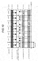
- FIG. 10 is a diagram showing the subframes on the downlink channel in the first modification.
- the positions of the "MBSFN subframes that RN uses as the backhaul" are the subframes [n+2] and [n+6].
- the position of the "MBSFN subframe that RN uses as the backhaul” is the subframe [n+4].
- UE1 receives interferences from both RN1 and RN2 as shown by the arrows (broken lines).
- the amounts of interferences from the two RN1 and RN2 are different. That is, since RN1 is situated farther from UE1 than RN2, the amount of interference that UE1 receives from RN1 is weaker than the amount of interference that UE1 receives from RN2.
- the amount of interference that UE1 receives from RN is weaker in the subframe [n+4] where UE1 receives an interference from RN1 than in the subframes [n+2, n+6] where UE1 receives an interference from RN2.
- UE1 under the control of eNB is notified of the positions of the MBSFN subframes used as the backhaul at all the RNs under the control of eNB, and UE1 under the control of eNB detects a subframe where the interference is small and feeds back the position of the subframe to eNB together with the CQI related to the channel (the channel of the own cell) from eNB to UE1.
- a concrete method of the first modification considering the amounts of interferences from RNs that UE receives will be described.
- eNB notifies UE1 under its own control of the position of the "MBSFN subframe that RN uses as the backhaul" at all the RNs connected to eNB.
- the notification method includes a method in which notification is provided by using system information (system information block), control information of a higher-level layer or the like.
- UE1 under the control of eNB measures the CQI related to the channel (the channel of the own cell) from eNB to UE1 in the CQI measurement mode described with reference to FIG. 3 in the subframe notified by eNB. Then, UE1 detects a subframe where the CQI is high from among the notified subframes, and feeds back the CQI and the position of the subframe to eNB. For example, explaining the environment assumed in FIGs.
- UE1 measures the CQI for the "MBSFN subframe that RN uses as the backhaul" in the subframes [n+2, n+4, n+6], detects the subframe [n+4] where the amount of interference is small from thereamong, and feeds back the CQI in the subframe [n+4] and the subframe number.
- eNB notifies UE1 under the control of eNB of the position of the "MBSFN subframe that RN uses as the backhaul" at all the RNs under the control of eNB, and UE1 under the control of eNB detects a subframe where the interference is small and feeds back the position of the subframe to eNB together with the CQI related to the channel (the channel of the own cell) from eNB to UE1. Consequently, in the first modification of the present embodiment, at UE1 under the control of eNB, the CQI related to the channel (the channel of the own cell) from eNB to UE1 can be measured in the subframe where the interference from RN is smaller.
- FIG. 11 is a block diagram showing the configuration of the wireless communication terminal 600 in the first modification.
- the wireless communication terminal 600 shown in FIG. 11 is different from the wireless communication terminal 300A shown in FIG. 6 in that a high quality subframe detector 601 and a feedback information generator 603 are provided. Except for this, the configuration is similar to that of the embodiment, and in FIG. 11 , elements in common with FIG. 6 are denoted by the same reference numerals. Moreover, descriptions of the common elements are omitted.
- the high quality subframe detector 601 detects the CQI of the highest quality from among the CQIs stored in the CQI memory section 325. Then, the high quality subframe detector 601 measures the CQI for the "MBSFN subframe that RN uses as the backhaul" by using the information on the position of the "MBSFN subframe that RN uses as the backhaul" acquired by the RN information acquisition section 311, detects the position of the subframe where the CQI is of high quality, and outputs the detection result (the subframe number and the CQI related to the channel [the channel of the own cell] from eNB to UE1 in the subframe) to the feedback information generator 603.
- the feedback information generator 603 generates feedback information from the subframe information (subframe number) detected by the high quality subframe detector 601 and the CQI related to the channel (the channel of the own cell) from eNB to UE1 in the subframe stored in the CQI memory section 325, and outputs it to the transmission processor 329.
- FIG. 12 is a block diagram showing the configuration of the base station 400 in the first modification.
- the base station 400 shown in FIG. 12 is different from the base station 100 shown in FIG. 7 in that a CQI/subframe memory section 401 is provided instead of the CQI memory section 117. Except for this, the configuration is similar to that of the embodiment, and in FIG. 12 , elements in common with FIG. 7 are denoted by the same reference numerals. Moreover, descriptions of the common elements are omitted.
- the CQI/subframe memory section 401 stores the subframe information fed back from UE1 and the CQI related to the channel (the channel of the own cell) from eNB to UE1 in the subframe which information and CQI are extracted by the CQI information extractor 119, and outputs them to the scheduler 115.
- FIG. 13 is a diagram showing the processing flow of the CQI measurement at the wireless communication terminal 600 in the first modification.
- the processing flow of the CQI measurement at the wireless communication terminal 600 shown in FIG. 13 is different from the processing flow of the CQI measurement at the wireless communication terminal 300A shown in FIG. 8 in that the processing of step (ST013) is newly added between step (ST010) and step (ST011). Except for this, the processing flow is similar to that of the embodiment, and in FIG. 13 , steps in common with FIG. 8 are denoted by the same reference numerals. Moreover, descriptions of the common steps are omitted.
- the high quality subframe detector 601 detects the subframe where the quality is high in the CQI stored at step (ST010). Then, at (ST011), the feedback information generator 603 generates feedback information from the CQI stored at step (ST010) and the subframe information detected at (ST013).
- eNB notifies UE1 under its own control of the position of the "MBSFN subframe that RN uses as the backhaul" at all the connected RNs
- the present invention is not limited thereto.
- eNB notifies UE1 under the control of eNB of the number of each RN and the position of the MBSFN subframe used as the backhaul by each RN which position is associated with the number of the RN. Then, the UE1 detects the subframe where the CQI is the highest, and detects by which RN the subframe is used as the MBSFN subframe used as the backhaul, thereby feeding back the position of the subframe or the RN number and the measured CQI to eNB.
- the accuracy of measurement of the CQI can be improved.
- eNB notifies UE1 of the position of the "MBSFN subframe that RN uses as the backhaul", and UE1 switches the CQI measurement mode based on the notified information.
- UE1 itself determines whether the subframe is the "MBSFN subframe that RN uses as the backhaul" or not.
- FIG. 14 is a diagram showing a wireless communication system that relays radio signals by using the relay technology in the second modification.
- eNB represents a base station 700
- RN represents a relay node 800
- UE1 represents a wireless communication terminal 900A
- UE2 represents a wireless communication terminal 900B.
- the wireless communication terminal 900A (UE1) is a wireless communication terminal connected to the base station 700
- the wireless communication terminal 900B (UE2) is a wireless communication terminal connected to the relay node 800 (RN).
- the wireless communication terminal 900A (UE1) is the wireless communication terminal (UE1) under the control of the base station 700.
- the base station 700 will be referred to as eNB; the relay node 800, as RN; and the wireless communication terminal 900A (UE1), as UE1.
- RN receives signals from eNB on the backhaul channel (the arrow E in the figure), and transmits the signals to UE2 on the access channel of RN (the arrow F in the figure).
- the relay method is such that the backhaul channel and the access channel are accommodated in the same frequency bandwidth and the backhaul channel and the access channel of RN are allocated while being divided by the time domain (in units of subframes).
- the relay node 800 (RN) has an individual cell ID studied in LTE-A. Therefore, the relay node 800 (RN) adjacent to the wireless communication terminal 900A (UE1) can be regarded as a neighbor cell when viewed from the wireless communication terminal 900A.
- FIG. 15 shows an example of symbols of a subframe on the downlink channel in the second modification.
- FIG. 16 shows another example of symbols of a subframe on the downlink channel in the second modification.
- signals are transmitted from RN at all the symbols. For this reason, whichever symbol of this subframe is used to measure the CQI related to the channel (the channel of the own cell) from eNB to UE1, the CQIs show close values. That is, the CQI related to the channel (the channel of the own cell) from eNB to UE1 measured by using the domains of all the symbols and the CQI related to the channel (the channel of the own cell) from eNB to UE1 measured by using the third and subsequent symbols are close values.
- the amount of interference that UE1 receives from RN is different between when the CQI related to the channel (the channel of the own cell) from eNB to UE1 is measured with the first two symbols being included and when the CQI of eNB is measured by using the third and subsequent symbols. That is, the CQI related to the channel (the channel of the own cell) from eNB to UE1 measured by using the third and subsequent symbols in the subframe shown in FIG.
- the 16 assumes a value showing higher channel quality than the CQI related to the channel (the channel of the own cell) from eNB to UE1 measured by using the first two symbols and the third and subsequent symbols in the subframe shown in FIG. 16 . That is, between the CQI related to the channel (the channel of the own cell) from eNB to UE1 measured by using the domains of all the symbols and the CQI related to the channel (the channel of the own cell) from eNB to UE1 measured by using the third and subsequent symbols, the latter assumes a value showing higher channel quality.
- UE1 itself can determine whether the subframe is the normal subframe or the "MBSFN subframe that RN uses as the backhaul".
- UE1 itself can similarly determine whether the subframe is the normal subframe or the "MBSFN subframe that RN uses as the backhaul".
- UE1 compares the CQI related to the channel (the channel of the own cell) from eNB to UE1 measured by using the first two symbols and the CQI related to the channel (the channel of the own cell) from eNB to UE1 measured by using the third and subsequent symbols to determine whether the subframe of RN is the normal subframe or the "MBSFN subframe that RN uses as the backhaul", and UE1 performs the measurement of the CQI of eNB suitable for each and feeds back the result to eNB.
- UE1 measures the CQI related to the channel (the channel of the own cell) from eNB to UE1 by using all the symbol domains, and then, measures the CQI related to the channel (the channel of the own cell) from eNB to UE1 by using the domains of the third and subsequent symbols.
- CQI_all the CQI related to the channel (the channel of the own cell) from eNB to UE1 measured by using all the symbol domains
- CQI_part the CQI related to the channel (the channel of the own cell) from eNB to UE1 measured by using the domains of the third and subsequent symbols
- the underscore “_” subsequent to “CQI” represents that the letters or the word (e.g. all and part) subsequent to the underscore _ is subscripts of the "CQI" immediately preceding the underscore _.
- UE1 compares CQI_all and CQI_part to determine whether the subframe of RN is the normal subframe or the "MBSFN subframe that RN uses as the backhaul". For example, UE1 can determine whether the subframe of RN is the normal subframe or the subframe of RN is the "MBSFN subframe that RN uses as the backhaul” by presetting a threshold value Th for the absolute value of the difference between CQI_all and CQI_part (hereinafter, referred to as CQI difference) and comparing the CQI difference with the threshold value Th.
- CQI difference the absolute value of the difference between CQI_all and CQI_part
- UE1 determines that there is no difference between CQI_all and CQI_part, and determines that the subframe of RN is the normal subframe.
- the CQI difference is equal to or more than the threshold value Th, UE1 determines that there is a difference between CQI_all and CQI_part, and UE1 determines that the subframe of RN is the "MBSFN subframe that RN uses as the backhaul".
- the determination condition expressed by the above-described CQI difference and the threshold value Th is expressed by the following expression (1) and expression (2) by using CQI_all and CQI_part: [Expression 1]
- UE1 determines that the subframe of RN is the normal subframe.
- CQI_all, CQI_part and the threshold value Th satisfy the expression (2), UE1 determines that the subframe of RN is the "MBSFN subframe that RN uses as the backhaul".
- UE1 selects the CQI measurement method, for example, as follows:
- UE1 determines that the subframe of RN is the normal subframe, since the quality is the same among the symbols in the subframe, the accuracy of the CQI measurement can be improved by performing averaging by using a multitude of symbols. Therefore, UE1 selects the CQI measurement method using all the domains of the subframe, and measures the CQI related to the channel (the channel of the own cell) from eNB to UE1.
- UE1 determines that the subframe of RN is the "MBSFN subframe that RN uses as the backhaul", as in the first modification, UE1 selects the CQI measurement mode using the domains of the third and subsequent symbols except for the first two symbols, and measures the CQI related to the channel (the channel of the own cell) from eNB to UE1.
- UE1 feeds back in which mode the measurement was performed, to eNB as feedback information together with the measured CQI.
- CQI measurement is performed, as the CQI measurement using the first two symbols, by using the reference signal inserted in the symbol #0 and, as the CQI measurement using the third and subsequent symbols, by using the reference signal inserted in the symbol #7.
- CQI_sym0 and CQI_sym7 are each shown.
- CQI_sym difference a threshold value for the absolute value of the difference between CQI_sym0 and CQI_sym7 (hereinafter, referred to as CQI_sym difference) and by comparing CQI_sym difference with the threshold value Th_sym, UE1 can determine whether the subframe of RN is the normal subframe or the "MBSFN subframe that RN uses as the backhaul.
- UE1 determines that the quality is the same among the symbols in the subframe, and UE1 determines that the subframe of RN is the normal subframe.
- UE1 determines that there is a quality difference between the first two symbols and the third and subsequent symbols since there is a difference between CQI_sym0 and CQI_sym7, and UE1 determines that the subframe of RN is the "MBSFN subframe that RN uses as the backhaul".
- the determination condition expressed by the above-described CQI_sym difference and the threshold value Th_sym is expressed by the following expression (3) and expression (4) by using CQI_sym0, CQI_sym7 and Th_sym: [Expression 3]
- Expression 4
- UE1 determines that the subframe of RN is the normal subframe.
- CQI_sym0, CQI_sym7 and Th_sym satisfy the expression (3)
- UE1 determines that the subframe of RN is the "MBSFN subframe that RN uses as the backhaul”.
- the CQI measurement method is selected.
- the subframe of RN is the normal subframe, since the quality is the same among the symbols in the subframe, the accuracy of the CQI measurement can be improved by performing averaging by using a multitude of symbols, and for this reason, UE1 selects the CQI measurement method using all the domains of the subframe, and measures the CQI related to the channel (the channel of the own cell) from eNB to UE1.
- UE1 selects the CQI measurement mode using the domains of the third and subsequent symbols except for the first two symbols, and measures the CQI related to the channel (the channel of the own cell) from eNB to UE1. UE1 feeds back in which mode the measurement was performed, to eNB as feedback information together with the measured CQI.
- UE1 compares the CQI related to the channel (the channel of the own cell) from eNB to UE1 measured by using the first two symbols and the CQI related to the channel (the channel of the own cell) from eNB to UE1 measured by using the third and subsequent symbols. Then, based on the result of the comparison, UE1 determines whether the subframe of RN is the normal subframe or the "MBSFN subframe that RN uses as the backhaul". Further, based on the result of the determination, UE1 performs the measurement of the CQI of eNB suitable for each, and feeds back in which mode the measurement was performed, to eNB as feedback information together with the measured CQI.
- the CQI related to the channel (the channel of the own cell) from eNB to UE1 when there is no interference from RN can be accurately measured.
- FIG. 17 is a block diagram showing the configuration of the wireless communication terminal 900 in the second modification.
- the wireless communication terminal 900 shown in FIG. 17 includes the antenna 301, the switch (SW) 303, the reception RF section 305, the reception processor 307, the CQI measurement signal extractor 309, a symbol extractor 901, a CQI measurement section 903A, a CQI measurement section 903B, a subframe determiner 905, a CQI memory section 907, a feedback information generator 909, the transmission processor 329, and the transmission RF section 331.
- the wireless communication terminal 900 shown in FIG. 17 is different from the wireless communication terminal 300A shown in FIG. 6 in the symbol extractor 901, the CQI measurement section 903A, the CQI measurement section 903B, the subframe determiner 905, the CQI memory section 907 and the feedback information generator 909. Except for these, the configuration is similar to that of the embodiment, and in FIG. 17 , elements in common with FIG. 6 are denoted by the same reference numerals. Moreover, descriptions of the common elements are omitted.
- the symbol extractor 901 extracts the signals of the domains of the third and subsequent symbols except for the first two symbols, from the signals used for the CQI measurement which signals are extracted from the CQI measurement signal extractor 309, and outputs them to the CQI measurement section 903A.
- the CQI measurement section 903A inputs the signals used for the CQI measurement of the domains of the third and subsequent symbols which signals are extracted by the symbol extractor 901, measures the CQI when the subframe is the "MBSFN subframe that RN uses as the backhaul" as in the embodiment, and outputs the measured CQI to the subframe determiner 905.
- the CQI measurement section 903B inputs the signals used for the CQI measurement, performs the CQI measurement by using all the symbols, and outputs the measured CQI to the subframe determiner 905.
- the subframe determiner 905 compares the CQIs measured by the CQI measurement section 903A and the CQI measurement section 903B, and determines whether the subframe of RN is the normal subframe or the "MBSFN subframe that RN uses as the backhaul". Then, the subframe determiner 905 outputs the CQI to the CQI memory section 907 together with the result of the determination.
- the CQI measurement result from the CQI measurement section 903B is outputted to the CQI memory section 907.
- the subframe determiner 905 determines that the subframe of RN is the "MBSFN subframe that RN uses as the backhaul"
- the CQI measurement result from the CQI measurement section 903A is outputted to the CQI memory section 907.
- the CQI memory section 907 stores the value of the CQI inputted from the subframe determiner 905 and the result of the determination of the subframe of RN, and outputs them to the feedback information generator 909.
- the feedback information generator 909 generates the feedback information to be fed back to the base station 700, by using the CQI and the result of the determination of the subframe of RN stored in the CQI memory section 907, and outputs it to the transmission processor 329.
- FIG. 18 is a block diagram showing the configuration of the base station 700 in the second modification.
- the base station 700 shown in FIG. 18 is different from the base station 100 shown in FIG. 7 in that instead of the CQI information extractor 119 and the CQI memory section 117, a CQI information/determination result extractor 701 and a CQI/determination result memory section 703 are present and that the RN information and the CQI measurement method instruction section 113 are absent. Except for these, the configuration is similar to that of the embodiment, and in FIG. 18 , elements in common with FIG. 7 are denoted by the same reference numerals. Moreover, descriptions of the common elements are omitted.
- the CQI information/determination result extractor 701 extracts the subframe information fed back from the wireless communication terminal 900 and the CQI in the subframe, from the control information separated by the reception processor 121, and outputs them to the CQI/determination result memory section 703.
- the CQI/determination result memory section 703 stores the subframe information fed back from the wireless communication terminal 900 and the CQI in the subframe, and outputs them to the scheduler 115.
- FIG. 19 is a diagram showing the processing flow of the CQI measurement of the wireless communication terminal 900 in the second modification.
- the antenna 301 receives the signal from eNB, and the reception RF section 305 and the reception processor 307 perform reception processing.
- the CQI measurement signal extractor 309 extracts the signal used for the CQI measurement from the signal having undergone the reception processing at step (ST101).
- the symbol extractor 901 extracts the symbols of the domains except for the first two symbols in the signal used for the CQI measurement extracted at step (ST102).
- the CQI measurement section 903A performs the CQI measurement by using the signal extracted at step (ST103).
- the result of the CQI measurement by the CQI measurement section 903A will be referred to as CQI1.
- the CQI measurement section 903B performs the CQI measurement by using the signals of all the symbol domains at the signal used for the CQI measurement extracted at step (ST102).
- the result of the CQI measurement by the CQI measurement section 903B will be referred to as CQ12.
- the subframe determiner 905 compares CQI1 and CQI2 which are the measurement results of the CQIs measured at step (ST104-1) and step (ST104-2), and determines whether the subframe of RN is the normal subframe or the "MBSFN subframe that RN uses as the backhaul".
- Examples of the determination method include a method in which the determination is performed by using the expression (1) and the expression (2) and a method in which the determination is performed by using the expression (3) and the expression (4).
- the CQI memory section 907 stores the result of the determination and CQI1.
- the CQI memory section 907 stores the result of the determination and CQI2.
- the feedback information generator 909 generates feedback information from the result of the subframe determination and the value of the CQI stored at step (ST106-1) or step (ST106-2).
- the transmission processor 329 and the transmission RF section 331 performs transmission processing on the feedback information generated at step (ST107), and transmits the result to eNB.
- UE1 compares the CQI of eNB measured by using the first two symbols and the CQI of eNB measured by using the third and subsequent symbols and determines whether the subframe of RN is the normal subframe or the "MBSFN subframe that RN uses as the backhaul", and UE1 performs the measurement of the CQI of eNB suitable for each and feeds back the result to eNB.
- the CQI when there is no interference from RN can be accurately measured.
- the overhead of signaling on the downlink channel can be reduced.
- the antenna port refers to a logical antenna including one or more than one physical antenna. That is, the antenna port does not always refer to one physical antenna but sometimes refers to an array antenna or the like including a plurality of antennas. For example, in LTE, how many physical antennas an antenna port includes is not defined, and reference signals of different base stations are defined as minimum units that can be transmitted. Moreover, the antenna port is sometimes defined as a minimum unit that is multiplied by the weighting of a precoding vector.
- the functional blocks used for the description of the embodiment are typically implemented as an LSI which is an integrated circuit. These may be individually formed as one chip or may be formed as one chip so as to include some or all. While an LSI is cited in this description, it is sometimes called an IC, a system LSI, a super LSI or an ultra LSI according to the difference in integration degree.
- the method of circuit integration is not limited to an LSI; the functional blocks may be implemented as a dedicated circuit or a general purpose processor.
- a programmable FPGA Field Programmable Gate Array
- a reconfigurable processor where the connection and setting of the circuit cells in the LSI are reconfigurable may be used.
Landscapes
- Engineering & Computer Science (AREA)
- Signal Processing (AREA)
- Computer Networks & Wireless Communication (AREA)
- Quality & Reliability (AREA)
- Mobile Radio Communication Systems (AREA)
Priority Applications (1)
| Application Number | Priority Date | Filing Date | Title |
|---|---|---|---|
| PL10774746T PL2432291T3 (pl) | 2009-05-15 | 2010-05-14 | Terminal łączności bezprzewodowej i sposób prowadzenia łączności |
Applications Claiming Priority (2)
| Application Number | Priority Date | Filing Date | Title |
|---|---|---|---|
| JP2009119104 | 2009-05-15 | ||
| PCT/JP2010/003289 WO2010131487A1 (ja) | 2009-05-15 | 2010-05-14 | 無線通信端末及び通信方法 |
Publications (3)
| Publication Number | Publication Date |
|---|---|
| EP2432291A1 EP2432291A1 (en) | 2012-03-21 |
| EP2432291A4 EP2432291A4 (en) | 2017-03-29 |
| EP2432291B1 true EP2432291B1 (en) | 2018-07-18 |
Family
ID=43084870
Family Applications (1)
| Application Number | Title | Priority Date | Filing Date |
|---|---|---|---|
| EP10774746.1A Active EP2432291B1 (en) | 2009-05-15 | 2010-05-14 | Wireless communication terminal and communication method |
Country Status (15)
| Country | Link |
|---|---|
| US (8) | US9392480B2 (pl) |
| EP (1) | EP2432291B1 (pl) |
| JP (2) | JP5674205B2 (pl) |
| KR (1) | KR101654396B1 (pl) |
| CN (2) | CN102428737B (pl) |
| AU (1) | AU2010248656B2 (pl) |
| BR (1) | BRPI1012199B1 (pl) |
| DK (1) | DK2432291T3 (pl) |
| ES (1) | ES2690659T3 (pl) |
| HU (1) | HUE040028T2 (pl) |
| PL (1) | PL2432291T3 (pl) |
| PT (1) | PT2432291T (pl) |
| RU (1) | RU2532271C2 (pl) |
| SG (1) | SG175416A1 (pl) |
| WO (1) | WO2010131487A1 (pl) |
Families Citing this family (11)
| Publication number | Priority date | Publication date | Assignee | Title |
|---|---|---|---|---|
| KR101688250B1 (ko) * | 2009-06-10 | 2016-12-20 | 선 페이턴트 트러스트 | 단말 장치, 기지국 장치, 통신 방법, 및 집적 회로 |
| US9438366B2 (en) * | 2010-02-19 | 2016-09-06 | Qualcomm Incorporated | System access for heterogeneous networks |
| EP2624487B1 (en) | 2010-09-30 | 2018-12-05 | LG Electronics Inc. | Method for computing a channel quality indicator by a user equipment in a wireless communication system and corresponding user equipment |
| US20150072719A1 (en) * | 2011-12-13 | 2015-03-12 | Kyocera Corporation | Mobile terminal, wireless communication system and wireless communication method |
| KR102000093B1 (ko) * | 2012-01-27 | 2019-07-15 | 삼성전자주식회사 | 무선 통신 시스템에서 데이터를 송수신하는 방법 및 장치 |
| JP2016508341A (ja) * | 2013-01-15 | 2016-03-17 | 富士通株式会社 | 基地局間機能のネゴシエーション方法、装置及びシステム |
| US9590878B2 (en) * | 2013-01-16 | 2017-03-07 | Qualcomm Incorporated | Channel state information and adaptive modulation and coding design for long-term evolution machine type communications |
| KR102228883B1 (ko) * | 2013-11-29 | 2021-03-17 | 삼성전자주식회사 | 백홀을 통하여 기지국들 간 정보를 공유하는 멀티 셀 시스템에서 셀 간 간섭을 제거하는 장치 및 방법 |
| CN107852271B (zh) * | 2015-05-15 | 2021-04-20 | 瑞典爱立信有限公司 | 用于跨多个子帧接收或传送下行链路传送的方法和装置 |
| EP4044461A3 (en) * | 2017-05-31 | 2022-11-02 | Fraunhofer-Gesellschaft zur Förderung der angewandten Forschung e.V. | Apparatus, measurement system for testing an apparatus and methods for operating the same |
| WO2023117157A1 (en) | 2021-12-20 | 2023-06-29 | Telefonaktiebolaget Lm Ericsson (Publ) | Method and apparatus for verifying a channel quality indicator measurement |
Family Cites Families (15)
| Publication number | Priority date | Publication date | Assignee | Title |
|---|---|---|---|---|
| EP1481482B1 (en) * | 2002-02-28 | 2012-05-23 | TELEFONAKTIEBOLAGET LM ERICSSON (publ) | Signal receiver devices and methods |
| KR100837351B1 (ko) | 2002-04-06 | 2008-06-12 | 엘지전자 주식회사 | 이동통신 시스템의 무선링크 파라미터 갱신 방법 |
| US7209712B2 (en) | 2002-09-23 | 2007-04-24 | Qualcomm, Incorporated | Mean square estimation of channel quality measure |
| US9184898B2 (en) * | 2005-08-01 | 2015-11-10 | Google Technology Holdings LLC | Channel quality indicator for time, frequency and spatial channel in terrestrial radio access network |
| JP4952135B2 (ja) * | 2006-08-17 | 2012-06-13 | 富士通株式会社 | 無線端末、中継局、無線基地局及び通信方法 |
| MX2009004605A (es) * | 2006-11-01 | 2009-05-15 | Qualcomm Inc | Multiplexacion de control y datos con diversos desplazamientos de energia en un sistema sc-fdma. |
| CN101222728B (zh) * | 2007-01-09 | 2010-08-25 | 华为技术有限公司 | 在ofdma系统中使用时频资源的方法及系统 |
| KR100987266B1 (ko) * | 2007-02-14 | 2010-10-12 | 삼성전자주식회사 | 단일 반송파 주파수 분할 다중접속 시스템에서 제어정보 송수신 방법 및 장치 |
| US8300658B2 (en) * | 2007-03-21 | 2012-10-30 | Motorola Mobility Llc | Apparatuses and methods for multi-antenna channel quality data acquisition in a broadcast/multicast service network using a multicast symbol |
| KR101363744B1 (ko) * | 2007-07-13 | 2014-02-21 | 삼성전자주식회사 | 무선통신 시스템에서 상향링크 제어 채널의 송수신 장치 및방법 |
| WO2009044345A2 (en) * | 2007-10-01 | 2009-04-09 | Nokia Corporation | System and method for controlling base stations for multimedia broadcast communications |
| JP5332184B2 (ja) | 2007-11-16 | 2013-11-06 | 住友ベークライト株式会社 | 腸管内挿入用カテーテル |
| US8942080B2 (en) * | 2008-04-17 | 2015-01-27 | Texas Instruments Incorporated | Transmission of bundled ACK/NAK bits |
| EP2351280A4 (en) * | 2008-11-10 | 2016-06-08 | Nokia Technologies Oy | INUTILIZED DOWNLINK CONTROL CHANNEL RECEIVER REDUCTION AND DECODING |
| US8855062B2 (en) * | 2009-05-28 | 2014-10-07 | Qualcomm Incorporated | Dynamic selection of subframe formats in a wireless network |
-
2010
- 2010-05-14 CN CN201080021399.1A patent/CN102428737B/zh active Active
- 2010-05-14 RU RU2011144126/07A patent/RU2532271C2/ru active
- 2010-05-14 BR BRPI1012199-4A patent/BRPI1012199B1/pt active IP Right Grant
- 2010-05-14 ES ES10774746.1T patent/ES2690659T3/es active Active
- 2010-05-14 EP EP10774746.1A patent/EP2432291B1/en active Active
- 2010-05-14 AU AU2010248656A patent/AU2010248656B2/en active Active
- 2010-05-14 WO PCT/JP2010/003289 patent/WO2010131487A1/ja not_active Ceased
- 2010-05-14 CN CN201510648833.3A patent/CN105207748B/zh active Active
- 2010-05-14 KR KR1020117026032A patent/KR101654396B1/ko active Active
- 2010-05-14 SG SG2011080017A patent/SG175416A1/en unknown
- 2010-05-14 PL PL10774746T patent/PL2432291T3/pl unknown
- 2010-05-14 US US13/266,634 patent/US9392480B2/en active Active
- 2010-05-14 HU HUE10774746A patent/HUE040028T2/hu unknown
- 2010-05-14 PT PT10774746T patent/PT2432291T/pt unknown
- 2010-05-14 DK DK10774746.1T patent/DK2432291T3/en active
- 2010-05-14 JP JP2011513256A patent/JP5674205B2/ja active Active
-
2014
- 2014-12-09 JP JP2014248945A patent/JP5877238B2/ja active Active
-
2016
- 2016-06-09 US US15/178,473 patent/US9713028B2/en active Active
-
2017
- 2017-05-25 US US15/605,837 patent/US10034193B2/en active Active
-
2018
- 2018-05-25 US US15/990,322 patent/US10560861B2/en active Active
-
2019
- 2019-12-20 US US16/722,727 patent/US10986524B2/en active Active
-
2021
- 2021-03-16 US US17/203,447 patent/US11582630B2/en active Active
-
2023
- 2023-01-09 US US18/151,966 patent/US11889340B2/en active Active
- 2023-12-13 US US18/539,013 patent/US12185150B2/en active Active
Non-Patent Citations (1)
| Title |
|---|
| None * |
Also Published As
Similar Documents
| Publication | Publication Date | Title |
|---|---|---|
| US12185150B2 (en) | Communication apparatus and communication method for measuring a channel quality indicator (CQI) | |
| US11916831B2 (en) | System for transmitting reference signal with information on state of channel | |
| EP2442607B1 (en) | Radio communication terminal and radio communication method | |
| US20120051256A1 (en) | Wireless communication terminal and wireless communication method | |
| US9577740B2 (en) | Radio communication system and communication method | |
| NODE | DLTRANSMISSION OF RN NN's SNESN |
Legal Events
| Date | Code | Title | Description |
|---|---|---|---|
| PUAI | Public reference made under article 153(3) epc to a published international application that has entered the european phase |
Free format text: ORIGINAL CODE: 0009012 |
|
| 17P | Request for examination filed |
Effective date: 20111102 |
|
| AK | Designated contracting states |
Kind code of ref document: A1 Designated state(s): AL AT BE BG CH CY CZ DE DK EE ES FI FR GB GR HR HU IE IS IT LI LT LU LV MC MK MT NL NO PL PT RO SE SI SK SM TR |
|
| DAX | Request for extension of the european patent (deleted) | ||
| RAP1 | Party data changed (applicant data changed or rights of an application transferred) |
Owner name: PANASONIC INTELLECTUAL PROPERTY CORPORATION OF AME |
|
| RAP1 | Party data changed (applicant data changed or rights of an application transferred) |
Owner name: SUN PATENT TRUST |
|
| RA4 | Supplementary search report drawn up and despatched (corrected) |
Effective date: 20170228 |
|
| RIC1 | Information provided on ipc code assigned before grant |
Ipc: H04W 72/08 20090101AFI20170222BHEP Ipc: H04M 1/00 20060101ALI20170222BHEP Ipc: H04W 48/10 20090101ALI20170222BHEP Ipc: H04W 16/26 20090101ALI20170222BHEP |
|
| STAA | Information on the status of an ep patent application or granted ep patent |
Free format text: STATUS: EXAMINATION IS IN PROGRESS |
|
| 17Q | First examination report despatched |
Effective date: 20171020 |
|
| GRAP | Despatch of communication of intention to grant a patent |
Free format text: ORIGINAL CODE: EPIDOSNIGR1 |
|
| STAA | Information on the status of an ep patent application or granted ep patent |
Free format text: STATUS: GRANT OF PATENT IS INTENDED |
|
| INTG | Intention to grant announced |
Effective date: 20180220 |
|
| GRAS | Grant fee paid |
Free format text: ORIGINAL CODE: EPIDOSNIGR3 |
|
| GRAA | (expected) grant |
Free format text: ORIGINAL CODE: 0009210 |
|
| STAA | Information on the status of an ep patent application or granted ep patent |
Free format text: STATUS: THE PATENT HAS BEEN GRANTED |
|
| AK | Designated contracting states |
Kind code of ref document: B1 Designated state(s): AL AT BE BG CH CY CZ DE DK EE ES FI FR GB GR HR HU IE IS IT LI LT LU LV MC MK MT NL NO PL PT RO SE SI SK SM TR |
|
| REG | Reference to a national code |
Ref country code: GB Ref legal event code: FG4D |
|
| REG | Reference to a national code |
Ref country code: CH Ref legal event code: EP |
|
| REG | Reference to a national code |
Ref country code: IE Ref legal event code: FG4D |
|
| REG | Reference to a national code |
Ref country code: AT Ref legal event code: REF Ref document number: 1020729 Country of ref document: AT Kind code of ref document: T Effective date: 20180815 |
|
| REG | Reference to a national code |
Ref country code: DE Ref legal event code: R096 Ref document number: 602010052026 Country of ref document: DE |
|
| REG | Reference to a national code |
Ref country code: RO Ref legal event code: EPE |
|
| REG | Reference to a national code |
Ref country code: CH Ref legal event code: NV Representative=s name: DENNEMEYER AG, CH Ref country code: NL Ref legal event code: FP |
|
| REG | Reference to a national code |
Ref country code: SE Ref legal event code: TRGR |
|
| REG | Reference to a national code |
Ref country code: PT Ref legal event code: SC4A Ref document number: 2432291 Country of ref document: PT Date of ref document: 20181107 Kind code of ref document: T Free format text: AVAILABILITY OF NATIONAL TRANSLATION Effective date: 20181011 |
|
| REG | Reference to a national code |
Ref country code: DK Ref legal event code: T3 Effective date: 20181106 |
|
| REG | Reference to a national code |
Ref country code: NO Ref legal event code: T2 Effective date: 20180718 |
|
| REG | Reference to a national code |
Ref country code: ES Ref legal event code: FG2A Ref document number: 2690659 Country of ref document: ES Kind code of ref document: T3 Effective date: 20181121 |
|
| REG | Reference to a national code |
Ref country code: LT Ref legal event code: MG4D |
|
| REG | Reference to a national code |
Ref country code: AT Ref legal event code: MK05 Ref document number: 1020729 Country of ref document: AT Kind code of ref document: T Effective date: 20180718 |
|
| PG25 | Lapsed in a contracting state [announced via postgrant information from national office to epo] |
Ref country code: AT Free format text: LAPSE BECAUSE OF FAILURE TO SUBMIT A TRANSLATION OF THE DESCRIPTION OR TO PAY THE FEE WITHIN THE PRESCRIBED TIME-LIMIT Effective date: 20180718 Ref country code: IS Free format text: LAPSE BECAUSE OF FAILURE TO SUBMIT A TRANSLATION OF THE DESCRIPTION OR TO PAY THE FEE WITHIN THE PRESCRIBED TIME-LIMIT Effective date: 20181118 Ref country code: BG Free format text: LAPSE BECAUSE OF FAILURE TO SUBMIT A TRANSLATION OF THE DESCRIPTION OR TO PAY THE FEE WITHIN THE PRESCRIBED TIME-LIMIT Effective date: 20181018 Ref country code: LT Free format text: LAPSE BECAUSE OF FAILURE TO SUBMIT A TRANSLATION OF THE DESCRIPTION OR TO PAY THE FEE WITHIN THE PRESCRIBED TIME-LIMIT Effective date: 20180718 |
|
| PG25 | Lapsed in a contracting state [announced via postgrant information from national office to epo] |
Ref country code: AL Free format text: LAPSE BECAUSE OF FAILURE TO SUBMIT A TRANSLATION OF THE DESCRIPTION OR TO PAY THE FEE WITHIN THE PRESCRIBED TIME-LIMIT Effective date: 20180718 Ref country code: HR Free format text: LAPSE BECAUSE OF FAILURE TO SUBMIT A TRANSLATION OF THE DESCRIPTION OR TO PAY THE FEE WITHIN THE PRESCRIBED TIME-LIMIT Effective date: 20180718 Ref country code: LV Free format text: LAPSE BECAUSE OF FAILURE TO SUBMIT A TRANSLATION OF THE DESCRIPTION OR TO PAY THE FEE WITHIN THE PRESCRIBED TIME-LIMIT Effective date: 20180718 |
|
| REG | Reference to a national code |
Ref country code: HU Ref legal event code: AG4A Ref document number: E040028 Country of ref document: HU |
|
| REG | Reference to a national code |
Ref country code: GR Ref legal event code: EP Ref document number: 20180402927 Country of ref document: GR Effective date: 20190225 |
|
| REG | Reference to a national code |
Ref country code: DE Ref legal event code: R097 Ref document number: 602010052026 Country of ref document: DE |
|
| PG25 | Lapsed in a contracting state [announced via postgrant information from national office to epo] |
Ref country code: EE Free format text: LAPSE BECAUSE OF FAILURE TO SUBMIT A TRANSLATION OF THE DESCRIPTION OR TO PAY THE FEE WITHIN THE PRESCRIBED TIME-LIMIT Effective date: 20180718 |
|
| PLBE | No opposition filed within time limit |
Free format text: ORIGINAL CODE: 0009261 |
|
| STAA | Information on the status of an ep patent application or granted ep patent |
Free format text: STATUS: NO OPPOSITION FILED WITHIN TIME LIMIT |
|
| PG25 | Lapsed in a contracting state [announced via postgrant information from national office to epo] |
Ref country code: SK Free format text: LAPSE BECAUSE OF FAILURE TO SUBMIT A TRANSLATION OF THE DESCRIPTION OR TO PAY THE FEE WITHIN THE PRESCRIBED TIME-LIMIT Effective date: 20180718 Ref country code: SM Free format text: LAPSE BECAUSE OF FAILURE TO SUBMIT A TRANSLATION OF THE DESCRIPTION OR TO PAY THE FEE WITHIN THE PRESCRIBED TIME-LIMIT Effective date: 20180718 |
|
| 26N | No opposition filed |
Effective date: 20190423 |
|
| PG25 | Lapsed in a contracting state [announced via postgrant information from national office to epo] |
Ref country code: SI Free format text: LAPSE BECAUSE OF FAILURE TO SUBMIT A TRANSLATION OF THE DESCRIPTION OR TO PAY THE FEE WITHIN THE PRESCRIBED TIME-LIMIT Effective date: 20180718 |
|
| PG25 | Lapsed in a contracting state [announced via postgrant information from national office to epo] |
Ref country code: MC Free format text: LAPSE BECAUSE OF FAILURE TO SUBMIT A TRANSLATION OF THE DESCRIPTION OR TO PAY THE FEE WITHIN THE PRESCRIBED TIME-LIMIT Effective date: 20180718 |
|
| PG25 | Lapsed in a contracting state [announced via postgrant information from national office to epo] |
Ref country code: LU Free format text: LAPSE BECAUSE OF NON-PAYMENT OF DUE FEES Effective date: 20190514 |
|
| PG25 | Lapsed in a contracting state [announced via postgrant information from national office to epo] |
Ref country code: CY Free format text: LAPSE BECAUSE OF FAILURE TO SUBMIT A TRANSLATION OF THE DESCRIPTION OR TO PAY THE FEE WITHIN THE PRESCRIBED TIME-LIMIT Effective date: 20180718 |
|
| PG25 | Lapsed in a contracting state [announced via postgrant information from national office to epo] |
Ref country code: MT Free format text: LAPSE BECAUSE OF FAILURE TO SUBMIT A TRANSLATION OF THE DESCRIPTION OR TO PAY THE FEE WITHIN THE PRESCRIBED TIME-LIMIT Effective date: 20180718 |
|
| PG25 | Lapsed in a contracting state [announced via postgrant information from national office to epo] |
Ref country code: MK Free format text: LAPSE BECAUSE OF FAILURE TO SUBMIT A TRANSLATION OF THE DESCRIPTION OR TO PAY THE FEE WITHIN THE PRESCRIBED TIME-LIMIT Effective date: 20180718 |
|
| REG | Reference to a national code |
Ref country code: DE Ref legal event code: R079 Ref document number: 602010052026 Country of ref document: DE Free format text: PREVIOUS MAIN CLASS: H04W0072080000 Ipc: H04W0072540000 |
|
| P01 | Opt-out of the competence of the unified patent court (upc) registered |
Effective date: 20230517 |
|
| PGFP | Annual fee paid to national office [announced via postgrant information from national office to epo] |
Ref country code: NL Payment date: 20250521 Year of fee payment: 16 |
|
| PGFP | Annual fee paid to national office [announced via postgrant information from national office to epo] |
Ref country code: FI Payment date: 20250526 Year of fee payment: 16 |
|
| PGFP | Annual fee paid to national office [announced via postgrant information from national office to epo] |
Ref country code: PL Payment date: 20250506 Year of fee payment: 16 Ref country code: DE Payment date: 20250521 Year of fee payment: 16 |
|
| PGFP | Annual fee paid to national office [announced via postgrant information from national office to epo] |
Ref country code: GB Payment date: 20250526 Year of fee payment: 16 Ref country code: ES Payment date: 20250627 Year of fee payment: 16 Ref country code: DK Payment date: 20250526 Year of fee payment: 16 |
|
| PGFP | Annual fee paid to national office [announced via postgrant information from national office to epo] |
Ref country code: HU Payment date: 20250523 Year of fee payment: 16 Ref country code: NO Payment date: 20250523 Year of fee payment: 16 |
|
| PGFP | Annual fee paid to national office [announced via postgrant information from national office to epo] |
Ref country code: BE Payment date: 20250521 Year of fee payment: 16 Ref country code: IT Payment date: 20250527 Year of fee payment: 16 |
|
| PGFP | Annual fee paid to national office [announced via postgrant information from national office to epo] |
Ref country code: PT Payment date: 20250502 Year of fee payment: 16 |
|
| PGFP | Annual fee paid to national office [announced via postgrant information from national office to epo] |
Ref country code: FR Payment date: 20250528 Year of fee payment: 16 |
|
| PGFP | Annual fee paid to national office [announced via postgrant information from national office to epo] |
Ref country code: GR Payment date: 20250523 Year of fee payment: 16 |
|
| PGFP | Annual fee paid to national office [announced via postgrant information from national office to epo] |
Ref country code: CH Payment date: 20250601 Year of fee payment: 16 |
|
| PGFP | Annual fee paid to national office [announced via postgrant information from national office to epo] |
Ref country code: RO Payment date: 20250505 Year of fee payment: 16 |
|
| PGFP | Annual fee paid to national office [announced via postgrant information from national office to epo] |
Ref country code: TR Payment date: 20250506 Year of fee payment: 16 |
|
| PGFP | Annual fee paid to national office [announced via postgrant information from national office to epo] |
Ref country code: CZ Payment date: 20250506 Year of fee payment: 16 |
|
| PGFP | Annual fee paid to national office [announced via postgrant information from national office to epo] |
Ref country code: IE Payment date: 20250521 Year of fee payment: 16 |
|
| PGFP | Annual fee paid to national office [announced via postgrant information from national office to epo] |
Ref country code: SE Payment date: 20250521 Year of fee payment: 16 |