EP2432026A1 - Photovoltaic plant with protection against the risks of electrocution in the event of a fire and safety box for such a plant - Google Patents
Photovoltaic plant with protection against the risks of electrocution in the event of a fire and safety box for such a plant Download PDFInfo
- Publication number
- EP2432026A1 EP2432026A1 EP10010036A EP10010036A EP2432026A1 EP 2432026 A1 EP2432026 A1 EP 2432026A1 EP 10010036 A EP10010036 A EP 10010036A EP 10010036 A EP10010036 A EP 10010036A EP 2432026 A1 EP2432026 A1 EP 2432026A1
- Authority
- EP
- European Patent Office
- Prior art keywords
- photovoltaic
- switches
- voltage
- panels
- relays
- Prior art date
- Legal status (The legal status is an assumption and is not a legal conclusion. Google has not performed a legal analysis and makes no representation as to the accuracy of the status listed.)
- Withdrawn
Links
- 206010014405 Electrocution Diseases 0.000 title claims description 8
- 238000009434 installation Methods 0.000 claims abstract description 29
- 239000011347 resin Substances 0.000 claims description 3
- 229920005989 resin Polymers 0.000 claims description 3
- 230000001131 transforming effect Effects 0.000 claims 1
- 230000005611 electricity Effects 0.000 description 6
- 238000010586 diagram Methods 0.000 description 3
- XLYOFNOQVPJJNP-UHFFFAOYSA-N water Substances O XLYOFNOQVPJJNP-UHFFFAOYSA-N 0.000 description 3
- 230000008033 biological extinction Effects 0.000 description 1
- 230000010354 integration Effects 0.000 description 1
- 238000000034 method Methods 0.000 description 1
- 239000000203 mixture Substances 0.000 description 1
- 238000012986 modification Methods 0.000 description 1
- 230000004048 modification Effects 0.000 description 1
- 239000000779 smoke Substances 0.000 description 1
- 239000007921 spray Substances 0.000 description 1
- 230000009466 transformation Effects 0.000 description 1
Images


Classifications
-
- H—ELECTRICITY
- H01—ELECTRIC ELEMENTS
- H01L—SEMICONDUCTOR DEVICES NOT COVERED BY CLASS H10
- H01L31/00—Semiconductor devices sensitive to infrared radiation, light, electromagnetic radiation of shorter wavelength or corpuscular radiation and specially adapted either for the conversion of the energy of such radiation into electrical energy or for the control of electrical energy by such radiation; Processes or apparatus specially adapted for the manufacture or treatment thereof or of parts thereof; Details thereof
- H01L31/02—Details
- H01L31/02016—Circuit arrangements of general character for the devices
- H01L31/02019—Circuit arrangements of general character for the devices for devices characterised by at least one potential jump barrier or surface barrier
- H01L31/02021—Circuit arrangements of general character for the devices for devices characterised by at least one potential jump barrier or surface barrier for solar cells
-
- H—ELECTRICITY
- H02—GENERATION; CONVERSION OR DISTRIBUTION OF ELECTRIC POWER
- H02J—CIRCUIT ARRANGEMENTS OR SYSTEMS FOR SUPPLYING OR DISTRIBUTING ELECTRIC POWER; SYSTEMS FOR STORING ELECTRIC ENERGY
- H02J3/00—Circuit arrangements for ac mains or ac distribution networks
- H02J3/38—Arrangements for parallely feeding a single network by two or more generators, converters or transformers
- H02J3/381—Dispersed generators
-
- H—ELECTRICITY
- H02—GENERATION; CONVERSION OR DISTRIBUTION OF ELECTRIC POWER
- H02J—CIRCUIT ARRANGEMENTS OR SYSTEMS FOR SUPPLYING OR DISTRIBUTING ELECTRIC POWER; SYSTEMS FOR STORING ELECTRIC ENERGY
- H02J2300/00—Systems for supplying or distributing electric power characterised by decentralized, dispersed, or local generation
- H02J2300/20—The dispersed energy generation being of renewable origin
- H02J2300/22—The renewable source being solar energy
- H02J2300/24—The renewable source being solar energy of photovoltaic origin
-
- Y—GENERAL TAGGING OF NEW TECHNOLOGICAL DEVELOPMENTS; GENERAL TAGGING OF CROSS-SECTIONAL TECHNOLOGIES SPANNING OVER SEVERAL SECTIONS OF THE IPC; TECHNICAL SUBJECTS COVERED BY FORMER USPC CROSS-REFERENCE ART COLLECTIONS [XRACs] AND DIGESTS
- Y02—TECHNOLOGIES OR APPLICATIONS FOR MITIGATION OR ADAPTATION AGAINST CLIMATE CHANGE
- Y02B—CLIMATE CHANGE MITIGATION TECHNOLOGIES RELATED TO BUILDINGS, e.g. HOUSING, HOUSE APPLIANCES OR RELATED END-USER APPLICATIONS
- Y02B10/00—Integration of renewable energy sources in buildings
- Y02B10/10—Photovoltaic [PV]
-
- Y—GENERAL TAGGING OF NEW TECHNOLOGICAL DEVELOPMENTS; GENERAL TAGGING OF CROSS-SECTIONAL TECHNOLOGIES SPANNING OVER SEVERAL SECTIONS OF THE IPC; TECHNICAL SUBJECTS COVERED BY FORMER USPC CROSS-REFERENCE ART COLLECTIONS [XRACs] AND DIGESTS
- Y02—TECHNOLOGIES OR APPLICATIONS FOR MITIGATION OR ADAPTATION AGAINST CLIMATE CHANGE
- Y02E—REDUCTION OF GREENHOUSE GAS [GHG] EMISSIONS, RELATED TO ENERGY GENERATION, TRANSMISSION OR DISTRIBUTION
- Y02E10/00—Energy generation through renewable energy sources
- Y02E10/50—Photovoltaic [PV] energy
- Y02E10/56—Power conversion systems, e.g. maximum power point trackers
Definitions
- a photovoltaic installation includes a number of photovoltaic panels that convert light into electricity.
- Photovoltaic installations are currently mainly on the roofs of dwellings or buildings, either in roof integration or superimposed.
- Each photovoltaic panel is characterized by an electric power and a DC output voltage, also called DC current, typically a relatively low voltage, for example 30 volts.
- Photovoltaic installations are usually connected to the electricity distribution network.
- This transformation is done at the level of the inverter.
- Photovoltaic panels are usually connected in series on an electrical supply cable to connect the photovoltaic panels to the inverter.
- the power cable is powered by 180 Volts DC, which is a potentially dangerous voltage for a person in case of contact with the electrical wires of the cable. power.
- the panels produce electricity and the power cable remains energized, even if the central switch of the network breaker panel is cut.
- the object of the invention is to avoid the above-mentioned drawbacks and to provide a photovoltaic installation which gives greater security to the firefighters.
- firefighters may switch off the switches to isolate the DC power cable from the PV panels.
- the power cable is no longer powered and the maximum DC voltage present in the photovoltaic system is limited to the DC voltage of a single photovoltaic panel in the case of an individual connection or to the resulting DC voltage in case of a connection per group of panels.
- the photovoltaic panels are individually connected to the power cable via a said switch.
- the maximum voltage is then limited to the maximum voltage of each of the individual panels, which is for example 30 Volts DC and which does not constitute a danger in the event of an electrocution.
- the switches are preferably bipolar switches so that the two + and - terminals of the panels can be completely isolated from the power cable.
- the switches are preferably normally open type relays which are connected to a control signal for closing the relays in the event of normal operation of the photovoltaic system, the control signal being able to be switched off in the event of a fire to open the relays. eg via a safety disconnect located near the circuit breaker board.
- the switches are embedded in a sealed housing and optionally sealed in a cured resin to protect the switches from the weather and vandalism.
- the photovoltaic installation can advantageously be provided with a display for displaying the voltage present on the DC supply cable.
- the invention also relates to a security box for a photovoltaic installation as described above which comprises a number of normally open-type relays whose input of each of these relays is provided for the individual connection of a photovoltaic panel or a panel. a group of photovoltaic panels with DC voltage limited to a maximum value and whose outputs are interconnected in series and are provided for connection to a DC power cable and that the relays are provided with a connection for connection to a control signal to close the relays.
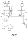
- the installation 1 according to the state of the art represented in the figure 1 is composed of a number of photovoltaic panels 2, including panels with reference 2a, 2b, ... 2n, which are for example mounted on the roof of a building.
- Each panel 2 is characterized by a voltage VDC between the positive terminal 3 and the negative terminal 4 of the panel 2, respectively the voltages VDCa, VDCb, ..., VDCn.
- the photovoltaic panels are connected together in series, that is to say that the negative terminal of a panel 2 is connected via an electrical wire 5 with the positive terminal of the next panel.
- the set of photovoltaic panels 2 connected in series is connected to a power cable 6 with two electric wires 7.
- This cable 6 is connected to an inverter 8 via a disconnector 9 which can isolate the inverter 8 from the power cable 6 by means of a handle 10.
- the inverter 8 is in turn connected to the electricity distribution network 11 via a circuit breaker board 12, which is provided with a handle 13 to be able to cut off the supply of the network 11.
- the power cable 6 is under a voltage VDC which is the sum of the voltages VDCa, VDCb, ... VDCn connected panels.
- the voltage on the cable 6 will be 180 Volt DC.
- the inverter 8 transforms the direct current coming from the power supply cable 6 into a AC current compatible with the standards of the network 11, for example 220 Volt AV, 50 Hz.
- the relatively high voltage on the power cable 6 poses a problem in the event of fire during the day since the cable 6 remains permanently under high voltage as the photovoltaic panels are exposed to daylight.
- the installation 14 according to the invention as represented in the figure 2 , comprises a security box 15 which comprises as many bipolar switches 16 as there are photovoltaic panels 2.
- the housing is preferably a sealed housing and the switches 16 are arbitrarily sealed in a resin.
- the photovoltaic panels 2 are connected to the input terminals of the switches 16 in such a way that each of the panels 2 is connected individually to one of the switches 16.
- the output terminals of the switches 17 are connected in series on the DC power cable 6 connected to the disconnector 9 and to the inverter 8 as before.
- the switches 17 are preferably normally open type relays as schematically represented in the figures 2 and 3 , at rest the contacts 17 between the inlet and the outlet are held in the open position by a return spring 18 as in the situation of the figure 3 .
- a safety disconnector 21 makes it possible to cut off the control signal 20 by means of a handle 22 for example in order to be able to open the relays 16 if necessary to isolate the panels 2 of the power cable 6.
- the safety disconnector 21 is preferably located at a location near the inverter 8 and therefore easily accessible for firefighters.
- the installation 14 is optionally provided with a display 23 for displaying the voltage on the DC power cable 6, this display 23 being preferably located near the circuit breaker board 12 of the network 11 and near the safety disconnector 21.
- the safety disconnector 21 is closed to switch the control signal 20 to the coil 19 of the relay-switches 16 to close the contacts 17 of the relays 16 as shown in the situation of the figure 2 .
- the voltage transferred by the cable 6 to the inverter 8 is exactly the same as in the conventional situation of the figure 1 , the panels 2 being connected in series in both cases.
- the fire-fighters can cut off the control signal 20 by actuating the handle 22 of the safety disconnector 22.
- Firefighters can also easily control the absence of any voltage on the display 23.
- the maximum voltage present in this part of the installation 14 is the maximum voltage of each of the panels.
- the maximum voltage is therefore 30 Volt DC, which poses no danger for the firefighters during the extinguishing work since these 30 Volt DC are sufficiently far from the danger threshold of 100 DC Volt.
- relay block with a single control coil 19 can be replaced by individual relays each with its own control coil.
- the control of the switches need not be a command as described, but can alternatively be replaced by manual control; by a remote control; by manual control; by automatic control by means of a fire detector or by means of a smoke detector; or by other types of command.
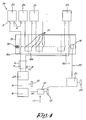
- the figure 4 shows an alternative connection of the photovoltaic panels on the input of the switches 16 of the housing 15.
- the photovoltaic panels 2a and 2b are grouped in series and connected as such on a single switch 2a, while the other panels 2 are always individually connected to the contactors 16. In this way we can save on the number of switches 16 .
- the resulting voltage of the panel group 2a and 2b on the contactor terminals is VDCa + VDCb, that is to say 60 Volt DC for panels of 30 Volt DC, while the voltage on the terminals of the other contactors 16 is 30 Volt DC.
- the maximum DC voltage in the installation will be 60 Volt DC, which is still far from the danger threshold of 100 Volt DC.
- the installer must look for a situation in which the maximum value of the DC voltage in the photovoltaic installation is 100 Volt DC, or better still 50 DC, or even better 30 Volt DC.
Abstract
Description
Installation photovoltaïque avec protection contre les dangers d'électrocution en cas d'incendie.Photovoltaic system with protection against the dangers of electrocution in case of fire.
Il est connu qu'une installation photovoltaïque comprend un nombre de panneaux photovoltaïques qui convertissent la lumière en électricité.It is known that a photovoltaic installation includes a number of photovoltaic panels that convert light into electricity.
Les installations photovoltaïques se font actuellement surtout sur les toits des logements ou des bâtiments, soit en intégration de toiture, soit en surimposition.Photovoltaic installations are currently mainly on the roofs of dwellings or buildings, either in roof integration or superimposed.
Chaque panneau photovoltaïque est caractérisé par une puissance électrique et une tension de sortie en courant continu, appelé aussi courant DC, typiquement une tension relativement basse, par exemple de 30 Volts.Each photovoltaic panel is characterized by an electric power and a DC output voltage, also called DC current, typically a relatively low voltage, for example 30 volts.
Les installations photovoltaïques sont généralement raccordées au réseau de distribution d'électricité.Photovoltaic installations are usually connected to the electricity distribution network.
Pour cela il est nécessaire de transformer le courant électrique continu, produit par l'ensemble des panneaux photovoltaïques, avec une tension relativement basse, aux normes du réseau, typiquement du 220 Volt à courant alternatif (courant AC) de 50 Hz.For this it is necessary to transform the continuous electric current, produced by all photovoltaic panels, with a relatively low voltage, to the standards of the network, typically 220 volt AC (AC current) of 50 Hz.
Cette transformation se fait au niveau de l'onduleur.This transformation is done at the level of the inverter.
Les panneaux photovoltaïques sont généralement connectés en série sur un câble électrique d'alimentation pour raccorder les panneaux photovoltaïque à l'onduleur.Photovoltaic panels are usually connected in series on an electrical supply cable to connect the photovoltaic panels to the inverter.
Si, par exemple, six panneaux de 30 Volts DC chacun sont connectés en série, le câble d'alimentation se trouve sous tension de 180 Volts DC, qui est une tension potentiellement dangereuse pour une personne en cas de contact avec les fils électrique du câble d'alimentation.If, for example, six panels of 30 Volts DC each are connected in series, the power cable is powered by 180 Volts DC, which is a potentially dangerous voltage for a person in case of contact with the electrical wires of the cable. power.
En termes générales, le risque d'une électrocution fatal est réel pour des tensions DC au dessus de 100 Volts.In general terms, the risk of fatal electrocution is real for DC voltages above 100 volts.
Pour autant que les panneaux photovoltaïques soient exposés à la lumière, les panneaux produisent de l'électricité et le câble d'alimentation reste sous tension, même si on coupe l'interrupteur central du tableau disjoncteur du réseau.As long as the photovoltaic panels are exposed to light, the panels produce electricity and the power cable remains energized, even if the central switch of the network breaker panel is cut.
En cas d'incendie cela représente une menace d'électrocution réelle pour les pompiers car il est bien connu que l'eau et l'électricité ne font pas bon ménage.In case of fire it represents a real threat of electrocution for firefighters because it is well known that water and electricity do not mix well.
Il suffit que l'eau ou l'échelle des pompiers touche un des fils du câble d'alimentation pour être électrocuté. Il n'y a d'ailleurs pas de sécurité pour couper le courant des panneaux photovoltaïques quand cela arrive puisque les panneaux restent actifs en permanence tant qu'ils sont exposés à la lumière.It is sufficient that the water or ladder of firefighters touches one of the wires of the power cable to be electrocuted. There is also no security to cut the power of photovoltaic panels when this happens since the panels remain permanently active as long as they are exposed to light.
Le danger est connu par les pompiers, même à ce point que certains pompiers pourraient refuser d'intervenir sur un bâtiment pourvu d'une installation photovoltaïque classique.The danger is known by firefighters, even to the point that some firefighters may refuse to intervene on a building equipped with a conventional photovoltaic installation.
L'invention a pour but d'éviter les inconvénients susdits et de procurer une installation photovoltaïque qui donne une plus grande sécurité aux pompiers.The object of the invention is to avoid the above-mentioned drawbacks and to provide a photovoltaic installation which gives greater security to the firefighters.
Ce but est atteint selon l'invention par une installation photovoltaïque classique comme décrit ci-avant mais dans laquelle les panneaux photovoltaïques sont connectés sur le câble d'alimentation DC par l'intermédiaire d'un nombre de commutateurs, soit d'une manière individuelle où chacun des panneaux est connecté sur le câble d'alimentation DC par l'intermédiaire d'un susdit commutateur, soit d'une manière groupée où les panneaux sont interconnectés en groupes, chaque groupe étant connecté sur le câble d'alimentation DC par l'intermédiaire d'un susdit commutateur, les groupes étant choisies de façon à ce que leur tension DC résultante ne dépasse pas une valeur maximale déterminée de façon à éviter tout danger d'électrocution pour un pompier pendant les travaux d'extinction, les commutateurs étant fermés en cas de fonctionnement normal de l'installation photovoltaïque et pouvant être coupés en cas d'incendie.This object is achieved according to the invention by a conventional photovoltaic installation as described above but in which the photovoltaic panels are connected to the DC supply cable via a number of switches, or individually where each of the panels is connected to the DC power cable via one of the above-mentioned switches, or in a grouped manner where the panels are interconnected in groups, each group being connected to the DC power cable by the intermediate of a said switch, the groups being chosen so that their resulting DC voltage does not exceed a maximum value determined so as to avoid any danger of electrocution for a firefighter during the extinguishing work, the switches being closed in the event of normal operation of the photovoltaic system and can be shut down in case of fire.
En cas d'un incendie, les pompiers peuvent couper les commutateurs pour isoler le câble d'alimentation DC des panneaux photovoltaïques.In the event of a fire, firefighters may switch off the switches to isolate the DC power cable from the PV panels.
Ainsi, le câble d'alimentation n'est plus sous tension et la tension DC maximale présente dans l'installation photovoltaïque est limitée à la tension DC d'un seul panneau photovoltaïque en cas d'un branchement individuelle ou à la tension DC résultante en cas d'un branchement par groupe de panneaux.Thus, the power cable is no longer powered and the maximum DC voltage present in the photovoltaic system is limited to the DC voltage of a single photovoltaic panel in the case of an individual connection or to the resulting DC voltage in case of a connection per group of panels.
De préférence les panneaux photovoltaïques sont connectés individuellement au câble d'alimentation par l'intermédiaire d'un susdit commutateur.Preferably the photovoltaic panels are individually connected to the power cable via a said switch.
La tension maximale est alors limitée à la tension maximale de chacun des panneaux individuels, qui est par exemple de 30 Volts DC et qui ne constitue pas de danger en cas d'une électrocution.The maximum voltage is then limited to the maximum voltage of each of the individual panels, which is for example 30 Volts DC and which does not constitute a danger in the event of an electrocution.
Les commutateurs sont préférentiellement des commutateurs bipolaire de façon à ce que les deux bornes + et - des panneaux puissent être isolées complètement du câble d'alimentation.The switches are preferably bipolar switches so that the two + and - terminals of the panels can be completely isolated from the power cable.
Les commutateurs sont de préférence des relais du type normalement ouvert qui sont reliés à un signal de commande pour fermer les relais en cas de fonctionnement normal de l'installation photovoltaïque, le signal de commande pouvant être coupé en cas d'incendie pour ouvrir les relais, par exemple par l'intermédiaire d'un sectionneur de sécurité situé tout près du tableau disjoncteur du réseau.The switches are preferably normally open type relays which are connected to a control signal for closing the relays in the event of normal operation of the photovoltaic system, the control signal being able to be switched off in the event of a fire to open the relays. eg via a safety disconnect located near the circuit breaker board.
L'avantage d'utiliser des relais normalement ouverts est que si le signal de commande est coupé par le feu, l'installation photovoltaïque se met automatiquement en sécurité.The advantage of using normally open relays is that if the control signal is cut off by the fire, the PV system automatically switches to security.
Selon une réalisation préférentielle, les commutateurs sont intégrés dans un boîtier étanche et éventuellement scellés dans une résine durcie pour protéger les commutateurs contre les intempéries et du vandalisme.In a preferred embodiment, the switches are embedded in a sealed housing and optionally sealed in a cured resin to protect the switches from the weather and vandalism.
L'installation photovoltaïque peut avantageusement être pourvue d'un afficheur pour afficher la tension présente sur le câble d'alimentation DC.The photovoltaic installation can advantageously be provided with a display for displaying the voltage present on the DC supply cable.
De ce fait les pompiers disposent d'un moyen de contrôle supplémentaire pour constater que réellement il n'y a plus de courant DC sur le câble d'alimentation.As a result firefighters have an additional control means to find that actually there is more DC current on the power cable.
L'invention concerne également un boîtier de sécurité pour une installation photovoltaïque comme décrite ci-avant qui comprend un nombre de relais du type normalement ouvert dont l'entrée de chacun de ces relais est pourvu pour le branchement individuel d'un panneau photovoltaïque ou d'un groupe de panneaux photovoltaïques à tension DC limitée à une valeur maximale et dont les sorties sont interconnectées en série et sont pourvues pour le branchement sur un câble d'alimentation DC et que les relais sont pourvus d'une connexion pour le branchement sur un signal de commande pour fermer les relais.The invention also relates to a security box for a photovoltaic installation as described above which comprises a number of normally open-type relays whose input of each of these relays is provided for the individual connection of a photovoltaic panel or a panel. a group of photovoltaic panels with DC voltage limited to a maximum value and whose outputs are interconnected in series and are provided for connection to a DC power cable and that the relays are provided with a connection for connection to a control signal to close the relays.
Pour plus de clarté, quelques exemples de réalisation d'une installation photovoltaïque selon l'invention sont décrits ci-après à titre illustratif et non restrictif, référence étant faite aux dessins annexés dans lesquels:
- La
figure 1 est un schéma électrique d'une installation photovoltaïque connue appartenant à l'état de la technique; - la
figure 2 représente un schéma d'une installation photovoltaïque selon l'invention dans un état normal de fonctionnement; - la
figure 3 montre le schéma de lafigure 2 dans un état mis en sécurité en cas d'incendie ; - la
figure 4 représente une autre réalisation d'une installation photovoltaïque selon l'invention.
- The
figure 1 is a circuit diagram of a known photovoltaic installation belonging to the state of the art; - the
figure 2 represents a diagram of a photovoltaic installation according to the invention in a normal state of operation; - the
figure 3 shows the diagram of thefigure 2 in a safe state in case of fire; - the
figure 4 represents another embodiment of a photovoltaic installation according to the invention.
L'installation 1 selon l'état de la technique représentée dans la
Quand les panneaux 2 sont exposés au soleil, la lumière captée par les panneaux 2 sera transformée en électricité.When the panels 2 are exposed to the sun, the light captured by the panels 2 will be transformed into electricity.
Chaque panneau 2 est caractérisé par une tension VDC entre la borne positive 3 et la borne négative 4 du panneau 2, respectivement les tensions VDCa, VDCb, ... , VDCn.Each panel 2 is characterized by a voltage VDC between the positive terminal 3 and the negative terminal 4 of the panel 2, respectively the voltages VDCa, VDCb, ..., VDCn.
Les panneaux photovoltaïques sont connectés entre eux en série, c'est-à-dire que la borne négative d'un panneau 2 est connectée via un fil électrique 5 avec la borne positive du panneau suivant.The photovoltaic panels are connected together in series, that is to say that the negative terminal of a panel 2 is connected via an
L'ensemble des panneaux photovoltaïques 2 connectés en série est connecté sur un câble d'alimentation 6 à deux fils électriques 7.The set of photovoltaic panels 2 connected in series is connected to a
Ce câble 6 est branché sur un onduleur 8 par l'intermédiaire d'un sectionneur 9 pouvant isoler l'onduleur 8 du câble d'alimentation 6 au moyen d'une poignée 10.This
L'onduleur 8 est branché à son tour sur le réseau de distribution d'électricité 11 par l'intermédiaire d'un tableau disjoncteur 12 du réseau, qui est muni d'une poignée 13 pour pouvoir couper l'alimentation du réseau 11.The
En vue de la connexion en série, le câble d'alimentation 6 se trouve sous une tension VDC qui est la somme des tensions VDCa, VDCb, ... VDCn des panneaux connectés.In view of the series connection, the
Dans le cas de six panneaux 2 à 30 Volt DC par exemple, la tension sur le câble 6 sera de 180 Volt DC.In the case of six panels 2 to 30 Volt DC for example, the voltage on the
L'onduleur 8 transforme le courant continu provenant du câble d'alimentation 6 en courant alternatif AC compatible aux normes du réseau 11, par exemple en 220 Volt AV, 50 Hz.The
La tension relativement élevée sur le câble d'alimentation 6 pose un problème en cas d'incendie pendant la journée puisque le câble 6 reste en permanence sous tension élevée tant que les panneaux photovoltaïques sont exposés à la lumière du jour.The relatively high voltage on the
Même si le sélectionneur 9 et le courant du réseau au niveau du tableau disjoncteur 12 sont coupés, une tension dangereusement élevée reste présent sur le câble 6.Even though the
Lorsque les pompiers aspergent l'installation photovoltaïque 1 pour l'extinction du feu, le risque est réel qu'un des jets d'eau touche les fils 7 et 8, avec des conséquences désastreuses pour au moins un des pompiers si la tension sur le câble d'alimentation 6 est plus élevée que 100 Volt DC, qui est pratiquement toujours le cas dans les installations connues jusqu'à présent.When firefighters spray the
L'installation 14 selon l'invention comme représentée dans la
Le boîtier est de préférence un boîtier étanche et les commutateurs 16 sont arbitrairement scellés dans une résine.The housing is preferably a sealed housing and the switches 16 are arbitrarily sealed in a resin.
Les panneaux photovoltaïques 2 sont connectés sur les bornes d'entrée des commutateurs 16 de telle façon à ce que chacun des panneaux 2 soit connecté d'une manière individuelle sur un des commutateurs 16.The photovoltaic panels 2 are connected to the input terminals of the switches 16 in such a way that each of the panels 2 is connected individually to one of the switches 16.
Les bornes de sortie des commutateurs 17 sont connectées en série sur le câble d'alimentation DC 6 connecté au sectionneur 9 et à l'onduleur 8 comme précédemment.The output terminals of the
Les commutateurs 17 sont de préférence des relais du type normalement ouvert comme représenté schématiquement dans les
Dans le cas représenté il s'agit plutôt d'un bloc de relais avec une seule bobine de commande 19 qui est reliée à un signal de commande 20 qui, dans ce cas, est pris du tableau disjoncteur 12 pour fermer les contacts 17 des relais-commutateurs 16.In the case shown it is rather a relay block with a
Un sectionneur de sécurité 21 permet de couper le signal de commande 20 au moyen d'une poignée 22 par exemple afin de pouvoir ouvrir les relais 16 en cas de besoin pour isoler les panneaux 2 du câble d'alimentation 6.A
Le sectionneur de sécurité 21 se trouve de préférence à un endroit près de l'onduleur 8 et donc facilement accessible pour les pompiers.The
L'installation 14 est optionnellement pourvue d'un afficheur 23 pour afficher la tension sur le câble d'alimentation DC 6, cet afficheur 23 étant situé de préférence près du tableau disjoncteur 12 du réseau 11 et près du sectionneur de sécurité 21.The
Le fonctionnement de l'installation est simple et comme suit.The operation of the installation is simple and as follows.
Dans son fonctionnement normal le sectionneur de sécurité 21 est fermé pour faire passer le signal de commande 20 à la bobine 19 des relais-commutateurs 16 pour fermer les contacts 17 des relais 16 comme représenté dans la situation de la
Dans cette situation les panneaux photovoltaïques sont branchés en série sur le câble d'alimentation 6 à travers les relais-commutateurs 16.In this situation the photovoltaic panels are connected in series on the
La tension transférée par le câble 6 à l'onduleur 8 est exactement le même que dans la situation classique de la
Pour six panneaux de 30 Volt DC il y aura donc une tension de 180 Volt DC sur le câble 6.For six panels of 30 Volt DC there will therefore be a voltage of 180 Volt DC on the
En cas d'incendie les pompiers peuvent couper le signal de commande 20 en actionnant la poignée 22 du sectionneur de sécurité 22.In the event of a fire, the fire-fighters can cut off the
Dans ce cas les contacts 17 sont ouverts par le ressort 18 comme représenté dans la
Il n'y a donc plus de courant DC sur le câble 6, même si les panneaux 2 sont toujours actifs par exposition à la lumière.There is therefore no DC current on the
Les pompiers peuvent d'ailleurs facilement contrôler l'absence de toute tension sur l'afficheur 23.Firefighters can also easily control the absence of any voltage on the
Du côté des entrées des commutateurs 16 tous les panneaux 2 sont isolés sur eux-mêmes, ce qui veut dire que la tension maximale présente dans cette partie de l'installation 14 est la tension maximale de chacun des panneaux. Dans le cas de panneaux identiques de 30 Volt DC, la tension maximale est donc de 30 Volt DC, ce qui ne pose aucun danger pour les pompiers pendant les travaux d'extinction puisque ces 30 Volt DC sont suffisamment éloignés du seuil de danger de 100 Volt DC.On the side of the inputs of the switches 16, all the panels 2 are isolated on themselves, which means that the maximum voltage present in this part of the
Il est évident que le rôle du sectionneur de sécurité 21 peut aussi être joué par le tableau disjoncteur 12.It is obvious that the role of the
Il est évident aussi que le bloc de relais avec une seule bobine de commande 19 peut être remplacé par des relais individuels chacun avec sa propre bobine de commande.It is also evident that the relay block with a
Au lieu d'utiliser des commutateurs bipolaires, il est possible aussi de remplacer chacun des commutateurs par deux relais unipolaires ou par un seul relais unipolaire pour couper uniquement le côté positif ou le côté négatif des panneaux.Instead of using bipolar switches, it is also possible to replace each of the switches with two unipolar relays or a single unipolar relay to cut only the positive or negative side of the panels.
A part des commutateurs du type relais il n'est pas exclus d'utiliser d'autres types de commutateurs.Besides switches of the relay type, it is not excluded to use other types of switches.
La commande des commutateurs ne doit pas nécessairement être une commande telle que décrite, mais peut alternativement être remplacée par une commande manuelle ; par une télécommande ; par une commande manuelle; par une commande automatique au moyen d'un détecteur d'incendie ou au moyen d'un détecteur de fumée; ou par encore d'autres types de commande.
La
The
Dans ce cas les panneaux photovoltaïques 2a et 2b sont regroupés en série et connectés comme tel sur un seul commutateur 2a, tandis que les autres panneaux 2 sont toujours connectés individuellement sur les contacteurs 16. De cette façon on peut économiser sur le nombre de commutateurs 16.In this case the
Dans ce cas la tension résultante du groupe de panneaux 2a et 2b sur les bornes du contacteur est de VDCa + VDCb, c'est-à-dire 60 Volt DC pour des panneaux de 30 Volt DC, tandis que la tension sur les bornes des autres contacteurs 16 est de 30 Volt DC.In this case the resulting voltage of the
Lorsque le sectionneur de sécurité 21 est coupé en cas d'incendie, la tension DC maximale dans l'installation sera de 60 Volt DC, ce qui est encore loin du seuil de danger de 100 Volt DC.When the
Pour la sécurité des pompiers il est évident qu'on doit rechercher à minimaliser la tension DC maximale dans l'installation 14 et donc de minimaliser de nombre de regroupement des panneaux en série et pour autant que possible de rechercher une connexion individuelle des panneaux 2.For the safety of firefighters it is obvious that we must seek to minimize the maximum DC voltage in the
De toute façon l'installateur doit rechercher une situation dans laquelle la valeur maximale de la tension DC dans l'installation photovoltaïque est de 100 Volt DC, ou mieux de 50 DC, ou mieux encore de 30 Volt DC.In any case, the installer must look for a situation in which the maximum value of the DC voltage in the photovoltaic installation is 100 Volt DC, or better still 50 DC, or even better 30 Volt DC.
Il est évident que l'invention n'est nullement limitée aux exemples décrits ci-avant mais que de nombreuses modifications peuvent être apportées à l'installation photovoltaïque selon l'invention sans sortir du cadre de l'invention.It is obvious that the invention is not limited to the examples described above, but that many modifications can be made to the photovoltaic system according to the invention without departing from the scope of the invention.
Claims (14)
Priority Applications (1)
| Application Number | Priority Date | Filing Date | Title |
|---|---|---|---|
| EP10010036A EP2432026A1 (en) | 2010-09-21 | 2010-09-21 | Photovoltaic plant with protection against the risks of electrocution in the event of a fire and safety box for such a plant |
Applications Claiming Priority (1)
| Application Number | Priority Date | Filing Date | Title |
|---|---|---|---|
| EP10010036A EP2432026A1 (en) | 2010-09-21 | 2010-09-21 | Photovoltaic plant with protection against the risks of electrocution in the event of a fire and safety box for such a plant |
Publications (1)
| Publication Number | Publication Date |
|---|---|
| EP2432026A1 true EP2432026A1 (en) | 2012-03-21 |
Family
ID=43825243
Family Applications (1)
| Application Number | Title | Priority Date | Filing Date |
|---|---|---|---|
| EP10010036A Withdrawn EP2432026A1 (en) | 2010-09-21 | 2010-09-21 | Photovoltaic plant with protection against the risks of electrocution in the event of a fire and safety box for such a plant |
Country Status (1)
| Country | Link |
|---|---|
| EP (1) | EP2432026A1 (en) |
Cited By (3)
| Publication number | Priority date | Publication date | Assignee | Title |
|---|---|---|---|---|
| FR3027749A1 (en) * | 2014-10-23 | 2016-04-29 | Patrice Georges Gaston Antoine Creuzot | DEVICE FOR ELECTRICALLY SECURING A INSTALLATION OF PHOTOVOLTAIC PANELS BY REDUCING THE ELECTRICAL VOLTAGES |
| JP2016135016A (en) * | 2015-01-20 | 2016-07-25 | 日東工業株式会社 | Photovoltaic power generation system |
| CN108867909A (en) * | 2018-08-09 | 2018-11-23 | 国家能源投资集团有限责任公司 | photovoltaic system |
Citations (8)
| Publication number | Priority date | Publication date | Assignee | Title |
|---|---|---|---|---|
| EP1039361A1 (en) * | 1999-03-24 | 2000-09-27 | Kaneka Corporation | Photovoltaic generation system, wiring apparatus for photovoltaic generation system, and wiring structure therefor |
| US20010023703A1 (en) * | 2000-02-29 | 2001-09-27 | Hiroshi Kondo | Solar power generation apparatus and control method therefor |
| DE202006007613U1 (en) * | 2006-05-11 | 2006-08-17 | Beck, Manfred | Photovoltaic system for production of electrical energy, has thermal fuse provided in connecting lines between photovoltaic unit and hand-over point, where fuse has preset marginal temperature corresponding to fire temperature |
| US20090207543A1 (en) * | 2008-02-14 | 2009-08-20 | Independent Power Systems, Inc. | System and method for fault detection and hazard prevention in photovoltaic source and output circuits |
| EP2101391A2 (en) * | 2008-03-13 | 2009-09-16 | Moeller GmbH | Protection device for solar panels |
| US20100139743A1 (en) * | 2009-07-30 | 2010-06-10 | Tigo Energy | Novel System and Method for Addressing Solar Energy Production Capacity Loss Due to Field Buildup Between Cells and Glass and Frame Assembly |
| US20100139734A1 (en) * | 2009-02-05 | 2010-06-10 | Tigo Energy | Systems and Methods for an Enhanced Watchdog in Solar Module Installations |
| WO2010078303A2 (en) * | 2008-12-29 | 2010-07-08 | Atonometrics, Inc. | Electrical safety shutoff system and devices for photovoltaic modules |
-
2010
- 2010-09-21 EP EP10010036A patent/EP2432026A1/en not_active Withdrawn
Patent Citations (8)
| Publication number | Priority date | Publication date | Assignee | Title |
|---|---|---|---|---|
| EP1039361A1 (en) * | 1999-03-24 | 2000-09-27 | Kaneka Corporation | Photovoltaic generation system, wiring apparatus for photovoltaic generation system, and wiring structure therefor |
| US20010023703A1 (en) * | 2000-02-29 | 2001-09-27 | Hiroshi Kondo | Solar power generation apparatus and control method therefor |
| DE202006007613U1 (en) * | 2006-05-11 | 2006-08-17 | Beck, Manfred | Photovoltaic system for production of electrical energy, has thermal fuse provided in connecting lines between photovoltaic unit and hand-over point, where fuse has preset marginal temperature corresponding to fire temperature |
| US20090207543A1 (en) * | 2008-02-14 | 2009-08-20 | Independent Power Systems, Inc. | System and method for fault detection and hazard prevention in photovoltaic source and output circuits |
| EP2101391A2 (en) * | 2008-03-13 | 2009-09-16 | Moeller GmbH | Protection device for solar panels |
| WO2010078303A2 (en) * | 2008-12-29 | 2010-07-08 | Atonometrics, Inc. | Electrical safety shutoff system and devices for photovoltaic modules |
| US20100139734A1 (en) * | 2009-02-05 | 2010-06-10 | Tigo Energy | Systems and Methods for an Enhanced Watchdog in Solar Module Installations |
| US20100139743A1 (en) * | 2009-07-30 | 2010-06-10 | Tigo Energy | Novel System and Method for Addressing Solar Energy Production Capacity Loss Due to Field Buildup Between Cells and Glass and Frame Assembly |
Cited By (3)
| Publication number | Priority date | Publication date | Assignee | Title |
|---|---|---|---|---|
| FR3027749A1 (en) * | 2014-10-23 | 2016-04-29 | Patrice Georges Gaston Antoine Creuzot | DEVICE FOR ELECTRICALLY SECURING A INSTALLATION OF PHOTOVOLTAIC PANELS BY REDUCING THE ELECTRICAL VOLTAGES |
| JP2016135016A (en) * | 2015-01-20 | 2016-07-25 | 日東工業株式会社 | Photovoltaic power generation system |
| CN108867909A (en) * | 2018-08-09 | 2018-11-23 | 国家能源投资集团有限责任公司 | photovoltaic system |
Similar Documents
| Publication | Publication Date | Title |
|---|---|---|
| EP2320535B1 (en) | Current-limiting circuit breaker, electrical distribution device equipped with such a limiting circuit breaker and current-limiting method | |
| EP1449287B1 (en) | Control and protection module of a switch apparatus | |
| EP2432026A1 (en) | Photovoltaic plant with protection against the risks of electrocution in the event of a fire and safety box for such a plant | |
| AU2011334598B2 (en) | A system for isolating portions of a power supply array | |
| EP2390981A1 (en) | Device for securing an electric power generation facility and method for implementing such a device | |
| WO2011135239A1 (en) | Safety device for photovoltaic panels | |
| FR2959063A1 (en) | Photovoltaic electric generator for generation of photovoltaic electricity on roof of e.g. building, has control module connected electrically to network and controlled opening of switch when module is not powered network | |
| FR2946797A1 (en) | Photovoltaic installation for distributing electricity to e.g. isolated sites, has photovoltaic cells comprising string with terminals, where potential difference of each terminal is less than predetermined safety threshold | |
| CH632093A5 (en) | EARTHING CONTROL CIRCUIT. | |
| FR2549287A1 (en) | Differential protective switch with neutral cable break protection | |
| EP3719947B1 (en) | Electrical protection methods and systems | |
| EP2887772B1 (en) | Lighting system with LEDs and remote luminaire | |
| JPH0993805A (en) | Disaster preventive circuit breaker and distribution board therewith | |
| EP2887769B1 (en) | Lighting system with LEDs and remote luminaire | |
| EP2774182A1 (en) | Photovoltaic panel safety device | |
| FR3130099A1 (en) | Electric device for converting a voltage and associated supply system | |
| EP3832687A1 (en) | Set of electrical protection devices with two levels that are connected in series | |
| BE898689A (en) | METHOD AND APPARATUS FOR AUTOMATICALLY LOCKING A LOAD DISCONNECTION SWITCH NEAR A LOCALIZED FAULT | |
| OA20466A (en) | Multifunction device for automatic lighting in the event of a power interruption and for reliable prevention of household appliances against lightning and fluctuations in the electric current | |
| EP3244505A1 (en) | Device for photovoltaic system security | |
| EP3621171A1 (en) | Electrical facility with quick redeployment | |
| FR2970375A1 (en) | System for controlling electric safety of e.g. person, intervening on energy producing facility providing power to e.g. enterprise, has control device attached with circuit to cut available power from circuit and to open another circuit | |
| FR2704698A1 (en) | Method for controlling the power supply to electrical equipment, modules for implementing this method, electrical installation equipped with these modules, and corresponding installation method | |
| ITMI20110982A1 (en) | SAFETY DEVICE FOR A PHOTOVOLTAIC SYSTEM | |
| WO2001013193A1 (en) | Electric power supply network, in particular for public lighting |
Legal Events
| Date | Code | Title | Description |
|---|---|---|---|
| PUAI | Public reference made under article 153(3) epc to a published international application that has entered the european phase |
Free format text: ORIGINAL CODE: 0009012 |
|
| 17P | Request for examination filed |
Effective date: 20111011 |
|
| AK | Designated contracting states |
Kind code of ref document: A1 Designated state(s): AL AT BE BG CH CY CZ DE DK EE ES FI FR GB GR HR HU IE IS IT LI LT LU LV MC MK MT NL NO PL PT RO SE SI SK SM TR |
|
| AX | Request for extension of the european patent |
Extension state: BA ME RS |
|
| STAA | Information on the status of an ep patent application or granted ep patent |
Free format text: STATUS: THE APPLICATION IS DEEMED TO BE WITHDRAWN |
|
| 18D | Application deemed to be withdrawn |
Effective date: 20130403 |
|
| RAP1 | Party data changed (applicant data changed or rights of an application transferred) |
Owner name: MS ENERGIES SOCIETE PRIVEE A RESPONSABILITE LIMITE |
|
| 19U | Interruption of proceedings before grant |
Effective date: 20130513 |
|
| 19W | Proceedings resumed before grant after interruption of proceedings |
Effective date: 20210901 |
|
| PUAJ | Public notification under rule 129 epc |
Free format text: ORIGINAL CODE: 0009425 |
|
| 32PN | Public notification |
Free format text: NOTIFICATION ETABLIE CONFORMEMENT A LA REGLE 142 CBE (REPRISE DE LA PROCEDURE CONFORMEMENT A LA REGLE 142 (2) CBE EN DATE DU 17.03.2021) |
|
| STAA | Information on the status of an ep patent application or granted ep patent |
Free format text: STATUS: THE APPLICATION IS DEEMED TO BE WITHDRAWN |
|
| PUAJ | Public notification under rule 129 epc |
Free format text: ORIGINAL CODE: 0009425 |
|
| 32PN | Public notification |
Free format text: CONSTATATION DE LA PERTE D'UN DROIT CONFORMEMENT A LA REGLE 112(1) CBE (OEB FORM 2524 EN DATE DU 21/07/2022) |
|
| R18D | Application deemed to be withdrawn (corrected) |
Effective date: 20220302 |