EP2431213A1 - Vehicle charging unit - Google Patents
Vehicle charging unit Download PDFInfo
- Publication number
- EP2431213A1 EP2431213A1 EP09844621A EP09844621A EP2431213A1 EP 2431213 A1 EP2431213 A1 EP 2431213A1 EP 09844621 A EP09844621 A EP 09844621A EP 09844621 A EP09844621 A EP 09844621A EP 2431213 A1 EP2431213 A1 EP 2431213A1
- Authority
- EP
- European Patent Office
- Prior art keywords
- rectification unit
- power reception
- unit
- charger
- rectification
- Prior art date
- Legal status (The legal status is an assumption and is not a legal conclusion. Google has not performed a legal analysis and makes no representation as to the accuracy of the status listed.)
- Granted
Links
Images







Classifications
-
- B—PERFORMING OPERATIONS; TRANSPORTING
- B60—VEHICLES IN GENERAL
- B60L—PROPULSION OF ELECTRICALLY-PROPELLED VEHICLES; SUPPLYING ELECTRIC POWER FOR AUXILIARY EQUIPMENT OF ELECTRICALLY-PROPELLED VEHICLES; ELECTRODYNAMIC BRAKE SYSTEMS FOR VEHICLES IN GENERAL; MAGNETIC SUSPENSION OR LEVITATION FOR VEHICLES; MONITORING OPERATING VARIABLES OF ELECTRICALLY-PROPELLED VEHICLES; ELECTRIC SAFETY DEVICES FOR ELECTRICALLY-PROPELLED VEHICLES
- B60L53/00—Methods of charging batteries, specially adapted for electric vehicles; Charging stations or on-board charging equipment therefor; Exchange of energy storage elements in electric vehicles
- B60L53/10—Methods of charging batteries, specially adapted for electric vehicles; Charging stations or on-board charging equipment therefor; Exchange of energy storage elements in electric vehicles characterised by the energy transfer between the charging station and the vehicle
- B60L53/12—Inductive energy transfer
-
- B—PERFORMING OPERATIONS; TRANSPORTING
- B60—VEHICLES IN GENERAL
- B60L—PROPULSION OF ELECTRICALLY-PROPELLED VEHICLES; SUPPLYING ELECTRIC POWER FOR AUXILIARY EQUIPMENT OF ELECTRICALLY-PROPELLED VEHICLES; ELECTRODYNAMIC BRAKE SYSTEMS FOR VEHICLES IN GENERAL; MAGNETIC SUSPENSION OR LEVITATION FOR VEHICLES; MONITORING OPERATING VARIABLES OF ELECTRICALLY-PROPELLED VEHICLES; ELECTRIC SAFETY DEVICES FOR ELECTRICALLY-PROPELLED VEHICLES
- B60L50/00—Electric propulsion with power supplied within the vehicle
- B60L50/10—Electric propulsion with power supplied within the vehicle using propulsion power supplied by engine-driven generators, e.g. generators driven by combustion engines
- B60L50/16—Electric propulsion with power supplied within the vehicle using propulsion power supplied by engine-driven generators, e.g. generators driven by combustion engines with provision for separate direct mechanical propulsion
-
- B—PERFORMING OPERATIONS; TRANSPORTING
- B60—VEHICLES IN GENERAL
- B60L—PROPULSION OF ELECTRICALLY-PROPELLED VEHICLES; SUPPLYING ELECTRIC POWER FOR AUXILIARY EQUIPMENT OF ELECTRICALLY-PROPELLED VEHICLES; ELECTRODYNAMIC BRAKE SYSTEMS FOR VEHICLES IN GENERAL; MAGNETIC SUSPENSION OR LEVITATION FOR VEHICLES; MONITORING OPERATING VARIABLES OF ELECTRICALLY-PROPELLED VEHICLES; ELECTRIC SAFETY DEVICES FOR ELECTRICALLY-PROPELLED VEHICLES
- B60L50/00—Electric propulsion with power supplied within the vehicle
- B60L50/50—Electric propulsion with power supplied within the vehicle using propulsion power supplied by batteries or fuel cells
- B60L50/60—Electric propulsion with power supplied within the vehicle using propulsion power supplied by batteries or fuel cells using power supplied by batteries
- B60L50/61—Electric propulsion with power supplied within the vehicle using propulsion power supplied by batteries or fuel cells using power supplied by batteries by batteries charged by engine-driven generators, e.g. series hybrid electric vehicles
-
- B—PERFORMING OPERATIONS; TRANSPORTING
- B60—VEHICLES IN GENERAL
- B60L—PROPULSION OF ELECTRICALLY-PROPELLED VEHICLES; SUPPLYING ELECTRIC POWER FOR AUXILIARY EQUIPMENT OF ELECTRICALLY-PROPELLED VEHICLES; ELECTRODYNAMIC BRAKE SYSTEMS FOR VEHICLES IN GENERAL; MAGNETIC SUSPENSION OR LEVITATION FOR VEHICLES; MONITORING OPERATING VARIABLES OF ELECTRICALLY-PROPELLED VEHICLES; ELECTRIC SAFETY DEVICES FOR ELECTRICALLY-PROPELLED VEHICLES
- B60L53/00—Methods of charging batteries, specially adapted for electric vehicles; Charging stations or on-board charging equipment therefor; Exchange of energy storage elements in electric vehicles
- B60L53/10—Methods of charging batteries, specially adapted for electric vehicles; Charging stations or on-board charging equipment therefor; Exchange of energy storage elements in electric vehicles characterised by the energy transfer between the charging station and the vehicle
- B60L53/12—Inductive energy transfer
- B60L53/122—Circuits or methods for driving the primary coil, e.g. supplying electric power to the coil
-
- B—PERFORMING OPERATIONS; TRANSPORTING
- B60—VEHICLES IN GENERAL
- B60L—PROPULSION OF ELECTRICALLY-PROPELLED VEHICLES; SUPPLYING ELECTRIC POWER FOR AUXILIARY EQUIPMENT OF ELECTRICALLY-PROPELLED VEHICLES; ELECTRODYNAMIC BRAKE SYSTEMS FOR VEHICLES IN GENERAL; MAGNETIC SUSPENSION OR LEVITATION FOR VEHICLES; MONITORING OPERATING VARIABLES OF ELECTRICALLY-PROPELLED VEHICLES; ELECTRIC SAFETY DEVICES FOR ELECTRICALLY-PROPELLED VEHICLES
- B60L53/00—Methods of charging batteries, specially adapted for electric vehicles; Charging stations or on-board charging equipment therefor; Exchange of energy storage elements in electric vehicles
- B60L53/10—Methods of charging batteries, specially adapted for electric vehicles; Charging stations or on-board charging equipment therefor; Exchange of energy storage elements in electric vehicles characterised by the energy transfer between the charging station and the vehicle
- B60L53/14—Conductive energy transfer
-
- B—PERFORMING OPERATIONS; TRANSPORTING
- B60—VEHICLES IN GENERAL
- B60L—PROPULSION OF ELECTRICALLY-PROPELLED VEHICLES; SUPPLYING ELECTRIC POWER FOR AUXILIARY EQUIPMENT OF ELECTRICALLY-PROPELLED VEHICLES; ELECTRODYNAMIC BRAKE SYSTEMS FOR VEHICLES IN GENERAL; MAGNETIC SUSPENSION OR LEVITATION FOR VEHICLES; MONITORING OPERATING VARIABLES OF ELECTRICALLY-PROPELLED VEHICLES; ELECTRIC SAFETY DEVICES FOR ELECTRICALLY-PROPELLED VEHICLES
- B60L53/00—Methods of charging batteries, specially adapted for electric vehicles; Charging stations or on-board charging equipment therefor; Exchange of energy storage elements in electric vehicles
- B60L53/20—Methods of charging batteries, specially adapted for electric vehicles; Charging stations or on-board charging equipment therefor; Exchange of energy storage elements in electric vehicles characterised by converters located in the vehicle
- B60L53/22—Constructional details or arrangements of charging converters specially adapted for charging electric vehicles
-
- B—PERFORMING OPERATIONS; TRANSPORTING
- B60—VEHICLES IN GENERAL
- B60L—PROPULSION OF ELECTRICALLY-PROPELLED VEHICLES; SUPPLYING ELECTRIC POWER FOR AUXILIARY EQUIPMENT OF ELECTRICALLY-PROPELLED VEHICLES; ELECTRODYNAMIC BRAKE SYSTEMS FOR VEHICLES IN GENERAL; MAGNETIC SUSPENSION OR LEVITATION FOR VEHICLES; MONITORING OPERATING VARIABLES OF ELECTRICALLY-PROPELLED VEHICLES; ELECTRIC SAFETY DEVICES FOR ELECTRICALLY-PROPELLED VEHICLES
- B60L53/00—Methods of charging batteries, specially adapted for electric vehicles; Charging stations or on-board charging equipment therefor; Exchange of energy storage elements in electric vehicles
- B60L53/30—Constructional details of charging stations
- B60L53/31—Charging columns specially adapted for electric vehicles
-
- H—ELECTRICITY
- H02—GENERATION; CONVERSION OR DISTRIBUTION OF ELECTRIC POWER
- H02J—ELECTRIC POWER NETWORKS; CIRCUIT ARRANGEMENTS OR SYSTEMS FOR SUPPLYING OR DISTRIBUTING ELECTRIC POWER; SYSTEMS FOR STORING ELECTRIC ENERGY
- H02J50/00—Circuit arrangements or systems for wireless supply or distribution of electric power
- H02J50/10—Circuit arrangements or systems for wireless supply or distribution of electric power using inductive coupling
- H02J50/12—Circuit arrangements or systems for wireless supply or distribution of electric power using inductive coupling of the resonant type
-
- B—PERFORMING OPERATIONS; TRANSPORTING
- B60—VEHICLES IN GENERAL
- B60L—PROPULSION OF ELECTRICALLY-PROPELLED VEHICLES; SUPPLYING ELECTRIC POWER FOR AUXILIARY EQUIPMENT OF ELECTRICALLY-PROPELLED VEHICLES; ELECTRODYNAMIC BRAKE SYSTEMS FOR VEHICLES IN GENERAL; MAGNETIC SUSPENSION OR LEVITATION FOR VEHICLES; MONITORING OPERATING VARIABLES OF ELECTRICALLY-PROPELLED VEHICLES; ELECTRIC SAFETY DEVICES FOR ELECTRICALLY-PROPELLED VEHICLES
- B60L2210/00—Converter types
- B60L2210/10—DC to DC converters
-
- B—PERFORMING OPERATIONS; TRANSPORTING
- B60—VEHICLES IN GENERAL
- B60L—PROPULSION OF ELECTRICALLY-PROPELLED VEHICLES; SUPPLYING ELECTRIC POWER FOR AUXILIARY EQUIPMENT OF ELECTRICALLY-PROPELLED VEHICLES; ELECTRODYNAMIC BRAKE SYSTEMS FOR VEHICLES IN GENERAL; MAGNETIC SUSPENSION OR LEVITATION FOR VEHICLES; MONITORING OPERATING VARIABLES OF ELECTRICALLY-PROPELLED VEHICLES; ELECTRIC SAFETY DEVICES FOR ELECTRICALLY-PROPELLED VEHICLES
- B60L2210/00—Converter types
- B60L2210/10—DC to DC converters
- B60L2210/12—Buck converters
-
- B—PERFORMING OPERATIONS; TRANSPORTING
- B60—VEHICLES IN GENERAL
- B60L—PROPULSION OF ELECTRICALLY-PROPELLED VEHICLES; SUPPLYING ELECTRIC POWER FOR AUXILIARY EQUIPMENT OF ELECTRICALLY-PROPELLED VEHICLES; ELECTRODYNAMIC BRAKE SYSTEMS FOR VEHICLES IN GENERAL; MAGNETIC SUSPENSION OR LEVITATION FOR VEHICLES; MONITORING OPERATING VARIABLES OF ELECTRICALLY-PROPELLED VEHICLES; ELECTRIC SAFETY DEVICES FOR ELECTRICALLY-PROPELLED VEHICLES
- B60L2210/00—Converter types
- B60L2210/10—DC to DC converters
- B60L2210/14—Boost converters
-
- B—PERFORMING OPERATIONS; TRANSPORTING
- B60—VEHICLES IN GENERAL
- B60L—PROPULSION OF ELECTRICALLY-PROPELLED VEHICLES; SUPPLYING ELECTRIC POWER FOR AUXILIARY EQUIPMENT OF ELECTRICALLY-PROPELLED VEHICLES; ELECTRODYNAMIC BRAKE SYSTEMS FOR VEHICLES IN GENERAL; MAGNETIC SUSPENSION OR LEVITATION FOR VEHICLES; MONITORING OPERATING VARIABLES OF ELECTRICALLY-PROPELLED VEHICLES; ELECTRIC SAFETY DEVICES FOR ELECTRICALLY-PROPELLED VEHICLES
- B60L2210/00—Converter types
- B60L2210/30—AC to DC converters
-
- B—PERFORMING OPERATIONS; TRANSPORTING
- B60—VEHICLES IN GENERAL
- B60L—PROPULSION OF ELECTRICALLY-PROPELLED VEHICLES; SUPPLYING ELECTRIC POWER FOR AUXILIARY EQUIPMENT OF ELECTRICALLY-PROPELLED VEHICLES; ELECTRODYNAMIC BRAKE SYSTEMS FOR VEHICLES IN GENERAL; MAGNETIC SUSPENSION OR LEVITATION FOR VEHICLES; MONITORING OPERATING VARIABLES OF ELECTRICALLY-PROPELLED VEHICLES; ELECTRIC SAFETY DEVICES FOR ELECTRICALLY-PROPELLED VEHICLES
- B60L2210/00—Converter types
- B60L2210/40—DC to AC converters
-
- B—PERFORMING OPERATIONS; TRANSPORTING
- B60—VEHICLES IN GENERAL
- B60L—PROPULSION OF ELECTRICALLY-PROPELLED VEHICLES; SUPPLYING ELECTRIC POWER FOR AUXILIARY EQUIPMENT OF ELECTRICALLY-PROPELLED VEHICLES; ELECTRODYNAMIC BRAKE SYSTEMS FOR VEHICLES IN GENERAL; MAGNETIC SUSPENSION OR LEVITATION FOR VEHICLES; MONITORING OPERATING VARIABLES OF ELECTRICALLY-PROPELLED VEHICLES; ELECTRIC SAFETY DEVICES FOR ELECTRICALLY-PROPELLED VEHICLES
- B60L2220/00—Electrical machine types; Structures or applications thereof
- B60L2220/10—Electrical machine types
- B60L2220/14—Synchronous machines
-
- B—PERFORMING OPERATIONS; TRANSPORTING
- B60—VEHICLES IN GENERAL
- B60Y—INDEXING SCHEME RELATING TO ASPECTS CROSS-CUTTING VEHICLE TECHNOLOGY
- B60Y2200/00—Type of vehicle
- B60Y2200/90—Vehicles comprising electric prime movers
- B60Y2200/91—Electric vehicles
-
- B—PERFORMING OPERATIONS; TRANSPORTING
- B60—VEHICLES IN GENERAL
- B60Y—INDEXING SCHEME RELATING TO ASPECTS CROSS-CUTTING VEHICLE TECHNOLOGY
- B60Y2200/00—Type of vehicle
- B60Y2200/90—Vehicles comprising electric prime movers
- B60Y2200/92—Hybrid vehicles
-
- H—ELECTRICITY
- H02—GENERATION; CONVERSION OR DISTRIBUTION OF ELECTRIC POWER
- H02J—ELECTRIC POWER NETWORKS; CIRCUIT ARRANGEMENTS OR SYSTEMS FOR SUPPLYING OR DISTRIBUTING ELECTRIC POWER; SYSTEMS FOR STORING ELECTRIC ENERGY
- H02J2105/00—Networks for supplying or distributing electric power characterised by their spatial reach or by the load
- H02J2105/30—Networks for supplying or distributing electric power characterised by their spatial reach or by the load the load networks being external to vehicles, i.e. exchanging power with vehicles
- H02J2105/33—Networks for supplying or distributing electric power characterised by their spatial reach or by the load the load networks being external to vehicles, i.e. exchanging power with vehicles exchanging power with road vehicles
- H02J2105/37—Networks for supplying or distributing electric power characterised by their spatial reach or by the load the load networks being external to vehicles, i.e. exchanging power with vehicles exchanging power with road vehicles exchanging power with electric vehicles [EV] or with hybrid electric vehicles [HEV]
-
- H—ELECTRICITY
- H02—GENERATION; CONVERSION OR DISTRIBUTION OF ELECTRIC POWER
- H02M—APPARATUS FOR CONVERSION BETWEEN AC AND AC, BETWEEN AC AND DC, OR BETWEEN DC AND DC, AND FOR USE WITH MAINS OR SIMILAR POWER SUPPLY SYSTEMS; CONVERSION OF DC OR AC INPUT POWER INTO SURGE OUTPUT POWER; CONTROL OR REGULATION THEREOF
- H02M1/00—Details of apparatus for conversion
- H02M1/0083—Converters characterised by their input or output configuration
- H02M1/0085—Partially controlled bridges
-
- Y—GENERAL TAGGING OF NEW TECHNOLOGICAL DEVELOPMENTS; GENERAL TAGGING OF CROSS-SECTIONAL TECHNOLOGIES SPANNING OVER SEVERAL SECTIONS OF THE IPC; TECHNICAL SUBJECTS COVERED BY FORMER USPC CROSS-REFERENCE ART COLLECTIONS [XRACs] AND DIGESTS
- Y02—TECHNOLOGIES OR APPLICATIONS FOR MITIGATION OR ADAPTATION AGAINST CLIMATE CHANGE
- Y02T—CLIMATE CHANGE MITIGATION TECHNOLOGIES RELATED TO TRANSPORTATION
- Y02T10/00—Road transport of goods or passengers
- Y02T10/60—Other road transportation technologies with climate change mitigation effect
- Y02T10/62—Hybrid vehicles
-
- Y—GENERAL TAGGING OF NEW TECHNOLOGICAL DEVELOPMENTS; GENERAL TAGGING OF CROSS-SECTIONAL TECHNOLOGIES SPANNING OVER SEVERAL SECTIONS OF THE IPC; TECHNICAL SUBJECTS COVERED BY FORMER USPC CROSS-REFERENCE ART COLLECTIONS [XRACs] AND DIGESTS
- Y02—TECHNOLOGIES OR APPLICATIONS FOR MITIGATION OR ADAPTATION AGAINST CLIMATE CHANGE
- Y02T—CLIMATE CHANGE MITIGATION TECHNOLOGIES RELATED TO TRANSPORTATION
- Y02T10/00—Road transport of goods or passengers
- Y02T10/60—Other road transportation technologies with climate change mitigation effect
- Y02T10/70—Energy storage systems for electromobility, e.g. batteries
-
- Y—GENERAL TAGGING OF NEW TECHNOLOGICAL DEVELOPMENTS; GENERAL TAGGING OF CROSS-SECTIONAL TECHNOLOGIES SPANNING OVER SEVERAL SECTIONS OF THE IPC; TECHNICAL SUBJECTS COVERED BY FORMER USPC CROSS-REFERENCE ART COLLECTIONS [XRACs] AND DIGESTS
- Y02—TECHNOLOGIES OR APPLICATIONS FOR MITIGATION OR ADAPTATION AGAINST CLIMATE CHANGE
- Y02T—CLIMATE CHANGE MITIGATION TECHNOLOGIES RELATED TO TRANSPORTATION
- Y02T10/00—Road transport of goods or passengers
- Y02T10/60—Other road transportation technologies with climate change mitigation effect
- Y02T10/7072—Electromobility specific charging systems or methods for batteries, ultracapacitors, supercapacitors or double-layer capacitors
-
- Y—GENERAL TAGGING OF NEW TECHNOLOGICAL DEVELOPMENTS; GENERAL TAGGING OF CROSS-SECTIONAL TECHNOLOGIES SPANNING OVER SEVERAL SECTIONS OF THE IPC; TECHNICAL SUBJECTS COVERED BY FORMER USPC CROSS-REFERENCE ART COLLECTIONS [XRACs] AND DIGESTS
- Y02—TECHNOLOGIES OR APPLICATIONS FOR MITIGATION OR ADAPTATION AGAINST CLIMATE CHANGE
- Y02T—CLIMATE CHANGE MITIGATION TECHNOLOGIES RELATED TO TRANSPORTATION
- Y02T10/00—Road transport of goods or passengers
- Y02T10/60—Other road transportation technologies with climate change mitigation effect
- Y02T10/72—Electric energy management in electromobility
-
- Y—GENERAL TAGGING OF NEW TECHNOLOGICAL DEVELOPMENTS; GENERAL TAGGING OF CROSS-SECTIONAL TECHNOLOGIES SPANNING OVER SEVERAL SECTIONS OF THE IPC; TECHNICAL SUBJECTS COVERED BY FORMER USPC CROSS-REFERENCE ART COLLECTIONS [XRACs] AND DIGESTS
- Y02—TECHNOLOGIES OR APPLICATIONS FOR MITIGATION OR ADAPTATION AGAINST CLIMATE CHANGE
- Y02T—CLIMATE CHANGE MITIGATION TECHNOLOGIES RELATED TO TRANSPORTATION
- Y02T90/00—Enabling technologies or technologies with a potential or indirect contribution to GHG emissions mitigation
- Y02T90/10—Technologies relating to charging of electric vehicles
- Y02T90/12—Electric charging stations
-
- Y—GENERAL TAGGING OF NEW TECHNOLOGICAL DEVELOPMENTS; GENERAL TAGGING OF CROSS-SECTIONAL TECHNOLOGIES SPANNING OVER SEVERAL SECTIONS OF THE IPC; TECHNICAL SUBJECTS COVERED BY FORMER USPC CROSS-REFERENCE ART COLLECTIONS [XRACs] AND DIGESTS
- Y02—TECHNOLOGIES OR APPLICATIONS FOR MITIGATION OR ADAPTATION AGAINST CLIMATE CHANGE
- Y02T—CLIMATE CHANGE MITIGATION TECHNOLOGIES RELATED TO TRANSPORTATION
- Y02T90/00—Enabling technologies or technologies with a potential or indirect contribution to GHG emissions mitigation
- Y02T90/10—Technologies relating to charging of electric vehicles
- Y02T90/14—Plug-in electric vehicles
Definitions
- the present invention relates to a vehicle charging apparatus, and particularly to a vehicle charging apparatus for charging a power storage device mounted on a vehicle by an AC power supply external to the vehicle.
- Japanese Patent Laying-Open No. 2008-220130 discloses a power supply system for a vehicle capable of charging a power storage unit such as a secondary battery and an electric double layer capacitor by a power supply external to the vehicle.
- This power supply system for a vehicle includes: conductive charging means for charging (conductively charging) the power storage unit by receiving and transmitting electric power with the power supply system electrically connected to the power supply external to the vehicle; inductive charging means for charging (inductively charging) the power storage unit by receiving and transmitting electric power with the power supply system magnetically coupled to the power supply external to the vehicle; and a charging control device selecting either the conductive charging means or the inductive charging means.
- a selection can be made between conductive charging with the conductive charging means and inductive charging with the inductive charging means to charge the power storage unit, and thus, an area where the power storage unit can be charged can be expanded (see PTL 1).
- the power supply system for a vehicle disclosed in above-mentioned Japanese Patent Laying-Open No. 2008-220130 is useful because the area where the power storage unit can be charged can be expanded.
- a charger for the conductive charging method so-called plug-in method
- a charger for the inductive charging method non-contact method
- an object of the present invention is to provide a vehicle charging apparatus that allows both conductive charging (plug-in charging) and inductive charging (non-contact charging) and can suppress an increase in cost.
- a vehicle charging apparatus is a vehicle charging apparatus for charging a power storage device mounted on a vehicle by an AC power supply external to the vehicle, including: a power reception terminal, a charger and a non-contact power reception unit.
- the power reception terminal is configured to be electrically connectable to the AC power supply.
- the charger is configured to convert AC electric power inputted from the power reception terminal to a predetermined DC voltage.
- the non-contact power reception unit is configured to be magnetically coupled to a power transmission unit of the AC power supply to receive electric power from the AC power supply in a non-contact manner.
- the non-contact power reception unit is connected to a power conversion circuit of the charger.
- the charger includes first and second rectification units, an inverter and an insulating transformer.
- the first rectification unit is configured to be capable of rectifying the AC electric power inputted from the power reception terminal.
- the inverter is connected to the first rectification unit.
- the insulating transformer is connected to the inverter.
- the second rectification unit is configured to rectify an output of the insulating transformer.
- the non-contact power reception unit is connected to either the first rectification unit or the second rectification unit.
- one rectification unit of the first and second rectification units is formed of a rectification element having more excellent high-frequency rectification property than that of a rectification element constituting the other rectification unit.
- the non-contact power reception unit is connected to the one rectification unit.
- the non-contact power reception unit is connected to the second rectification unit.
- the vehicle charging apparatus further includes a voltage conversion device. The voltage conversion device is provided between the non-contact power reception unit and the second rectification unit.
- the charger includes first and second rectification units, an inverter and an insulating transformer.
- the first rectification unit is configured to be capable of rectifying the AC electric power inputted from the power reception terminal.
- the inverter is connected to the first rectification unit.
- the insulating transformer is connected to the inverter.
- the second rectification unit is configured to rectify an output of the insulating transformer.
- the non-contact power reception unit includes a power reception coil and a third rectification unit.
- the power reception coil is configured to be magnetically coupled to a power transmission coil provided at the power transmission unit.
- the third rectification unit is configured to rectify an output of the power reception coil.
- the third rectification unit is connected between the first rectification unit and the inverter.
- the charger includes first and second rectification units, an inverter and an insulating transformer.
- the first rectification unit is configured to be capable of rectifying the AC electric power inputted from the power reception terminal.
- the inverter is connected to the first rectification unit.
- the insulating transformer is connected to the inverter.
- the second rectification unit is configured to rectify an output of the insulating transformer.
- the non-contact power reception unit includes a power reception coil and a third rectification unit.
- the power reception coil is configured to be magnetically coupled to a power transmission coil provided at the power transmission unit.
- the third rectification unit is configured to rectify an output of the power reception coil.
- the second rectification unit includes first and second upper-and-lower arms.
- the first and second upper-and-lower arms are connected in parallel between a positive electrode output line and a negative electrode output line of the charger.
- Each arm of the first upper-and-lower arm includes a switching element.
- a secondary coil of the insulating transformer is connected between an intermediate point of the first upper-and-lower arm and an intermediate point of the second upper-and-lower arm.
- the charger further includes a reactor. The reactor is connected between the intermediate point of the first upper-and-lower arm and the positive electrode output line.
- the third rectification unit is connected to the positive electrode output line and the negative electrode output line of the charger.
- the charger includes first and second rectification units, an inverter and an insulating transformer.
- the first rectification unit is configured to be capable of rectifying the AC electric power inputted from the power reception terminal.
- the inverter is connected to the first rectification unit.
- the insulating transformer is connected to the inverter.
- the second rectification unit is configured to rectify an output of the insulating transformer.
- the non-contact power reception unit includes a power reception coil and a third rectification unit.
- the power reception coil is configured to be magnetically coupled to a power transmission coil provided at the power transmission unit.
- the third rectification unit is configured to rectify an output of the power reception coil.
- the second rectification unit includes first and second upper-and-lower arms.
- the first and second upper-and-lower arms are connected in parallel between a positive electrode output line and a negative electrode output line of the charger.
- Each arm of the first upper-and-lower arm includes a switching element.
- a secondary coil of the insulating transformer is connected between an intermediate point of the first upper-and-lower arm and an intermediate point of the second upper-and-lower arm.
- the charger further includes a reactor. The reactor is connected between one output end of the third rectification unit and the intermediate point of the first upper-and-lower arm. The other output end of the third rectification unit is connected to the negative electrode output line of the charger.
- the charger includes first and second rectification units, an inverter and an insulating transformer.
- the first rectification unit is configured to be capable of rectifying the AC electric power inputted from the power reception terminal.
- the inverter is connected to the first rectification unit.
- the insulating transformer is connected to the inverter.
- the second rectification unit is configured to rectify an output of the insulating transformer.
- the non-contact power reception unit includes a power reception coil and a third rectification unit.
- the power reception coil is configured to be magnetically coupled to a power transmission coil provided at the power transmission unit.
- the third rectification unit is configured to rectify an output of the power reception coil.
- the second rectification unit includes first and second upper-and-lower arms.
- the first and second upper-and-lower arms are connected in parallel between a positive electrode output line and a negative electrode output line of the charger.
- Each arm of the first upper-and-lower arm includes a switching element.
- a secondary coil of the insulating transformer is connected between an intermediate point of the first upper-and-lower arm and an intermediate point of the second upper-and-lower arm.
- the third rectification unit is connected to the positive electrode output line and the negative electrode output line of the charger.
- the charger further includes a switching device. The switching device breaks electrical connection between the secondary coil of the insulating transformer and the intermediate point of the second upper-and-lower arm, and electrically connects the secondary coil to the positive electrode output line, when the non-contact power reception unit is used for charging.
- the charger includes first and second rectification units, an inverter and an insulating transformer.
- the first rectification unit is configured to be capable of rectifying the AC electric power inputted from the power reception terminal.
- the inverter is connected to the first rectification unit.
- the insulating transformer is connected to the inverter.
- the second rectification unit is configured to rectify an output of the insulating transformer.
- the non-contact power reception unit includes a power reception coil and a third rectification unit.
- the power reception coil is configured to be magnetically coupled to a power transmission coil provided at the power transmission unit.
- the third rectification unit is configured to rectify an output of the power reception coil.
- the second rectification unit includes first and second upper-and-lower arms.
- the first and second upper-and-lower arms are connected in parallel between a positive electrode output line and a negative electrode output line of the charger.
- Each arm of the first upper-and-lower arm includes a switching element.
- a secondary coil of the insulating transformer is connected between an intermediate point of the first upper-and-lower arm and an intermediate point of the second upper-and-lower arm.
- the charger further includes a switching device. The switching device breaks electrical connection between the secondary coil of the insulating transformer and the intermediate point of the second upper-and-lower arm, and electrically connects the secondary coil to one output end of the third rectification unit, when the non-contact power reception unit is used for charging.
- the other output end of the third rectification unit is connected to the negative electrode output line of the charger.
- the non-contact power reception unit further includes an electromagnetic shielding material.
- the electromagnetic shielding material integrally shields the power reception coil and the third rectification unit from electromagnetic waves.
- conductive charging during which the power reception terminal receives the AC electric power supplied from the AC power supply external to the vehicle and inductive charging during which the non-contact power reception unit receives the AC electric power are possible. Since the non-contact power reception unit is connected to the power conversion circuit of the charger, at least a part of power elements constituting the power conversion circuit are used both at the time of conductive charging and at the time of inductive charging. As a result, the number of components can be reduced as compared with the case where a charger for conductive charging and a charger for inductive charging are provided separately.
- Fig. 1 is an overall configuration diagram of a vehicle to which a vehicle charging apparatus according to a first embodiment of the present invention is applied.
- a vehicle 1 includes an engine 10, motor generators 12 and 14, a power split device 16, and a driving wheel 18.
- Vehicle 1 further includes inverters 20 and 22, a converter 24, a power storage device 26, a system main relay (SMR) 28, and an MG-ECU (Electronic Control Unit) 30.
- Vehicle 1 further includes a charger 32, a power reception terminal 34, a non-contact power reception unit 36, and a charging ECU 40.
- Vehicle 1 further includes a DC/DC converter 42 and an auxiliary machine 44.
- Engine 10 is configured to be capable of converting thermal energy generated by combustion of fuel to kinetic energy of kinetic elements such as a piston and a rotor, and outputting the kinetic energy to power split device 16.
- Power split device 16 is configured to be capable of splitting the kinetic energy generated by engine 10 into motor generator 12 and driving wheel 18.
- a planetary gear having three rotation shafts of a sun gear, a planetary carrier and a ring gear can be used as power split device 16, and these three rotation shafts are linked to a rotation shaft of motor generator 12, a crankshaft of engine 10 and a drive shaft (driving wheel 18) of the vehicle, respectively.
- Motor generators 12 and 14 are each an AC motor and a three-phase AC synchronous motor having a permanent magnet embedded in a rotor, for example.
- Motor generator 12 has the rotation shaft linked to power split device 16 and is driven by inverter 20.
- Motor generator 12 receives the kinetic energy generated by engine 10 from power split device 16, converts the kinetic energy to electrical energy, and outputs the electrical energy to inverter 20.
- motor generator 12 generates driving force using three-phase AC electric power received from inverter 20, to start up engine 10.
- Motor generator 14 has a rotation shaft linked to the drive shaft (driving wheel 18) of the vehicle. Motor generator 14 is driven by inverter 22 and generates driving torque of the vehicle using three-phase AC electric power received from inverter 22. In addition, at the time of braking the vehicle or at the time of reducing acceleration on a descending slope, motor generator 14 receives, from driving wheel 18, mechanical energy stored in the vehicle as kinetic energy or potential energy, converts the mechanical energy to electrical energy (regenerative electric power generation), and outputs the electrical energy to inverter 22.
- Engine 10 is incorporated into vehicle 1 as a power source driving motor generator 12 and driving wheel 18.
- Motor generator 12 is incorporated into vehicle 1 operating as a generator driven by engine 10 and operating as a motor that can start up engine 10.
- Motor generator 14 is incorporated into vehicle 1 operating as a motor driving driving wheel 18 and operating as a generator capable of regenerative electric power generation using the mechanical energy stored in the vehicle.
- Inverter 20 drives motor generator 12 based on a signal PWI1 from MG-ECU 30, and inverter 22 drives motor generator 14 based on a signal PWI2 from MG-ECU 30.
- Inverters 20 and 22 are connected to a main positive bus MPL and a main negative bus MNL, and each of inverters 20 and 22 is formed of, for example, a three-phase bridge circuit.
- Inverter 20 drives motor generator 12 in a regenerative mode based on signal PWI1, converts electric power generated by motor generator 12 to DC electric power, and outputs the DC electric power to main positive bus MPL and main negative bus MNL.
- inverter 20 drives motor generator 12 in a power running mode based on signal PWI1, converts DC electric power supplied from main positive bus MPL and main negative bus MNL to AC electric power, and outputs the AC electric power to motor generator 12.
- Inverter 22 drives motor generator 14 in the power running mode based on signal PWI2, converts DC electric power supplied from main positive bus MPL and main negative bus MNL to AC electric power, and outputs the AC electric power to motor generator 14.
- inverter 22 drives motor generator 14 in the regenerative mode based on signal PWI2, converts electric power generated by motor generator 14 to DC electric power, and outputs the DC electric power to main positive bus MPL and main negative bus MNL.
- Converter 24 is connected between positive and negative electrode lines PL, NL and main positive and negative buses MPL, MNL.
- Converter 24 steps up a voltage between main positive bus MPL and main negative bus MNL to a voltage between positive electrode line PL and negative electrode line NL or a higher voltage, based on a signal PWC from MG-ECU 30.
- Converter 24 is formed of, for example, a step-up chopper circuit.
- Power storage device 26 is a rechargeable DC power supply and is formed of, for example, a secondary battery such as a nickel-metal hydride secondary battery or a lithium ion secondary battery. Power storage device 26 is electrically connected to positive electrode line PL and negative electrode line NL by system main relay 28, and outputs electric power to positive electrode line PL and negative electrode line NL. In addition, power storage device 26 is charged by receiving electric power generated by at least one of motor generators 12 and 14 from converter 24. Furthermore, power storage device 26 is charged by receiving electric power supplied from AC power supply 50 or 52 external to the vehicle from charger 32. It is to be noted that a large-capacitance capacitor can also be used as power storage device 26.
- System main relay 28 is provided between power storage device 26 and positive and negative electrode lines PL, NL, and is turned on at the time of starting up a vehicle system or at the time of charging power storage device 26 by AC power supply 50 (or 52).
- Charger 32 is connected to positive electrode line PL and negative electrode line NL.
- Charger 32 receives AC electric power supplied from AC power supply 50 from power reception terminal 34, converts the AC electric power inputted from power reception terminal 34 to a voltage level of power storage device 26 based on a control signal from charging ECU 40, and outputs the converted electric power to positive electrode line PL and negative electrode line NL.
- Non-contact power reception unit 36 (described below) is connected to charger 32. At the time of charging power storage device 26 using non-contact power reception unit 36, charger 32 receives AC electric power received from AC power supply 52 by non-contact power reception unit 36 from non-contact power reception unit 36, converts the AC electric power received from non-contact power reception unit 36 to a voltage level of power storage device 26 based on the control signal from charging ECU 40, and outputs the converted electric power to positive electrode line PL and negative electrode line NL. This configuration of charger 32 will be described in detail later.
- Power reception terminal 34 is an electric power interface for conductive charging by AC power supply 50 external to the vehicle. Power reception terminal 34 is configured to be electrically connectable to a power supply outlet and the like (not shown) of AC power supply 50.
- Non-contact power reception unit 36 is an electric power interface for inductive charging (non-contact charging) by AC power supply 52 external to the vehicle.
- Non-contact power reception unit 36 includes a power reception coil 38 that can be magnetically coupled to a power transmission coil 54 of AC power supply 52.
- Power reception coil 38 is magnetically coupled to power transmission coil 54 of AC power supply 52 to receive electric power from AC power supply 52 in a non-contact manner.
- magnetic coupling between power reception coil 38 and power transmission coil 54 may be implemented by electromagnetic induction or a resonance method of resonating power reception coil 38 and power transmission coil 54 with the magnetic field interposed therebetween.
- charging ECU 40 controls the operation of charger 32.
- conductive charging by AC power supply 50 and inductive charging by AC power supply 52 cannot be performed at the same time, and thus, charging ECU 40 also performs control over switching between conductive charging and inductive charging.
- DC/DC converter 42 is connected to positive electrode line PL and negative electrode line NL.
- DC/DC converter 42 steps down electric power received from positive electrode line PL and negative electrode line NL to an operation voltage of auxiliary machine 44, and outputs the electric power to auxiliary machine 44.
- Auxiliary machine 44 comprehensively represents each auxiliary machine of this vehicle 1 and is supplied with electric power from DC/DC converter 42.
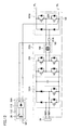
- FIG. 2 shows in detail a configuration of charger 32 shown in Fig. 1 .
- charger 32 includes a rectification unit 102, an inverter 104, an insulating transformer 106, a rectification unit 108, and relays RY1 and RY2.
- Rectification unit 102 includes two upper-and-lower arms connected in parallel, and each upper-and-lower arm includes two rectification elements (diodes) connected in series.
- Power reception terminal 34 is connected to an intermediate point (node N1, N2) of each upper-and-lower arm, and rectification unit 102 rectifies AC electric power inputted from power reception terminal 34.
- the lower arm of each upper-and-lower arm includes a switching element, and further, an electric power line between power reception terminal 34 and node N1, N2 includes a reactor.
- rectification unit 102 constitutes a step-up chopper circuit together with the reactor, and can rectify and step up the electric power inputted from power reception terminal 34.
- Inverter 104 is connected to rectification unit 102 and converts an output from rectification unit 102 to AC.
- Inverter 104 is formed of, for example, a full bridge circuit.
- Insulating transformer 106 is connected between inverter 104 and rectification unit 108, and electrically insulates AC power supply 50 to which power reception terminal 34 is connected from an electrical system of vehicle 1 to which rectification unit 108 is connected.
- Rectification unit 108 includes two upper-and-lower arms connected in parallel between positive electrode line PL and negative electrode line NL, and each upper-and-lower arm includes two rectification elements (diodes) connected in series.
- a secondary coil of insulating transformer 106 is connected to an intermediate node of each upper-and-lower arm, and rectification unit 108 rectifies an output of insulating transformer 106 and outputs the rectified output to positive electrode line PL and negative electrode line NL.
- Rectification unit 102 is formed of the rectification element having more excellent high-frequency rectification property than that of the rectification element constituting rectification unit 108.
- Silicon carbide (SiC), gallium nitride (GaN) and the like are known to have more excellent high-frequency rectification property than general silicon (Si).
- the rectification element of rectification unit 102 is made of SiC and the rectification element of rectification unit 108 is made of general Si.
- non-contact power reception unit 36 is connected to rectification unit 102.
- power reception coil 38 of non-contact power reception unit 36 is connected to nodes N1 and N2 in rectification unit 102.
- the electric power received by non-contact power reception unit 36 is rectified by rectification unit 102.
- non-contact power reception unit 36 is connected to rectification unit 102. This is because the AC electric power received by non-contact power reception unit 36 has a high frequency (particularly in the resonance method, the received AC electric power may have a frequency of 1 M to ten and several megahertz), and thus, rectification unit 102 formed of the rectification element having excellent high-frequency rectification property is used as a rectifier at the time of inductive charging.
- Relay RY1 is provided between node N1 in rectification unit 102 and non-contact power reception unit 36.
- Relay RY2 is provided between node N1 in rectification unit 102 and power reception terminal 34. Relays RY1 and RY2 are turned on/off in accordance with the control signal from charging ECU 40 ( Fig. 1 ).
- rectification unit 102 rectifies electric power (AC) inputted from power reception terminal 34, and outputs the rectified electric power to inverter 104.
- Inverter 104 converts the electric power (DC) outputted from rectification unit 102 to AC.
- Insulating transformer 106 transmits the output (AC) of inverter 104 to rectification unit 108.
- Rectification unit 108 rectifies the electric power (AC) received from insulating transformer 106, and outputs the rectified electric power to positive electrode line PL and negative electrode line NL.
- relay RY1 is turned on and relay RY2 is turned off.
- rectification unit 102 rectifies electric power (AC) received by non-contact power reception unit 36, and outputs the rectified electric power to inverter 104.
- AC electric power
- non-contact power reception unit 36 is connected to rectification unit 102 in charger 32 performing conductive charging.
- rectification unit 102, inverter 104, insulating transformer 106, and rectification unit 108 in charger 32 are used.
- rectification unit 102, inverter 104, insulating transformer 106, and rectification unit 108 in charger 32 are used both at the time of conductive charging and at the time of inductive charging.
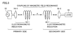
- Fig. 3 is a diagram for describing the resonance method, which is an example of a manner of power reception by non-contact power reception unit 36.
- two LC resonant coils having the same natural frequency resonate each other in the electromagnetic field (near field) similarly to resonance of two tuning forks, to transmit electric power from one coil to the other coil through the electromagnetic field.
- a primary coil 54-2 is connected to AC power supply 52 and high-frequency electric power of 1 M to ten and several megahertz is fed to a primary self-resonant coil 54-1 magnetically coupled to primary coil 54-2 by electromagnetic induction.
- Primary self-resonant coil 54-1 is an LC resonator having inductance and stray capacitance of the coil itself, and resonates with a secondary self-resonant coil 38-1 having the same resonance frequency as that of primary self-resonant coil 54-1, with the electromagnetic field (near field) interposed therebetween.
- energy moves from primary self-resonant coil 54-1 to secondary self-resonant coil 38-1 through the electromagnetic field.
- the energy (electric power) that has moved to secondary self-resonant coil 38-1 is taken out by a secondary coil 38-2 magnetically coupled to secondary self-resonant coil 38-1 by electromagnetic induction, and is supplied to a load 56. It is to be noted that power transmission using the resonance method is implemented when a Q value indicating the resonance strength of primary self-resonant coil 54-1 and secondary self-resonant coil 38-1 is larger than 100, for example.
- secondary self-resonant coil 38-1 and secondary coil 38-2 constitute power reception coil 38 in Fig. 2
- primary self-resonant coil 54-1 and primary coil 54-2 constitute power transmission coil 54 in Fig. 1 .
- electromagnetic induction may be used to transmit electric power from power transmission coil 54 of AC power supply 52 to power reception coil 38 of non-contact power reception unit 36.
- conductive charging during which power reception terminal 34 receives the AC electric power supplied from AC power supply 50 external to the vehicle, and inductive charging during which non-contact power reception unit 36 receives the AC electric power are possible. Since non-contact power reception unit 36 is connected to rectification unit 102 in charger 32, rectification unit 102, inverter 104, insulating transformer 106, and rectification unit 108 in charger 32 are used both at the time of conductive charging and at the time of inductive charging. As a result, separately providing a charger for inductive charging is not necessary. Therefore, according to the first embodiment, both conductive charging (plug-in charging) and inductive charging (non-contact charging) become possible while suppressing an increase in cost.
- non-contact power reception unit 36 is connected to rectification unit 102 formed of the rectification element having more excellent high-frequency rectification property, of rectification units 102 and 108 in charger 32. Therefore, ripples at the time of inductive charging can be sufficiently suppressed.
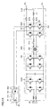
- FIG. 4 shows a configuration of a charger 32A in a second embodiment.
- charger 32A includes rectification units 102A and 108A instead of rectification units 102 and 108, and includes a relay RY3 instead of relay RY2 in the configuration of charger 32 in the first embodiment as shown in Fig. 2 .
- Rectification unit 108A is formed of a rectification element having more excellent high-frequency rectification property than that of a rectification element constituting rectification unit 102A.
- the rectification element of rectification unit 108A is made of SiC, GaN or the like, and the rectification element of rectification unit 102A is made of general Si. It is to be noted that circuit configurations of rectification units 102A and 108A are the same as those of rectification units 102 and 108, respectively.
- non-contact power reception unit 36 is connected to rectification unit 108A.
- power reception coil 38 of non-contact power reception unit 36 is connected to nodes N3 and N4 in rectification unit 108A.
- the electric power received by non-contact power reception unit 36 is rectified by rectification unit 108A.
- non-contact power reception unit 36 is connected to rectification unit 108A, not to rectification unit 102A. This is because the AC electric power received by non-contact power reception unit 36 has a high frequency as described above, and thus, rectification unit 108A formed of the rectification element having excellent high-frequency rectification property is used as a rectifier at the time of inductive charging.
- relay RY1 is provided between node N3 in rectification unit 108A and non-contact power reception unit 36.
- Relay RY3 is provided between node N3 in rectification unit 108A and the secondary coil of insulating transformer 106. Relays RY1 and RY3 are turned on/off in accordance with the control signal from charging ECU 40 ( Fig. 1 ).
- relay RY1 is turned on and relay RY3 is turned off at the time of inductive charging by AC power supply 52. Then, rectification unit 108A rectifies electric power (AC) received by non-contact power reception unit 36, and outputs the rectified electric power to positive electrode line PL and negative electrode line NL. It is to be noted that relay RY1 is turned off and relay RY3 is turned on at the time of conductive charging by AC power supply 50.
- non-contact power reception unit 36 is connected to rectification unit 108A in charger 32A, and rectification unit 108A in charger 32A is used both at the time of conductive charging and at the time of inductive charging. Therefore, according to the second embodiment as well, both conductive charging (plug-in charging) and inductive charging (non-contact charging) become possible while suppressing an increase in cost.
- non-contact power reception unit 36 is connected to rectification unit 108A formed of the rectification element having more excellent high-frequency rectification property, of rectification units 102A and 108A in charger 32A. Therefore, ripples at the time of inductive charging can be sufficiently suppressed.
- FIG. 5 shows a configuration of a charger 32B in a third embodiment.
- charger 32B further includes a transformer 109 in the configuration of charger 32A in the second embodiment as shown in Fig. 4 .
- Transformer 109 is provided between non-contact power reception unit 36 and rectification unit 108A.
- Transformer 109 may be a variable winding type transformer or a fixed winding type transformer.
- Transformer 109 converts AC electric power received by non-contact power reception unit 36 to a predetermined voltage. This predetermined voltage is determined in accordance with a target of a voltage outputted to positive electrode line PL and negative electrode line NL.
- charger 32B is the same as that of charger 32A in the second embodiment as shown in Fig. 4 .
- the voltage conversion function at the time of inductive charging can be implemented with high efficiency and at low cost.
- a rectification unit is provided in a non-contact power reception unit.
- Fig. 6 shows a configuration of a non-contact power reception unit 36A and a charger 32C in the fourth embodiment.
- non-contact power reception unit 36A includes power reception coil 38, a rectification unit 110 and an electromagnetic shielding material 112.
- Rectification unit 110 is connected to power reception coil 38, and rectifies AC electric power received by power reception coil 38 and outputs the electric power to charger 32C.
- rectification unit 110 similarly to the above-mentioned rectification unit in the charger, rectification unit 110 includes two upper-and-lower arms connected in parallel, and each upper-and-lower arm includes two rectification elements (diodes) connected in series.
- Power reception coil 38 is connected to an intermediate point of each upper-and-lower arm.
- rectification unit 110 is preferably formed of a rectification element having excellent high-frequency rectification property such as SiC and GaN, similarly to above-mentioned rectification units 102 and 108A.
- Electromagnetic shielding material 112 shields high-frequency electromagnetic waves (in the case of the resonance method, the frequency may be 1 M to ten and several megahertz) generated around power reception coil 38 and rectification unit 110 with power reception by power reception coil 38.
- the high-frequency electromagnetic waves also propagate to rectification unit 110 rectifying the AC electric power received by power reception coil 38
- electromagnetic shielding material 112 shields power reception coil 38 and rectification unit 110 integrally.
- diffusion of the high-frequency electromagnetic waves generated with inductive charging into the surroundings can be prevented.
- a metallic component such as iron having a high electromagnetic shielding effect, a cloth having an electromagnetic shielding effect or the like can be used as electromagnetic shielding material 112.
- Charger 32C includes rectification unit 102A, inverter 104, insulating transformer 106, and rectification unit 108. Each of rectification unit 102A, inverter 104, insulating transformer 106, and rectification unit 108 has already been described, and thus, a description thereof will not be repeated.
- Non-contact power reception unit 36A is connected to nodes N5 and N6 in a DC link between rectification unit 102A and inverter 104.
- rectification unit 110 is provided in non-contact power reception unit 36A, and thus, electric power does not flow from charger 32C to power reception coil 38 of non-contact power reception unit 36A at the time of conductive charging. Therefore, in the fourth embodiment, relays RY 1 to RY3 as seen in the first to third embodiments are unnecessary.
- the electric power received by power reception coil 38 is rectified by rectification unit 110 and is outputted to charger 32C. Then, the electric power outputted from non-contact power reception unit 36A to charger 32C is subjected to voltage conversion to a predetermined voltage and is outputted to positive electrode line PL and negative electrode line NL by inverter 104, insulating transformer 106 and rectification unit 108 in charger 32C.
- rectification unit 110 is provided in non-contact power reception unit 36A, and thus, the electric power inputted from power reception terminal 34 does not flow to power reception coil 38 of non-contact power reception unit 36A.
- the electric power received by power reception coil 38 of non-contact power reception unit 36A does not flow to power reception terminal 34, either. Therefore, in the fourth embodiment, conductive charging during which power reception terminal 34 receives the charging power and inductive charging during which power reception coil 38 receives the charging power can also be performed at the same time.
- both conductive charging and inductive charging become possible.
- power reception coil 38 and rectification unit 110 can be integrally shielded from electromagnetic waves, and thus, a configuration of the shield is also simplified.
- conductive charging and inductive charging can be performed at the same time, and thus, the charging time can be shortened.
- a description will be given to a configuration including the voltage conversion function when a non-contact power reception unit is formed of above-mentioned non-contact power reception unit 36A.
- Fig. 7 shows a configuration of a charger 32D in the fifth embodiment.
- charger 32D includes a rectification unit 108B instead of rectification unit 108, and further includes a reactor L1 and relays RY3 to RY5 in the configuration of charger 32C in the fourth embodiment as shown in Fig. 6 .
- Rectification unit 108B includes a switching element provided at each arm of one upper and lower arms in the configuration of rectification unit 108 (the upper-and-lower arm including the switching element will also be referred to as "upper-and-lower arm ARM" hereinafter).
- Relay RY3 is disposed between an intermediate node N3 of upper-and-lower arm ARM and the secondary coil of insulating transformer 106.
- Relay RY4 is disposed between a node N7 on the positive electrode side of upper-and-lower arm ARM and a node N10 on positive electrode line PL.
- Relay RY5 and reactor L1 are connected in series between node N3 and node N10.
- Non-contact power reception unit 36A is connected to nodes N7 and N8.
- relays RY3 and RY4 are turned on and relay RY5 is turned off in accordance with a signal from charging ECU 40 ( Fig. 1 ).
- the AC electric power inputted from power reception terminal 34 is subjected to voltage conversion and is outputted to positive electrode line PL and negative electrode line NL by rectification unit 102A, inverter 104, insulating transformer 106, and rectification unit 108B.
- relays RY3 and RY4 are turned off and relay RY5 is turned on in accordance with the signal from charging ECU 40.
- insulating transformer 106 is electrically disconnected from rectification unit 108B, and reactor L1 is electrically connected between the intermediate node of upper-and-lower arm ARM and positive electrode line PL.
- upper-and-lower arm ARM and reactor L1 form a step-down-type chopper circuit, and DC electric power outputted from non-contact power reception unit 36A is converted to a predetermined voltage and is outputted to positive electrode line PL and negative electrode line NL.
- the voltage conversion function (step-down type) at the time of inductive charging can be implemented with high efficiency and at low cost, in addition to the effect similar to that in the fourth embodiment.
- the step-down-type chopper circuit is formed using rectification unit 108B in the fifth embodiment, whereas a step-up-type chopper circuit is formed using rectification unit 108B in a sixth embodiment.
- Fig. 9 shows a configuration of a charger 32E in the sixth embodiment.
- charger 32E includes rectification unit 108B instead of rectification unit 108, and further includes a reactor L2 and relay RY3 in the configuration of charger 32C in the fourth embodiment as shown in Fig. 6 .
- Non-contact power reception unit 36A is connected between intermediate node N3 of upper-and-lower arm ARM and a node N8 on the negative electrode side of upper-and-lower arm ARM.
- Reactor L2 is disposed on an electric power line between node N3 and non-contact power reception unit 36A. It is to be noted that the remaining configuration has already been described, and thus, a description thereof will not be repeated.
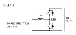
- relay RY3 is turned off. Then, insulating transformer 106 is electrically disconnected from rectification unit 108B. As a result, as shown in Fig. 10 , upper-and-lower arm ARM and reactor L2 form the step-up-type chopper circuit, and DC electric power outputted from non-contact power reception unit 36A is converted to a predetermined voltage and is outputted to positive electrode line PL and negative electrode line NL.
- the voltage conversion function (step-up type) at the time of inductive charging can be implemented with high efficiency and at low cost, in addition to the effect similar to that in the fourth embodiment.
- the step-down-type chopper circuit is formed at the time of inductive charging by separately providing reactor L1 in the fifth embodiment, whereas the secondary coil of insulating transformer 106 is also used as a reactor of a chopper circuit without separately providing reactor L1 in a seventh embodiment.
- Fig. 11 shows a configuration of a charger 32F in the seventh embodiment.
- charger 32F does not include reactor L1 and includes relays RY6 and RY7 instead of relays RY3 and RY5 in the configuration of charger 32D in the fifth embodiment as shown in Fig. 7 .
- Relay RY6 is disposed between an intermediate node N4 of the upper-and-lower arm different from upper-and-lower arm ARM in rectification unit 108B and the secondary coil of insulating transformer 106.
- Relay RY7 is disposed between a node N9, which is a connection point between the secondary coil of insulating transformer 106 and relay RY6, and node N10 on positive electrode line PL. It is to be noted that the remaining configuration of charger 32F is the same as that of charger 32D.
- relays RY4 and RY6 are turned on and relay RY7 is turned off in accordance with the signal from charging ECU 40 ( Fig. 1 ).
- AC electric power inputted from power reception terminal 34 is subjected to voltage conversion and is outputted to positive electrode line PL and negative electrode line NL by rectification unit 102A, inverter 104, insulating transformer 106, and rectification unit 108B.
- relays RY4 and RY6 are turned off and relay RY7 is turned on in accordance with the signal from charging ECU 40.
- upper-and-lower arm ARM and the secondary coil of insulating transformer 106 form the step-down-type chopper circuit, and DC electric power outputted from non-contact power reception unit 36A is converted to a predetermined voltage and is outputted to positive electrode line PL and negative electrode line NL.
- the voltage conversion function (step-down type) at the time of inductive charging can be implemented with high efficiency and at low cost without separately providing the reactor.
- the step-up-type chopper circuit is formed at the time of inductive charging by separately providing reactor L2 in the sixth embodiment, whereas the secondary coil of insulating transformer 106 is also used as a reactor of a chopper circuit without separately providing reactor L2 in an eighth embodiment.
- Fig. 12 shows a configuration of a charger 32G in the eighth embodiment.
- charger 32G does not include reactor L2 and includes relay RY6 instead of relay RY3 in the configuration of charger 32E in the sixth embodiment as shown in Fig. 9 .
- Non-contact power reception unit 36A is connected to nodes N8 and N9. It is to be noted that the remaining configuration of charger 32G is the same as that of charger 32E.
- relay RY6 is turned on in accordance with the signal from charging ECU 40 ( Fig. 1 ).
- AC electric power inputted from power reception terminal 34 is subjected to voltage conversion and is outputted to positive electrode line PL and negative electrode line NL by rectification unit 102A, inverter 104, insulating transformer 106, and rectification unit 108B.
- relay RY6 is turned off in accordance with the signal from charging ECU 40.
- the secondary coil of insulating transformer 106 and upper-and-lower arm ARM form the step-up-type chopper circuit, and DC electric power outputted from non-contact power reception unit 36A is converted to a predetermined voltage and is outputted to positive electrode line PL and negative electrode line NL.
- the voltage conversion function (step-up type) at the time of inductive charging can be implemented with high efficiency and at low cost without separately providing the reactor.
- FIG. 13 shows a configuration of a charger 32H in a ninth embodiment.
- charger 32H includes inverters 102B and 108C instead of rectification units 102A and 108B, respectively, in the configuration of charger 32D in the fifth embodiment as shown in Fig. 7 .
- Inverters 102B and 108C are each formed of a full bridge circuit similarly to inverter 104.
- Inverter 102B can convert AC electric power inputted from power reception terminal 34 to DC and output the DC electric power to inverter 104 in accordance with the signal from charging ECU 40 ( Fig. 1 ).
- inverter 102B can convert DC electric power received from inverter 104 to AC and output the AC electric power to power reception terminal 34.
- Inverter 108C can also convert AC electric power received from insulating transformer 106 to DC and output the DC electric power to positive electrode line PL and negative electrode line NL in accordance with the signal from charging ECU 40. In addition, inverter 108C can convert DC electric power received from positive electrode line PL and negative electrode line NL to AC and output the AC electric power to insulating transformer 106.
- this charger 32H allows bidirectional electric power conversion between power reception terminal 34 and positive and negative electrode lines PL and NL.
- Conductive charging during which the charging power is inputted from power reception terminal 34 and inductive charging (step-down type) using non-contact power reception unit 36A are possible, and electric power feeding from power reception terminal 34 to an electrical load external to the vehicle is also possible.
- the voltage conversion function (step-down type) at the time of inductive charging can be implemented with high efficiency and at low cost, in addition to the effect similar to that in the fourth embodiment. Furthermore, electric power feeding from power reception terminal 34 to the electrical load external to the vehicle is also possible.
- FIG. 14 shows a configuration of a charger 32I in a tenth embodiment.
- charger 32I includes inverters 102B and 108C instead of rectification units 102A and 108B, respectively, in the configuration of charger 32E in the sixth embodiment as shown in Fig. 9 .
- Inverters 102B and 108C are as described above.
- This charger 32I also allows bidirectional electric power conversion between power reception terminal 34 and positive and negative electrode lines PL and NL. Conductive charging during which the charging power is inputted from power reception terminal 34 and inductive charging (step-up type) using non-contact power reception unit 36A are possible, and electric power feeding from power reception terminal 34 to the electrical load external to the vehicle is also possible.
- the voltage conversion function (step-up type) at the time of inductive charging can be implemented with high efficiency and at low cost, in addition to the effect similar to that in the fourth embodiment. Furthermore, electric power feeding from power reception terminal 34 to the electrical load external to the vehicle is also possible.
- vehicle 1 includes converter 24, and charger 32 (32A to 32I) and DC/DC converter 42 are connected between converter 24 and system main relay (SMR) 28 in each of the above-mentioned embodiments, the present invention is also applicable to a vehicle 1 A that does not include converter 24 as shown in Fig. 15 .
- the resonance method has been described in Fig. 3 as an example of a manner of power reception by non-contact power reception unit 36 or 36A in the above.
- the manner of power reception by non-contact power reception unit 36 or 36A is not, however, limited to the resonance method, but may be electromagnetic induction, for example.
- non-contact power reception unit 36 (or 36A) is connected to the rectification unit having more excellent high-frequency rectification property, of the two rectification units included in the charger in each embodiment other than the fourth embodiment.
- the present invention is also applicable, however, to a charger including two rectification units having the same level of high-frequency rectification property.
- the ninth and tenth embodiments in which electric power feeding from power reception terminal 34 to the electrical load external to the vehicle is possible correspond to the fifth and sixth embodiments, respectively.
- electric power feeding from power reception terminal 34 to the electrical load external to the vehicle becomes possible by replacing the rectification unit in the charger with the inverter.
- the charger is connected to positive electrode line PL and negative electrode line NL in each of the above-mentioned embodiments, the charger may be connected to main positive bus MPL and main negative bus MNL.
- the present invention is also applicable to hybrid vehicles of other types.
- the present invention is also applicable to vehicles such as a so-called series-type hybrid vehicle using only engine 10 for driving motor generator 12 and using only motor generator 14 for generating driving force for the vehicle, a hybrid vehicle recovering, as electrical energy, only the regenerative energy from the kinetic energy generated by engine 10, and a motor-assisted-type hybrid vehicle using an engine as a main motive power source and assisted by a motor as required.
- the present invention is also applicable to an electric vehicle that does not include engine 10 and runs using electric power only, or a fuel cell vehicle further including a fuel cell as a DC power supply in addition to power storage device 26.
- rectification units 102, 102A and 102B correspond to “first rectification unit” in the present invention
- rectification units 108, 108A to 108C correspond to “second rectification unit” in the present invention
- transformer 109 corresponds to "voltage conversion device” in the present invention
- rectification unit 110 corresponds to "third rectification unit” in the present invention.
Landscapes
- Engineering & Computer Science (AREA)
- Power Engineering (AREA)
- Transportation (AREA)
- Mechanical Engineering (AREA)
- Computer Networks & Wireless Communication (AREA)
- Life Sciences & Earth Sciences (AREA)
- Sustainable Development (AREA)
- Sustainable Energy (AREA)
- Charge And Discharge Circuits For Batteries Or The Like (AREA)
- Electric Propulsion And Braking For Vehicles (AREA)
- Secondary Cells (AREA)
Abstract
Description
- The present invention relates to a vehicle charging apparatus, and particularly to a vehicle charging apparatus for charging a power storage device mounted on a vehicle by an AC power supply external to the vehicle.
- Japanese Patent Laying-Open No.
2008-220130 - According to this power supply system for a vehicle, a selection can be made between conductive charging with the conductive charging means and inductive charging with the inductive charging means to charge the power storage unit, and thus, an area where the power storage unit can be charged can be expanded (see PTL 1).
-
- PTL 1: Japanese Patent Laying-Open No.
2008-220130 - PTL 2: Japanese Patent Laying-Open No.
2003-47163 - The power supply system for a vehicle disclosed in above-mentioned Japanese Patent Laying-Open No.
2008-220130 - Thus, an object of the present invention is to provide a vehicle charging apparatus that allows both conductive charging (plug-in charging) and inductive charging (non-contact charging) and can suppress an increase in cost.
- According to the present invention, a vehicle charging apparatus is a vehicle charging apparatus for charging a power storage device mounted on a vehicle by an AC power supply external to the vehicle, including: a power reception terminal, a charger and a non-contact power reception unit. The power reception terminal is configured to be electrically connectable to the AC power supply. The charger is configured to convert AC electric power inputted from the power reception terminal to a predetermined DC voltage. The non-contact power reception unit is configured to be magnetically coupled to a power transmission unit of the AC power supply to receive electric power from the AC power supply in a non-contact manner. The non-contact power reception unit is connected to a power conversion circuit of the charger.
- Preferably, the charger includes first and second rectification units, an inverter and an insulating transformer. The first rectification unit is configured to be capable of rectifying the AC electric power inputted from the power reception terminal. The inverter is connected to the first rectification unit. The insulating transformer is connected to the inverter. The second rectification unit is configured to rectify an output of the insulating transformer. The non-contact power reception unit is connected to either the first rectification unit or the second rectification unit.
- More preferably, one rectification unit of the first and second rectification units is formed of a rectification element having more excellent high-frequency rectification property than that of a rectification element constituting the other rectification unit. The non-contact power reception unit is connected to the one rectification unit.
- In addition, preferably, the non-contact power reception unit is connected to the second rectification unit. The vehicle charging apparatus further includes a voltage conversion device. The voltage conversion device is provided between the non-contact power reception unit and the second rectification unit.
- Preferably, the charger includes first and second rectification units, an inverter and an insulating transformer. The first rectification unit is configured to be capable of rectifying the AC electric power inputted from the power reception terminal. The inverter is connected to the first rectification unit. The insulating transformer is connected to the inverter. The second rectification unit is configured to rectify an output of the insulating transformer. The non-contact power reception unit includes a power reception coil and a third rectification unit. The power reception coil is configured to be magnetically coupled to a power transmission coil provided at the power transmission unit. The third rectification unit is configured to rectify an output of the power reception coil. The third rectification unit is connected between the first rectification unit and the inverter.
- In addition, preferably, the charger includes first and second rectification units, an inverter and an insulating transformer. The first rectification unit is configured to be capable of rectifying the AC electric power inputted from the power reception terminal. The inverter is connected to the first rectification unit. The insulating transformer is connected to the inverter. The second rectification unit is configured to rectify an output of the insulating transformer. The non-contact power reception unit includes a power reception coil and a third rectification unit. The power reception coil is configured to be magnetically coupled to a power transmission coil provided at the power transmission unit. The third rectification unit is configured to rectify an output of the power reception coil. The second rectification unit includes first and second upper-and-lower arms. The first and second upper-and-lower arms are connected in parallel between a positive electrode output line and a negative electrode output line of the charger. Each arm of the first upper-and-lower arm includes a switching element. A secondary coil of the insulating transformer is connected between an intermediate point of the first upper-and-lower arm and an intermediate point of the second upper-and-lower arm. The charger further includes a reactor. The reactor is connected between the intermediate point of the first upper-and-lower arm and the positive electrode output line. The third rectification unit is connected to the positive electrode output line and the negative electrode output line of the charger.
- In addition, preferably, the charger includes first and second rectification units, an inverter and an insulating transformer. The first rectification unit is configured to be capable of rectifying the AC electric power inputted from the power reception terminal. The inverter is connected to the first rectification unit. The insulating transformer is connected to the inverter. The second rectification unit is configured to rectify an output of the insulating transformer. The non-contact power reception unit includes a power reception coil and a third rectification unit. The power reception coil is configured to be magnetically coupled to a power transmission coil provided at the power transmission unit. The third rectification unit is configured to rectify an output of the power reception coil. The second rectification unit includes first and second upper-and-lower arms. The first and second upper-and-lower arms are connected in parallel between a positive electrode output line and a negative electrode output line of the charger. Each arm of the first upper-and-lower arm includes a switching element. A secondary coil of the insulating transformer is connected between an intermediate point of the first upper-and-lower arm and an intermediate point of the second upper-and-lower arm. The charger further includes a reactor. The reactor is connected between one output end of the third rectification unit and the intermediate point of the first upper-and-lower arm. The other output end of the third rectification unit is connected to the negative electrode output line of the charger.
- In addition, preferably, the charger includes first and second rectification units, an inverter and an insulating transformer. The first rectification unit is configured to be capable of rectifying the AC electric power inputted from the power reception terminal. The inverter is connected to the first rectification unit. The insulating transformer is connected to the inverter. The second rectification unit is configured to rectify an output of the insulating transformer. The non-contact power reception unit includes a power reception coil and a third rectification unit. The power reception coil is configured to be magnetically coupled to a power transmission coil provided at the power transmission unit. The third rectification unit is configured to rectify an output of the power reception coil. The second rectification unit includes first and second upper-and-lower arms. The first and second upper-and-lower arms are connected in parallel between a positive electrode output line and a negative electrode output line of the charger. Each arm of the first upper-and-lower arm includes a switching element. A secondary coil of the insulating transformer is connected between an intermediate point of the first upper-and-lower arm and an intermediate point of the second upper-and-lower arm. The third rectification unit is connected to the positive electrode output line and the negative electrode output line of the charger. The charger further includes a switching device. The switching device breaks electrical connection between the secondary coil of the insulating transformer and the intermediate point of the second upper-and-lower arm, and electrically connects the secondary coil to the positive electrode output line, when the non-contact power reception unit is used for charging.
- In addition, preferably, the charger includes first and second rectification units, an inverter and an insulating transformer. The first rectification unit is configured to be capable of rectifying the AC electric power inputted from the power reception terminal. The inverter is connected to the first rectification unit. The insulating transformer is connected to the inverter. The second rectification unit is configured to rectify an output of the insulating transformer. The non-contact power reception unit includes a power reception coil and a third rectification unit. The power reception coil is configured to be magnetically coupled to a power transmission coil provided at the power transmission unit. The third rectification unit is configured to rectify an output of the power reception coil. The second rectification unit includes first and second upper-and-lower arms. The first and second upper-and-lower arms are connected in parallel between a positive electrode output line and a negative electrode output line of the charger. Each arm of the first upper-and-lower arm includes a switching element. A secondary coil of the insulating transformer is connected between an intermediate point of the first upper-and-lower arm and an intermediate point of the second upper-and-lower arm. The charger further includes a switching device. The switching device breaks electrical connection between the secondary coil of the insulating transformer and the intermediate point of the second upper-and-lower arm, and electrically connects the secondary coil to one output end of the third rectification unit, when the non-contact power reception unit is used for charging. The other output end of the third rectification unit is connected to the negative electrode output line of the charger.
- Preferably, the non-contact power reception unit further includes an electromagnetic shielding material. The electromagnetic shielding material integrally shields the power reception coil and the third rectification unit from electromagnetic waves.
- In this vehicle charging apparatus, conductive charging during which the power reception terminal receives the AC electric power supplied from the AC power supply external to the vehicle and inductive charging during which the non-contact power reception unit receives the AC electric power are possible. Since the non-contact power reception unit is connected to the power conversion circuit of the charger, at least a part of power elements constituting the power conversion circuit are used both at the time of conductive charging and at the time of inductive charging. As a result, the number of components can be reduced as compared with the case where a charger for conductive charging and a charger for inductive charging are provided separately.
- Therefore, according to this vehicle charging apparatus, both conductive charging (plug-in charging) and inductive charging (non-contact charging) are possible while suppressing an increase in cost.
-
-
Fig. 1 is an overall configuration diagram of a vehicle to which a vehicle charging apparatus according to a first embodiment of the present invention is applied. -
Fig. 2 shows in detail a configuration of a charger shown inFig. 1 . -
Fig. 3 is a diagram for describing a resonance method, which is an example of a manner of power reception by a non-contact power reception unit. -
Fig. 4 shows a configuration of a charger in a second embodiment. -
Fig. 5 shows a configuration of a charger in a third embodiment. -
Fig. 6 shows a configuration of a non-contact power reception unit and a charger in a fourth embodiment. -
Fig. 7 shows a configuration of a charger in a fifth embodiment. -
Fig. 8 shows a step-down-type chopper circuit formed by upper and lower arms and a reactor. -
Fig. 9 shows a configuration of a charger in a sixth embodiment. -
Fig. 10 shows a step-up-type chopper circuit formed by upper and lower arms and a reactor. -
Fig. 11 shows a configuration of a charger in a seventh embodiment. -
Fig. 12 shows a configuration of a charger in an eighth embodiment. -
Fig. 13 shows a configuration of a charger in a ninth embodiment. -
Fig. 14 shows a configuration of a charger in a tenth embodiment. -
Fig. 15 is an overall configuration diagram of a vehicle that does not include a converter. - Embodiments of the present invention will be described in detail hereinafter with reference to the drawings, in which the same or corresponding portions are denoted with the same reference characters and a description thereof will not be repeated.
-
Fig. 1 is an overall configuration diagram of a vehicle to which a vehicle charging apparatus according to a first embodiment of the present invention is applied. Referring toFig. 1 , avehicle 1 includes anengine 10,motor generators power split device 16, and adriving wheel 18.Vehicle 1 further includesinverters converter 24, apower storage device 26, a system main relay (SMR) 28, and an MG-ECU (Electronic Control Unit) 30.Vehicle 1 further includes acharger 32, apower reception terminal 34, a non-contactpower reception unit 36, and a chargingECU 40.Vehicle 1 further includes a DC/DC converter 42 and anauxiliary machine 44. -
Engine 10 is configured to be capable of converting thermal energy generated by combustion of fuel to kinetic energy of kinetic elements such as a piston and a rotor, and outputting the kinetic energy topower split device 16. Power splitdevice 16 is configured to be capable of splitting the kinetic energy generated byengine 10 intomotor generator 12 anddriving wheel 18. For example, a planetary gear having three rotation shafts of a sun gear, a planetary carrier and a ring gear can be used as power splitdevice 16, and these three rotation shafts are linked to a rotation shaft ofmotor generator 12, a crankshaft ofengine 10 and a drive shaft (driving wheel 18) of the vehicle, respectively. -
Motor generators Motor generator 12 has the rotation shaft linked topower split device 16 and is driven byinverter 20.Motor generator 12 receives the kinetic energy generated byengine 10 frompower split device 16, converts the kinetic energy to electrical energy, and outputs the electrical energy toinverter 20. In addition,motor generator 12 generates driving force using three-phase AC electric power received frominverter 20, to start upengine 10. -
Motor generator 14 has a rotation shaft linked to the drive shaft (driving wheel 18) of the vehicle.Motor generator 14 is driven byinverter 22 and generates driving torque of the vehicle using three-phase AC electric power received frominverter 22. In addition, at the time of braking the vehicle or at the time of reducing acceleration on a descending slope,motor generator 14 receives, from drivingwheel 18, mechanical energy stored in the vehicle as kinetic energy or potential energy, converts the mechanical energy to electrical energy (regenerative electric power generation), and outputs the electrical energy toinverter 22. -
Engine 10 is incorporated intovehicle 1 as a power source drivingmotor generator 12 anddriving wheel 18.Motor generator 12 is incorporated intovehicle 1 operating as a generator driven byengine 10 and operating as a motor that can start upengine 10.Motor generator 14 is incorporated intovehicle 1 operating as a motor drivingdriving wheel 18 and operating as a generator capable of regenerative electric power generation using the mechanical energy stored in the vehicle. -
Inverter 20 drivesmotor generator 12 based on a signal PWI1 from MG-ECU 30, andinverter 22drives motor generator 14 based on a signal PWI2 from MG-ECU 30.Inverters inverters -
Inverter 20 drivesmotor generator 12 in a regenerative mode based on signal PWI1, converts electric power generated bymotor generator 12 to DC electric power, and outputs the DC electric power to main positive bus MPL and main negative bus MNL. In addition, at the time of starting upengine 10,inverter 20drives motor generator 12 in a power running mode based on signal PWI1, converts DC electric power supplied from main positive bus MPL and main negative bus MNL to AC electric power, and outputs the AC electric power tomotor generator 12. -
Inverter 22 drivesmotor generator 14 in the power running mode based on signal PWI2, converts DC electric power supplied from main positive bus MPL and main negative bus MNL to AC electric power, and outputs the AC electric power tomotor generator 14. In addition, at the time of braking the vehicle or at the time of reducing acceleration on a descending slope,inverter 22drives motor generator 14 in the regenerative mode based on signal PWI2, converts electric power generated bymotor generator 14 to DC electric power, and outputs the DC electric power to main positive bus MPL and main negative bus MNL. -
Converter 24 is connected between positive and negative electrode lines PL, NL and main positive and negative buses MPL, MNL.Converter 24 steps up a voltage between main positive bus MPL and main negative bus MNL to a voltage between positive electrode line PL and negative electrode line NL or a higher voltage, based on a signal PWC from MG-ECU 30.Converter 24 is formed of, for example, a step-up chopper circuit. -
Power storage device 26 is a rechargeable DC power supply and is formed of, for example, a secondary battery such as a nickel-metal hydride secondary battery or a lithium ion secondary battery.Power storage device 26 is electrically connected to positive electrode line PL and negative electrode line NL by systemmain relay 28, and outputs electric power to positive electrode line PL and negative electrode line NL. In addition,power storage device 26 is charged by receiving electric power generated by at least one ofmotor generators converter 24. Furthermore,power storage device 26 is charged by receiving electric power supplied fromAC power supply charger 32. It is to be noted that a large-capacitance capacitor can also be used aspower storage device 26. - System
main relay 28 is provided betweenpower storage device 26 and positive and negative electrode lines PL, NL, and is turned on at the time of starting up a vehicle system or at the time of chargingpower storage device 26 by AC power supply 50 (or 52). -
Charger 32 is connected to positive electrode line PL and negative electrode line NL.Charger 32 receives AC electric power supplied fromAC power supply 50 frompower reception terminal 34, converts the AC electric power inputted frompower reception terminal 34 to a voltage level ofpower storage device 26 based on a control signal from chargingECU 40, and outputs the converted electric power to positive electrode line PL and negative electrode line NL. - Non-contact power reception unit 36 (described below) is connected to
charger 32. At the time of chargingpower storage device 26 using non-contactpower reception unit 36,charger 32 receives AC electric power received fromAC power supply 52 by non-contactpower reception unit 36 from non-contactpower reception unit 36, converts the AC electric power received from non-contactpower reception unit 36 to a voltage level ofpower storage device 26 based on the control signal from chargingECU 40, and outputs the converted electric power to positive electrode line PL and negative electrode line NL. This configuration ofcharger 32 will be described in detail later. -
Power reception terminal 34 is an electric power interface for conductive charging byAC power supply 50 external to the vehicle.Power reception terminal 34 is configured to be electrically connectable to a power supply outlet and the like (not shown) ofAC power supply 50. - Non-contact
power reception unit 36 is an electric power interface for inductive charging (non-contact charging) byAC power supply 52 external to the vehicle. Non-contactpower reception unit 36 includes apower reception coil 38 that can be magnetically coupled to apower transmission coil 54 ofAC power supply 52.Power reception coil 38 is magnetically coupled topower transmission coil 54 ofAC power supply 52 to receive electric power fromAC power supply 52 in a non-contact manner. It is to be noted that magnetic coupling betweenpower reception coil 38 andpower transmission coil 54 may be implemented by electromagnetic induction or a resonance method of resonatingpower reception coil 38 andpower transmission coil 54 with the magnetic field interposed therebetween. - At the time of charging
power storage device 26 byAC power supply ECU 40 controls the operation ofcharger 32. In the first embodiment, conductive charging byAC power supply 50 and inductive charging byAC power supply 52 cannot be performed at the same time, and thus, chargingECU 40 also performs control over switching between conductive charging and inductive charging. - DC/
DC converter 42 is connected to positive electrode line PL and negative electrode line NL. DC/DC converter 42 steps down electric power received from positive electrode line PL and negative electrode line NL to an operation voltage ofauxiliary machine 44, and outputs the electric power toauxiliary machine 44.Auxiliary machine 44 comprehensively represents each auxiliary machine of thisvehicle 1 and is supplied with electric power from DC/DC converter 42. -
Fig. 2 shows in detail a configuration ofcharger 32 shown inFig. 1 . Referring toFig. 2 ,charger 32 includes arectification unit 102, aninverter 104, an insulatingtransformer 106, arectification unit 108, and relays RY1 and RY2. -
Rectification unit 102 includes two upper-and-lower arms connected in parallel, and each upper-and-lower arm includes two rectification elements (diodes) connected in series.Power reception terminal 34 is connected to an intermediate point (node N1, N2) of each upper-and-lower arm, andrectification unit 102 rectifies AC electric power inputted frompower reception terminal 34. It is to be noted that the lower arm of each upper-and-lower arm includes a switching element, and further, an electric power line betweenpower reception terminal 34 and node N1, N2 includes a reactor. As a result,rectification unit 102 constitutes a step-up chopper circuit together with the reactor, and can rectify and step up the electric power inputted frompower reception terminal 34.Inverter 104 is connected torectification unit 102 and converts an output fromrectification unit 102 to AC.Inverter 104 is formed of, for example, a full bridge circuit. Insulatingtransformer 106 is connected betweeninverter 104 andrectification unit 108, and electrically insulatesAC power supply 50 to whichpower reception terminal 34 is connected from an electrical system ofvehicle 1 to whichrectification unit 108 is connected. -
Rectification unit 108 includes two upper-and-lower arms connected in parallel between positive electrode line PL and negative electrode line NL, and each upper-and-lower arm includes two rectification elements (diodes) connected in series. A secondary coil of insulatingtransformer 106 is connected to an intermediate node of each upper-and-lower arm, andrectification unit 108 rectifies an output of insulatingtransformer 106 and outputs the rectified output to positive electrode line PL and negative electrode line NL. -
Rectification unit 102 is formed of the rectification element having more excellent high-frequency rectification property than that of the rectification element constitutingrectification unit 108. Silicon carbide (SiC), gallium nitride (GaN) and the like are known to have more excellent high-frequency rectification property than general silicon (Si). For example, the rectification element ofrectification unit 102 is made of SiC and the rectification element ofrectification unit 108 is made of general Si. - In the first embodiment, non-contact
power reception unit 36 is connected torectification unit 102. In other words,power reception coil 38 of non-contactpower reception unit 36 is connected to nodes N1 and N2 inrectification unit 102. At the time of inductive charging during which non-contactpower reception unit 36 receives charging power, the electric power received by non-contactpower reception unit 36 is rectified byrectification unit 102. - In the present embodiment, non-contact
power reception unit 36 is connected torectification unit 102. This is because the AC electric power received by non-contactpower reception unit 36 has a high frequency (particularly in the resonance method, the received AC electric power may have a frequency of 1 M to ten and several megahertz), and thus,rectification unit 102 formed of the rectification element having excellent high-frequency rectification property is used as a rectifier at the time of inductive charging. - Relay RY1 is provided between node N1 in
rectification unit 102 and non-contactpower reception unit 36. Relay RY2 is provided between node N1 inrectification unit 102 andpower reception terminal 34. Relays RY1 and RY2 are turned on/off in accordance with the control signal from charging ECU 40 (Fig. 1 ). - In this
charger 32, at the time of conductive charging byAC power supply 50, relay RY1 is turned off and relay RY2 is turned on. Then,rectification unit 102 rectifies electric power (AC) inputted frompower reception terminal 34, and outputs the rectified electric power toinverter 104.Inverter 104 converts the electric power (DC) outputted fromrectification unit 102 to AC. Insulatingtransformer 106 transmits the output (AC) ofinverter 104 torectification unit 108.Rectification unit 108 rectifies the electric power (AC) received from insulatingtransformer 106, and outputs the rectified electric power to positive electrode line PL and negative electrode line NL. - At the time of inductive charging by
AC power supply 52, relay RY1 is turned on and relay RY2 is turned off. Then,rectification unit 102 rectifies electric power (AC) received by non-contactpower reception unit 36, and outputs the rectified electric power toinverter 104. It is to be noted that the subsequent processing byinverter 104, insulatingtransformer 106 andrectification unit 108 is as described above. - As described above, in the first embodiment, non-contact
power reception unit 36 is connected torectification unit 102 incharger 32 performing conductive charging. At the time of inductive charging using non-contactpower reception unit 36,rectification unit 102,inverter 104, insulatingtransformer 106, andrectification unit 108 incharger 32 are used. In other words,rectification unit 102,inverter 104, insulatingtransformer 106, andrectification unit 108 incharger 32 are used both at the time of conductive charging and at the time of inductive charging. -
Fig. 3 is a diagram for describing the resonance method, which is an example of a manner of power reception by non-contactpower reception unit 36. Referring toFig. 3 , in the resonance method, two LC resonant coils having the same natural frequency resonate each other in the electromagnetic field (near field) similarly to resonance of two tuning forks, to transmit electric power from one coil to the other coil through the electromagnetic field. - For example, a primary coil 54-2 is connected to
AC power supply 52 and high-frequency electric power of 1 M to ten and several megahertz is fed to a primary self-resonant coil 54-1 magnetically coupled to primary coil 54-2 by electromagnetic induction. Primary self-resonant coil 54-1 is an LC resonator having inductance and stray capacitance of the coil itself, and resonates with a secondary self-resonant coil 38-1 having the same resonance frequency as that of primary self-resonant coil 54-1, with the electromagnetic field (near field) interposed therebetween. As a result, energy (electric power) moves from primary self-resonant coil 54-1 to secondary self-resonant coil 38-1 through the electromagnetic field. The energy (electric power) that has moved to secondary self-resonant coil 38-1 is taken out by a secondary coil 38-2 magnetically coupled to secondary self-resonant coil 38-1 by electromagnetic induction, and is supplied to aload 56. It is to be noted that power transmission using the resonance method is implemented when a Q value indicating the resonance strength of primary self-resonant coil 54-1 and secondary self-resonant coil 38-1 is larger than 100, for example. - It is to be noted that secondary self-resonant coil 38-1 and secondary coil 38-2 constitute
power reception coil 38 inFig. 2 , and primary self-resonant coil 54-1 and primary coil 54-2 constitutepower transmission coil 54 inFig. 1 . - As described above, electromagnetic induction may be used to transmit electric power from
power transmission coil 54 ofAC power supply 52 topower reception coil 38 of non-contactpower reception unit 36. - As described above, in the first embodiment, conductive charging during which
power reception terminal 34 receives the AC electric power supplied fromAC power supply 50 external to the vehicle, and inductive charging during which non-contactpower reception unit 36 receives the AC electric power are possible. Since non-contactpower reception unit 36 is connected torectification unit 102 incharger 32,rectification unit 102,inverter 104, insulatingtransformer 106, andrectification unit 108 incharger 32 are used both at the time of conductive charging and at the time of inductive charging. As a result, separately providing a charger for inductive charging is not necessary. Therefore, according to the first embodiment, both conductive charging (plug-in charging) and inductive charging (non-contact charging) become possible while suppressing an increase in cost. - In addition, in the first embodiment, non-contact
power reception unit 36 is connected torectification unit 102 formed of the rectification element having more excellent high-frequency rectification property, ofrectification units charger 32. Therefore, ripples at the time of inductive charging can be sufficiently suppressed. -
Fig. 4 shows a configuration of acharger 32A in a second embodiment. Referring toFig. 4 ,charger 32A includesrectification units rectification units charger 32 in the first embodiment as shown inFig. 2 . -
Rectification unit 108A is formed of a rectification element having more excellent high-frequency rectification property than that of a rectification element constitutingrectification unit 102A. For example, the rectification element ofrectification unit 108A is made of SiC, GaN or the like, and the rectification element ofrectification unit 102A is made of general Si. It is to be noted that circuit configurations ofrectification units rectification units - In the second embodiment, non-contact
power reception unit 36 is connected torectification unit 108A. In other words,power reception coil 38 of non-contactpower reception unit 36 is connected to nodes N3 and N4 inrectification unit 108A. At the time of inductive charging during which non-contactpower reception unit 36 receives the charging power, the electric power received by non-contactpower reception unit 36 is rectified byrectification unit 108A. - In the present embodiment, non-contact
power reception unit 36 is connected torectification unit 108A, not to rectificationunit 102A. This is because the AC electric power received by non-contactpower reception unit 36 has a high frequency as described above, and thus,rectification unit 108A formed of the rectification element having excellent high-frequency rectification property is used as a rectifier at the time of inductive charging. - In the second embodiment, relay RY1 is provided between node N3 in
rectification unit 108A and non-contactpower reception unit 36. Relay RY3 is provided between node N3 inrectification unit 108A and the secondary coil of insulatingtransformer 106. Relays RY1 and RY3 are turned on/off in accordance with the control signal from charging ECU 40 (Fig. 1 ). - In this
charger 32A, relay RY1 is turned on and relay RY3 is turned off at the time of inductive charging byAC power supply 52. Then,rectification unit 108A rectifies electric power (AC) received by non-contactpower reception unit 36, and outputs the rectified electric power to positive electrode line PL and negative electrode line NL. It is to be noted that relay RY1 is turned off and relay RY3 is turned on at the time of conductive charging byAC power supply 50. - As described above, in the second embodiment, non-contact
power reception unit 36 is connected torectification unit 108A incharger 32A, andrectification unit 108A incharger 32A is used both at the time of conductive charging and at the time of inductive charging. Therefore, according to the second embodiment as well, both conductive charging (plug-in charging) and inductive charging (non-contact charging) become possible while suppressing an increase in cost. - In addition, in the second embodiment as well, non-contact
power reception unit 36 is connected torectification unit 108A formed of the rectification element having more excellent high-frequency rectification property, ofrectification units charger 32A. Therefore, ripples at the time of inductive charging can be sufficiently suppressed. -
Fig. 5 shows a configuration of acharger 32B in a third embodiment. Referring toFig. 5 ,charger 32B further includes atransformer 109 in the configuration ofcharger 32A in the second embodiment as shown inFig. 4 . -
Transformer 109 is provided between non-contactpower reception unit 36 andrectification unit 108A.Transformer 109 may be a variable winding type transformer or a fixed winding type transformer.Transformer 109 converts AC electric power received by non-contactpower reception unit 36 to a predetermined voltage. This predetermined voltage is determined in accordance with a target of a voltage outputted to positive electrode line PL and negative electrode line NL. - It is to be noted that the remaining configuration of
charger 32B is the same as that ofcharger 32A in the second embodiment as shown inFig. 4 . - According to the third embodiment, simply by adding
transformer 109, the voltage conversion function at the time of inductive charging can be implemented with high efficiency and at low cost. - In a fourth embodiment, a rectification unit is provided in a non-contact power reception unit.
Fig. 6 shows a configuration of a non-contactpower reception unit 36A and acharger 32C in the fourth embodiment. Referring toFig. 6 , non-contactpower reception unit 36A includespower reception coil 38, arectification unit 110 and anelectromagnetic shielding material 112. -
Rectification unit 110 is connected topower reception coil 38, and rectifies AC electric power received bypower reception coil 38 and outputs the electric power tocharger 32C. For example, similarly to the above-mentioned rectification unit in the charger,rectification unit 110 includes two upper-and-lower arms connected in parallel, and each upper-and-lower arm includes two rectification elements (diodes) connected in series.Power reception coil 38 is connected to an intermediate point of each upper-and-lower arm. - It is to be noted that
rectification unit 110 is preferably formed of a rectification element having excellent high-frequency rectification property such as SiC and GaN, similarly to above-mentionedrectification units -
Electromagnetic shielding material 112 shields high-frequency electromagnetic waves (in the case of the resonance method, the frequency may be 1 M to ten and several megahertz) generated aroundpower reception coil 38 andrectification unit 110 with power reception bypower reception coil 38. In other words, since the high-frequency electromagnetic waves also propagate torectification unit 110 rectifying the AC electric power received bypower reception coil 38,electromagnetic shielding material 112 shieldspower reception coil 38 andrectification unit 110 integrally. As a result, diffusion of the high-frequency electromagnetic waves generated with inductive charging into the surroundings can be prevented. It is to be noted that a metallic component such as iron having a high electromagnetic shielding effect, a cloth having an electromagnetic shielding effect or the like can be used aselectromagnetic shielding material 112. -
Charger 32C includesrectification unit 102A,inverter 104, insulatingtransformer 106, andrectification unit 108. Each ofrectification unit 102A,inverter 104, insulatingtransformer 106, andrectification unit 108 has already been described, and thus, a description thereof will not be repeated. - Non-contact
power reception unit 36A is connected to nodes N5 and N6 in a DC link betweenrectification unit 102A andinverter 104. - In the fourth embodiment,
rectification unit 110 is provided in non-contactpower reception unit 36A, and thus, electric power does not flow fromcharger 32C topower reception coil 38 of non-contactpower reception unit 36A at the time of conductive charging. Therefore, in the fourth embodiment, relaysRY 1 to RY3 as seen in the first to third embodiments are unnecessary. - In the fourth embodiment, at the time of inductive charging by
AC power supply 52, the electric power received bypower reception coil 38 is rectified byrectification unit 110 and is outputted tocharger 32C. Then, the electric power outputted from non-contactpower reception unit 36A tocharger 32C is subjected to voltage conversion to a predetermined voltage and is outputted to positive electrode line PL and negative electrode line NL byinverter 104, insulatingtransformer 106 andrectification unit 108 incharger 32C. - In the fourth embodiment,
rectification unit 110 is provided in non-contactpower reception unit 36A, and thus, the electric power inputted frompower reception terminal 34 does not flow topower reception coil 38 of non-contactpower reception unit 36A. In addition, because ofrectification unit 102A incharger 32C, the electric power received bypower reception coil 38 of non-contactpower reception unit 36A does not flow topower reception terminal 34, either. Therefore, in the fourth embodiment, conductive charging during whichpower reception terminal 34 receives the charging power and inductive charging during whichpower reception coil 38 receives the charging power can also be performed at the same time. - As described above, according to the fourth embodiment, simply by adding a small number of components, both conductive charging and inductive charging become possible. In addition, according to the fourth embodiment,
power reception coil 38 andrectification unit 110 can be integrally shielded from electromagnetic waves, and thus, a configuration of the shield is also simplified. Furthermore, according to the fourth embodiment, conductive charging and inductive charging can be performed at the same time, and thus, the charging time can be shortened. - In a fifth embodiment, a description will be given to a configuration including the voltage conversion function when a non-contact power reception unit is formed of above-mentioned non-contact
power reception unit 36A. -
Fig. 7 shows a configuration of acharger 32D in the fifth embodiment. Referring toFig. 7 ,charger 32D includes arectification unit 108B instead ofrectification unit 108, and further includes a reactor L1 and relays RY3 to RY5 in the configuration ofcharger 32C in the fourth embodiment as shown inFig. 6 . -
Rectification unit 108B includes a switching element provided at each arm of one upper and lower arms in the configuration of rectification unit 108 (the upper-and-lower arm including the switching element will also be referred to as "upper-and-lower arm ARM" hereinafter). - Relay RY3 is disposed between an intermediate node N3 of upper-and-lower arm ARM and the secondary coil of insulating
transformer 106. Relay RY4 is disposed between a node N7 on the positive electrode side of upper-and-lower arm ARM and a node N10 on positive electrode line PL. Relay RY5 and reactor L1 are connected in series between node N3 and node N10. Non-contactpower reception unit 36A is connected to nodes N7 and N8. - In this
charger 32D, at the time of conductive charging during which the charging power is inputted frompower reception terminal 34, relays RY3 and RY4 are turned on and relay RY5 is turned off in accordance with a signal from charging ECU 40 (Fig. 1 ). As a result, the AC electric power inputted frompower reception terminal 34 is subjected to voltage conversion and is outputted to positive electrode line PL and negative electrode line NL byrectification unit 102A,inverter 104, insulatingtransformer 106, andrectification unit 108B. - At the time of inductive charging by non-contact
power reception unit 36A, relays RY3 and RY4 are turned off and relay RY5 is turned on in accordance with the signal from chargingECU 40. Then, insulatingtransformer 106 is electrically disconnected fromrectification unit 108B, and reactor L1 is electrically connected between the intermediate node of upper-and-lower arm ARM and positive electrode line PL. As a result, as shown inFig. 8 , upper-and-lower arm ARM and reactor L1 form a step-down-type chopper circuit, and DC electric power outputted from non-contactpower reception unit 36A is converted to a predetermined voltage and is outputted to positive electrode line PL and negative electrode line NL. - As described above, according to the fifth embodiment, the voltage conversion function (step-down type) at the time of inductive charging can be implemented with high efficiency and at low cost, in addition to the effect similar to that in the fourth embodiment.
- The step-down-type chopper circuit is formed using
rectification unit 108B in the fifth embodiment, whereas a step-up-type chopper circuit is formed usingrectification unit 108B in a sixth embodiment. -
Fig. 9 shows a configuration of acharger 32E in the sixth embodiment. Referring toFig. 9 ,charger 32E includesrectification unit 108B instead ofrectification unit 108, and further includes a reactor L2 and relay RY3 in the configuration ofcharger 32C in the fourth embodiment as shown inFig. 6 . Non-contactpower reception unit 36A is connected between intermediate node N3 of upper-and-lower arm ARM and a node N8 on the negative electrode side of upper-and-lower arm ARM. Reactor L2 is disposed on an electric power line between node N3 and non-contactpower reception unit 36A. It is to be noted that the remaining configuration has already been described, and thus, a description thereof will not be repeated. - In this
charger 32E, at the time of conductive charging during which the charging power is inputted frompower reception terminal 34, relay RY3 is turned on. As a result, AC electric power inputted frompower reception terminal 34 is subjected to voltage conversion and is outputted to positive electrode line PL and negative electrode line NL byrectification unit 102A,inverter 104, insulatingtransformer 106, andrectification unit 108B. It is to be noted that sincerectification unit 110 is provided in non-contactpower reception unit 36A, the electric power does not flow fromcharger 32E topower reception coil 38 at the time of conductive charging. - At the time of inductive charging by non-contact
power reception unit 36A, relay RY3 is turned off. Then, insulatingtransformer 106 is electrically disconnected fromrectification unit 108B. As a result, as shown inFig. 10 , upper-and-lower arm ARM and reactor L2 form the step-up-type chopper circuit, and DC electric power outputted from non-contactpower reception unit 36A is converted to a predetermined voltage and is outputted to positive electrode line PL and negative electrode line NL. - As described above, according to the sixth embodiment, the voltage conversion function (step-up type) at the time of inductive charging can be implemented with high efficiency and at low cost, in addition to the effect similar to that in the fourth embodiment.
- The step-down-type chopper circuit is formed at the time of inductive charging by separately providing reactor L1 in the fifth embodiment, whereas the secondary coil of insulating
transformer 106 is also used as a reactor of a chopper circuit without separately providing reactor L1 in a seventh embodiment. -
Fig. 11 shows a configuration of acharger 32F in the seventh embodiment. Referring toFig. 11 ,charger 32F does not include reactor L1 and includes relays RY6 and RY7 instead of relays RY3 and RY5 in the configuration ofcharger 32D in the fifth embodiment as shown inFig. 7 . - Relay RY6 is disposed between an intermediate node N4 of the upper-and-lower arm different from upper-and-lower arm ARM in
rectification unit 108B and the secondary coil of insulatingtransformer 106. Relay RY7 is disposed between a node N9, which is a connection point between the secondary coil of insulatingtransformer 106 and relay RY6, and node N10 on positive electrode line PL. It is to be noted that the remaining configuration ofcharger 32F is the same as that ofcharger 32D. - In this
charger 32F, at the time of conductive charging during which the charging power is inputted frompower reception terminal 34, relays RY4 and RY6 are turned on and relay RY7 is turned off in accordance with the signal from charging ECU 40 (Fig. 1 ). As a result, AC electric power inputted frompower reception terminal 34 is subjected to voltage conversion and is outputted to positive electrode line PL and negative electrode line NL byrectification unit 102A,inverter 104, insulatingtransformer 106, andrectification unit 108B. - On the other hand, at the time of inductive charging by non-contact
power reception unit 36A, relays RY4 and RY6 are turned off and relay RY7 is turned on in accordance with the signal from chargingECU 40. As a result, upper-and-lower arm ARM and the secondary coil of insulatingtransformer 106 form the step-down-type chopper circuit, and DC electric power outputted from non-contactpower reception unit 36A is converted to a predetermined voltage and is outputted to positive electrode line PL and negative electrode line NL. - As described above, according to the seventh embodiment, the voltage conversion function (step-down type) at the time of inductive charging can be implemented with high efficiency and at low cost without separately providing the reactor.
- The step-up-type chopper circuit is formed at the time of inductive charging by separately providing reactor L2 in the sixth embodiment, whereas the secondary coil of insulating
transformer 106 is also used as a reactor of a chopper circuit without separately providing reactor L2 in an eighth embodiment. -
Fig. 12 shows a configuration of acharger 32G in the eighth embodiment. Referring toFig. 12 ,charger 32G does not include reactor L2 and includes relay RY6 instead of relay RY3 in the configuration ofcharger 32E in the sixth embodiment as shown inFig. 9 . Non-contactpower reception unit 36A is connected to nodes N8 and N9. It is to be noted that the remaining configuration ofcharger 32G is the same as that ofcharger 32E. - In this
charger 32G, at the time of conductive charging during which the charging power is inputted frompower reception terminal 34, relay RY6 is turned on in accordance with the signal from charging ECU 40 (Fig. 1 ). As a result, AC electric power inputted frompower reception terminal 34 is subjected to voltage conversion and is outputted to positive electrode line PL and negative electrode line NL byrectification unit 102A,inverter 104, insulatingtransformer 106, andrectification unit 108B. - On the other hand, at the time of inductive charging by non-contact
power reception unit 36A, relay RY6 is turned off in accordance with the signal from chargingECU 40. As a result, the secondary coil of insulatingtransformer 106 and upper-and-lower arm ARM form the step-up-type chopper circuit, and DC electric power outputted from non-contactpower reception unit 36A is converted to a predetermined voltage and is outputted to positive electrode line PL and negative electrode line NL. - As described above, according to the eighth embodiment, the voltage conversion function (step-up type) at the time of inductive charging can be implemented with high efficiency and at low cost without separately providing the reactor.
-
Fig. 13 shows a configuration of acharger 32H in a ninth embodiment. Referring toFig. 13 ,charger 32H includesinverters rectification units charger 32D in the fifth embodiment as shown inFig. 7 . -
Inverters inverter 104.Inverter 102B can convert AC electric power inputted frompower reception terminal 34 to DC and output the DC electric power toinverter 104 in accordance with the signal from charging ECU 40 (Fig. 1 ). In addition,inverter 102B can convert DC electric power received frominverter 104 to AC and output the AC electric power topower reception terminal 34. -
Inverter 108C can also convert AC electric power received from insulatingtransformer 106 to DC and output the DC electric power to positive electrode line PL and negative electrode line NL in accordance with the signal from chargingECU 40. In addition,inverter 108C can convert DC electric power received from positive electrode line PL and negative electrode line NL to AC and output the AC electric power to insulatingtransformer 106. - In other words, this
charger 32H allows bidirectional electric power conversion betweenpower reception terminal 34 and positive and negative electrode lines PL and NL. Conductive charging during which the charging power is inputted frompower reception terminal 34 and inductive charging (step-down type) using non-contactpower reception unit 36A are possible, and electric power feeding frompower reception terminal 34 to an electrical load external to the vehicle is also possible. - According to the ninth embodiment, the voltage conversion function (step-down type) at the time of inductive charging can be implemented with high efficiency and at low cost, in addition to the effect similar to that in the fourth embodiment. Furthermore, electric power feeding from
power reception terminal 34 to the electrical load external to the vehicle is also possible. -
Fig. 14 shows a configuration of a charger 32I in a tenth embodiment. Referring toFig. 14 , charger 32I includesinverters rectification units charger 32E in the sixth embodiment as shown inFig. 9 .Inverters - This charger 32I also allows bidirectional electric power conversion between
power reception terminal 34 and positive and negative electrode lines PL and NL. Conductive charging during which the charging power is inputted frompower reception terminal 34 and inductive charging (step-up type) using non-contactpower reception unit 36A are possible, and electric power feeding frompower reception terminal 34 to the electrical load external to the vehicle is also possible. - According to the tenth embodiment, the voltage conversion function (step-up type) at the time of inductive charging can be implemented with high efficiency and at low cost, in addition to the effect similar to that in the fourth embodiment. Furthermore, electric power feeding from
power reception terminal 34 to the electrical load external to the vehicle is also possible. - Although
vehicle 1 includesconverter 24, and charger 32 (32A to 32I) and DC/DC converter 42 are connected betweenconverter 24 and system main relay (SMR) 28 in each of the above-mentioned embodiments, the present invention is also applicable to avehicle 1 A that does not includeconverter 24 as shown inFig. 15 . - In addition, the resonance method has been described in
Fig. 3 as an example of a manner of power reception by non-contactpower reception unit power reception unit - Furthermore, non-contact power reception unit 36 (or 36A) is connected to the rectification unit having more excellent high-frequency rectification property, of the two rectification units included in the charger in each embodiment other than the fourth embodiment. The present invention is also applicable, however, to a charger including two rectification units having the same level of high-frequency rectification property.
- In addition, the ninth and tenth embodiments in which electric power feeding from
power reception terminal 34 to the electrical load external to the vehicle is possible correspond to the fifth and sixth embodiments, respectively. In the other embodiments as well, electric power feeding frompower reception terminal 34 to the electrical load external to the vehicle becomes possible by replacing the rectification unit in the charger with the inverter. - In addition, although the charger is connected to positive electrode line PL and negative electrode line NL in each of the above-mentioned embodiments, the charger may be connected to main positive bus MPL and main negative bus MNL.
- Although each of the above-mentioned embodiments has been described in connection with the series/parallel-type hybrid vehicle, as vehicle 1 (or 1A), capable of splitting the motive power of
engine 10 bypower split device 16 so that the motive power can be transmitted to drivingwheel 18 andmotor generator 12, the present invention is also applicable to hybrid vehicles of other types. Specifically, for example, the present invention is also applicable to vehicles such as a so-called series-type hybrid vehicle usingonly engine 10 for drivingmotor generator 12 and usingonly motor generator 14 for generating driving force for the vehicle, a hybrid vehicle recovering, as electrical energy, only the regenerative energy from the kinetic energy generated byengine 10, and a motor-assisted-type hybrid vehicle using an engine as a main motive power source and assisted by a motor as required. - In addition, the present invention is also applicable to an electric vehicle that does not include
engine 10 and runs using electric power only, or a fuel cell vehicle further including a fuel cell as a DC power supply in addition topower storage device 26. - In the above,
rectification units rectification units transformer 109 corresponds to "voltage conversion device" in the present invention, andrectification unit 110 corresponds to "third rectification unit" in the present invention. - It should be understood that the embodiments disclosed herein are illustrative and not limitative in any respect. The scope of the present invention is defined by the terms of the claims, rather than the description of the embodiments above, and is intended to include any modifications within the scope and meaning equivalent to the terms of the claims.
- 1, 1A vehicle; 10 engine; 12, 14 motor generator; 16 power split device; 18 driving wheel; 20, 22 inverter; 24 converter; 26 power storage device; 28 system main relay; 30 MG-ECU; 32, 32A to 32I charger; 34 power reception terminal; 36, 36A non-contact power reception unit; 38 power reception coil; 38-1 secondary self-resonant coil; 38-2 secondary coil; 40 charging ECU; 42 DC/DC converter; 44 auxiliary machine; 50, 52 AC power supply; 54 power transmission coil; 54-1 primary self-resonant coil; 54-2 primary coil; 56 load; 102, 102A, 108, 108A, 108B, 110 rectification unit; 104, 102B, 108C inverter; 106 insulating transformer; 109 transformer; 112 electromagnetic shielding material; PL positive electrode line; NL negative electrode line; MPL main positive bus; MNL main negative bus; RY1 to RY7 relay; N1 to N11 node; ARM upper and lower arms; L1, L2 reactor
Claims (10)
- A vehicle charging apparatus for charging a power storage device (26) mounted on a vehicle by an AC power supply external to the vehicle, comprising:a power reception terminal (34) configured to be electrically connectable to said AC power supply;a charger (32, 32A to 32I) configured to convert AC electric power inputted from said power reception terminal to a predetermined DC voltage; anda non-contact power reception unit (36, 36A) configured to be magnetically coupled to a power transmission unit of said AC power supply to receive electric power from said AC power supply in a non-contact manner,said non-contact power reception unit being connected to a power conversion circuit of said charger.
- The vehicle charging apparatus according to claim 1, wherein
said charger (32, 32A) includes
a first rectification unit (102, 102A) configured to be capable of rectifying the AC electric power inputted from said power reception terminal,
an inverter (104) connected to said first rectification unit,
an insulating transformer (106) connected to said inverter, and
a second rectification unit (108, 108A) configured to rectify an output of said insulating transformer, and
said non-contact power reception unit (36) is connected to either said first rectification unit or said second rectification unit. - The vehicle charging apparatus according to claim 2, wherein
one rectification unit of said first and second rectification units is formed of a rectification element having more excellent high-frequency rectification property than that of a rectification element constituting the other rectification unit, and
said non-contact power reception unit is connected to said one rectification unit. - The vehicle charging apparatus according to claim 2, wherein
said non-contact power reception unit is connected to said second rectification unit, and
said vehicle charging apparatus further comprises a voltage conversion device (109) provided between said non-contact power reception unit and said second rectification unit. - The vehicle charging apparatus according to claim 1, wherein
said charger (32C) includes
a first rectification unit (102A) configured to be capable of rectifying the AC electric power inputted from said power reception terminal,
an inverter (104) connected to said first rectification unit,
an insulating transformer (106) connected to said inverter, and
a second rectification unit (108) configured to rectify an output of said insulating transformer,
said non-contact power reception unit (36A) includes
a power reception coil (38) configured to be magnetically coupled to a power transmission coil provided at said power transmission unit, and
a third rectification unit (110) configured to rectify an output of said power reception coil, and
said third rectification unit is connected between said first rectification unit and said inverter. - The vehicle charging apparatus according to claim 1, wherein
said charger (32D) includes
a first rectification unit (102A) configured to be capable of rectifying the AC electric power inputted from said power reception terminal,
an inverter (104) connected to said first rectification unit,
an insulating transformer (106) connected to said inverter, and
a second rectification unit (108B) configured to rectify an output of said insulating transformer,
said non-contact power reception unit (36A) includes
a power reception coil (38) configured to be magnetically coupled to a power transmission coil provided at said power transmission unit, and
a third rectification unit (110) configured to rectify an output of said power reception coil,
said second rectification unit includes first and second upper-and-lower arms connected in parallel between a positive electrode output line (PL) and a negative electrode output line (NL) of said charger,
each arm of said first upper-and-lower arm (ARM) includes a switching element, a secondary coil of said insulating transformer is connected between an intermediate point of said first upper-and-lower arm and an intermediate point of said second upper-and-lower arm,
said charger further includes a reactor (L1) connected between the intermediate point of said first upper-and-lower arm and said positive electrode output line, and
said third rectification unit is connected to the positive electrode output line and the negative electrode output line of said charger. - The vehicle charging apparatus according to claim 1, wherein
said charger (32E) includes
a first rectification unit (102A) configured to be capable of rectifying the AC electric power inputted from said power reception terminal,
an inverter (104) connected to said first rectification unit,
an insulating transformer (106) connected to said inverter, and
a second rectification unit (108B) configured to rectify an output of said insulating transformer,
said non-contact power reception unit (36A) includes
a power reception coil (38) configured to be magnetically coupled to a power transmission coil provided at said power transmission unit, and
a third rectification unit (110) configured to rectify an output of said power reception coil,
said second rectification unit includes first and second upper-and-lower arms connected in parallel between a positive electrode output line (PL) and a negative electrode output line (NL) of said charger,
each arm of said first upper-and-lower arm (ARM) includes a switching element, a secondary coil of said insulating transformer is connected between an intermediate point of said first upper-and-lower arm and an intermediate point of said second upper-and-lower arm,
said charger further includes a reactor (L2) connected between one output end of said third rectification unit and the intermediate point of said first upper-and-lower arm, and
the other output end of said third rectification unit is connected to the negative electrode output line of said charger. - The vehicle charging apparatus according to claim 1, wherein
said charger (32F) includes
a first rectification unit (102A) configured to be capable of rectifying the AC electric power inputted from said power reception terminal,
an inverter (104) connected to said first rectification unit,
an insulating transformer (106) connected to said inverter, and
a second rectification unit (108B) configured to rectify an output of said insulating transformer,
said non-contact power reception unit (36A) includes
a power reception coil (38) configured to be magnetically coupled to a power transmission coil provided at said power transmission unit, and
a third rectification unit (110) configured to rectify an output of said power reception coil,
said second rectification unit includes first and second upper-and-lower arms connected in parallel between a positive electrode output line (PL) and a negative electrode output line (NL) of said charger,
each arm of said first upper-and-lower arm (ARM) includes a switching element, a secondary coil of said insulating transformer is connected between an intermediate point of said first upper-and-lower arm and an intermediate point of said second upper-and-lower arm,
said third rectification unit is connected to the positive electrode output line and the negative electrode output line of said charger, and
said charger further includes a switching device (RY6, RY7) for breaking electrical connection between the secondary coil of said insulating transformer and the intermediate point of said second upper-and-lower arm, and electrically connecting said secondary coil to said positive electrode output line, when said non-contact power reception unit is used for charging. - The vehicle charging apparatus according to claim 1, wherein
said charger (32G) includes
a first rectification unit (102A) configured to be capable of rectifying the AC electric power inputted from said power reception terminal,
an inverter (104) connected to said first rectification unit,
an insulating transformer (106) connected to said inverter, and
a second rectification unit (108B) configured to rectify an output of said insulating transformer,
said non-contact power reception unit (36A) includes
a power reception coil (38) configured to be magnetically coupled to a power transmission coil provided at said power transmission unit, and
a third rectification unit (110) configured to rectify an output of said power reception coil,
said second rectification unit includes first and second upper-and-lower arms connected in parallel between a positive electrode output line (PL) and a negative electrode output line (NL) of said charger,
each arm of said first upper-and-lower arm (ARM) includes a switching element, a secondary coil of said insulating transformer is connected between an intermediate point of said first upper-and-lower arm and an intermediate point of said second upper-and-lower arm,
said charger further includes a switching device (RY6) for breaking electrical connection between the secondary coil of said insulating transformer and the intermediate point of said second upper-and-lower arm, and electrically connecting said secondary coil to one output end of said third rectification unit, when said non-contact power reception unit is used for charging, and
the other output end of said third rectification unit is connected to the negative electrode output line of said charger. - The vehicle charging apparatus according to any one of claims 5 to 9, wherein
said non-contact power reception unit (36A) further includes an electromagnetic shielding material (112) for integrally shielding said power reception coil and said third rectification unit from electromagnetic waves.
Applications Claiming Priority (1)
| Application Number | Priority Date | Filing Date | Title |
|---|---|---|---|
| PCT/JP2009/058978 WO2010131348A1 (en) | 2009-05-14 | 2009-05-14 | Vehicle charging unit |
Publications (3)
| Publication Number | Publication Date |
|---|---|
| EP2431213A1 true EP2431213A1 (en) | 2012-03-21 |
| EP2431213A4 EP2431213A4 (en) | 2015-08-05 |
| EP2431213B1 EP2431213B1 (en) | 2018-03-14 |
Family
ID=43084738
Family Applications (1)
| Application Number | Title | Priority Date | Filing Date |
|---|---|---|---|
| EP09844621.4A Active EP2431213B1 (en) | 2009-05-14 | 2009-05-14 | Vehicle charging unit |
Country Status (6)
| Country | Link |
|---|---|
| US (1) | US8854011B2 (en) |
| EP (1) | EP2431213B1 (en) |
| JP (1) | JP4909446B2 (en) |
| KR (1) | KR20120023765A (en) |
| CN (1) | CN102421627B (en) |
| WO (1) | WO2010131348A1 (en) |
Cited By (11)
| Publication number | Priority date | Publication date | Assignee | Title |
|---|---|---|---|---|
| WO2012143287A3 (en) * | 2011-04-16 | 2013-07-18 | Leopold Kostal Gmbh & Co Kg | Charging system for charging a traction battery of an electrically driven motor vehicle |
| EP2849313A4 (en) * | 2012-05-09 | 2015-05-20 | Toyota Motor Co Ltd | VEHICLE |
| EP2783890A4 (en) * | 2011-11-22 | 2015-11-18 | Toyota Motor Co Ltd | VEHICLE AND ENERGY TRANSMISSION SYSTEM |
| EP2997636A1 (en) * | 2013-05-15 | 2016-03-23 | Qualcomm Incorporated | Systems, methods, and apparatus related to electric vehicle wired and wireless charging |
| WO2019020803A1 (en) * | 2017-07-28 | 2019-01-31 | Abb Schweiz Ag | HYBRID CHARGE SYSTEM |
| FR3070910A1 (en) * | 2017-09-12 | 2019-03-15 | Valeo Systemes De Controle Moteur | VEHICLE CHARGER COMPRISING A DC / DC CONVERTER |
| FR3070911A1 (en) * | 2017-09-12 | 2019-03-15 | Valeo Systemes De Controle Moteur | VEHICLE CHARGER COMPRISING A DC / DC CONVERTER |
| US10615849B2 (en) | 2012-03-26 | 2020-04-07 | Semiconductor Energy Laboratory Co., Ltd. | Power receiving device and power feeding system |
| DE102017118846B4 (en) | 2016-08-23 | 2023-05-11 | GM Global Technology Operations LLC | Non-contact conductive charger for an electric vehicle |
| FR3144563A1 (en) * | 2023-01-03 | 2024-07-05 | Psa Automobiles Sa | ELECTRIFIED VEHICLE EQUIPPED WITH CONDUCTIVE AND INDUCTIVE CHARGING MEANS |
| EP4670248A4 (en) * | 2023-02-20 | 2026-06-17 | Eleappower Ltd | INTEGRATED WIRELESS AND ON-BOARD CHARGING SYSTEMS |
Families Citing this family (54)
| Publication number | Priority date | Publication date | Assignee | Title |
|---|---|---|---|---|
| US9561730B2 (en) | 2010-04-08 | 2017-02-07 | Qualcomm Incorporated | Wireless power transmission in electric vehicles |
| US10343535B2 (en) | 2010-04-08 | 2019-07-09 | Witricity Corporation | Wireless power antenna alignment adjustment system for vehicles |
| US8937400B2 (en) | 2010-04-27 | 2015-01-20 | Denso Corporation | Power supply apparatus for vehicle |
| US8841881B2 (en) | 2010-06-02 | 2014-09-23 | Bryan Marc Failing | Energy transfer with vehicles |
| JP5387552B2 (en) * | 2010-12-16 | 2014-01-15 | 株式会社デンソー | Vehicle power supply |
| US9278625B2 (en) * | 2010-12-16 | 2016-03-08 | Denso Corporation | Power supply apparatus for vehicles that selects between conductive and non-conductive power transfer |
| DE102011003543A1 (en) * | 2011-02-02 | 2012-08-02 | Bayerische Motoren Werke Aktiengesellschaft | Charging device for an electrical energy store in a motor vehicle |
| JP5690642B2 (en) | 2011-04-22 | 2015-03-25 | 矢崎総業株式会社 | Resonance type non-contact power feeding system, power transmission side device of resonance type non-contact power feeding system, and in-vehicle charging device |
| CN103548231B (en) * | 2011-05-25 | 2016-12-28 | 株式会社日立制作所 | Charging system |
| US9000721B2 (en) * | 2011-06-29 | 2015-04-07 | General Electric Company | Systems and methods for charging |
| US9024476B2 (en) * | 2011-07-28 | 2015-05-05 | Schneider Electric It Corporation | Single-battery power topologies for online UPS systems |
| JP5839044B2 (en) | 2011-11-22 | 2016-01-06 | トヨタ自動車株式会社 | VEHICLE POWER RECEIVING DEVICE, VEHICLE EQUIPPED WITH THE VEHICLE, POWER SUPPLYING EQUIPMENT, AND POWER TRANSMISSION SYSTEM |
| JP5718830B2 (en) * | 2012-01-16 | 2015-05-13 | トヨタ自動車株式会社 | vehicle |
| US9533591B2 (en) * | 2012-01-30 | 2017-01-03 | Toyota Jidosha Kabushiki Kaisha | Vehicular power reception device, power supply apparatus, and electric power transfer system |
| EP2814136B1 (en) * | 2012-02-09 | 2018-03-28 | Technova Inc. | Bidirectional contactless power supply system |
| FR2987513B1 (en) * | 2012-02-27 | 2015-04-24 | Valeo Sys Controle Moteur Sas | ELECTRIC CIRCUIT FOR CHARGING WITH AN ELECTRICAL NETWORK OF AT LEAST ONE ELECTRIC POWER STORAGE UNIT |
| JP2013219899A (en) * | 2012-04-06 | 2013-10-24 | Toyota Industries Corp | Contactless power transmission apparatus and contactless power transmission system |
| JP5979535B2 (en) * | 2012-04-13 | 2016-08-24 | パナソニックIpマネジメント株式会社 | Non-contact power feeding system for lighting and lighting fixture using the same |
| US8933661B2 (en) | 2012-04-30 | 2015-01-13 | Tesla Motors, Inc. | Integrated inductive and conductive electrical charging system |
| WO2013168240A1 (en) | 2012-05-09 | 2013-11-14 | トヨタ自動車株式会社 | Vehicle |
| KR102040632B1 (en) * | 2012-05-11 | 2019-11-05 | 후지 덴키 가부시키가이샤 | Motor drive device |
| JP2013240206A (en) * | 2012-05-16 | 2013-11-28 | Ihi Corp | Shared charger of plug-in charging and non-contact power supply |
| JP6003207B2 (en) * | 2012-05-16 | 2016-10-05 | 株式会社Ihi | Plug-in charging and non-contact power supply shared charger |
| KR102158288B1 (en) * | 2012-07-09 | 2020-09-21 | 삼성전자주식회사 | Method for charging battery and an electronic device thereof |
| GB2509080A (en) * | 2012-12-19 | 2014-06-25 | Bombardier Transp Gmbh | Inductive power transfer system having an additional receiving device |
| JP6032002B2 (en) * | 2012-12-27 | 2016-11-24 | Tdk株式会社 | Charger |
| JP6003696B2 (en) * | 2013-02-06 | 2016-10-05 | トヨタ自動車株式会社 | Conversion unit |
| JP2014176170A (en) * | 2013-03-07 | 2014-09-22 | Toshiba Corp | Power incoming apparatus and charging system |
| MX349232B (en) * | 2013-03-29 | 2017-07-19 | Nissan Motor | Contactless electricity supply system and electricity supply device. |
| DE102013220704A1 (en) * | 2013-10-14 | 2015-04-16 | Fraunhofer-Gesellschaft zur Förderung der angewandten Forschung e.V. | DOUBLE USE OF A CONVERTER FOR THE CONDUCTIVE AND INDUCTIVE CHARGING OF AN ELECTRIC VEHICLE |
| JP6256050B2 (en) * | 2014-01-29 | 2018-01-10 | 株式会社デンソー | Charger |
| JP6098544B2 (en) | 2014-02-17 | 2017-03-22 | 株式会社デンソー | Vehicle charging device |
| JP6160504B2 (en) * | 2014-02-20 | 2017-07-12 | トヨタ自動車株式会社 | Power receiving device |
| JP6136981B2 (en) * | 2014-02-27 | 2017-05-31 | 株式会社デンソー | Power supply device |
| JP6075308B2 (en) * | 2014-02-27 | 2017-02-08 | 株式会社デンソー | Power supply device |
| FR3019394B1 (en) * | 2014-03-25 | 2017-08-25 | Winslim | CHARGING DEVICE |
| DE112015001844B4 (en) | 2014-04-16 | 2024-09-19 | Mitsubishi Electric Corporation | Charging device for electric vehicles |
| DE102015004119A1 (en) * | 2015-03-31 | 2016-10-06 | Audi Ag | Motor vehicle with an electrical energy storage and two charging interfaces, charging system and method |
| CN106379186B (en) * | 2016-09-29 | 2020-08-14 | 北京新能源汽车股份有限公司 | Charger and automobile |
| CN106347158B (en) * | 2016-09-29 | 2020-08-14 | 北京新能源汽车股份有限公司 | Charger and automobile |
| JP6508272B2 (en) * | 2017-09-20 | 2019-05-08 | トヨタ自動車株式会社 | vehicle |
| US10637273B2 (en) * | 2017-12-20 | 2020-04-28 | The Florida International University Board Of Trustees | Integrated bidirectional inductive/conductive electrical apparatus |
| EP4266545A2 (en) | 2017-12-22 | 2023-10-25 | Wireless Advanced Vehicle Electrification, Inc. | Wireless power transfer pad with multiple windings |
| US11462943B2 (en) | 2018-01-30 | 2022-10-04 | Wireless Advanced Vehicle Electrification, Llc | DC link charging of capacitor in a wireless power transfer pad |
| US11437854B2 (en) * | 2018-02-12 | 2022-09-06 | Wireless Advanced Vehicle Electrification, Llc | Variable wireless power transfer system |
| US11527947B2 (en) * | 2018-09-03 | 2022-12-13 | Mitsubishi Electric Corporation | Power conversion device having a configuration for simultaneous wired and wireless charging |
| DE102018132215A1 (en) * | 2018-12-14 | 2020-06-18 | Zollner Elektronik Ag | Charging arrangement for inductive charging of motor vehicles |
| JP7227778B2 (en) | 2019-02-05 | 2023-02-22 | 株式会社Subaru | vehicle |
| CN110525247B (en) * | 2019-08-27 | 2021-11-23 | 中兴新能源汽车有限责任公司 | Charging circuit, method and equipment |
| EP3826038A1 (en) | 2019-11-20 | 2021-05-26 | EnerSys Delaware Inc. | Electrical transformer and method of manufacturing an electrical transformer |
| EP4178072A1 (en) * | 2021-11-08 | 2023-05-10 | Delta Electronics Inc. | Power integration system with motor drive and battery charging and discharging function |
| US12266937B2 (en) * | 2022-11-02 | 2025-04-01 | Switched Source PB, LLC | High speed protection for phase balancer with zig-zag transformer |
| WO2025178818A1 (en) * | 2024-02-22 | 2025-08-28 | Witricity Corporation | Dual source on-board charging system for wireless power transfer |
| US20250368061A1 (en) * | 2024-05-29 | 2025-12-04 | Borgwarner Inc. | On-board charging apparatus for charging a battery of an electrified vehicle |
Family Cites Families (16)
| Publication number | Priority date | Publication date | Assignee | Title |
|---|---|---|---|---|
| JP3363341B2 (en) * | 1997-03-26 | 2003-01-08 | 松下電工株式会社 | Non-contact power transmission device |
| JPH11252810A (en) * | 1998-03-03 | 1999-09-17 | Toyota Autom Loom Works Ltd | Onboard charging apparatus of battery vehicle |
| JP2000341887A (en) | 1999-03-25 | 2000-12-08 | Toyota Autom Loom Works Ltd | Power supply coupler, power supply device, power receiver and electromagnetic induction type non-contact charging device |
| US6160374A (en) | 1999-08-02 | 2000-12-12 | General Motors Corporation | Power-factor-corrected single-stage inductive charger |
| JP4223202B2 (en) * | 2001-08-01 | 2009-02-12 | 本田技研工業株式会社 | Charge system converter |
| CN1346757A (en) * | 2001-11-26 | 2002-05-01 | 唐锦生 | Device and method for charging vehicle in running |
| KR101118710B1 (en) | 2005-07-12 | 2012-03-13 | 메사추세츠 인스티튜트 오브 테크놀로지 | Wireless non-radiative energy transfer |
| US7825543B2 (en) | 2005-07-12 | 2010-11-02 | Massachusetts Institute Of Technology | Wireless energy transfer |
| JP4840199B2 (en) * | 2007-03-07 | 2011-12-21 | トヨタ自動車株式会社 | Vehicle power supply system |
| JP5190108B2 (en) | 2007-03-27 | 2013-04-24 | マサチューセッツ インスティテュート オブ テクノロジー | Wireless energy transfer device |
| JP2008312394A (en) * | 2007-06-15 | 2008-12-25 | Toyota Industries Corp | Voltage converter |
| US8301322B2 (en) | 2007-09-10 | 2012-10-30 | Toyota Jidosha Kabushiki Kaisha | Apparatus and method for activating system of vehicle |
| JP4453741B2 (en) * | 2007-10-25 | 2010-04-21 | トヨタ自動車株式会社 | Electric vehicle and vehicle power supply device |
| EP2431214B1 (en) * | 2009-05-14 | 2019-02-27 | Toyota Jidosha Kabushiki Kaisha | Vehicle charging unit |
| JP4957873B2 (en) * | 2009-08-07 | 2012-06-20 | トヨタ自動車株式会社 | Electric vehicle power supply system and control method thereof |
| KR20120061085A (en) * | 2009-08-07 | 2012-06-12 | 오클랜드 유니서비시즈 리미티드 | Roadway powered electric vehicle system |
-
2009
- 2009-05-14 KR KR1020117029369A patent/KR20120023765A/en not_active Ceased
- 2009-05-14 US US13/319,579 patent/US8854011B2/en active Active
- 2009-05-14 EP EP09844621.4A patent/EP2431213B1/en active Active
- 2009-05-14 JP JP2011513165A patent/JP4909446B2/en active Active
- 2009-05-14 CN CN200980159258.3A patent/CN102421627B/en active Active
- 2009-05-14 WO PCT/JP2009/058978 patent/WO2010131348A1/en not_active Ceased
Non-Patent Citations (1)
| Title |
|---|
| See references of WO2010131348A1 * |
Cited By (17)
| Publication number | Priority date | Publication date | Assignee | Title |
|---|---|---|---|---|
| WO2012143287A3 (en) * | 2011-04-16 | 2013-07-18 | Leopold Kostal Gmbh & Co Kg | Charging system for charging a traction battery of an electrically driven motor vehicle |
| EP2783890A4 (en) * | 2011-11-22 | 2015-11-18 | Toyota Motor Co Ltd | VEHICLE AND ENERGY TRANSMISSION SYSTEM |
| US10615849B2 (en) | 2012-03-26 | 2020-04-07 | Semiconductor Energy Laboratory Co., Ltd. | Power receiving device and power feeding system |
| EP2849313A4 (en) * | 2012-05-09 | 2015-05-20 | Toyota Motor Co Ltd | VEHICLE |
| EP2997636A1 (en) * | 2013-05-15 | 2016-03-23 | Qualcomm Incorporated | Systems, methods, and apparatus related to electric vehicle wired and wireless charging |
| DE102017118846B4 (en) | 2016-08-23 | 2023-05-11 | GM Global Technology Operations LLC | Non-contact conductive charger for an electric vehicle |
| US11383605B2 (en) | 2017-07-28 | 2022-07-12 | Abb Schweiz Ag | Hybrid charging system |
| CN111108016A (en) * | 2017-07-28 | 2020-05-05 | Abb瑞士股份有限公司 | Hybrid charging system |
| WO2019020803A1 (en) * | 2017-07-28 | 2019-01-31 | Abb Schweiz Ag | HYBRID CHARGE SYSTEM |
| WO2019053369A1 (en) * | 2017-09-12 | 2019-03-21 | Valeo Systemes De Controle Moteur | Vehicle charger comprising a dc-to-dc converter |
| WO2019053370A1 (en) * | 2017-09-12 | 2019-03-21 | Valeo Systemes De Controle Moteur | Vehicle charger comprising a dc/dc converter |
| FR3070911A1 (en) * | 2017-09-12 | 2019-03-15 | Valeo Systemes De Controle Moteur | VEHICLE CHARGER COMPRISING A DC / DC CONVERTER |
| CN111315615A (en) * | 2017-09-12 | 2020-06-19 | 法雷奥电机控制系统公司 | Vehicle charger including DC/DC converter |
| FR3070910A1 (en) * | 2017-09-12 | 2019-03-15 | Valeo Systemes De Controle Moteur | VEHICLE CHARGER COMPRISING A DC / DC CONVERTER |
| CN111315615B (en) * | 2017-09-12 | 2023-08-25 | 法雷奥电机控制系统公司 | Vehicle charger including DC/DC converter |
| FR3144563A1 (en) * | 2023-01-03 | 2024-07-05 | Psa Automobiles Sa | ELECTRIFIED VEHICLE EQUIPPED WITH CONDUCTIVE AND INDUCTIVE CHARGING MEANS |
| EP4670248A4 (en) * | 2023-02-20 | 2026-06-17 | Eleappower Ltd | INTEGRATED WIRELESS AND ON-BOARD CHARGING SYSTEMS |
Also Published As
| Publication number | Publication date |
|---|---|
| US20120306439A1 (en) | 2012-12-06 |
| KR20120023765A (en) | 2012-03-13 |
| US8854011B2 (en) | 2014-10-07 |
| WO2010131348A1 (en) | 2010-11-18 |
| EP2431213A4 (en) | 2015-08-05 |
| JP4909446B2 (en) | 2012-04-04 |
| CN102421627B (en) | 2014-04-16 |
| EP2431213B1 (en) | 2018-03-14 |
| JPWO2010131348A1 (en) | 2012-11-01 |
| CN102421627A (en) | 2012-04-18 |
Similar Documents
| Publication | Publication Date | Title |
|---|---|---|
| EP2431213B1 (en) | Vehicle charging unit | |
| US8810205B2 (en) | Charging device for vehicle | |
| US11312248B2 (en) | Non-contact power reception device and vehicle including the same | |
| US8418823B2 (en) | Electrically powered vehicle | |
| US8380380B2 (en) | Electric power reception apparatus and electrical powered vehicle | |
| US8651208B2 (en) | Electrical powered vehicle | |
| CN102165669B (en) | Power supply system and electric vehicle | |
| EP2576273B1 (en) | Power feeding system and vehicle | |
| EP3415359A1 (en) | Electrical powered vehicle and power feeding device for vehicle | |
| KR20140005355A (en) | Vehicle, electric device, and power transmission/reception system | |
| JP2015027224A (en) | Non-contact power receiving device |
Legal Events
| Date | Code | Title | Description |
|---|---|---|---|
| PUAI | Public reference made under article 153(3) epc to a published international application that has entered the european phase |
Free format text: ORIGINAL CODE: 0009012 |
|
| 17P | Request for examination filed |
Effective date: 20111214 |
|
| AK | Designated contracting states |
Kind code of ref document: A1 Designated state(s): AT BE BG CH CY CZ DE DK EE ES FI FR GB GR HR HU IE IS IT LI LT LU LV MC MK MT NL NO PL PT RO SE SI SK TR |
|
| DAX | Request for extension of the european patent (deleted) | ||
| RAP1 | Party data changed (applicant data changed or rights of an application transferred) |
Owner name: KABUSHIKI KAISHA TOYOTA JIDOSHOKKI Owner name: TOYOTA JIDOSHA KABUSHIKI KAISHA |
|
| RIN1 | Information on inventor provided before grant (corrected) |
Inventor name: SAKODA, SHIMPEI Inventor name: TAKADA, KAZUYOSHI Inventor name: ICHIKAWA, SHINJI |
|
| RIN1 | Information on inventor provided before grant (corrected) |
Inventor name: ICHIKAWA, SHINJI Inventor name: SAKODA, SHIMPEI Inventor name: TAKADA, KAZUYOSHI |
|
| RA4 | Supplementary search report drawn up and despatched (corrected) |
Effective date: 20150703 |
|
| RIC1 | Information provided on ipc code assigned before grant |
Ipc: B60L 11/18 20060101ALI20150626BHEP Ipc: B60L 11/12 20060101ALI20150626BHEP Ipc: B60L 5/00 20060101AFI20150626BHEP Ipc: H02J 7/02 20060101ALI20150626BHEP Ipc: H02J 17/00 20060101ALI20150626BHEP Ipc: B60L 11/14 20060101ALI20150626BHEP Ipc: H02J 7/00 20060101ALI20150626BHEP |
|
| 17Q | First examination report despatched |
Effective date: 20160616 |
|
| STAA | Information on the status of an ep patent application or granted ep patent |
Free format text: STATUS: EXAMINATION IS IN PROGRESS |
|
| REG | Reference to a national code |
Ref country code: DE Ref legal event code: R079 Ref document number: 602009051289 Country of ref document: DE Free format text: PREVIOUS MAIN CLASS: B60L0005000000 Ipc: H02J0005000000 |
|
| RIC1 | Information provided on ipc code assigned before grant |
Ipc: B60L 11/14 20060101ALI20170822BHEP Ipc: H02J 7/02 20160101ALI20170822BHEP Ipc: H02J 5/00 20160101AFI20170822BHEP Ipc: B60L 11/12 20060101ALI20170822BHEP Ipc: B60L 11/18 20060101ALI20170822BHEP |
|
| GRAP | Despatch of communication of intention to grant a patent |
Free format text: ORIGINAL CODE: EPIDOSNIGR1 |
|
| STAA | Information on the status of an ep patent application or granted ep patent |
Free format text: STATUS: GRANT OF PATENT IS INTENDED |
|
| RAP1 | Party data changed (applicant data changed or rights of an application transferred) |
Owner name: TOYOTA JIDOSHA KABUSHIKI KAISHA |
|
| INTG | Intention to grant announced |
Effective date: 20171011 |
|
| GRAS | Grant fee paid |
Free format text: ORIGINAL CODE: EPIDOSNIGR3 |
|
| GRAA | (expected) grant |
Free format text: ORIGINAL CODE: 0009210 |
|
| STAA | Information on the status of an ep patent application or granted ep patent |
Free format text: STATUS: THE PATENT HAS BEEN GRANTED |
|
| RIN1 | Information on inventor provided before grant (corrected) |
Inventor name: TAKADA, KAZUYOSHI Inventor name: SAKODA, SHIMPEI Inventor name: ICHIKAWA, SHINJI |
|
| AK | Designated contracting states |
Kind code of ref document: B1 Designated state(s): AT BE BG CH CY CZ DE DK EE ES FI FR GB GR HR HU IE IS IT LI LT LU LV MC MK MT NL NO PL PT RO SE SI SK TR |
|
| REG | Reference to a national code |
Ref country code: GB Ref legal event code: FG4D |
|
| REG | Reference to a national code |
Ref country code: CH Ref legal event code: EP Ref country code: AT Ref legal event code: REF Ref document number: 979751 Country of ref document: AT Kind code of ref document: T Effective date: 20180315 |
|
| REG | Reference to a national code |
Ref country code: IE Ref legal event code: FG4D |
|
| REG | Reference to a national code |
Ref country code: DE Ref legal event code: R096 Ref document number: 602009051289 Country of ref document: DE |
|
| REG | Reference to a national code |
Ref country code: NL Ref legal event code: MP Effective date: 20180314 |
|
| REG | Reference to a national code |
Ref country code: LT Ref legal event code: MG4D |
|
| PG25 | Lapsed in a contracting state [announced via postgrant information from national office to epo] |
Ref country code: HR Free format text: LAPSE BECAUSE OF FAILURE TO SUBMIT A TRANSLATION OF THE DESCRIPTION OR TO PAY THE FEE WITHIN THE PRESCRIBED TIME-LIMIT Effective date: 20180314 Ref country code: LT Free format text: LAPSE BECAUSE OF FAILURE TO SUBMIT A TRANSLATION OF THE DESCRIPTION OR TO PAY THE FEE WITHIN THE PRESCRIBED TIME-LIMIT Effective date: 20180314 Ref country code: ES Free format text: LAPSE BECAUSE OF FAILURE TO SUBMIT A TRANSLATION OF THE DESCRIPTION OR TO PAY THE FEE WITHIN THE PRESCRIBED TIME-LIMIT Effective date: 20180314 Ref country code: NO Free format text: LAPSE BECAUSE OF FAILURE TO SUBMIT A TRANSLATION OF THE DESCRIPTION OR TO PAY THE FEE WITHIN THE PRESCRIBED TIME-LIMIT Effective date: 20180614 Ref country code: FI Free format text: LAPSE BECAUSE OF FAILURE TO SUBMIT A TRANSLATION OF THE DESCRIPTION OR TO PAY THE FEE WITHIN THE PRESCRIBED TIME-LIMIT Effective date: 20180314 Ref country code: CY Free format text: LAPSE BECAUSE OF FAILURE TO SUBMIT A TRANSLATION OF THE DESCRIPTION OR TO PAY THE FEE WITHIN THE PRESCRIBED TIME-LIMIT Effective date: 20180314 |
|
| REG | Reference to a national code |
Ref country code: AT Ref legal event code: MK05 Ref document number: 979751 Country of ref document: AT Kind code of ref document: T Effective date: 20180314 |
|
| PG25 | Lapsed in a contracting state [announced via postgrant information from national office to epo] |
Ref country code: GR Free format text: LAPSE BECAUSE OF FAILURE TO SUBMIT A TRANSLATION OF THE DESCRIPTION OR TO PAY THE FEE WITHIN THE PRESCRIBED TIME-LIMIT Effective date: 20180615 Ref country code: SE Free format text: LAPSE BECAUSE OF FAILURE TO SUBMIT A TRANSLATION OF THE DESCRIPTION OR TO PAY THE FEE WITHIN THE PRESCRIBED TIME-LIMIT Effective date: 20180314 Ref country code: LV Free format text: LAPSE BECAUSE OF FAILURE TO SUBMIT A TRANSLATION OF THE DESCRIPTION OR TO PAY THE FEE WITHIN THE PRESCRIBED TIME-LIMIT Effective date: 20180314 Ref country code: BG Free format text: LAPSE BECAUSE OF FAILURE TO SUBMIT A TRANSLATION OF THE DESCRIPTION OR TO PAY THE FEE WITHIN THE PRESCRIBED TIME-LIMIT Effective date: 20180614 |
|
| REG | Reference to a national code |
Ref country code: DE Ref legal event code: R084 Ref document number: 602009051289 Country of ref document: DE |
|
| PG25 | Lapsed in a contracting state [announced via postgrant information from national office to epo] |
Ref country code: RO Free format text: LAPSE BECAUSE OF FAILURE TO SUBMIT A TRANSLATION OF THE DESCRIPTION OR TO PAY THE FEE WITHIN THE PRESCRIBED TIME-LIMIT Effective date: 20180314 Ref country code: IT Free format text: LAPSE BECAUSE OF FAILURE TO SUBMIT A TRANSLATION OF THE DESCRIPTION OR TO PAY THE FEE WITHIN THE PRESCRIBED TIME-LIMIT Effective date: 20180314 Ref country code: PL Free format text: LAPSE BECAUSE OF FAILURE TO SUBMIT A TRANSLATION OF THE DESCRIPTION OR TO PAY THE FEE WITHIN THE PRESCRIBED TIME-LIMIT Effective date: 20180314 Ref country code: NL Free format text: LAPSE BECAUSE OF FAILURE TO SUBMIT A TRANSLATION OF THE DESCRIPTION OR TO PAY THE FEE WITHIN THE PRESCRIBED TIME-LIMIT Effective date: 20180314 Ref country code: EE Free format text: LAPSE BECAUSE OF FAILURE TO SUBMIT A TRANSLATION OF THE DESCRIPTION OR TO PAY THE FEE WITHIN THE PRESCRIBED TIME-LIMIT Effective date: 20180314 |
|
| PG25 | Lapsed in a contracting state [announced via postgrant information from national office to epo] |
Ref country code: AT Free format text: LAPSE BECAUSE OF FAILURE TO SUBMIT A TRANSLATION OF THE DESCRIPTION OR TO PAY THE FEE WITHIN THE PRESCRIBED TIME-LIMIT Effective date: 20180314 Ref country code: CZ Free format text: LAPSE BECAUSE OF FAILURE TO SUBMIT A TRANSLATION OF THE DESCRIPTION OR TO PAY THE FEE WITHIN THE PRESCRIBED TIME-LIMIT Effective date: 20180314 Ref country code: SK Free format text: LAPSE BECAUSE OF FAILURE TO SUBMIT A TRANSLATION OF THE DESCRIPTION OR TO PAY THE FEE WITHIN THE PRESCRIBED TIME-LIMIT Effective date: 20180314 |
|
| REG | Reference to a national code |
Ref country code: CH Ref legal event code: PL |
|
| REG | Reference to a national code |
Ref country code: DE Ref legal event code: R097 Ref document number: 602009051289 Country of ref document: DE |
|
| PG25 | Lapsed in a contracting state [announced via postgrant information from national office to epo] |
Ref country code: PT Free format text: LAPSE BECAUSE OF FAILURE TO SUBMIT A TRANSLATION OF THE DESCRIPTION OR TO PAY THE FEE WITHIN THE PRESCRIBED TIME-LIMIT Effective date: 20180716 |
|
| PLBE | No opposition filed within time limit |
Free format text: ORIGINAL CODE: 0009261 |
|
| STAA | Information on the status of an ep patent application or granted ep patent |
Free format text: STATUS: NO OPPOSITION FILED WITHIN TIME LIMIT |
|
| REG | Reference to a national code |
Ref country code: BE Ref legal event code: MM Effective date: 20180531 |
|
| PG25 | Lapsed in a contracting state [announced via postgrant information from national office to epo] |
Ref country code: DK Free format text: LAPSE BECAUSE OF FAILURE TO SUBMIT A TRANSLATION OF THE DESCRIPTION OR TO PAY THE FEE WITHIN THE PRESCRIBED TIME-LIMIT Effective date: 20180314 Ref country code: MC Free format text: LAPSE BECAUSE OF FAILURE TO SUBMIT A TRANSLATION OF THE DESCRIPTION OR TO PAY THE FEE WITHIN THE PRESCRIBED TIME-LIMIT Effective date: 20180314 |
|
| 26N | No opposition filed |
Effective date: 20181217 |
|
| REG | Reference to a national code |
Ref country code: IE Ref legal event code: MM4A |
|
| GBPC | Gb: european patent ceased through non-payment of renewal fee |
Effective date: 20180614 |
|
| PG25 | Lapsed in a contracting state [announced via postgrant information from national office to epo] |
Ref country code: CH Free format text: LAPSE BECAUSE OF NON-PAYMENT OF DUE FEES Effective date: 20180531 Ref country code: SI Free format text: LAPSE BECAUSE OF FAILURE TO SUBMIT A TRANSLATION OF THE DESCRIPTION OR TO PAY THE FEE WITHIN THE PRESCRIBED TIME-LIMIT Effective date: 20180314 Ref country code: LI Free format text: LAPSE BECAUSE OF NON-PAYMENT OF DUE FEES Effective date: 20180531 |
|
| PG25 | Lapsed in a contracting state [announced via postgrant information from national office to epo] |
Ref country code: LU Free format text: LAPSE BECAUSE OF NON-PAYMENT OF DUE FEES Effective date: 20180514 |
|
| PG25 | Lapsed in a contracting state [announced via postgrant information from national office to epo] |
Ref country code: IE Free format text: LAPSE BECAUSE OF NON-PAYMENT OF DUE FEES Effective date: 20180514 Ref country code: FR Free format text: LAPSE BECAUSE OF NON-PAYMENT OF DUE FEES Effective date: 20180514 Ref country code: GB Free format text: LAPSE BECAUSE OF NON-PAYMENT OF DUE FEES Effective date: 20180614 |
|
| PG25 | Lapsed in a contracting state [announced via postgrant information from national office to epo] |
Ref country code: BE Free format text: LAPSE BECAUSE OF NON-PAYMENT OF DUE FEES Effective date: 20180531 |
|
| PG25 | Lapsed in a contracting state [announced via postgrant information from national office to epo] |
Ref country code: MT Free format text: LAPSE BECAUSE OF NON-PAYMENT OF DUE FEES Effective date: 20180514 |
|
| PG25 | Lapsed in a contracting state [announced via postgrant information from national office to epo] |
Ref country code: TR Free format text: LAPSE BECAUSE OF FAILURE TO SUBMIT A TRANSLATION OF THE DESCRIPTION OR TO PAY THE FEE WITHIN THE PRESCRIBED TIME-LIMIT Effective date: 20180314 |
|
| PG25 | Lapsed in a contracting state [announced via postgrant information from national office to epo] |
Ref country code: HU Free format text: LAPSE BECAUSE OF FAILURE TO SUBMIT A TRANSLATION OF THE DESCRIPTION OR TO PAY THE FEE WITHIN THE PRESCRIBED TIME-LIMIT; INVALID AB INITIO Effective date: 20090514 |
|
| PG25 | Lapsed in a contracting state [announced via postgrant information from national office to epo] |
Ref country code: MK Free format text: LAPSE BECAUSE OF NON-PAYMENT OF DUE FEES Effective date: 20180314 |
|
| PG25 | Lapsed in a contracting state [announced via postgrant information from national office to epo] |
Ref country code: IS Free format text: LAPSE BECAUSE OF FAILURE TO SUBMIT A TRANSLATION OF THE DESCRIPTION OR TO PAY THE FEE WITHIN THE PRESCRIBED TIME-LIMIT Effective date: 20180714 |
|
| P01 | Opt-out of the competence of the unified patent court (upc) registered |
Effective date: 20230427 |
|
| REG | Reference to a national code |
Ref country code: DE Ref legal event code: R079 Ref document number: 602009051289 Country of ref document: DE Free format text: PREVIOUS MAIN CLASS: H02J0005000000 Ipc: H02J0004250000 |
|
| PGFP | Annual fee paid to national office [announced via postgrant information from national office to epo] |
Ref country code: DE Payment date: 20260402 Year of fee payment: 18 |