EP2431162B1 - Method of manufacturing pneumatic tires - Google Patents
Method of manufacturing pneumatic tires Download PDFInfo
- Publication number
- EP2431162B1 EP2431162B1 EP09844352.6A EP09844352A EP2431162B1 EP 2431162 B1 EP2431162 B1 EP 2431162B1 EP 09844352 A EP09844352 A EP 09844352A EP 2431162 B1 EP2431162 B1 EP 2431162B1
- Authority
- EP
- European Patent Office
- Prior art keywords
- mold
- molded body
- primary molded
- tire
- inner peripheral
- Prior art date
- Legal status (The legal status is an assumption and is not a legal conclusion. Google has not performed a legal analysis and makes no representation as to the accuracy of the status listed.)
- Not-in-force
Links
Images


Classifications
-
- B—PERFORMING OPERATIONS; TRANSPORTING
- B29—WORKING OF PLASTICS; WORKING OF SUBSTANCES IN A PLASTIC STATE IN GENERAL
- B29D—PRODUCING PARTICULAR ARTICLES FROM PLASTICS OR FROM SUBSTANCES IN A PLASTIC STATE
- B29D30/00—Producing pneumatic or solid tyres or parts thereof
- B29D30/06—Pneumatic tyres or parts thereof (e.g. produced by casting, moulding, compression moulding, injection moulding, centrifugal casting)
- B29D30/08—Building tyres
- B29D30/20—Building tyres by the flat-tyre method, i.e. building on cylindrical drums
- B29D30/24—Drums
- B29D30/26—Accessories or details, e.g. membranes, transfer rings
- B29D30/2607—Devices for transferring annular tyre components during the building-up stage, e.g. from the first stage to the second stage building drum
-
- B—PERFORMING OPERATIONS; TRANSPORTING
- B29—WORKING OF PLASTICS; WORKING OF SUBSTANCES IN A PLASTIC STATE IN GENERAL
- B29C—SHAPING OR JOINING OF PLASTICS; SHAPING OF MATERIAL IN A PLASTIC STATE, NOT OTHERWISE PROVIDED FOR; AFTER-TREATMENT OF THE SHAPED PRODUCTS, e.g. REPAIRING
- B29C33/00—Moulds or cores; Details thereof or accessories therefor
- B29C33/02—Moulds or cores; Details thereof or accessories therefor with incorporated heating or cooling means
-
- B—PERFORMING OPERATIONS; TRANSPORTING
- B29—WORKING OF PLASTICS; WORKING OF SUBSTANCES IN A PLASTIC STATE IN GENERAL
- B29C—SHAPING OR JOINING OF PLASTICS; SHAPING OF MATERIAL IN A PLASTIC STATE, NOT OTHERWISE PROVIDED FOR; AFTER-TREATMENT OF THE SHAPED PRODUCTS, e.g. REPAIRING
- B29C35/00—Heating, cooling or curing, e.g. crosslinking or vulcanising; Apparatus therefor
- B29C35/02—Heating or curing, e.g. crosslinking or vulcanizing during moulding, e.g. in a mould
-
- B—PERFORMING OPERATIONS; TRANSPORTING
- B29—WORKING OF PLASTICS; WORKING OF SUBSTANCES IN A PLASTIC STATE IN GENERAL
- B29D—PRODUCING PARTICULAR ARTICLES FROM PLASTICS OR FROM SUBSTANCES IN A PLASTIC STATE
- B29D30/00—Producing pneumatic or solid tyres or parts thereof
- B29D30/06—Pneumatic tyres or parts thereof (e.g. produced by casting, moulding, compression moulding, injection moulding, centrifugal casting)
- B29D30/0601—Vulcanising tyres; Vulcanising presses for tyres
- B29D30/0654—Flexible cores therefor, e.g. bladders, bags, membranes, diaphragms
-
- B—PERFORMING OPERATIONS; TRANSPORTING
- B29—WORKING OF PLASTICS; WORKING OF SUBSTANCES IN A PLASTIC STATE IN GENERAL
- B29D—PRODUCING PARTICULAR ARTICLES FROM PLASTICS OR FROM SUBSTANCES IN A PLASTIC STATE
- B29D30/00—Producing pneumatic or solid tyres or parts thereof
- B29D30/06—Pneumatic tyres or parts thereof (e.g. produced by casting, moulding, compression moulding, injection moulding, centrifugal casting)
- B29D30/0681—Parts of pneumatic tyres; accessories, auxiliary operations
-
- B—PERFORMING OPERATIONS; TRANSPORTING
- B29—WORKING OF PLASTICS; WORKING OF SUBSTANCES IN A PLASTIC STATE IN GENERAL
- B29D—PRODUCING PARTICULAR ARTICLES FROM PLASTICS OR FROM SUBSTANCES IN A PLASTIC STATE
- B29D30/00—Producing pneumatic or solid tyres or parts thereof
- B29D30/06—Pneumatic tyres or parts thereof (e.g. produced by casting, moulding, compression moulding, injection moulding, centrifugal casting)
- B29D30/08—Building tyres
- B29D30/10—Building tyres on round cores, i.e. the shape of the core is approximately identical with the shape of the completed tyre
-
- B—PERFORMING OPERATIONS; TRANSPORTING
- B29—WORKING OF PLASTICS; WORKING OF SUBSTANCES IN A PLASTIC STATE IN GENERAL
- B29D—PRODUCING PARTICULAR ARTICLES FROM PLASTICS OR FROM SUBSTANCES IN A PLASTIC STATE
- B29D30/00—Producing pneumatic or solid tyres or parts thereof
- B29D30/06—Pneumatic tyres or parts thereof (e.g. produced by casting, moulding, compression moulding, injection moulding, centrifugal casting)
- B29D30/08—Building tyres
- B29D30/20—Building tyres by the flat-tyre method, i.e. building on cylindrical drums
- B29D30/24—Drums
- B29D30/244—Drums for manufacturing substantially cylindrical tyre components with cores or beads, e.g. carcasses
- B29D30/246—Drums for the multiple stage building process, i.e. the building-up of the cylindrical carcass is realised on one drum and the toroidal expansion is realised after transferring on another drum
-
- B—PERFORMING OPERATIONS; TRANSPORTING
- B60—VEHICLES IN GENERAL
- B60C—VEHICLE TYRES; TYRE INFLATION; TYRE CHANGING; CONNECTING VALVES TO INFLATABLE ELASTIC BODIES IN GENERAL; DEVICES OR ARRANGEMENTS RELATED TO TYRES
- B60C1/00—Tyres characterised by the chemical composition or the physical arrangement or mixture of the composition
- B60C1/0008—Compositions of the inner liner
-
- B—PERFORMING OPERATIONS; TRANSPORTING
- B60—VEHICLES IN GENERAL
- B60C—VEHICLE TYRES; TYRE INFLATION; TYRE CHANGING; CONNECTING VALVES TO INFLATABLE ELASTIC BODIES IN GENERAL; DEVICES OR ARRANGEMENTS RELATED TO TYRES
- B60C5/00—Inflatable pneumatic tyres or inner tubes
- B60C5/12—Inflatable pneumatic tyres or inner tubes without separate inflatable inserts, e.g. tubeless tyres with transverse section open to the rim
- B60C5/14—Inflatable pneumatic tyres or inner tubes without separate inflatable inserts, e.g. tubeless tyres with transverse section open to the rim with impervious liner or coating on the inner wall of the tyre
-
- B—PERFORMING OPERATIONS; TRANSPORTING
- B29—WORKING OF PLASTICS; WORKING OF SUBSTANCES IN A PLASTIC STATE IN GENERAL
- B29D—PRODUCING PARTICULAR ARTICLES FROM PLASTICS OR FROM SUBSTANCES IN A PLASTIC STATE
- B29D30/00—Producing pneumatic or solid tyres or parts thereof
- B29D30/06—Pneumatic tyres or parts thereof (e.g. produced by casting, moulding, compression moulding, injection moulding, centrifugal casting)
- B29D30/0601—Vulcanising tyres; Vulcanising presses for tyres
- B29D30/0645—Devices for inserting vulcanising cores, i.e. bladders, into the tyres; Closing the press in combination herewith
- B29D2030/0647—Supporting or transferring tyres using an assembly of a bladder and side rings
-
- B—PERFORMING OPERATIONS; TRANSPORTING
- B29—WORKING OF PLASTICS; WORKING OF SUBSTANCES IN A PLASTIC STATE IN GENERAL
- B29D—PRODUCING PARTICULAR ARTICLES FROM PLASTICS OR FROM SUBSTANCES IN A PLASTIC STATE
- B29D30/00—Producing pneumatic or solid tyres or parts thereof
- B29D30/06—Pneumatic tyres or parts thereof (e.g. produced by casting, moulding, compression moulding, injection moulding, centrifugal casting)
- B29D30/0601—Vulcanising tyres; Vulcanising presses for tyres
- B29D30/0654—Flexible cores therefor, e.g. bladders, bags, membranes, diaphragms
- B29D2030/0655—Constructional or chemical features of the flexible cores
-
- B—PERFORMING OPERATIONS; TRANSPORTING
- B29—WORKING OF PLASTICS; WORKING OF SUBSTANCES IN A PLASTIC STATE IN GENERAL
- B29D—PRODUCING PARTICULAR ARTICLES FROM PLASTICS OR FROM SUBSTANCES IN A PLASTIC STATE
- B29D30/00—Producing pneumatic or solid tyres or parts thereof
- B29D30/06—Pneumatic tyres or parts thereof (e.g. produced by casting, moulding, compression moulding, injection moulding, centrifugal casting)
- B29D30/0681—Parts of pneumatic tyres; accessories, auxiliary operations
- B29D2030/0682—Inner liners
-
- B—PERFORMING OPERATIONS; TRANSPORTING
- B60—VEHICLES IN GENERAL
- B60C—VEHICLE TYRES; TYRE INFLATION; TYRE CHANGING; CONNECTING VALVES TO INFLATABLE ELASTIC BODIES IN GENERAL; DEVICES OR ARRANGEMENTS RELATED TO TYRES
- B60C5/00—Inflatable pneumatic tyres or inner tubes
- B60C5/12—Inflatable pneumatic tyres or inner tubes without separate inflatable inserts, e.g. tubeless tyres with transverse section open to the rim
- B60C5/14—Inflatable pneumatic tyres or inner tubes without separate inflatable inserts, e.g. tubeless tyres with transverse section open to the rim with impervious liner or coating on the inner wall of the tyre
- B60C2005/145—Inflatable pneumatic tyres or inner tubes without separate inflatable inserts, e.g. tubeless tyres with transverse section open to the rim with impervious liner or coating on the inner wall of the tyre made of laminated layers
Definitions
- the present invention relates to a method for manufacturing a pneumatic tire, and more particularly to a method of manufacturing a pneumatic tire, which enables a pneumatic tire having excellent uniformity to be manufactured with high productivity by effectively using a rigid inner mold, the pneumatic tire having an inner layer which is light in weight and excels in air penetration preventing performance.
- the document US 2006/ 0169392 discloses a tire building system, which does not require prolonging tact time for tire building. Furthermore, the system does not need a specific occupying space for endless circulative traveling of a building carriage.
- the system includes workstations configured to mount applicable tire components onto a building drum.
- the building carriage is configured to support the building drum to thereby move the building drum among the respective workstations.
- the invention in the document US 4,684,422 relates to an apparatus for transferring a cylindrical band of elastomeric material to a tire building drum, or from one tire building drum to another building drum.
- the mentioned transfer apparatus discloses a hollow cylindrical housing having a pair of annular sealing and gripping means and preferably air operable bladders, which are located one at each end of the housing.
- the housing has a vacuum port located between the two annular gripping and sealing means so after said means seal against the outer side of the cylindrical component, air is evacuated through said port to retain the component in the housing.
- the document US 4,634,489 discloses a device for transferring an uncured tire carcass of cylindrical shape and comprising a cylindrical housing. Furthermore, it comprises a plurality of suction cups disposed in at least three circular bands around the housing. The said bands are located one at each end portion and one in a midportion of the housing and each cup is connected to an actuator for radial movement and is also connectable to a vacuum source.
- the invention according to the document US 4,007,080 relates to a device for transferring carcasses with core rings for raw pneumatic tires from a building-up station to a forming station by means of an annular holder which is variable in diameter, composed of segments and is adapted by means of suction cups to be placed on the substantially cylindrical outer surface of the carcass.
- the disclosed device for transferring a tire carcass from a tire building-up statio to a forming station has a cylindrical outer surface and is provided with core rings. The transfer is effected by means of an annular holder composed of segments and provided with suction cups adapted to be placed onto the outer substantially cylindrical surface of the carcass to be transferred for supporting the carcass.
- the document US 3,867,230 relates to an apparatus for shaping tires and more particularly to an apparatus for shaping a green tire carcass built in the so-called flat band form after which belts and tire tread may be placed thereon.
- the invention discloses a tire shaping apparatus for shaping into a toroidal form a green tire carcass built in the form of a flat band which utilizes a plurality of radially moveable supports having accordion-type pleated plates interconnected between the moveable supports, which expands a bladder supported thereon circumferentially uniformly to shape a tire carcass radially while moving the respective bead portions axially inwardly toward each other.
- the document US 2002/0033557 shows a method of inflation able to prevent peeling of an inner layer in a process of molding accompanied with inflation and deformation, in particular, a method of molding a hollow composite by giving deformation toward an inner surface of at least one composite member so as to cause it to laminate with another composite member, comprising giving the deformation and performing the molding by a pressurizing and heating medium.
- the manufacturing method using such a rigid inner mold does not require a conventionally used bladder made of rubber, and can eliminates the process of, for example, detaching the molded green tire from a making drum. Moreover, compared with the case where a bladder is used for manufacturing, there is an advantage in that the inner peripheral surface of the cured tire can be formed into a predetermined shape with high precision.
- the green tire is pressed by the curing mold from only the outside during the curing, the pressing force acting on the inner peripheral surface of the green tire is small. Accordingly, for example, even when non-uniformity in the volume of the tire constituting members exists on the inner peripheral surface of the tire, it is difficult to correct the non-uniformity, and thus improvement in uniformity of the cured tire is limited.
- butyl rubber is mainly used for an inner layer (innermost peripheral surface) of the green tire
- an additional work of, for example, applying release agent is needed in order to easily release the inner layer from the outer peripheral surface of the rigid inner mold.
- Using an inner layer formed of butyl rubber is disadvantageous in reducing the tire weight because an inner layer formed of butyl rubber needs a certain thickness to secure sufficient air penetration preventing performance. For this reason, an inner layer which is light in weight and excels in air penetration preventing performance has been demanded.
- the rigid inner mold is placed inside the curing mold along with the green tire during the curing, and thus there is a problem in that the rigid inner mold cannot be used for molding the green tire during the curing. Consequently, for example, in order to increase the production volume of tires, an accordingly large number of rigid inner molds are needed.
- An object of the present invention is to provide a method of manufacturing a pneumatic tire, which enables a pneumatic tire having excellent uniformity to be manufactured with high productivity by effectively using a rigid inner mold, the pneumatic tire having an inner layer which is light in weight and excels in air penetration preventing performance.
- a preferred embodiment of the method of manufacturing a pneumatic tire according to the present invention has features in that a primary molded body is formed by fitting bead rings on opposite ends, in a width direction, of a cylindrical-shaped body in which at least a carcass material is mounted on an outer peripheral side of a film formed of a thermoplastic resin or a thermoplastic elastomer composition obtained by blending a thermoplastic resin with an elastomer; the primary molded body is expanded and deformed to the outer peripheral side by extending a pressing plate against the inner peripheral surface of the primary molded body, so that the bead rings are moved so as to be closer to each other; the primary molded body is set to be sucked and held to an inner peripheral surface of a transfer and holding mold; a cylindrical-shaped rigid inner mold including multiple divided bodies is inserted inside the primary molded body, the rigid inner mold including divided bodies plurally is divided in the circumferential direction and further divided in half in the width direction of the cylindrical-shaped peripheral surface; out of the resultant divided bodies first those on one
- a bladder which, when being expanded, has a same shape as an inner peripheral hollow portion of the green tire is expanded by heated fluid in the inner peripheral hollow portion of the green tire disposed inside the curing mold.
- the film is pressurized to be inflated while being heated by injecting heated fluid directly into an inner peripheral surface of the green tire disposed inside the curing mold.
- the transfer and holding mold is disposed at an outer peripheral side of the primary molded body, and the primary molded body is pressurized from an inner peripheral side of the primary molded body, while the primary molded body is sucked by the transfer and holding mold from an outer peripheral side of the primary molded body.
- the film is pressurized to be inflated from an inner peripheral side with a pressure of 0.01 MPa to 3.0 MPa. Moreover, for example, air is sucked from an inside of the curing mold to an outside, while a green tire disposed inside the curing mold is cured.
- a primary molded body is formed by fitting bead rings on opposite ends, in the width direction, of a cylindrical-shaped body in which at least a carcass material is mounted on the outer peripheral side of a film formed of a thermoplastic resin or a thermoplastic elastomer composition; the primary molded body is set to be sucked and held to the inner peripheral surface of a transfer and holding mold; cylindrical-shaped rigid inner mold including multiple divided bodies is inserted inside the primary molded body; thereafter, suction by the transfer and holding mold is stopped; whereby the primary molded body can be smoothly transferred to the outer peripheral surface of the rigid inner mold without damaging the film on the inner peripheral surface.
- the opposite ends of the above-mentioned carcass material in the width direction thereof are turned up on the rigid inner mold, while other tire constituting members are stacked on the outer peripheral surface of the primary molded body so that the green tire is molded; the rigid inner mold is detached from the green tire, and then the green tire is disposed inside a curing mold installed in a curing apparatus and is cured; thus the rigid inner mold can be freely used during the curing. Accordingly, the number of green tires that can be molded by one rigid inner mold within a predetermined time period increases, and thus productivity can be improved by effectively using the rigid inner mold.
- the green tire disposed inside the curing mold is cured after the curing mold is heated to a predetermined temperature, and the film is pressurized from the inner peripheral side to be inflated while being heated, and thus unvulcanized rubber of the tire constituting members is pressed against the inner peripheral surface of the curing mold and flows in the circumferential direction, whereby even when non-uniformity in the volume of the tire constituting members exists, the non-uniformity can be corrected. Accordingly, uniformity of the tires to be manufactured can be improved.
- the green tire is cured, while the film is brought into close contact with and bonded to the inner peripheral surface of the tire to form an inner layer.
- This film is formed with a thermoplastic resin or a thermoplastic elastomer composition.
- the film is light in weight and has good gas barrier property, and thus manufactured tires are light in weight and have excellent air penetration preventing performance.
- Fig. 19 illustrates a pneumatic tire 21 manufactured by the present embodiment.
- a carcass material 24 is laid between a pair of bead rings 25, and the carcass material 24 is folded back around a bead core 25a from the inner side to the outer side.
- a tie rubber 23 and a film 22 are stacked on the inner peripheral side of the carcass material 24.
- the film 22 on the innermost side is an inner layer which prevents air penetration, and the film 22 and the carcass material 24 are bonded securely by the tie rubber 23 interposed therebetween.
- a rubber member forming a sidewall portion 26, and a rubber member forming a tread portion 28 are provided on the outer peripheral side of the carcass material 24.
- a belt layer 27 is provided over the entire periphery in the tire circumferential direction on the outer peripheral side of the carcass material 24 of the tread portion 28.
- a reinforcing cord forming the belt layer 27 is disposed so as to be inclined to the tire circumferential direction, and stacked upper and lower belt layers 27 are disposed so that reinforcing cords thereof cross each other.
- a pneumatic tire 1 manufactured by the present embodiment is not limited to the structure shown in Fig. 19 , and the present embodiment is applicable to the manufacture of a pneumatic tire with a different structure.
- the pneumatic tire 11 has a major structural feature in that the inner layer is formed of the film 22 in place of a conventional butyl rubber.
- the thickness of the film 22 is, for example, 0.005 mm to 0.2 mm.
- the film 22 used in the present embodiment includes a thermoplastic resin or a thermoplastic elastomer composition obtained by blending a thermoplastic resin with an elastomer.
- thermoplastic resin examples include: polyamide-based resins [for example, nylon 6 (N6), nylon 66 (N66), nylon 46 (N46), nylon 11 (N11), nylon 12 (N12), nylon 610 (N610), nylon 612 (N612), nylon 6/66 copolymers (N6/66), nylon 6/66/610 copolymers (N6/66/610), nylon MXD6,nylon 6T, nylon 6/6T copolymers, nylon 66/PP copolymers, and nylon 66/PPS copolymers]; polyester-based resins [for example, aromatic polyesters such as polybutylene terephthalate (PBT), polyethylene terephthalate (PET), polyethylene isophthalate (PEI), polybutylene terephthalate/tetramethylene glycol copolymer, PET/PEI copolymers, polyarylate (PAR), polybutylene naphthalate (PBN), liquid crystal polyester, and polyoxyalkylene diimide diacid/pol
- elastomer examples include: diene rubbers and their hydrogenated products [for example, NR, IR, epoxidized natural rubbers, SBR, BR (high-cis BR and low-cis BR), NBR, hydrogenated NBR, and hydrogenated SBR]; olefin-based rubbers [for example, ethylene propylene rubbers (EPDM and EPM), and maleic acid-modified ethylene propylene rubber (M-EPM); butyl rubber (IIR); copolymers of isoprene and aromatic vinyl or diene monomer; acrylic rubber (ACM); ionomers; halogen-containing rubbers [for example, Br-IIR, CI-IIR, brominated isobutylene para-methylstyrene copolymers (Br-IPMS), chloroprene rubber (CR), hydrin rubber (CHC and CHR), chlorosulfonated polyethylene (CSM), chlorinated polyethylene (CM), and maleic acid-
- the weight ratio between a thermoplastic resin component (A) and an elastomer component (B) is determined as appropriate by the balance of the thickness and the flexibility of the film.
- the weight ratio of the thermoplastic resin component (A) to the total weight of the thermoplastic resin component (A) and the elastomer component (B) is preferably 10% to 90%, and more preferably 20% to 85%.
- a compounding agent and other polymers such as a compatibilizer can be mixed to the thermoplastic elastomer composition used in the present embodiment as a third component in addition to the above-mentioned essential components (A) and (B).
- the purposes of mixing other polymers include: improvement of the compatibility between the thermoplastic resin component and the elastomer component, improvement of processability and formability of material into a film, improvement of heat resistance, and cost reduction. Examples of the materials used for these purposes include polyethylene, polypropylene, polystyrene, ABS, SBS, and polycarbonate.
- the film 22 formed of the above-mentioned thermoplastic resin or the thermoplastic elastomer composition has excellent gas barrier property because it excels in the surface orientation of high-polymer chains.
- the film 22 which has better gas barrier property than butyl rubber serves as the inner layer. Accordingly, compared with the conventional pneumatic tire, excellent air penetration preventing performance can be obtained.
- the thickness of the inner layer formed of the conventional butyl rubber is, for example, 0.5 mm to 5.0 mm, but the thickness of the film 22 is 0. 005 mm to 0.2 mm.
- the weight of the inner layer can be significantly reduced, and this reduction greatly contributes to reduction of the weight of the pneumatic tire 21.
- a primary molded body G1 is molded using a primary making drum 1 illustrated in Figs. 1 and 2 .
- the primary making drum 1 is formed of multiple segments 1a, 1b which are divided in the circumferential direction, and two types of segments 1a, 1b are each movable in the radial direction. Accordingly, the primary making drum 1 is a cylindrical body which is expandable and contractible.
- the number of the segments 1a, 1b is 6 in this embodiment, but it is not limited to 6.
- Fixing rings 2 are fitted on opposite ends, in the width direction, of the primary making drum 1, and each segment 1a is moved in a radially-outward direction to make the primary making drum 1 into a cylindrical shape.
- the film 22, the tie rubber 23, and the carcass material 24 are placed so as to be stacked in this order on the outer peripheral surface of the primary making drum 1 which is made into a cylindrical shape, whereby a cylindrical-shaped body is formed.
- the carcass material 24 projects out from the film 22 and the tie rubber 23 at both sides in the width direction.
- the tubular film 22 is fitted on the primary making drum 1 to form a cylindrical-shaped body.
- the strip-shaped film 22 is wrapped around the outer peripheral surface of the primary making drum 1 to form a cylindrical-shaped body.
- the strip-shaped film 22 and the tie rubber 23, or the strip-shaped film 22, the tie rubber 23, and the carcass material 24 are pre-stacked to form a stacked body, then the stacked body can be wrapped around the outer peripheral surface of the primary making drum 1 to form a cylindrical-shaped body.
- the bead rings 25 are disposed on the opposite ends of the carcass material 24 in the width direction thereof on the outer peripheral side.
- the carcass fixing rings 3 are disposed on the opposite ends of the carcass material 24 in the width direction thereof on the outer peripheral side.
- the opposite ends of the carcass material 24 in the width direction thereof are fixed by being sandwiched between the fixing rings 2 and the carcass fixing rings 3.
- the bead rings 25 are fixed on the inner sides of the carcass fixing rings 3.
- the primary molded body G1 is molded by fitting the bead rings 25 on the opposite ends, in the width direction, of a cylindrical-shaped body in which at least the carcass material 24 is mounted on the outer peripheral side of the film 22.
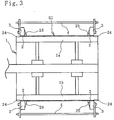
- both carcass fixing rings 3 are coupled with each other via a space adjusting plate 4 as illustrated in Fig. 3 .
- the space adjusting plate 4 is attached to the carcass fixing rings 3 using a fixing member such as a bolt.
- the segments 1a, 1b are moved in a radially-inward direction, and the primary making drum 1 is removed from the cylindrical-shaped primary molded body G1. Accordingly, the primary molded body G1 is in a state to be held by the fixing rings 2, the carcass fixing rings 3, and the space adjusting plate 4.
- a cylindrical-shaped inflation mold 5 is inserted inside the primary molded body G1 as illustrated in Fig. 4 .
- the inflation mold 5 has disc-shaped side plates 6 on both sides of a core portion 5a in the width direction thereof, while the core portion 5a is provided with multiple pressing plates 8 divided in the circumferential direction.
- the number of the pressing plates 8 is 5 in this embodiment, but it is not limited to 5.
- the side plates 6 are moved in the width direction by cylinders 6a provided in the core portion 5a. Expandable and contractible sealing members 7 are provided in the outer peripheral edge portions of the side plates 6.
- Each pressing plate 8 is configured to be moved in the radial direction by a cylinder 8a provided in the core portion 5a.
- the outer peripheral surface of the pressing plate 8 has approximately the same shape as the profile of the inner peripheral surface of the tire to be manufactured.
- the sealing members 7 are expanded so that the peripheral portions (the fixing rings 2 and the carcass fixing rings 3) of the bead rings 25 are securely fixed by the side plates 6. Subsequently, the space adjusting plate 4 is detached from the carcass fixing rings 3.
- each cylinder 6a is set free, and the rod of each cylinder 8a is extended to press the pressing plate 8 against the inner peripheral surface of the primary molded body G1, while slightly pressurizing the primary molded body G1 by injecting air a from the inner peripheral side so that the primary molded body G1 is expanded and deformed to the outer peripheral side.
- both bead rings 25 are moved so as to be closer to each other.
- a transfer and holding mold 9 is disposed on the outer peripheral side of the primary molded body G1.
- Suction means such as a vacuum pump is detachably connected to the transfer and holding mold 9.
- the transfer and holding mold 9 is formed with divided molds 9a which are divided in half in the width direction.
- the inner peripheral surface of the transfer and holding mold 9 is formed in an annular shape, and a large number of suction holes 10 communicating with the suction means are formed.
- the air a is further injected from the inner peripheral side of the primary molded body G1 to pressurize the primary molded body G1, while air A is sucked through the suction holes 10 of the transfer and holding mold 9 with the divided molds 9a assembled, so that the primary molded body G1 is sucked from the outer peripheral side.
- the primary molded body G1 is in a state to be sucked and held to the inner peripheral surface of the transfer and holding mold 9.
- the rods of cylinders 8a are contracted to retreat the pressing plate 8 and the sealing members 7 are contracted, whereby the inflation mold 5 is removed from the primary molded body G1. Suction of the primary molded body G1 by the transfer and holding mold is continued until the primary molded body G1 is transferred to a rigid inner mold 11.
- the cylindrical-shaped rigid inner mold 11 is inserted inside the primary molded body. Detailed structure of the rigid inner mold 11 is described later. Multiple divided bodies 12 divided in the circumferential direction are further divided in the width direction. Out of the resultant divided bodies 12, those on one side in the width direction are first moved around a rotation mechanism 13 as the rotation center in a radially-outward direction. Then, the divided bodies 12 on the other side are similarly moved and attached to the primary molded body G1 in an annular shape. With such attachment operation, the rigid inner mold 11 is inserted inside the primary molded body G1.
- the primary molded body G1 is set to be sucked and held to the inner peripheral surface of the transfer and holding mold 9, then is transferred to the outer peripheral surface of the rigid inner mold 11, and thus transfer operation can be performed smoothly without damaging the film 22 which serves as the inner layer.
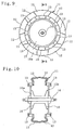
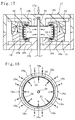
- the rigid inner mold 11 is in a cylindrical shape as illustrated in Figs. 9 and 10 , and includes the divided bodies 12 plurally divided in the circumferential direction.
- the divided bodies 12 are further divided in half in the width direction of the cylindrical-shaped peripheral surface.
- Examples of the material of the rigid inner mold 11 include metal such as aluminum and an aluminum alloy.
- These divided bodies 12 are fixed to peripheral edge portions of opposed disc-shaped supporting plates 15a, 15b via the rotation mechanisms 13, and are formed in a cylindrical shape. That is to say, out of the divided bodies 12 divided in half in the width direction of the cylindrical-shaped peripheral surface, those on one side in the width direction are disposed in an annular shape along the peripheral edge portion of the supporting plate 15a on one side out of the opposed supporting plates 15a, 15b, and out of the divided bodies 12 divided in half in the width direction of the cylindrical-shaped peripheral surface, those on the other side in the width direction are disposed in an annular shape along the peripheral edge portion of the supporting plate 15b on the other side.
- a central shaft 14 is fixed at the circle center position of the opposed supporting plates 15a, 15b to pass therethrough.
- the central shaft 14 and a pair of the supporting plates 15a, 15b are fixed to each other via a supporting rib 16 fixed on the outer peripheral surface of the central shaft 14.
- the rigid inner mold 11 including the multiple divided bodies 12 formed in a cylindrical shape is moved so that each divided body 12 is rotated in a diameter expanding or reducing direction around the rotation mechanism 13 as the rotation center.
- the cylindrical-shaped rigid inner mold 11, to which the primary molded body G1 is transferred, is mounted on a molding apparatus and the like with the central shaft 14 being supported in order to mold the green tire G.
- the opposite ends of the carcass material 24 in the width direction thereof are turned up on the rigid inner mold 11, while other tire constituting members such as the rubber member of the sidewall portion 26, the belt layers 27, the rubber member of the tread portion 28 are stacked on the outer peripheral surface of the primary molded body G1 so that the green tire G is molded as illustrated in Fig. 12 .
- the green tire G has no tread patterns formed thereon, but is formed in approximately the same size and shape as the pneumatic tire 21 to be manufactured.
- the rigid inner mold 11 is detached from the molded green tire G.
- the rotation mechanisms 13 of the divided bodies 12 are held from both sides in the width direction of the rigid inner mold 11, and engagement between the rotation mechanisms 13 and the supporting plates 15a, 15b is released.
- one supporting plate 15a is removed from the central shaft 14, then the supporting plate 15a and the other supporting plate 15b with fixed central shaft 14 are moved to the outside of the green tire G.
- the divided bodies 12 on one side in the width direction are rotated around the rotation mechanism 13 as the center toward the inside of the tire so that the cylindrical-shaped rigid inner mold 11 reduces its diameter.
- the divided bodies 12 on the other side in the width direction are rotated around the rotation mechanism 13 as the center toward the inside of the tire so that the cylindrical-shaped rigid inner mold 11 reduces its diameter.
- the divided bodies 12 are rotated toward the inside of the tire, then are moved to the outside of the green tire G to be detached.
- the reverse process of the process illustrated in Figs. 13 and 14 may be performed.
- the film 22 tends to be separated from the divided body 12. For this reason, compared with a pneumatic tire whose inner layer is formed of butyl rubber, the rigid inner mold 11 can be detached smoothly. Due to excellent release characteristics of the film 22, an additional work of, for example, applying release agent between the inner peripheral surface of the green tire and the rigid inner mold 11 (the divided bodies 12) is not required, which is advantageous to the improvement of productivity.
- molded green tire G is disposed at a predetermined position inside a curing mold installed in a curing apparatus 17.
- the curing mold includes multiple sectors 18a which are divided in the tire circumferential direction, and upper and lower annular side plates 18b, 18b.
- the lower side plate 18b is fixed in a bottom housing 17b in which each sector 18a is placed.
- a back segment 19 having an inclined surface is mounted on the rear surface of the sector 18a.
- a guide member 20 having an inclined surface and the upper side plate 18b are fixed in a top housing 17a.
- the bead portion below the green tire G is placed on the lower side plate 18b, and after the green tire G is positioned at a predetermined position, the top housing 17a is moved downward.
- the guide member 20 moves downward, and the inclined surface of the guide member 20 comes in contact with the inclined surface of the back segment 19.
- the sector 18a along with the back segment 19 gradually moves toward the central shaft 14. That is to say, the sectors 18a in a state of expanded diameter are moved in a radially-inward direction and are assembled to form an annular shape.
- the upper side plate 18b which is moved downward, is disposed at the upper inner peripheral edge portions of the sectors 18a assembled in an annular shape.
- the bead portion on the upper side of the green tire G comes in contact with the upper side plate 18b.
- the upper and lower bead portions of the green tire G are brought into close contact with and sealed to the upper and lower side plates 18b, respectively. Accordingly, the inner peripheral hollow portion of the green tire G is surrounded and sealed by the curing mold, the top housing 17a, and the bottom housing 17b.
- the curing mold is heated to a predetermined temperature, and heated fluid such as the heated air a is injected into the inner peripheral hollow portion of the green tire G through a communication path 29 provided in the bottom housing 17b.
- heated fluid such as the heated air a is injected into the inner peripheral hollow portion of the green tire G through a communication path 29 provided in the bottom housing 17b.
- the air a to be supplied examples include gas such as general air and nitrogen gas.
- the pressure for inflating the film 22 is, for example, approximately 0.01 MPa to 3.0 MPa.
- the film 22 is brought into close contact with and bonded to the inner peripheral surface of the tire (rubber members disposed in the outer peripheral side of the film 22) so that the pneumatic tire 21 having the film 22 as the inner layer is manufactured.
- the pneumatic tire 21 with excellent uniformity, having an inner layer which is light in weight and excels in air penetration preventing performance can be efficiently manufactured.
- the air A should be forcibly sucked from the inside of the curing mold to the outside so that the green tire G is cured in a negative pressure state.
- vacuum is drawn by a vacuum pump through the mating face of adjacent sectors (curing mold) 18a.
- the air between the stacked tire constituting members, or the air in the tire constituting members (rubber members) can be removed, and thus a problem due to trapped air in manufactured pneumatic tire 21 can be prevented, thereby its quality can be improved.
- an adhesive layer may be previously provided on the outer peripheral surface of the film 22.
- the tie rubber 23 is disposed to cover the entire outer peripheral surface of the film 22, but the tie rubber 23 may be disposed to cover a part of the outer peripheral surface of the film 22. If a certain bonding strength between the film 22 and the members on the outer peripheral side of the film 22 can be secured, the tie rubber 23 may be omitted.
- the film 22 serves as a conventional bladder, and thus maintenance of the bladder is not needed, which is advantageous to the improvement of productivity.
- the curing mold can be heated by various heat sources.
- an electric heating body embedded in the curing mold may be used. Heating by an electric heating body enables a precise temperature control.
- the outer peripheral surface of the green tire G is molded into a predetermined shape by the sector 18a, the inner peripheral surface is brought into contact with and molded by the inflated film 22. Accordingly, unlike the manufacturing method which uses a conventional bladder made of rubber, or the manufacturing method which presses the green tire on the outer peripheral surface of the rigid inner mold, no undesired marks are left on the inner peripheral surface of the cured pneumatic tire, whereby a smooth surface is created, and accordingly appearance quality is improved.
- the rigid inner mold 11 when the green tire G is cured, the rigid inner mold 11 is not disposed inside the curing mold, and thus the rigid inner mold 11 can be freely used during the curing. Consequently, the number of green tires G that can be molded by one rigid inner mold 11 within a predetermined time period increases, and thus productivity can be improved by effectively using the rigid inner mold 11. Accordingly, the number of the rigid inner molds 11 to be prepared can be reduced.
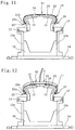
- the green tire G molded by using the rigid inner mold 11 can be cured using a bladder 31 as illustrated in Fig. 17 .
- Two disc-shaped bladder holding plates 32 are attached to a center post 30 which is inserted inside the tubular hole formed at the central portion of the top housing 17a and the bottom housing 17b.
- Elastic material such as rubber, or the bladder 31 formed by embedding reinforcing material such as a canvas layer into elastic material is fixed to the outer peripheral edge portion of the bladder holding plates 32.
- the bladder 31 is formed to have the same shape as the inner peripheral hollow portion of the green tire G when the bladder 31 is inflated. That is to say, the outside shape of the bladder 31 is formed in approximately the same size and shape as the inner peripheral hollow portion of the green tire G.
- the bladder 31 is placed in its contracted state in the inner peripheral hollow portion of the green tire G disposed in a predetermined position of the curing mold. Subsequently, the top housing 17a is moved downward, and the sectors 18a are assembled to form an annular shape.
- the upper side plate 18b which is moved downward, is disposed at the upper inner periphery portion of the sectors 18a assembled to form an annular shape. The upper bead portion comes in contact with the upper side plate 18b.
- the curing mold is heated to a predetermined temperature, while heated fluid such as the heated air a which is heated through a communication hole provided in the center post 30 is supplied to the bladder 31 and is expanded.
- heated fluid such as the heated air a which is heated through a communication hole provided in the center post 30 is supplied to the bladder 31 and is expanded.
- the film 22 is pressurized from the inner peripheral side to be inflated while being heated.
- the bladder 31 has approximately the same size and shape as the inner peripheral hollow portion of the green tire G, and thus is brought into close contact with the entire inner peripheral surface of the green tire G. However, the bladder 31 slightly presses against the inner peripheral surface of the green tire G (the film 22). In this manner, the film 22 is inflated, while being heated, and thus the green tire G is cured.
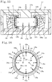
- the film 22 is inflated, and thus, as illustrated in Fig. 18 , unvulcanized rubber in the tire constituting members is pressed against the inner peripheral surface of the sector (curing mold) 18a, and accordingly, flows in the circumferential direction of the sector 18a. Consequently, even when non-uniformity in the volume of the tire constituting members of the green tire G exists, the non-uniformity can be corrected, and uniformity of the pneumatic tire 21 to be manufactured can be improved.
- the film 22 is brought into close contact with and bonded to the inner peripheral surface of the tire so that the pneumatic tire 21 having the film 22 as the inner layer is manufactured.
- the air A may be forcibly sucked from the inside of the curing mold to the outside so that the green tire G is cured in a negative pressure state.
- the bladder 31 is used, and thus heated fluid does not directly come in contact with the inner peripheral surface of the green tire G. Accordingly, various types of heated fluid can be used.
Description
- The present invention relates to a method for manufacturing a pneumatic tire, and more particularly to a method of manufacturing a pneumatic tire, which enables a pneumatic tire having excellent uniformity to be manufactured with high productivity by effectively using a rigid inner mold, the pneumatic tire having an inner layer which is light in weight and excels in air penetration preventing performance.
- Various methods of manufacturing a pneumatic tire, in which a green tire is molded on the outer peripheral surface of a metal rigid inner mold, and the molded green tire is placed inside a curing mold along with the rigid inner mold for curing, have been proposed (for example, see
Patent Document 1 and 2). - The document
US 2006/ 0169392 discloses a tire building system, which does not require prolonging tact time for tire building. Furthermore, the system does not need a specific occupying space for endless circulative traveling of a building carriage. The system includes workstations configured to mount applicable tire components onto a building drum. In this context, the building carriage is configured to support the building drum to thereby move the building drum among the respective workstations. - The invention in the document
US 4,684,422 relates to an apparatus for transferring a cylindrical band of elastomeric material to a tire building drum, or from one tire building drum to another building drum. The mentioned transfer apparatus discloses a hollow cylindrical housing having a pair of annular sealing and gripping means and preferably air operable bladders, which are located one at each end of the housing. The housing has a vacuum port located between the two annular gripping and sealing means so after said means seal against the outer side of the cylindrical component, air is evacuated through said port to retain the component in the housing. - The document
US 4,634,489 discloses a device for transferring an uncured tire carcass of cylindrical shape and comprising a cylindrical housing. Furthermore, it comprises a plurality of suction cups disposed in at least three circular bands around the housing. The said bands are located one at each end portion and one in a midportion of the housing and each cup is connected to an actuator for radial movement and is also connectable to a vacuum source. - The invention according to the document
US 4,007,080 relates to a device for transferring carcasses with core rings for raw pneumatic tires from a building-up station to a forming station by means of an annular holder which is variable in diameter, composed of segments and is adapted by means of suction cups to be placed on the substantially cylindrical outer surface of the carcass. The disclosed device for transferring a tire carcass from a tire building-up statio to a forming station has a cylindrical outer surface and is provided with core rings. The transfer is effected by means of an annular holder composed of segments and provided with suction cups adapted to be placed onto the outer substantially cylindrical surface of the carcass to be transferred for supporting the carcass. - The document
US 3,867,230 relates to an apparatus for shaping tires and more particularly to an apparatus for shaping a green tire carcass built in the so-called flat band form after which belts and tire tread may be placed thereon. In detail, the invention discloses a tire shaping apparatus for shaping into a toroidal form a green tire carcass built in the form of a flat band which utilizes a plurality of radially moveable supports having accordion-type pleated plates interconnected between the moveable supports, which expands a bladder supported thereon circumferentially uniformly to shape a tire carcass radially while moving the respective bead portions axially inwardly toward each other. - Finally, the document
US 2002/0033557 shows a method of inflation able to prevent peeling of an inner layer in a process of molding accompanied with inflation and deformation, in particular, a method of molding a hollow composite by giving deformation toward an inner surface of at least one composite member so as to cause it to laminate with another composite member, comprising giving the deformation and performing the molding by a pressurizing and heating medium. - The manufacturing method using such a rigid inner mold does not require a conventionally used bladder made of rubber, and can eliminates the process of, for example, detaching the molded green tire from a making drum. Moreover, compared with the case where a bladder is used for manufacturing, there is an advantage in that the inner peripheral surface of the cured tire can be formed into a predetermined shape with high precision.
- However, because the green tire is pressed by the curing mold from only the outside during the curing, the pressing force acting on the inner peripheral surface of the green tire is small. Accordingly, for example, even when non-uniformity in the volume of the tire constituting members exists on the inner peripheral surface of the tire, it is difficult to correct the non-uniformity, and thus improvement in uniformity of the cured tire is limited.
- In addition, when the inner peripheral surface of the green tire is pressed by the outer peripheral surface of the rigid inner mold, spaces between divided bodies forming the rigid inner mold leave marks on the inner peripheral surface of the cured tire, and thus there is a problem of reduced appearance quality.
- Furthermore, although butyl rubber is mainly used for an inner layer (innermost peripheral surface) of the green tire, an additional work of, for example, applying release agent is needed in order to easily release the inner layer from the outer peripheral surface of the rigid inner mold. Using an inner layer formed of butyl rubber is disadvantageous in reducing the tire weight because an inner layer formed of butyl rubber needs a certain thickness to secure sufficient air penetration preventing performance. For this reason, an inner layer which is light in weight and excels in air penetration preventing performance has been demanded.
- Furthermore, in the conventional manufacturing method using a rigid inner mold, the rigid inner mold is placed inside the curing mold along with the green tire during the curing, and thus there is a problem in that the rigid inner mold cannot be used for molding the green tire during the curing. Consequently, for example, in order to increase the production volume of tires, an accordingly large number of rigid inner molds are needed.
-
- Patent Document 1:
JP 2001 -88143A - Patent Document 2:
JP 2003 -340824A - Patent Document 3:
US 2006/0169392 - Patent Document 4:
US 4684422 - Patent Document 5:
US 4634489 - Patent Document 6:
US 4007080 - Patent Document 7:
US 3867230 - Patent Document 8:
US 2002/0033557 - An object of the present invention is to provide a method of manufacturing a pneumatic tire, which enables a pneumatic tire having excellent uniformity to be manufactured with high productivity by effectively using a rigid inner mold, the pneumatic tire having an inner layer which is light in weight and excels in air penetration preventing performance.
- The above-mentioned problem is solved by a method of manufacturing a pneumatic tire according to
claim 1. Advantageous effects of the present invention are achieved by the subject-matter of dependent claims. - A preferred embodiment of the method of manufacturing a pneumatic tire according to the present invention has features in that a primary molded body is formed by fitting bead rings on opposite ends, in a width direction, of a cylindrical-shaped body in which at least a carcass material is mounted on an outer peripheral side of a film formed of a thermoplastic resin or a thermoplastic elastomer composition obtained by blending a thermoplastic resin with an elastomer;
the primary molded body is expanded and deformed to the outer peripheral side by extending a pressing plate against the inner peripheral surface of the primary molded body, so that the bead rings are moved so as to be closer to each other;
the primary molded body is set to be sucked and held to an inner peripheral surface of a transfer and holding mold;
a cylindrical-shaped rigid inner mold including multiple divided bodies is inserted inside the primary molded body,
the rigid inner mold including divided bodies plurally is divided in the circumferential direction and further divided in half in the width direction of the cylindrical-shaped peripheral surface;
out of the resultant divided bodies first those on one side in the width direction are moved around a rotation mechanism as the rotation center in a radially-outward direction, then the divided bodies on the other side are moved, so that they are attached to the primary molded body in an annular shape, such that the rigid inner mold is inserted inside the primary molded body;
thereafter suction by the transfer and holding mold is stopped, and the primary molded body is transferred to an outer peripheral surface of the rigid inner mold; next, opposite ends of the carcass material in a width direction thereof are turned up on the rigid inner mold, while other tire constituting members are stacked on an outer peripheral surface of the primary molded body so that a green tire is molded; the rigid inner mold is detached from the green tire, thereafter the green tire is disposed inside a curing mold installed in a curing apparatus, and the curing mold is heated to a predetermined temperature; and the film is pressurized from an inner peripheral side to be inflated while being heated to cure the green tire, and the film is brought into close contact with and bonded to an inner peripheral surface of the tire. - Here, in order that the film is pressurized from an inner peripheral side to be inflated while being heated, for example, a bladder which, when being expanded, has a same shape as an inner peripheral hollow portion of the green tire is expanded by heated fluid in the inner peripheral hollow portion of the green tire disposed inside the curing mold.
- Alternatively, the film is pressurized to be inflated while being heated by injecting heated fluid directly into an inner peripheral surface of the green tire disposed inside the curing mold. In addition, in the present embodiment, when the primary molded body is sucked and held to the inner peripheral surface of the transfer and holding mold, it is also possible that the transfer and holding mold is disposed at an outer peripheral side of the primary molded body, and the primary molded body is pressurized from an inner peripheral side of the primary molded body, while the primary molded body is sucked by the transfer and holding mold from an outer peripheral side of the primary molded body.
- When the green tire is cured, the film is pressurized to be inflated from an inner peripheral side with a pressure of 0.01 MPa to 3.0 MPa. Moreover, for example, air is sucked from an inside of the curing mold to an outside, while a green tire disposed inside the curing mold is cured.
- According to a preferred embodiment of the method of manufacturing a pneumatic tire of the present invention, a primary molded body is formed by fitting bead rings on opposite ends, in the width direction, of a cylindrical-shaped body in which at least a carcass material is mounted on the outer peripheral side of a film formed of a thermoplastic resin or a thermoplastic elastomer composition; the primary molded body is set to be sucked and held to the inner peripheral surface of a transfer and holding mold; cylindrical-shaped rigid inner mold including multiple divided bodies is inserted inside the primary molded body; thereafter, suction by the transfer and holding mold is stopped; whereby the primary molded body can be smoothly transferred to the outer peripheral surface of the rigid inner mold without damaging the film on the inner peripheral surface.
- Next, the opposite ends of the above-mentioned carcass material in the width direction thereof are turned up on the rigid inner mold, while other tire constituting members are stacked on the outer peripheral surface of the primary molded body so that the green tire is molded; the rigid inner mold is detached from the green tire, and then the green tire is disposed inside a curing mold installed in a curing apparatus and is cured; thus the rigid inner mold can be freely used during the curing. Accordingly, the number of green tires that can be molded by one rigid inner mold within a predetermined time period increases, and thus productivity can be improved by effectively using the rigid inner mold.
- The green tire disposed inside the curing mold is cured after the curing mold is heated to a predetermined temperature, and the film is pressurized from the inner peripheral side to be inflated while being heated, and thus unvulcanized rubber of the tire constituting members is pressed against the inner peripheral surface of the curing mold and flows in the circumferential direction, whereby even when non-uniformity in the volume of the tire constituting members exists, the non-uniformity can be corrected. Accordingly, uniformity of the tires to be manufactured can be improved.
- Moreover, the green tire is cured, while the film is brought into close contact with and bonded to the inner peripheral surface of the tire to form an inner layer. This film is formed with a thermoplastic resin or a thermoplastic elastomer composition. For this reason, compared with the conventional inner layer which is formed of butyl rubber, the film is light in weight and has good gas barrier property, and thus manufactured tires are light in weight and have excellent air penetration preventing performance.
-
-
Fig. 1 is a vertical sectional view illustrating the process of molding a primary molded body. -
Fig. 2 is a cross-sectional view taken along A-A inFig. 1 . -
Fig. 3 is a vertical sectional view illustrating the state where a space adjusting plate is connected to carcass fixing rings inFig. 1 . -
Fig. 4 is an upper half vertical sectional view illustrating the state of inserting an inflation mold into the primary molded body. -
Fig. 5 is an upper half vertical sectional view illustrating the state of expanding and deforming the primary molded body toward the outer peripheral side. -
Fig. 6 is a vertical sectional view illustrating the internal structure of the inflation mold inFig. 4 . -
Fig. 7 is an upper half vertical sectional view illustrating the process of sucking and holding the primary molded body by a transfer and holding mold. -
Fig. 8 is an upper half vertical sectional view illustrating the process of inserting a rigid inner mold into the primary molded body. -
Fig. 9 is a front view of the rigid inner mold. -
Fig. 10 is a cross-sectional view taken along B-B inFig. 9 . -
Fig. 11 is an upper half vertical sectional view illustrating the rigid inner mold to which the primary molded body is transferred. -
Fig. 12 is an upper half vertical sectional view illustrating the state where a green tire is molded to the outer peripheral surface of the rigid inner mold. -
Fig. 13 is an upper half vertical sectional view illustrating the process of detaching the rigid inner mold from the molded green tire. -
Fig. 14 shows an upper half vertical sectional view illustrating the next process inFig. 13 . -
Fig. 15 is a vertical sectional view illustrating the state of curing the green tire. -
Fig. 16 is a cross-sectional view taken along C-C inFig. 15 . -
Fig. 17 is a vertical sectional view illustrating the state of curing the green tire using a bladder. -
Fig. 18 is a cross-sectional view taken along D-D inFig. 17 . -
Fig. 19 is a meridian half cross sectional view illustrating a pneumatic tire manufactured by the present embodiment. - Hereinafter, embodiments of the method of manufacturing a pneumatic tire according to the present invention are described based on the embodiments shown in the drawings. The same reference numerals are used for the same members before and after curing.
-
Fig. 19 illustrates apneumatic tire 21 manufactured by the present embodiment. In thepneumatic tire 21, acarcass material 24 is laid between a pair of bead rings 25, and thecarcass material 24 is folded back around abead core 25a from the inner side to the outer side. Atie rubber 23 and afilm 22 are stacked on the inner peripheral side of thecarcass material 24. Thefilm 22 on the innermost side is an inner layer which prevents air penetration, and thefilm 22 and thecarcass material 24 are bonded securely by thetie rubber 23 interposed therebetween. A rubber member forming asidewall portion 26, and a rubber member forming atread portion 28 are provided on the outer peripheral side of thecarcass material 24. - A
belt layer 27 is provided over the entire periphery in the tire circumferential direction on the outer peripheral side of thecarcass material 24 of thetread portion 28. A reinforcing cord forming thebelt layer 27 is disposed so as to be inclined to the tire circumferential direction, and stacked upper and lower belt layers 27 are disposed so that reinforcing cords thereof cross each other. Apneumatic tire 1 manufactured by the present embodiment is not limited to the structure shown inFig. 19 , and the present embodiment is applicable to the manufacture of a pneumatic tire with a different structure. - The
pneumatic tire 11 has a major structural feature in that the inner layer is formed of thefilm 22 in place of a conventional butyl rubber. The thickness of thefilm 22 is, for example, 0.005 mm to 0.2 mm. - The
film 22 used in the present embodiment includes a thermoplastic resin or a thermoplastic elastomer composition obtained by blending a thermoplastic resin with an elastomer. - Examples of the thermoplastic resin include: polyamide-based resins [for example, nylon 6 (N6), nylon 66 (N66), nylon 46 (N46), nylon 11 (N11), nylon 12 (N12), nylon 610 (N610), nylon 612 (N612), nylon 6/66 copolymers (N6/66), nylon 6/66/610 copolymers (N6/66/610), nylon MXD6,nylon 6T, nylon 6/6T copolymers, nylon 66/PP copolymers, and nylon 66/PPS copolymers]; polyester-based resins [for example, aromatic polyesters such as polybutylene terephthalate (PBT), polyethylene terephthalate (PET), polyethylene isophthalate (PEI), polybutylene terephthalate/tetramethylene glycol copolymer, PET/PEI copolymers, polyarylate (PAR), polybutylene naphthalate (PBN), liquid crystal polyester, and polyoxyalkylene diimide diacid/polybutylene terephthalate copolymers]; polynitrile-based resins [for example, polyacrylonitrile (PAN), polymethacrylonitrile, acrylonitrile/styrene copolymers (AS), methacrylonitrile/styrene copolymers, and methacrylonitrile/styrene/butadiene copolymer]; poly (meth) acrylate-based resin, [for example, poly methyl methacrylate (PMMA), polymethylmethacrylate, ethylene ethyl acrylate copolymer (EEA), ethylene acrylic acid copolymer (EAA), and ethylene methyl acrylate resin (EMA)]; polyvinyl-based resins [for example, vinyl acetate (EVA), polyvinyl alcohol (PVA), vinyl alcohol/ethylene copolymers (EVOH), polyvinylidene chloride (PVDC), polyvinyl chloride (PVC), vinyl chloride/vinylidene chloride copolymers, and vinylidene chloride/methyl acrylate copolymers]; cellulose-based resins [for example, cellulose acetate, and cellulose acetate butyrate]; fluororesins [for example, polyvinylidene fluoride (PVDF), polyvinyl fluoride (PVF), polychlorotrifluoroethylene (PCTFE), and tetrafluoroethylene/ethylene copolymers (ETFE)]; imide-based resins [for example, aromatic polyimide (PI)].
- Examples of the elastomer include: diene rubbers and their hydrogenated products [for example, NR, IR, epoxidized natural rubbers, SBR, BR (high-cis BR and low-cis BR), NBR, hydrogenated NBR, and hydrogenated SBR]; olefin-based rubbers [for example, ethylene propylene rubbers (EPDM and EPM), and maleic acid-modified ethylene propylene rubber (M-EPM); butyl rubber (IIR); copolymers of isoprene and aromatic vinyl or diene monomer; acrylic rubber (ACM); ionomers; halogen-containing rubbers [for example, Br-IIR, CI-IIR, brominated isobutylene para-methylstyrene copolymers (Br-IPMS), chloroprene rubber (CR), hydrin rubber (CHC and CHR), chlorosulfonated polyethylene (CSM), chlorinated polyethylene (CM), and maleic acid-modified chlorinated polyethylene (M-CM)]; silicone rubbers [for example, methyl vinyl silicone rubber, dimethyl silicone rubber, and methylphenylvinyl silicone rubber]; sulfur-containing rubbers [for example, polysulfide rubber]; fluororubbers [for example, vinylidene fluoride-based rubbers, fluorine-containing vinyl ether-based rubbers, tetrafluoroethylene propylene-based rubbers, fluorine-containing silicone-based rubbers, and fluorine-containing phosphazene-based rubbers]; thermoplastic elastomers [for example, styrene-based elastomers, olefin-based elastomers, polyester-based elastomers, urethane-based elastomers, and polyamide-based elastomers].
- In the thermoplastic elastomer composition used in the present embodiment, the weight ratio between a thermoplastic resin component (A) and an elastomer component (B) is determined as appropriate by the balance of the thickness and the flexibility of the film. For example, the weight ratio of the thermoplastic resin component (A) to the total weight of the thermoplastic resin component (A) and the elastomer component (B) is preferably 10% to 90%, and more preferably 20% to 85%.
- A compounding agent and other polymers such as a compatibilizer can be mixed to the thermoplastic elastomer composition used in the present embodiment as a third component in addition to the above-mentioned essential components (A) and (B). The purposes of mixing other polymers include: improvement of the compatibility between the thermoplastic resin component and the elastomer component, improvement of processability and formability of material into a film, improvement of heat resistance, and cost reduction. Examples of the materials used for these purposes include polyethylene, polypropylene, polystyrene, ABS, SBS, and polycarbonate.
- The
film 22 formed of the above-mentioned thermoplastic resin or the thermoplastic elastomer composition has excellent gas barrier property because it excels in the surface orientation of high-polymer chains. As shown above, in thepneumatic tire 21 manufactured by the present embodiment, thefilm 22 which has better gas barrier property than butyl rubber serves as the inner layer. Accordingly, compared with the conventional pneumatic tire, excellent air penetration preventing performance can be obtained. - Furthermore, the thickness of the inner layer formed of the conventional butyl rubber is, for example, 0.5 mm to 5.0 mm, but the thickness of the
film 22 is 0. 005 mm to 0.2 mm. Thus, the weight of the inner layer can be significantly reduced, and this reduction greatly contributes to reduction of the weight of thepneumatic tire 21. - The process of manufacturing the
pneumatic tire 21 is described below. - First, a primary molded body G1 is molded using a
primary making drum 1 illustrated inFigs. 1 and 2 . Theprimary making drum 1 is formed ofmultiple segments 1a, 1b which are divided in the circumferential direction, and two types ofsegments 1a, 1b are each movable in the radial direction. Accordingly, theprimary making drum 1 is a cylindrical body which is expandable and contractible. The number of thesegments 1a, 1b is 6 in this embodiment, but it is not limited to 6. - Fixing rings 2 are fitted on opposite ends, in the width direction, of the
primary making drum 1, and each segment 1a is moved in a radially-outward direction to make theprimary making drum 1 into a cylindrical shape. Thefilm 22, thetie rubber 23, and thecarcass material 24 are placed so as to be stacked in this order on the outer peripheral surface of theprimary making drum 1 which is made into a cylindrical shape, whereby a cylindrical-shaped body is formed. Thecarcass material 24 projects out from thefilm 22 and thetie rubber 23 at both sides in the width direction. - In the case where the
film 22 preformed in a tubular shape is used, thetubular film 22 is fitted on theprimary making drum 1 to form a cylindrical-shaped body. In the case where strip-shapedfilm 22 is used, the strip-shapedfilm 22 is wrapped around the outer peripheral surface of theprimary making drum 1 to form a cylindrical-shaped body. In the latter case, the strip-shapedfilm 22 and thetie rubber 23, or the strip-shapedfilm 22, thetie rubber 23, and thecarcass material 24 are pre-stacked to form a stacked body, then the stacked body can be wrapped around the outer peripheral surface of theprimary making drum 1 to form a cylindrical-shaped body. - Next, the bead rings 25 are disposed on the opposite ends of the
carcass material 24 in the width direction thereof on the outer peripheral side. Then, the carcass fixing rings 3 are disposed on the opposite ends of thecarcass material 24 in the width direction thereof on the outer peripheral side. Thus, the opposite ends of thecarcass material 24 in the width direction thereof are fixed by being sandwiched between the fixingrings 2 and the carcass fixing rings 3. The bead rings 25 are fixed on the inner sides of the carcass fixing rings 3. In this manner, the primary molded body G1 is molded by fitting the bead rings 25 on the opposite ends, in the width direction, of a cylindrical-shaped body in which at least thecarcass material 24 is mounted on the outer peripheral side of thefilm 22. - Next, both carcass fixing rings 3 are coupled with each other via a
space adjusting plate 4 as illustrated inFig. 3 . Thespace adjusting plate 4 is attached to the carcass fixing rings 3 using a fixing member such as a bolt. - Next, the
segments 1a, 1b are moved in a radially-inward direction, and theprimary making drum 1 is removed from the cylindrical-shaped primary molded body G1. Accordingly, the primary molded body G1 is in a state to be held by the fixing rings 2, the carcass fixing rings 3, and thespace adjusting plate 4. - Next, a cylindrical-shaped
inflation mold 5 is inserted inside the primary molded body G1 as illustrated inFig. 4 . As illustrated inFigs. 4 and6 , theinflation mold 5 has disc-shapedside plates 6 on both sides of acore portion 5a in the width direction thereof, while thecore portion 5a is provided with multiplepressing plates 8 divided in the circumferential direction. Although the number of thepressing plates 8 is 5 in this embodiment, but it is not limited to 5. - The
side plates 6 are moved in the width direction bycylinders 6a provided in thecore portion 5a. Expandable andcontractible sealing members 7 are provided in the outer peripheral edge portions of theside plates 6. - Each
pressing plate 8 is configured to be moved in the radial direction by acylinder 8a provided in thecore portion 5a. The outer peripheral surface of thepressing plate 8 has approximately the same shape as the profile of the inner peripheral surface of the tire to be manufactured. - After the
inflation mold 5 is inserted inside the primary molded body G1, the sealingmembers 7 are expanded so that the peripheral portions (the fixing rings 2 and the carcass fixing rings 3) of the bead rings 25 are securely fixed by theside plates 6. Subsequently, thespace adjusting plate 4 is detached from the carcass fixing rings 3. - Next, as illustrated in
Fig. 5 , eachcylinder 6a is set free, and the rod of eachcylinder 8a is extended to press thepressing plate 8 against the inner peripheral surface of the primary molded body G1, while slightly pressurizing the primary molded body G1 by injecting air a from the inner peripheral side so that the primary molded body G1 is expanded and deformed to the outer peripheral side. At this point, both bead rings 25 (the side plates 6) are moved so as to be closer to each other. - Next, as illustrated in
Fig. 7 , a transfer and holdingmold 9 is disposed on the outer peripheral side of the primary molded body G1. Suction means such as a vacuum pump is detachably connected to the transfer and holdingmold 9. The transfer and holdingmold 9 is formed with dividedmolds 9a which are divided in half in the width direction. The inner peripheral surface of the transfer and holdingmold 9 is formed in an annular shape, and a large number of suction holes 10 communicating with the suction means are formed. - Next, the air a is further injected from the inner peripheral side of the primary molded body G1 to pressurize the primary molded body G1, while air A is sucked through the suction holes 10 of the transfer and holding
mold 9 with the dividedmolds 9a assembled, so that the primary molded body G1 is sucked from the outer peripheral side. Thereby, the primary molded body G1 is in a state to be sucked and held to the inner peripheral surface of the transfer and holdingmold 9. Subsequently, the rods ofcylinders 8a are contracted to retreat thepressing plate 8 and the sealingmembers 7 are contracted, whereby theinflation mold 5 is removed from the primary molded body G1. Suction of the primary molded body G1 by the transfer and holding mold is continued until the primary molded body G1 is transferred to a rigidinner mold 11. - Next, as illustrated in
Fig. 8 , the cylindrical-shaped rigidinner mold 11 is inserted inside the primary molded body. Detailed structure of the rigidinner mold 11 is described later. Multiple dividedbodies 12 divided in the circumferential direction are further divided in the width direction. Out of the resultant dividedbodies 12, those on one side in the width direction are first moved around arotation mechanism 13 as the rotation center in a radially-outward direction. Then, the dividedbodies 12 on the other side are similarly moved and attached to the primary molded body G1 in an annular shape. With such attachment operation, the rigidinner mold 11 is inserted inside the primary molded body G1. - Subsequently, suction by the transfer and holding
mold 9 is stopped, and the primary molded body G1 is transferred to the outer peripheral surface of the rigidinner mold 11. After the primary molded body G1 is transferred, the transfer and holdingmold 9 is separated into dividedmolds 9a, and detached from the primary molded body G1. - In this way, according to the present embodiment, the primary molded body G1 is set to be sucked and held to the inner peripheral surface of the transfer and holding
mold 9, then is transferred to the outer peripheral surface of the rigidinner mold 11, and thus transfer operation can be performed smoothly without damaging thefilm 22 which serves as the inner layer. - The rigid
inner mold 11 is in a cylindrical shape as illustrated inFigs. 9 and 10 , and includes the dividedbodies 12 plurally divided in the circumferential direction. The dividedbodies 12 are further divided in half in the width direction of the cylindrical-shaped peripheral surface. Examples of the material of the rigidinner mold 11 include metal such as aluminum and an aluminum alloy. - These divided
bodies 12 are fixed to peripheral edge portions of opposed disc-shaped supportingplates rotation mechanisms 13, and are formed in a cylindrical shape. That is to say, out of the dividedbodies 12 divided in half in the width direction of the cylindrical-shaped peripheral surface, those on one side in the width direction are disposed in an annular shape along the peripheral edge portion of the supportingplate 15a on one side out of the opposed supportingplates bodies 12 divided in half in the width direction of the cylindrical-shaped peripheral surface, those on the other side in the width direction are disposed in an annular shape along the peripheral edge portion of the supportingplate 15b on the other side. - A
central shaft 14 is fixed at the circle center position of the opposed supportingplates central shaft 14 and a pair of the supportingplates rib 16 fixed on the outer peripheral surface of thecentral shaft 14. As described later, the rigidinner mold 11 including the multiple dividedbodies 12 formed in a cylindrical shape is moved so that each dividedbody 12 is rotated in a diameter expanding or reducing direction around therotation mechanism 13 as the rotation center. - Next, as illustrated in
Fig. 11 , the cylindrical-shaped rigidinner mold 11, to which the primary molded body G1 is transferred, is mounted on a molding apparatus and the like with thecentral shaft 14 being supported in order to mold the green tire G. - The opposite ends of the
carcass material 24 in the width direction thereof are turned up on the rigidinner mold 11, while other tire constituting members such as the rubber member of thesidewall portion 26, the belt layers 27, the rubber member of thetread portion 28 are stacked on the outer peripheral surface of the primary molded body G1 so that the green tire G is molded as illustrated inFig. 12 . The green tire G has no tread patterns formed thereon, but is formed in approximately the same size and shape as thepneumatic tire 21 to be manufactured. - Next, the rigid
inner mold 11 is detached from the molded green tire G. In order to detach the rigidinner mold 11, first, as illustrated inFig. 13 , therotation mechanisms 13 of the dividedbodies 12 are held from both sides in the width direction of the rigidinner mold 11, and engagement between therotation mechanisms 13 and the supportingplates plate 15a is removed from thecentral shaft 14, then the supportingplate 15a and the other supportingplate 15b with fixedcentral shaft 14 are moved to the outside of the green tire G. - Next, as illustrated in
Fig. 14 , the dividedbodies 12 on one side in the width direction (right side inFig. 14 ) are rotated around therotation mechanism 13 as the center toward the inside of the tire so that the cylindrical-shaped rigidinner mold 11 reduces its diameter. Subsequently, the dividedbodies 12 on the other side in the width direction (left side inFig. 14 ), are rotated around therotation mechanism 13 as the center toward the inside of the tire so that the cylindrical-shaped rigidinner mold 11 reduces its diameter. In this manner, the dividedbodies 12 are rotated toward the inside of the tire, then are moved to the outside of the green tire G to be detached. In order to insert the rigidinner mold 11 inside the green tire G, the reverse process of the process illustrated inFigs. 13 and 14 may be performed. - The
film 22 tends to be separated from the dividedbody 12. For this reason, compared with a pneumatic tire whose inner layer is formed of butyl rubber, the rigidinner mold 11 can be detached smoothly. Due to excellent release characteristics of thefilm 22, an additional work of, for example, applying release agent between the inner peripheral surface of the green tire and the rigid inner mold 11 (the divided bodies 12) is not required, which is advantageous to the improvement of productivity. - Next, as illustrated in
Fig. 15 , molded green tire G is disposed at a predetermined position inside a curing mold installed in acuring apparatus 17. The curing mold includesmultiple sectors 18a which are divided in the tire circumferential direction, and upper and lowerannular side plates - The
lower side plate 18b is fixed in abottom housing 17b in which eachsector 18a is placed. Aback segment 19 having an inclined surface is mounted on the rear surface of thesector 18a. Aguide member 20 having an inclined surface and theupper side plate 18b are fixed in atop housing 17a. - The bead portion below the green tire G is placed on the
lower side plate 18b, and after the green tire G is positioned at a predetermined position, thetop housing 17a is moved downward. Along with this downward movement, theguide member 20 moves downward, and the inclined surface of theguide member 20 comes in contact with the inclined surface of theback segment 19. As theguide member 20 moves downward, thesector 18a along with theback segment 19 gradually moves toward thecentral shaft 14. That is to say, thesectors 18a in a state of expanded diameter are moved in a radially-inward direction and are assembled to form an annular shape. Then theupper side plate 18b, which is moved downward, is disposed at the upper inner peripheral edge portions of thesectors 18a assembled in an annular shape. The bead portion on the upper side of the green tire G comes in contact with theupper side plate 18b. - The upper and lower bead portions of the green tire G are brought into close contact with and sealed to the upper and
lower side plates 18b, respectively. Accordingly, the inner peripheral hollow portion of the green tire G is surrounded and sealed by the curing mold, thetop housing 17a, and thebottom housing 17b. - Next, the curing mold is heated to a predetermined temperature, and heated fluid such as the heated air a is injected into the inner peripheral hollow portion of the green tire G through a
communication path 29 provided in thebottom housing 17b. By injecting heated fluid directly into the inner peripheral surface of the film 22 (inner peripheral hollow portion) in this manner, thefilm 22 is pressurized to be inflated while being heated to cure the green tire G. - Examples of the air a to be supplied include gas such as general air and nitrogen gas. Moreover, the pressure for inflating the
film 22 is, for example, approximately 0.01 MPa to 3.0 MPa. - By inflating the
film 22, unvulcanized rubber in the tire constituting members is pressed against the inner peripheral surface of the sector (curing mold) 18a as illustrated inFig. 16 , and accordingly flows in the circumferential direction of thesector 18a. Consequently, even when non-uniformity in the volume of the tire constituting members of the green tire G exists, the non-uniformity can be corrected, and uniformity of thepneumatic tire 21 to be manufactured can be improved. - Along with the curing of the green tire G, the
film 22 is brought into close contact with and bonded to the inner peripheral surface of the tire (rubber members disposed in the outer peripheral side of the film 22) so that thepneumatic tire 21 having thefilm 22 as the inner layer is manufactured. In this manner, thepneumatic tire 21 with excellent uniformity, having an inner layer which is light in weight and excels in air penetration preventing performance can be efficiently manufactured. - At the time of curing, it is preferable that the air A should be forcibly sucked from the inside of the curing mold to the outside so that the green tire G is cured in a negative pressure state. For example, vacuum is drawn by a vacuum pump through the mating face of adjacent sectors (curing mold) 18a. In this manner, the air between the stacked tire constituting members, or the air in the tire constituting members (rubber members) can be removed, and thus a problem due to trapped air in manufactured
pneumatic tire 21 can be prevented, thereby its quality can be improved. - In order to increase the bonding power between the
film 22 and the inner peripheral surface of the tire, an adhesive layer may be previously provided on the outer peripheral surface of thefilm 22. Thetie rubber 23 is disposed to cover the entire outer peripheral surface of thefilm 22, but thetie rubber 23 may be disposed to cover a part of the outer peripheral surface of thefilm 22. If a certain bonding strength between thefilm 22 and the members on the outer peripheral side of thefilm 22 can be secured, thetie rubber 23 may be omitted. - In this embodiment, the
film 22 serves as a conventional bladder, and thus maintenance of the bladder is not needed, which is advantageous to the improvement of productivity. - The curing mold can be heated by various heat sources. For example, an electric heating body embedded in the curing mold may be used. Heating by an electric heating body enables a precise temperature control.
- In this curing process, the outer peripheral surface of the green tire G is molded into a predetermined shape by the
sector 18a, the inner peripheral surface is brought into contact with and molded by theinflated film 22. Accordingly, unlike the manufacturing method which uses a conventional bladder made of rubber, or the manufacturing method which presses the green tire on the outer peripheral surface of the rigid inner mold, no undesired marks are left on the inner peripheral surface of the cured pneumatic tire, whereby a smooth surface is created, and accordingly appearance quality is improved. - Moreover, when the green tire G is cured, the rigid
inner mold 11 is not disposed inside the curing mold, and thus the rigidinner mold 11 can be freely used during the curing. Consequently, the number of green tires G that can be molded by one rigidinner mold 11 within a predetermined time period increases, and thus productivity can be improved by effectively using the rigidinner mold 11. Accordingly, the number of the rigidinner molds 11 to be prepared can be reduced. - The green tire G molded by using the rigid
inner mold 11 can be cured using abladder 31 as illustrated inFig. 17 . Two disc-shapedbladder holding plates 32 are attached to acenter post 30 which is inserted inside the tubular hole formed at the central portion of thetop housing 17a and thebottom housing 17b. Elastic material such as rubber, or thebladder 31 formed by embedding reinforcing material such as a canvas layer into elastic material is fixed to the outer peripheral edge portion of thebladder holding plates 32. - The
bladder 31 is formed to have the same shape as the inner peripheral hollow portion of the green tire G when thebladder 31 is inflated. That is to say, the outside shape of thebladder 31 is formed in approximately the same size and shape as the inner peripheral hollow portion of the green tire G. - To cure the green tire G, the
bladder 31 is placed in its contracted state in the inner peripheral hollow portion of the green tire G disposed in a predetermined position of the curing mold. Subsequently, thetop housing 17a is moved downward, and thesectors 18a are assembled to form an annular shape. Theupper side plate 18b, which is moved downward, is disposed at the upper inner periphery portion of thesectors 18a assembled to form an annular shape. The upper bead portion comes in contact with theupper side plate 18b. - Next, the curing mold is heated to a predetermined temperature, while heated fluid such as the heated air a which is heated through a communication hole provided in the
center post 30 is supplied to thebladder 31 and is expanded. By the expandedbladder 31, thefilm 22 is pressurized from the inner peripheral side to be inflated while being heated. - The
bladder 31 has approximately the same size and shape as the inner peripheral hollow portion of the green tire G, and thus is brought into close contact with the entire inner peripheral surface of the green tire G. However, thebladder 31 slightly presses against the inner peripheral surface of the green tire G (the film 22). In this manner, thefilm 22 is inflated, while being heated, and thus the green tire G is cured. - In this embodiment also, the
film 22 is inflated, and thus, as illustrated inFig. 18 , unvulcanized rubber in the tire constituting members is pressed against the inner peripheral surface of the sector (curing mold) 18a, and accordingly, flows in the circumferential direction of thesector 18a. Consequently, even when non-uniformity in the volume of the tire constituting members of the green tire G exists, the non-uniformity can be corrected, and uniformity of thepneumatic tire 21 to be manufactured can be improved. Thefilm 22 is brought into close contact with and bonded to the inner peripheral surface of the tire so that thepneumatic tire 21 having thefilm 22 as the inner layer is manufactured. - In this embodiment also, at the time of curing, the air A may be forcibly sucked from the inside of the curing mold to the outside so that the green tire G is cured in a negative pressure state.
- In the case of this embodiment, the
bladder 31 is used, and thus heated fluid does not directly come in contact with the inner peripheral surface of the green tire G. Accordingly, various types of heated fluid can be used. - In the above-mentioned various embodiments, the cases where radial tires are manufactured are taken as examples, however, the present invention can be even applied to the case of manufacturing bias tires.
-
- 1
- primary making drum
- 1a, 1b
- segment
- 2
- fixing ring
- 3
- carcass fixing ring
- 4
- space adjusting plate
- 5
- inflation mold
- 8
- pressing plate
- 9
- transfer and holding mold
- 9a
- divided mold
- 10
- suction hole
- 11
- rigid inner mold
- 12
- divided body
- 17
- curing apparatus
- 18a
- sector
- 18b
- side plate
- 21
- pneumatic tire
- 22
- film
- 23
- tie rubber
- 24
- carcass material
- 25
- bead ring
- 26
- sidewall portion
- 27
- belt layer
- 28
- tread portion
- 30
- center post
- 31
- bladder
- G1
- primary molded body
- G
- green tire
Claims (6)
- A method of manufacturing a pneumatic tire (21), comprising the steps of:forming a primary molded body (G1) by fitting bead rings (25) on opposite ends, in a width direction, of a cylindrical-shaped body in which at least a carcass material (24) is mounted on an outer peripheral side of a film (22) formed of a thermoplastic resin or a thermoplastic elastomer composition obtained by blending a thermoplastic resin with an elastomer;expanding and deforming the primary molded body (G1) to the outer peripheral side by extending a pressing plate (8) against the inner peripheral surface of the primary molded body (G1), so that the bead rings (25) are moved so as to be closer to each other;setting the primary molded body (G1) so as to be sucked and held to an inner peripheral surface of a transfer-holding mold (9);inserting a cylindrical-shaped rigid inner mold (11) including multiple divided bodies (12) into the inside of the primary molded body (G1),the rigid inner mold (11) including divided bodies (12) plurally divided in the circumferential direction and further divided in half in the width direction of the cylindrical-shaped peripheral surface;out of the resultant divided bodies (12) moving first those on one side in the width direction around a rotation mechanism as the rotation center in a radially-outward direction, then moving the divided bodies (12) on the other side, so that they are attached to the primary molded body (G1) in an annular shape, such that the rigid inner mold (11) is inserted inside the primary molded body (G1);stopping suction by the transfer-holding mold (9), and transferring the primary molded body (G1) to an outer peripheral surface of the rigid inner mold (11);turning up opposite ends of the carcass material (24) in a width direction thereof on the rigid inner mold (11), while other tire constituting members are being stacked on an outer peripheral surface of the primary molded body (G1) so that a green tire (G) is molded;detaching the rigid inner mold (11) from the green tire (G);disposing the green tire (G) inside of a curing mold installed in a curing apparatus (17), and heating the curing mold to a predetermined temperature; andpressurizing the film (22) from an inner peripheral side to inflate the film (22) while heating the curing mold to cure the green tire (G), and bringing the film (22) into close contact with and bonded to an inner peripheral surface of the tire.
- The method of manufacturing a pneumatic tire according to claim 1, comprising
expanding a bladder (31) by heated fluid in the inner peripheral hollow portion of the green tire (G) disposed inside the curing mold in such a way that the film (22) can be pressurized from an inner peripheral side to be inflated while being heated,
the outside shape of the bladder (31) being formed in approximately the same size and shape as the inner peripheral hollow portion of the green tire (G)
such that the bladder (31) has the same shape as an inner peripheral hollow portion of the green tire (G) when being expanded. - The method of manufacturing a pneumatic tire (21) according to claim 1, comprising
injecting heated fluid directly into an inner peripheral surface of the green tire (G) disposed inside the curing mold in such a way that the film (22) can be pressurized to be inflated while being heated. - The method of manufacturing a pneumatic tire (21) according to any one of claims 1 to 3, comprising
disposing the transfer-holding mold (9) at an outer peripheral side of the primary molded body (G1) when the primary molded body (G1) is being sucked and held to the inner peripheral surface of the transfer-holding mold (9), and
pressurizing the primary molded body (G1) from an inner peripheral side of the primary molded body (G1), while the primary molded body (G1) is being sucked by the transfer-holding mold (9) from an outer peripheral side of the primary molded body (G1). - The method of manufacturing a pneumatic tire (21) according to any one of claims 1 to 4, comprising
pressurizing the film (22) so as to be inflated from an inner peripheral side with a pressure of 0.01 MPa to 3.0 MPa when the green tire (G) is cured. - The method of manufacturing a pneumatic tire (21) according to any one of claims 1 to 5, comprising
sucking air from an inside of the curing mold to outside thereof, while a green tire (G) disposed inside the curing mold is being cured.
Applications Claiming Priority (2)
| Application Number | Priority Date | Filing Date | Title |
|---|---|---|---|
| JP2009112877A JP4816761B2 (en) | 2009-05-07 | 2009-05-07 | Pneumatic tire manufacturing method |
| PCT/JP2009/061053 WO2010128565A1 (en) | 2009-05-07 | 2009-06-17 | Method of manufacturing pneumatic tire |
Publications (3)
| Publication Number | Publication Date |
|---|---|
| EP2431162A1 EP2431162A1 (en) | 2012-03-21 |
| EP2431162A4 EP2431162A4 (en) | 2012-12-26 |
| EP2431162B1 true EP2431162B1 (en) | 2016-03-02 |
Family
ID=43050078
Family Applications (1)
| Application Number | Title | Priority Date | Filing Date |
|---|---|---|---|
| EP09844352.6A Not-in-force EP2431162B1 (en) | 2009-05-07 | 2009-06-17 | Method of manufacturing pneumatic tires |
Country Status (6)
| Country | Link |
|---|---|
| US (1) | US8652394B2 (en) |
| EP (1) | EP2431162B1 (en) |
| JP (1) | JP4816761B2 (en) |
| KR (1) | KR101286519B1 (en) |
| CN (1) | CN102421588B (en) |
| WO (1) | WO2010128565A1 (en) |
Families Citing this family (6)
| Publication number | Priority date | Publication date | Assignee | Title |
|---|---|---|---|---|
| JP4853576B2 (en) * | 2010-03-30 | 2012-01-11 | 横浜ゴム株式会社 | Pneumatic tire manufacturing method |
| JP4853577B2 (en) * | 2010-03-30 | 2012-01-11 | 横浜ゴム株式会社 | Pneumatic tire manufacturing method |
| JP5714193B1 (en) * | 2013-07-18 | 2015-05-07 | 三井化学株式会社 | Metal / resin composite structure and metal member |
| RU2678662C1 (en) * | 2013-11-26 | 2019-01-30 | Пирелли Тайр С.П.А. | Method, process and plant for building tyres |
| MX2018007498A (en) | 2015-12-28 | 2018-09-18 | Pirelli | Process and plant for building tyres. |
| CN116494509B (en) * | 2023-06-28 | 2023-09-08 | 西南石油大学 | Basalt fiber composite pipe preparation mold |
Family Cites Families (34)
| Publication number | Priority date | Publication date | Assignee | Title |
|---|---|---|---|---|
| US3867230A (en) * | 1973-02-08 | 1975-02-18 | Goodrich Co B F | Tire building machine |
| DE2409586B2 (en) * | 1974-02-28 | 1976-12-09 | Zusatz in: 25 05 486 Continental Gummi-Werke AG, 3000 Hannover | DEVICE FOR TRANSFERRING A CARCASS COVERED WITH CORE RINGS FOR BLANK TIRE TIRES |
| JPS5878740A (en) * | 1981-11-02 | 1983-05-12 | Sumitomo Rubber Ind Ltd | Method and apparatus for manufacturing tire |
| IT1151126B (en) * | 1982-03-30 | 1986-12-17 | Pirelli | TIRE PROCESSING AND EQUIPMENT |
| US4634489A (en) * | 1984-07-18 | 1987-01-06 | The Goodyear Tire & Rubber Company | Device for transferring a tire carcass band |
| EP0190532B1 (en) * | 1985-02-05 | 1989-10-04 | The Goodyear Tire & Rubber Company | A transfer apparatus for tire carcasses and tire bands |
| GB8724849D0 (en) * | 1987-10-23 | 1987-11-25 | Apsley Metals Ltd | Manufacture of tyres |
| US6332999B1 (en) * | 1998-07-31 | 2001-12-25 | Pirelli Pneumatici S.P.A. | Method and apparatus for moulding and curing tires for vehicle wheels |
| US7597837B2 (en) * | 1999-06-25 | 2009-10-06 | Pirelli Pneumatici S.P.A. | Method and apparatus for moulding and curing tyres for vehicle wheels |
| EP1075929B1 (en) | 1999-08-10 | 2004-05-26 | Sedepro | Rigid core in two parts, for manufacturing tires |
| US6673184B1 (en) * | 2000-02-23 | 2004-01-06 | The Goodyear Tire & Rubber Company | Tire and method for correcting tire uniformity thereof |
| US6651716B1 (en) * | 2000-02-23 | 2003-11-25 | The Goodyear Tire & Rubber Company | Method and tire adapted for post cure tire uniformity correction |
| US6740280B1 (en) * | 2000-04-10 | 2004-05-25 | The Goodyear Tire & Rubber Company | Tire construction method for improving tire uniformity |
| JP4367593B2 (en) * | 2000-05-08 | 2009-11-18 | 横浜ゴム株式会社 | Tire vulcanizer and tire vulcanizing method |
| JP4496614B2 (en) * | 2000-07-18 | 2010-07-07 | 横浜ゴム株式会社 | Inflation molding method for tires using hot air or hot gas |
| DE60334090D1 (en) * | 2002-02-25 | 2010-10-21 | Bridgestone Corp | VULCANIZING TOOL FOR SHAPED ARTICLES IN RUBBER |
| JP2003245928A (en) * | 2002-02-25 | 2003-09-02 | Bridgestone Corp | Method for cleaning mold for vulcanizing rubber molded component |
| JP2003340824A (en) | 2002-05-27 | 2003-12-02 | Bridgestone Corp | Method for vulcanizing and molding tire, and mold for molding tire |
| EP1568475B1 (en) * | 2002-11-25 | 2014-02-12 | Bridgestone Corporation | Tire building system and tire manufacturing method using this system |
| CN100522534C (en) * | 2003-07-25 | 2009-08-05 | 不二商事株式会社 | Tire vulcanizing method and vulcanizer for performing the method |
| JP2005219565A (en) * | 2004-02-04 | 2005-08-18 | Yokohama Rubber Co Ltd:The | Pneumatic tire |
| JP2005297478A (en) * | 2004-04-15 | 2005-10-27 | Yokohama Rubber Co Ltd:The | Manufacturing method for pneumatic tire |
| US7128545B2 (en) * | 2004-08-23 | 2006-10-31 | The Goodyear Tire & Rubber Company | Tire curing bladder |
| JP4715362B2 (en) * | 2005-07-27 | 2011-07-06 | 横浜ゴム株式会社 | Inner liner for tire and pneumatic tire using the same |
| JP4735124B2 (en) * | 2005-08-17 | 2011-07-27 | 横浜ゴム株式会社 | Pneumatic tire manufacturing method |
| JP4004518B2 (en) * | 2005-10-04 | 2007-11-07 | 横浜ゴム株式会社 | Pneumatic tire using rubber laminate |
| JP4853067B2 (en) * | 2006-03-22 | 2012-01-11 | 横浜ゴム株式会社 | Separation / extraction method and separation / extraction apparatus for rigid core for tire molding |
| BRPI0621799B1 (en) * | 2006-07-11 | 2017-06-06 | Pirelli | process and apparatus for producing tires |
| JP2008044204A (en) * | 2006-08-14 | 2008-02-28 | Yokohama Rubber Co Ltd:The | Vulcanization process of pneumatic tire |
| US7780807B2 (en) * | 2006-11-03 | 2010-08-24 | The Goodyear Tire & Rubber Company | Air shaping of green tire carcass |
| FR2917992B1 (en) * | 2007-06-28 | 2012-08-10 | Michelin Soc Tech | METHOD FOR APPLYING A LAYER OF MATERIAL INSIDE A PNEUMATIC TIRE FOR CYCLE |
| JP2009018445A (en) * | 2007-07-10 | 2009-01-29 | Yokohama Rubber Co Ltd:The | Method of manufacturing pneumatic tire |
| JP2009029035A (en) * | 2007-07-27 | 2009-02-12 | Yokohama Rubber Co Ltd:The | Tire manufacturing method and tire vulcanizer |
| JP4297290B2 (en) * | 2007-12-21 | 2009-07-15 | 横浜ゴム株式会社 | Pneumatic tire manufacturing method |
-
2009
- 2009-05-07 JP JP2009112877A patent/JP4816761B2/en not_active Expired - Fee Related
- 2009-06-17 CN CN200980159138.3A patent/CN102421588B/en not_active Expired - Fee Related
- 2009-06-17 KR KR1020117026706A patent/KR101286519B1/en not_active IP Right Cessation
- 2009-06-17 EP EP09844352.6A patent/EP2431162B1/en not_active Not-in-force
- 2009-06-17 US US13/318,196 patent/US8652394B2/en not_active Expired - Fee Related
- 2009-06-17 WO PCT/JP2009/061053 patent/WO2010128565A1/en active Application Filing
Also Published As
| Publication number | Publication date |
|---|---|
| JP2010260266A (en) | 2010-11-18 |
| CN102421588A (en) | 2012-04-18 |
| EP2431162A1 (en) | 2012-03-21 |
| US8652394B2 (en) | 2014-02-18 |
| KR20120011869A (en) | 2012-02-08 |
| JP4816761B2 (en) | 2011-11-16 |
| WO2010128565A1 (en) | 2010-11-11 |
| EP2431162A4 (en) | 2012-12-26 |
| KR101286519B1 (en) | 2013-07-16 |
| CN102421588B (en) | 2014-05-28 |
| US20120049418A1 (en) | 2012-03-01 |
Similar Documents
| Publication | Publication Date | Title |
|---|---|---|
| EP2221159B1 (en) | Process for producing a pneumatic tire | |
| EP2431163B1 (en) | Method of manufacturing pneumatic tires | |
| EP2431162B1 (en) | Method of manufacturing pneumatic tires | |
| EP1800844B1 (en) | Method of manufacturing pneumatic tire | |
| KR101337932B1 (en) | Method for producing pneumatic tire | |
| KR101337931B1 (en) | Method for producing pneumatic tire | |
| JP5664003B2 (en) | Pneumatic tire manufacturing method and vulcanizing apparatus |
Legal Events
| Date | Code | Title | Description |
|---|---|---|---|
| PUAI | Public reference made under article 153(3) epc to a published international application that has entered the european phase |
Free format text: ORIGINAL CODE: 0009012 |
|
| 17P | Request for examination filed |
Effective date: 20111207 |
|
| AK | Designated contracting states |
Kind code of ref document: A1 Designated state(s): AT BE BG CH CY CZ DE DK EE ES FI FR GB GR HR HU IE IS IT LI LT LU LV MC MK MT NL NO PL PT RO SE SI SK TR |
|
| DAX | Request for extension of the european patent (deleted) | ||
| A4 | Supplementary search report drawn up and despatched |
Effective date: 20121128 |
|
| RIC1 | Information provided on ipc code assigned before grant |
Ipc: B29C 33/02 20060101ALI20121122BHEP Ipc: B29C 35/02 20060101ALI20121122BHEP Ipc: B60C 5/14 20060101ALI20121122BHEP Ipc: B29D 30/08 20060101AFI20121122BHEP Ipc: B29L 30/00 20060101ALI20121122BHEP |
|
| 17Q | First examination report despatched |
Effective date: 20140114 |
|
| GRAP | Despatch of communication of intention to grant a patent |
Free format text: ORIGINAL CODE: EPIDOSNIGR1 |
|
| INTG | Intention to grant announced |
Effective date: 20151118 |
|
| GRAS | Grant fee paid |
Free format text: ORIGINAL CODE: EPIDOSNIGR3 |
|
| GRAA | (expected) grant |
Free format text: ORIGINAL CODE: 0009210 |
|
| AK | Designated contracting states |
Kind code of ref document: B1 Designated state(s): AT BE BG CH CY CZ DE DK EE ES FI FR GB GR HR HU IE IS IT LI LT LU LV MC MK MT NL NO PL PT RO SE SI SK TR |
|
| REG | Reference to a national code |
Ref country code: GB Ref legal event code: FG4D |
|
| REG | Reference to a national code |
Ref country code: AT Ref legal event code: REF Ref document number: 777704 Country of ref document: AT Kind code of ref document: T Effective date: 20160315 Ref country code: CH Ref legal event code: EP |
|
| REG | Reference to a national code |
Ref country code: IE Ref legal event code: FG4D |
|
| REG | Reference to a national code |
Ref country code: DE Ref legal event code: R096 Ref document number: 602009036629 Country of ref document: DE |
|
| REG | Reference to a national code |
Ref country code: NL Ref legal event code: MP Effective date: 20160302 |
|
| REG | Reference to a national code |
Ref country code: LT Ref legal event code: MG4D |
|
| REG | Reference to a national code |
Ref country code: AT Ref legal event code: MK05 Ref document number: 777704 Country of ref document: AT Kind code of ref document: T Effective date: 20160302 |
|
| PG25 | Lapsed in a contracting state [announced via postgrant information from national office to epo] |
Ref country code: ES Free format text: LAPSE BECAUSE OF FAILURE TO SUBMIT A TRANSLATION OF THE DESCRIPTION OR TO PAY THE FEE WITHIN THE PRESCRIBED TIME-LIMIT Effective date: 20160302 Ref country code: NO Free format text: LAPSE BECAUSE OF FAILURE TO SUBMIT A TRANSLATION OF THE DESCRIPTION OR TO PAY THE FEE WITHIN THE PRESCRIBED TIME-LIMIT Effective date: 20160602 Ref country code: FI Free format text: LAPSE BECAUSE OF FAILURE TO SUBMIT A TRANSLATION OF THE DESCRIPTION OR TO PAY THE FEE WITHIN THE PRESCRIBED TIME-LIMIT Effective date: 20160302 Ref country code: GR Free format text: LAPSE BECAUSE OF FAILURE TO SUBMIT A TRANSLATION OF THE DESCRIPTION OR TO PAY THE FEE WITHIN THE PRESCRIBED TIME-LIMIT Effective date: 20160603 Ref country code: HR Free format text: LAPSE BECAUSE OF FAILURE TO SUBMIT A TRANSLATION OF THE DESCRIPTION OR TO PAY THE FEE WITHIN THE PRESCRIBED TIME-LIMIT Effective date: 20160302 |
|
| PG25 | Lapsed in a contracting state [announced via postgrant information from national office to epo] |
Ref country code: LV Free format text: LAPSE BECAUSE OF FAILURE TO SUBMIT A TRANSLATION OF THE DESCRIPTION OR TO PAY THE FEE WITHIN THE PRESCRIBED TIME-LIMIT Effective date: 20160302 Ref country code: NL Free format text: LAPSE BECAUSE OF FAILURE TO SUBMIT A TRANSLATION OF THE DESCRIPTION OR TO PAY THE FEE WITHIN THE PRESCRIBED TIME-LIMIT Effective date: 20160302 Ref country code: PL Free format text: LAPSE BECAUSE OF FAILURE TO SUBMIT A TRANSLATION OF THE DESCRIPTION OR TO PAY THE FEE WITHIN THE PRESCRIBED TIME-LIMIT Effective date: 20160302 Ref country code: AT Free format text: LAPSE BECAUSE OF FAILURE TO SUBMIT A TRANSLATION OF THE DESCRIPTION OR TO PAY THE FEE WITHIN THE PRESCRIBED TIME-LIMIT Effective date: 20160302 Ref country code: LT Free format text: LAPSE BECAUSE OF FAILURE TO SUBMIT A TRANSLATION OF THE DESCRIPTION OR TO PAY THE FEE WITHIN THE PRESCRIBED TIME-LIMIT Effective date: 20160302 Ref country code: SE Free format text: LAPSE BECAUSE OF FAILURE TO SUBMIT A TRANSLATION OF THE DESCRIPTION OR TO PAY THE FEE WITHIN THE PRESCRIBED TIME-LIMIT Effective date: 20160302 |
|
| PG25 | Lapsed in a contracting state [announced via postgrant information from national office to epo] |
Ref country code: EE Free format text: LAPSE BECAUSE OF FAILURE TO SUBMIT A TRANSLATION OF THE DESCRIPTION OR TO PAY THE FEE WITHIN THE PRESCRIBED TIME-LIMIT Effective date: 20160302 Ref country code: IS Free format text: LAPSE BECAUSE OF FAILURE TO SUBMIT A TRANSLATION OF THE DESCRIPTION OR TO PAY THE FEE WITHIN THE PRESCRIBED TIME-LIMIT Effective date: 20160702 |
|
| PG25 | Lapsed in a contracting state [announced via postgrant information from national office to epo] |
Ref country code: CZ Free format text: LAPSE BECAUSE OF FAILURE TO SUBMIT A TRANSLATION OF THE DESCRIPTION OR TO PAY THE FEE WITHIN THE PRESCRIBED TIME-LIMIT Effective date: 20160302 Ref country code: RO Free format text: LAPSE BECAUSE OF FAILURE TO SUBMIT A TRANSLATION OF THE DESCRIPTION OR TO PAY THE FEE WITHIN THE PRESCRIBED TIME-LIMIT Effective date: 20160302 Ref country code: SK Free format text: LAPSE BECAUSE OF FAILURE TO SUBMIT A TRANSLATION OF THE DESCRIPTION OR TO PAY THE FEE WITHIN THE PRESCRIBED TIME-LIMIT Effective date: 20160302 Ref country code: PT Free format text: LAPSE BECAUSE OF FAILURE TO SUBMIT A TRANSLATION OF THE DESCRIPTION OR TO PAY THE FEE WITHIN THE PRESCRIBED TIME-LIMIT Effective date: 20160704 |
|
| REG | Reference to a national code |
Ref country code: DE Ref legal event code: R097 Ref document number: 602009036629 Country of ref document: DE |
|
| PG25 | Lapsed in a contracting state [announced via postgrant information from national office to epo] |
Ref country code: BE Free format text: LAPSE BECAUSE OF FAILURE TO SUBMIT A TRANSLATION OF THE DESCRIPTION OR TO PAY THE FEE WITHIN THE PRESCRIBED TIME-LIMIT Effective date: 20160302 Ref country code: IT Free format text: LAPSE BECAUSE OF FAILURE TO SUBMIT A TRANSLATION OF THE DESCRIPTION OR TO PAY THE FEE WITHIN THE PRESCRIBED TIME-LIMIT Effective date: 20160302 |
|
| REG | Reference to a national code |
Ref country code: DE Ref legal event code: R119 Ref document number: 602009036629 Country of ref document: DE |
|
| PLBE | No opposition filed within time limit |
Free format text: ORIGINAL CODE: 0009261 |
|
| STAA | Information on the status of an ep patent application or granted ep patent |
Free format text: STATUS: NO OPPOSITION FILED WITHIN TIME LIMIT |
|
| PG25 | Lapsed in a contracting state [announced via postgrant information from national office to epo] |
Ref country code: MC Free format text: LAPSE BECAUSE OF FAILURE TO SUBMIT A TRANSLATION OF THE DESCRIPTION OR TO PAY THE FEE WITHIN THE PRESCRIBED TIME-LIMIT Effective date: 20160302 Ref country code: DK Free format text: LAPSE BECAUSE OF FAILURE TO SUBMIT A TRANSLATION OF THE DESCRIPTION OR TO PAY THE FEE WITHIN THE PRESCRIBED TIME-LIMIT Effective date: 20160302 |
|
| REG | Reference to a national code |
Ref country code: CH Ref legal event code: PL |
|
| 26N | No opposition filed |
Effective date: 20161205 |
|
| PG25 | Lapsed in a contracting state [announced via postgrant information from national office to epo] |
Ref country code: SI Free format text: LAPSE BECAUSE OF FAILURE TO SUBMIT A TRANSLATION OF THE DESCRIPTION OR TO PAY THE FEE WITHIN THE PRESCRIBED TIME-LIMIT Effective date: 20160302 Ref country code: BG Free format text: LAPSE BECAUSE OF FAILURE TO SUBMIT A TRANSLATION OF THE DESCRIPTION OR TO PAY THE FEE WITHIN THE PRESCRIBED TIME-LIMIT Effective date: 20160602 |
|
| GBPC | Gb: european patent ceased through non-payment of renewal fee |
Effective date: 20160617 |
|
| REG | Reference to a national code |
Ref country code: IE Ref legal event code: MM4A |
|
| REG | Reference to a national code |
Ref country code: FR Ref legal event code: ST Effective date: 20170228 |
|
| PG25 | Lapsed in a contracting state [announced via postgrant information from national office to epo] |
Ref country code: FR Free format text: LAPSE BECAUSE OF NON-PAYMENT OF DUE FEES Effective date: 20160630 Ref country code: DE Free format text: LAPSE BECAUSE OF NON-PAYMENT OF DUE FEES Effective date: 20170103 Ref country code: LI Free format text: LAPSE BECAUSE OF NON-PAYMENT OF DUE FEES Effective date: 20160630 Ref country code: CH Free format text: LAPSE BECAUSE OF NON-PAYMENT OF DUE FEES Effective date: 20160630 |
|
| PG25 | Lapsed in a contracting state [announced via postgrant information from national office to epo] |
Ref country code: GB Free format text: LAPSE BECAUSE OF NON-PAYMENT OF DUE FEES Effective date: 20160617 Ref country code: IE Free format text: LAPSE BECAUSE OF NON-PAYMENT OF DUE FEES Effective date: 20160617 |
|
| PG25 | Lapsed in a contracting state [announced via postgrant information from national office to epo] |
Ref country code: CY Free format text: LAPSE BECAUSE OF FAILURE TO SUBMIT A TRANSLATION OF THE DESCRIPTION OR TO PAY THE FEE WITHIN THE PRESCRIBED TIME-LIMIT Effective date: 20160302 Ref country code: HU Free format text: LAPSE BECAUSE OF FAILURE TO SUBMIT A TRANSLATION OF THE DESCRIPTION OR TO PAY THE FEE WITHIN THE PRESCRIBED TIME-LIMIT; INVALID AB INITIO Effective date: 20090617 |
|
| PG25 | Lapsed in a contracting state [announced via postgrant information from national office to epo] |
Ref country code: TR Free format text: LAPSE BECAUSE OF FAILURE TO SUBMIT A TRANSLATION OF THE DESCRIPTION OR TO PAY THE FEE WITHIN THE PRESCRIBED TIME-LIMIT Effective date: 20160302 Ref country code: LU Free format text: LAPSE BECAUSE OF NON-PAYMENT OF DUE FEES Effective date: 20160617 Ref country code: MT Free format text: LAPSE BECAUSE OF NON-PAYMENT OF DUE FEES Effective date: 20160630 Ref country code: MK Free format text: LAPSE BECAUSE OF FAILURE TO SUBMIT A TRANSLATION OF THE DESCRIPTION OR TO PAY THE FEE WITHIN THE PRESCRIBED TIME-LIMIT Effective date: 20160302 |