RU2678662C1 - Method, process and plant for building tyres - Google Patents
Method, process and plant for building tyres Download PDFInfo
- Publication number
- RU2678662C1 RU2678662C1 RU2016124106A RU2016124106A RU2678662C1 RU 2678662 C1 RU2678662 C1 RU 2678662C1 RU 2016124106 A RU2016124106 A RU 2016124106A RU 2016124106 A RU2016124106 A RU 2016124106A RU 2678662 C1 RU2678662 C1 RU 2678662C1
- Authority
- RU
- Russia
- Prior art keywords
- frame sleeve
- forming drum
- frame
- sleeve
- station
- Prior art date
Links
- 238000000034 method Methods 0.000 title claims abstract description 39
- 230000008569 process Effects 0.000 title description 8
- 238000000465 moulding Methods 0.000 claims description 60
- 238000009434 installation Methods 0.000 claims description 22
- 230000033001 locomotion Effects 0.000 claims description 15
- 230000002093 peripheral effect Effects 0.000 claims description 13
- 239000013536 elastomeric material Substances 0.000 claims description 11
- 230000009471 action Effects 0.000 claims description 10
- 239000012530 fluid Substances 0.000 claims description 10
- 230000005540 biological transmission Effects 0.000 claims description 8
- 238000005086 pumping Methods 0.000 claims description 7
- 230000006835 compression Effects 0.000 claims description 6
- 238000007906 compression Methods 0.000 claims description 6
- 230000003014 reinforcing effect Effects 0.000 claims description 6
- 238000004804 winding Methods 0.000 claims description 6
- 230000015572 biosynthetic process Effects 0.000 claims description 5
- 238000006073 displacement reaction Methods 0.000 claims description 5
- 230000007246 mechanism Effects 0.000 claims description 5
- 238000012544 monitoring process Methods 0.000 claims description 2
- 241000282326 Felis catus Species 0.000 claims 1
- 238000007789 sealing Methods 0.000 claims 1
- 238000004519 manufacturing process Methods 0.000 abstract description 12
- 238000007493 shaping process Methods 0.000 abstract 3
- 238000005516 engineering process Methods 0.000 abstract 1
- 239000000126 substance Substances 0.000 abstract 1
- 239000010410 layer Substances 0.000 description 46
- 238000012546 transfer Methods 0.000 description 6
- 239000011324 bead Substances 0.000 description 4
- 239000000463 material Substances 0.000 description 4
- 239000000203 mixture Substances 0.000 description 3
- 239000004753 textile Substances 0.000 description 3
- 238000004073 vulcanization Methods 0.000 description 3
- 239000003431 cross linking reagent Substances 0.000 description 2
- 239000002184 metal Substances 0.000 description 2
- 238000012545 processing Methods 0.000 description 2
- 239000000654 additive Substances 0.000 description 1
- 238000013459 approach Methods 0.000 description 1
- 238000005452 bending Methods 0.000 description 1
- 230000008859 change Effects 0.000 description 1
- 239000011247 coating layer Substances 0.000 description 1
- 238000013461 design Methods 0.000 description 1
- 238000009826 distribution Methods 0.000 description 1
- 230000008030 elimination Effects 0.000 description 1
- 238000003379 elimination reaction Methods 0.000 description 1
- 239000000945 filler Substances 0.000 description 1
- 239000012467 final product Substances 0.000 description 1
- 238000010438 heat treatment Methods 0.000 description 1
- 238000002347 injection Methods 0.000 description 1
- 239000007924 injection Substances 0.000 description 1
- 239000007769 metal material Substances 0.000 description 1
- 230000003287 optical effect Effects 0.000 description 1
- 239000004014 plasticizer Substances 0.000 description 1
- 229920000642 polymer Polymers 0.000 description 1
- 230000002028 premature Effects 0.000 description 1
- 239000012763 reinforcing filler Substances 0.000 description 1
- 239000011265 semifinished product Substances 0.000 description 1
- 230000002269 spontaneous effect Effects 0.000 description 1
- 230000006641 stabilisation Effects 0.000 description 1
- 238000011105 stabilization Methods 0.000 description 1
- 230000000087 stabilizing effect Effects 0.000 description 1
- 239000002699 waste material Substances 0.000 description 1
Images

Classifications
-
- B—PERFORMING OPERATIONS; TRANSPORTING
- B29—WORKING OF PLASTICS; WORKING OF SUBSTANCES IN A PLASTIC STATE IN GENERAL
- B29D—PRODUCING PARTICULAR ARTICLES FROM PLASTICS OR FROM SUBSTANCES IN A PLASTIC STATE
- B29D30/00—Producing pneumatic or solid tyres or parts thereof
- B29D30/06—Pneumatic tyres or parts thereof (e.g. produced by casting, moulding, compression moulding, injection moulding, centrifugal casting)
- B29D30/36—Expansion of tyres in a flat form, i.e. expansion to a toroidal shape independently of their building-up process, e.g. of tyres built by the flat-tyres method or by jointly covering two bead-rings
-
- B—PERFORMING OPERATIONS; TRANSPORTING
- B29—WORKING OF PLASTICS; WORKING OF SUBSTANCES IN A PLASTIC STATE IN GENERAL
- B29D—PRODUCING PARTICULAR ARTICLES FROM PLASTICS OR FROM SUBSTANCES IN A PLASTIC STATE
- B29D30/00—Producing pneumatic or solid tyres or parts thereof
- B29D30/06—Pneumatic tyres or parts thereof (e.g. produced by casting, moulding, compression moulding, injection moulding, centrifugal casting)
- B29D30/08—Building tyres
- B29D30/10—Building tyres on round cores, i.e. the shape of the core is approximately identical with the shape of the completed tyre
- B29D30/16—Applying the layers; Guiding or stretching the layers during application
- B29D30/1621—Applying the layers; Guiding or stretching the layers during application by feeding a continuous band and winding it spirally, i.e. the band is fed without relative movement along the core axis, to form an annular element
-
- B—PERFORMING OPERATIONS; TRANSPORTING
- B29—WORKING OF PLASTICS; WORKING OF SUBSTANCES IN A PLASTIC STATE IN GENERAL
- B29D—PRODUCING PARTICULAR ARTICLES FROM PLASTICS OR FROM SUBSTANCES IN A PLASTIC STATE
- B29D30/00—Producing pneumatic or solid tyres or parts thereof
- B29D30/06—Pneumatic tyres or parts thereof (e.g. produced by casting, moulding, compression moulding, injection moulding, centrifugal casting)
- B29D30/08—Building tyres
- B29D30/10—Building tyres on round cores, i.e. the shape of the core is approximately identical with the shape of the completed tyre
- B29D30/16—Applying the layers; Guiding or stretching the layers during application
- B29D30/1628—Applying the layers; Guiding or stretching the layers during application by feeding a continuous band and winding it helically, i.e. the band is fed while being advanced along the core axis, to form an annular element
-
- B—PERFORMING OPERATIONS; TRANSPORTING
- B29—WORKING OF PLASTICS; WORKING OF SUBSTANCES IN A PLASTIC STATE IN GENERAL
- B29D—PRODUCING PARTICULAR ARTICLES FROM PLASTICS OR FROM SUBSTANCES IN A PLASTIC STATE
- B29D30/00—Producing pneumatic or solid tyres or parts thereof
- B29D30/06—Pneumatic tyres or parts thereof (e.g. produced by casting, moulding, compression moulding, injection moulding, centrifugal casting)
- B29D30/08—Building tyres
- B29D30/20—Building tyres by the flat-tyre method, i.e. building on cylindrical drums
- B29D30/24—Drums
- B29D30/244—Drums for manufacturing substantially cylindrical tyre components with cores or beads, e.g. carcasses
- B29D30/246—Drums for the multiple stage building process, i.e. the building-up of the cylindrical carcass is realised on one drum and the toroidal expansion is realised after transferring on another drum
- B29D30/247—Arrangements for the first stage only, e.g. means for radially expanding the drum to lock the beads
-
- B—PERFORMING OPERATIONS; TRANSPORTING
- B29—WORKING OF PLASTICS; WORKING OF SUBSTANCES IN A PLASTIC STATE IN GENERAL
- B29D—PRODUCING PARTICULAR ARTICLES FROM PLASTICS OR FROM SUBSTANCES IN A PLASTIC STATE
- B29D30/00—Producing pneumatic or solid tyres or parts thereof
- B29D30/06—Pneumatic tyres or parts thereof (e.g. produced by casting, moulding, compression moulding, injection moulding, centrifugal casting)
- B29D30/08—Building tyres
- B29D30/20—Building tyres by the flat-tyre method, i.e. building on cylindrical drums
- B29D30/24—Drums
- B29D30/26—Accessories or details, e.g. membranes, transfer rings
- B29D2030/2642—Adjusting the diameter of the drum, to match its circumference with the length of ply
-
- B—PERFORMING OPERATIONS; TRANSPORTING
- B29—WORKING OF PLASTICS; WORKING OF SUBSTANCES IN A PLASTIC STATE IN GENERAL
- B29D—PRODUCING PARTICULAR ARTICLES FROM PLASTICS OR FROM SUBSTANCES IN A PLASTIC STATE
- B29D30/00—Producing pneumatic or solid tyres or parts thereof
- B29D30/06—Pneumatic tyres or parts thereof (e.g. produced by casting, moulding, compression moulding, injection moulding, centrifugal casting)
- B29D30/08—Building tyres
- B29D30/20—Building tyres by the flat-tyre method, i.e. building on cylindrical drums
- B29D30/24—Drums
- B29D30/26—Accessories or details, e.g. membranes, transfer rings
- B29D2030/265—Radially expandable and contractable drum comprising a set of circumferentially arranged elastic, flexible elements, e.g. blades or laminas, with or without expandable annular sleeve or bladder
-
- B—PERFORMING OPERATIONS; TRANSPORTING
- B29—WORKING OF PLASTICS; WORKING OF SUBSTANCES IN A PLASTIC STATE IN GENERAL
- B29D—PRODUCING PARTICULAR ARTICLES FROM PLASTICS OR FROM SUBSTANCES IN A PLASTIC STATE
- B29D30/00—Producing pneumatic or solid tyres or parts thereof
- B29D30/06—Pneumatic tyres or parts thereof (e.g. produced by casting, moulding, compression moulding, injection moulding, centrifugal casting)
- B29D30/08—Building tyres
- B29D30/20—Building tyres by the flat-tyre method, i.e. building on cylindrical drums
- B29D30/24—Drums
- B29D30/26—Accessories or details, e.g. membranes, transfer rings
- B29D2030/2657—Radially expandable and contractable drum comprising a set of circumferentially arranged rigid elements, e.g. fingers or arms
-
- B—PERFORMING OPERATIONS; TRANSPORTING
- B29—WORKING OF PLASTICS; WORKING OF SUBSTANCES IN A PLASTIC STATE IN GENERAL
- B29D—PRODUCING PARTICULAR ARTICLES FROM PLASTICS OR FROM SUBSTANCES IN A PLASTIC STATE
- B29D30/00—Producing pneumatic or solid tyres or parts thereof
- B29D30/06—Pneumatic tyres or parts thereof (e.g. produced by casting, moulding, compression moulding, injection moulding, centrifugal casting)
- B29D30/08—Building tyres
- B29D30/20—Building tyres by the flat-tyre method, i.e. building on cylindrical drums
- B29D30/24—Drums
- B29D30/244—Drums for manufacturing substantially cylindrical tyre components with cores or beads, e.g. carcasses
- B29D30/245—Drums for the single stage building process, i.e. the building-up of the cylindrical carcass and the toroidal expansion of it are realised on the same drum
Landscapes
- Engineering & Computer Science (AREA)
- Mechanical Engineering (AREA)
- Manufacturing & Machinery (AREA)
- Tyre Moulding (AREA)
Abstract
Description
Настоящее изобретение относится к способу, процессу и установке для сборки шин. Конкретнее, изобретение направлено на способ, процесс и оборудование, используемое для сборки сырой шины, в дальнейшем подвергаемой циклу вулканизации для получения конечного изделия.The present invention relates to a method, process and installation for assembling tires. More specifically, the invention is directed to a method, process and equipment used to assemble a crude tire, subsequently subjected to a vulcanization cycle to obtain the final product.
Шина для колес транспортных средств обычно содержит каркасную конструкцию, содержащую по меньшей мере один каркасный слой, имеющий соответственно противоположные концевые клапаны в зацеплении с соответственными кольцевыми анкерными конструкциями, встроенными в зоны, обычно определяемые как «борта», имеющие внутренний диаметр, по существу соответствующий так называемому «пригоночному диаметру» шины на соответственном монтажном ободе.A tire for vehicle wheels typically comprises a carcass structure comprising at least one carcass ply having correspondingly opposed end valves engaged with respective annular anchor structures embedded in zones generally defined as “beads” having an inner diameter substantially corresponding to called the "fitting diameter" of the tire on the respective mounting rim.
Каркасная конструкция связана с брекерной конструкцией, которая может содержать один или более брекерных слоев, расположенных с радиальным наложением относительно друг друга и относительно каркасного слоя, имеющих текстильные или металлические армирующие корды, ориентированные с перекрещиванием и/или по существу параллельные направлению периферийного расширения шины (под углом 0 градусов). В радиально внешнем положении относительно брекерной конструкции накладывают протекторный браслет, его также выполняют из эластомерного материала подобно другим полуфабрикатам, образующим шину.The carcass structure is connected with the belt structure, which may contain one or more belt layers located radially superposed relative to each other and relative to the carcass layer, having textile or metal reinforcing cords oriented with crossing and / or essentially parallel to the direction of the peripheral expansion of the tire (under angle of 0 degrees). In a radially external position relative to the belt structure, a tread band is applied, it is also made of an elastomeric material, like other semi-finished products forming a tire.
На боковых поверхностях каркасной конструкции, каждая из которых продолжается от одного из боковых краев протекторного браслета до соответственной кольцевой анкерной конструкции к бортам, соответственные боковые стенки, выполненные из эластомерного материала, также накладывают в аксиально внешнем положении. В шинах «бескамерного» типа воздухонепроницаемый слой покрытия, обычно называемый «облицовка», покрывает внутренние поверхности шины.On the side surfaces of the frame structure, each of which extends from one of the side edges of the tread band to the corresponding annular anchor structure to the sides, the corresponding side walls made of elastomeric material are also imposed in an axially external position. In "tubeless" type tires, an airtight coating layer, commonly referred to as "lining", covers the inner surfaces of the tire.
После сборки влажной шины, выполняемой посредством сборки соответственных компонентов, в общем выполняют обработку формованием и вулканизацией, предназначенную для определения структурной стабилизации шины посредством сшивания эластомерных составов, а также при придании ей, если требуется, желаемого протекторного рисунка и возможных отличительных графических меток на боковых стенках шины.After the wet tire is assembled by assembling the respective components, a molding and vulcanization treatment is generally performed to determine the structural stabilization of the tire by stitching the elastomeric compositions, as well as giving it, if required, the desired tread pattern and possible distinctive graphic marks on the side walls tires.
Каркасную конструкцию и брекерную конструкцию обычно изготавливают отдельно друг от друга на соответственных рабочих станциях, чтобы совместно собирать их позже.The frame structure and the belt structure are usually made separately from each other at respective workstations, so that they can be assembled together later.
Конкретнее, получение каркасной конструкции сначала предусматривает наложение на сборочный барабан слоя или слоев каркаса для образования по существу цилиндрического так называемого «каркасного рукава». Кольцевые анкерные конструкции подгоняют к бортам или образуют на противоположных концевых клапанах слоя или слоев каркаса, которые в дальнейшем поворачивают вокруг самих кольцевых конструкций таким образом, чтобы заключить их в своего рода петлю.More specifically, obtaining a frame structure first involves applying a layer or layers of the frame to the assembly drum to form a substantially cylindrical so-called "frame sleeve". Ring anchor structures are fitted to the sides or form layers or carcass layers on opposite end flaps, which are subsequently rotated around the ring structures themselves so as to enclose them in a kind of loop.
На втором барабане или вспомогательном барабане получают так называемый «коронный конструктивный элемент» в виде наружного рукава, содержащего один или более брекерных слоев, наложенных во взаимно радиальном наложении, и, возможно, протекторный браслет, наложенный в радиально внешнем положении относительно брекерного(ых) слоя(ев). Затем коронный конструктивный элемент снимают со вспомогательного барабана, чтобы соединять с каркасным рукавом. Для этой цели коронный конструктивный элемент размещают коаксиально вокруг каркасного рукава, после чего слой или слои каркаса формуют в соответствии с тороидальной конфигурацией посредством взаимного аксиального сближения бортов и одновременного введения текучей среды под давлением в каркасный рукав, таким образом, чтобы вызвать радиальное растяжение слоев каркаса, пока не произойдет их приклеивание к внутренней поверхности коронного конструктивного элемента.On the second drum or the auxiliary drum, a so-called “corona structural element” is obtained in the form of an outer sleeve containing one or more belt layers superposed in a mutually radial superposition, and possibly a tread band superimposed in a radially external position with respect to the belt (s) layer (s). Then the coronal structural element is removed from the auxiliary drum to connect with the frame sleeve. For this purpose, the coronal structural element is placed coaxially around the frame sleeve, after which the layer or layers of the frame are formed in accordance with the toroidal configuration by mutual axial rapprochement of the sides and simultaneous injection of fluid under pressure into the frame sleeve, so as to cause radial extension of the frame layers, until they stick to the inner surface of the corona structural element.
Сборка каркасного рукава с коронным конструктивным элементом может быть выполнена на том же барабане, который используется для получения каркасного рукава; в таком случае это называется «одностадийный процесс сборки».The assembly of the frame sleeve with the corona structural element can be performed on the same drum, which is used to obtain the frame sleeve; in this case, it is called a “one-step assembly process”.
Также известны процессы сборки так называемого «двухстадийного» типа, в которых используют так называемый «барабан первой стадии» для получения каркасного рукава, в то время как сборку между каркасным рукавом и коронным конструктивным элементом выполняют на так называемом «барабане второй стадии» или «формующем барабане», на который передают каркасный рукав, снятый с барабана первой стадии, а в дальнейшем коронный конструктивный элемент, снятый со вспомогательного барабана.Assembly processes of the so-called "two-stage" type are also known, in which the so-called "drum of the first stage" is used to obtain the frame sleeve, while the assembly between the frame sleeve and the corona structural element is performed on the so-called "drum of the second stage" or "forming drum ", which transmit the frame sleeve, removed from the drum of the first stage, and then the crown structural element, removed from the auxiliary drum.
Выражение «эластомерный материал» предназначено для обозначения состава, содержащего по меньшей мере один эластомерный полимер и по меньшей мере один усиливающий наполнитель. Предпочтительно, такой состав дополнительно содержит добавки, такие как, например, сшивающий агент и/или пластификатор. Благодаря наличию сшивающих агентов такой материал может сшиваться посредством нагрева, чтобы сформировать конечное изготовляемое изделие.The expression "elastomeric material" is intended to mean a composition containing at least one elastomeric polymer and at least one reinforcing filler. Preferably, such a composition further comprises additives, such as, for example, a crosslinking agent and / or plasticizer. Due to the presence of crosslinking agents, such a material can be crosslinked by heating to form the final manufactured article.
Под шиной для двухколесных транспортных средств, в частности, мотоциклов, подразумевается шина, коэффициент кривизны которой приблизительно составляет от около 0,15 до около 0,45.By a tire for two-wheeled vehicles, in particular motorcycles, is meant a tire whose curvature coefficient is approximately from about 0.15 to about 0.45.
Под коэффициентом кривизны относительно шины (или ее участка) подразумевается отношение между расстоянием от радиально внешней точки протекторного браслета (или внешней поверхности) до линии, проходящей через латерально противоположные концы самого протектора (или его внешней поверхности), измеренным на радиальной плоскости шины (или ее указанного участка), т.е. на плоскости, содержащей ее ось вращения, и расстоянием, измеренным вдоль корда шины (или ее участка) между указанными концами.By the coefficient of curvature relative to the tire (or its portion) is meant the ratio between the distance from the radially outer point of the tread band (or outer surface) to the line passing through the laterally opposite ends of the tread (or its outer surface), measured on the radial plane of the tire (or its specified area), i.e. on a plane containing its axis of rotation, and the distance measured along the cord of the tire (or its section) between the indicated ends.
Под коэффициентом кривизны относительно формующего барабана подразумевается отношение между расстоянием от радиально внешней точки внешней поверхности барабана до линии, проходящей через латерально противоположные концы самого барабана, измеренным на радиальной плоскости барабана, т.е. на плоскости, содержащей его ось вращения, и расстоянием, измеренным вдоль корда барабана между указанными концами.By the coefficient of curvature relative to the forming drum is meant the ratio between the distance from the radially external point of the outer surface of the drum to the line passing through the laterally opposite ends of the drum itself, measured on the radial plane of the drum, i.e. on the plane containing its axis of rotation, and the distance measured along the cord of the drum between these ends.
В документе WO 2004/041520 от того же Заявителя формующий барабан может удерживаться роботизированной рукой, которая взаимодействует с передающим элементом, поддерживающим брекерную конструкцию, снятую со вспомогательного барабана, чтобы определять соединение между каркасной конструкцией и брекерной конструкцией. В связи с этим роботизированная рука удерживает формующий барабан вблизи от устройств для наложения протекторного браслета и/или боковых стенок, содержащих подающие элементы, выполненные с возможностью наносить непрерывный вытянутый элемент, выполненный из эластомерного материала, на взаимно соединенные каркасную конструкцию и брекерную конструкцию.In document WO 2004/041520 from the same Applicant, the forming drum can be held by a robotic arm that interacts with a transmission element supporting the belt structure removed from the sub drum to determine the connection between the frame structure and the belt structure. In this regard, the robotic arm holds the forming drum close to devices for applying a tread band and / or side walls containing feeding elements configured to apply a continuous elongated element made of elastomeric material to the mutually connected frame structure and the belt structure.
Документ WO 2004/041522 иллюстрирует дополнительный пример, в котором формующий барабан, поддерживаемый роботизированной рукой, перемещается, чтобы взаимодействовать с устройствами, которые завершают получение сырой шины после того, как определено наложение брекерной конструкции, предварительно образованной на вспомогательном барабане.Document WO 2004/041522 illustrates a further example in which a forming drum supported by a robotic arm is moved to interact with devices that complete the production of a wet tire after the overlay of the belt structure previously formed on the sub drum is determined.
US 2009/0020200 описывает получение шины для двухколесных транспортных средств, в котором протекторный браслет получают непрерывной намоткой непрерывного вытянутого элемента, выполненного из эластомерного материала, в виде спирали в окружном направлении изготовляемой шины, поддерживаемой жестким барабаном, чей профиль внешней поверхности копирует профиль внутренней поверхности изготовляемой шины.US 2009/0020200 describes the production of a tire for two-wheeled vehicles, in which a tread band is obtained by continuously winding a continuous elongated element made of an elastomeric material in the form of a spiral in the circumferential direction of the tire being manufactured, supported by a rigid drum, whose profile of the outer surface copies the profile of the inner surface of the vehicle tires.
Заявитель подтвердил, что при выполнении способов выполнения, относящихся к типу, проиллюстрированному в WO 2004/041520 или WO 2004/041522, может быть трудным обеспечение правильного взаимного позиционирования между коронным конструктивным элементом, содержащим по меньшей мере один брекерный слой, и каркасной конструкцией в первоначальной форме каркасного рукава. Заявитель установил, что это обстоятельство особенно, но не исключительно, проявляется в получении шин с высоким коэффициентом кривизны, что может быть обычно обнаружено в шинах для двухколесных транспортных средств.Applicant has confirmed that when performing execution methods of the type illustrated in WO 2004/041520 or WO 2004/041522, it can be difficult to ensure proper mutual positioning between the coronal structural element containing at least one belt layer and the frame structure in the original the shape of the frame sleeve. The applicant has found that this circumstance is especially, but not exclusively, manifested in the production of tires with a high coefficient of curvature, which can usually be found in tires for two-wheeled vehicles.
Заявитель также подтвердил, что использование по существу жесткого тороидального формующего барабана с заданной геометрией, относящейся к типу, описанному в US 2009/0020200, имеет тенденцию к введению сложностей и критичностей процесса, также включая значительные осложнения логистики в отношении оборудования и пространств, требуемых для установки производственных установок.The applicant has also confirmed that the use of an essentially rigid toroidal forming drum with a given geometry of the type described in US 2009/0020200 tends to introduce complexities and criticalities of the process, also including significant logistics complications regarding the equipment and spaces required for installation production facilities.
Таким образом, Заявитель обнаружил, что получая компоненты коронного конструктивного элемента непосредственно на формованном каркасном рукаве в соответствии с их желаемой конфигурацией в собранной сырой шине, возможно обеспечивать большую геометрическую и структурную точность отдельных компонентов и оптимальное позиционирование каждого из них относительно других компонентов изготовляемой шины.Thus, the Applicant has found that by obtaining the components of the corona structural element directly on the molded frame sleeve in accordance with their desired configuration in the assembled raw tire, it is possible to provide greater geometric and structural accuracy of the individual components and the optimal positioning of each of them relative to the other components of the tire being manufactured.
Затем Заявитель подтвердил, что формование коронного конструктивного элемента непосредственно на каркасном рукаве исключает необходимость использования и размещения слоев, выполненных из эластомерного материала, или других вспомогательных элементов, обычно требуемых для стабилизации позиционирования компонентов коронного конструктивного элемента до его соединения с каркасным рукавом.The Applicant then confirmed that the molding of the corona structural element directly on the frame sleeve eliminates the need to use and place layers made of elastomeric material or other auxiliary elements usually required to stabilize the positioning of the components of the corona structural element before it is connected to the frame sleeve.
Таким образом, Заявитель установил, что предпочтительно размещать формованный каркасный рукав на по существу жестком тороидальном формующем барабане с изменяемой геометрией (по меньшей мере в радиальном направлении) или расширяемом, формуемом частично в соответствии с внутренней геометрической конфигурацией собранной сырой шины.Thus, the Applicant has determined that it is preferable to place the molded carcass sleeve on a substantially rigid toroidal forming drum with a variable geometry (at least in the radial direction) or expandable, molded partially in accordance with the internal geometric configuration of the assembled raw tire.
Заявитель также обнаружил, что для того, чтобы предотвращать каркасную конструкцию, первоначально образованную в виде каркасного рукава в соответствии с цилиндрическим формованием, от протекания нежелательных структурных искажений во время формования, целесообразно, чтобы соединение формующего барабана завершалось, когда каркасный рукав уже сформован в соответствии с тороидальной конфигурацией.The applicant has also found that in order to prevent the frame structure, originally formed in the form of a frame sleeve in accordance with cylindrical molding, from the flow of unwanted structural distortions during molding, it is advisable that the connection of the forming drum is completed when the frame sleeve is already molded in accordance with toroidal configuration.
В связи с этим Заявитель обнаружил, что путем соединения по существу жесткого и расширяемого тороидального формующего барабана с уже образованным по существу цилиндрическим каркасным рукавом посредством формования каркасного рукава, расширения тороидального формующего барабана и, наконец, связывания последнего с формованным каркасным рукавом для того, чтобы в дальнейшем выполнять нанесение коронного конструктивного элемента, возможно получать шины, чьи конструктивные элементы, включая отдельные компоненты коронного конструктивного элемента в нем (по меньшей мере один из числа одного или более брекерных слоев, подслой протекторного браслета, протекторный браслет, по меньшей мере один участок боковой стенки), соответствуют точными спецификациями конструкции, не включая значительные отходы при изготовлении. Такие шины также могут быть получены в относительно простых экономичных производственных установках, которые могут быть установлены в ограниченных пространствах.In this regard, the Applicant has found that by connecting a substantially rigid and expandable toroidal forming drum to an already formed substantially cylindrical frame sleeve by molding the frame sleeve, expanding the toroidal forming drum, and finally bonding the latter to the molded frame sleeve so that further carry out the application of the corona structural element, it is possible to obtain tires whose structural elements, including individual components of the corona structurally of element therein (at least one from among one or more belt layers, the tread band underlayer, tread band, at least one side wall section) correspond to exact specifications structures, without including significant waste in manufacturing. Such tires can also be obtained in relatively simple economical production plants, which can be installed in tight spaces.
Наличие формующего барабана с изменяемой геометрией посредством радиального расширения далее позволяет ему же быть предпочтительно вставленным в сжатом состоянии внутрь каркасного рукава, образованного в соответствии с цилиндрической конфигурацией, и быть радиально расширенным внутри каркасного рукава в дальнейшем или одновременно с его тороидальным формованием, для того чтобы определять его соединение после завершения формования. Конструктивная жесткость такого формующего барабана, наконец, обеспечивает каркасный рукав, формованный и соединенный с ним, отличную геометрическую и структурную стабильность, что облегчает точное позиционирование отдельных элементов, которые образуют коронный конструктивный элемент.The presence of a forming drum with variable geometry by means of radial expansion further allows it to be preferably inserted in a compressed state inside the frame sleeve formed in accordance with the cylindrical configuration, and to be radially expanded inside the frame sleeve in the future or simultaneously with its toroidal molding in order to determine its connection after completion of molding. The structural rigidity of such a forming drum, finally, provides the frame sleeve, molded and connected with it, excellent geometric and structural stability, which facilitates the accurate positioning of the individual elements that form the corona structural element.
В соответствии с первым аспектом настоящее изобретение относится к способу сборки шины.In accordance with a first aspect, the present invention relates to a method for assembling a tire.
Предпочтительно, обеспечена сборка каркасного рукава и коронного конструктивного элемента каждой шины в определенной последовательности относительно друг друга.Preferably, the assembly of the carcass sleeve and the corona structural element of each tire is provided in a specific sequence relative to each other.
Предпочтительно, указанному каркасному рукаву придают тороидальную форму и в дальнейшем соединяют с расширяемым тороидальным формующим барабаном.Preferably, said frame sleeve is shaped into a toroidal shape and subsequently connected to an expandable toroidal forming drum.
Предпочтительно, коронный конструктивный элемент собирают на радиально внешней поверхности указанного каркасного рукава тороидальной формы и связывают с указанным расширенным тороидальным формующим барабаном.Preferably, the coronal component is assembled on the radially outer surface of said toroidal frame sleeve and connected to said expanded toroidal forming drum.
В соответствии со вторым аспектом изобретение относится к способу сборки шин.In accordance with a second aspect, the invention relates to a method for assembling tires.
Предпочтительно, обеспечено размещение каркасного рукава, содержащего по меньшей мере один каркасный слой и пару кольцевых анкерных конструкций.Preferably, a frame sleeve is provided that comprises at least one frame layer and a pair of annular anchor structures.
Предпочтительно, обеспечено размещение тороидального формующего барабана в первом радиально сжатом рабочем состоянии.Preferably, a toroidal forming drum is provided in a first radially compressed operating state.
Предпочтительно, обеспечено позиционирование указанного каркасного рукава в радиально внешнем положении относительно указанного формующего барабана.Preferably, positioning of said frame sleeve is provided in a radially external position relative to said forming drum.
Предпочтительно, обеспечено придание тороидальной формы указанному каркасному рукаву, в то время как указанный формующий барабан размещен внутри каркасного рукава.Preferably, a toroidal shape is provided for said frame sleeve, while said forming drum is placed inside the frame sleeve.
Предпочтительно, обеспечено расширение указанного формующего барабана до второго радиально расширенного рабочего состояния.Preferably, said molding drum is expanded to a second radially expanded operating state.
Предпочтительно, обеспечено соединение каркасного рукава тороидальной формы с формующим барабаном в указанном втором рабочем состоянии.Preferably, a toroidal shaped frame sleeve is connected to the forming drum in said second operational state.
Предпочтительно, обеспечено размещение указанного формующего барабана, соединенного с указанным каркасным рукавом, вблизи к по меньшей мере одному устройству для сборки по меньшей мере одного брекерного слоя в радиально внешнем положении относительно указанного каркасного рукава.Preferably, it is ensured that said forming drum connected to said frame sleeve is arranged close to at least one device for assembling at least one belt layer in a radially external position relative to said frame sleeve.
В соответствии с дополнительным аспектом настоящее изобретение относится к установке для сборки шин.According to a further aspect, the present invention relates to a tire assembly.
Предпочтительно, обеспечена станция формования, содержащая устройства для зацепления каркасного рукава.Preferably, a molding station is provided comprising devices for engaging the frame sleeve.
Предпочтительно, обеспечены формующие устройства, работающие на станции формования для формования каркасного рукава в соответствии с тороидальной конфигурацией.Preferably, forming devices are provided that operate at the molding station for forming the frame sleeve in accordance with a toroidal configuration.
Предпочтительно, обеспечен расширяемый тороидальный формующий барабан, зацепляемый на станции формования в радиально внутреннем положении относительно каркасного рукава.Preferably, an expandable toroidal forming drum is provided that engages at the forming station in a radially internal position relative to the frame sleeve.
Предпочтительно, обеспечены устройства привода, работающие на станции формования, для того чтобы радиально расширять формующий барабан внутри каркасного рукава.Preferably, drive devices operating at the forming station are provided in order to radially expand the forming drum within the frame sleeve.
Предпочтительно, обеспечена по меньшей мере одна станция наложения брекерной конструкции.Preferably, at least one breaker overlay station is provided.
Предпочтительно, обеспечены устройства передачи, выполненные с возможностью передачи формующего барабана, поддерживающего указанный каркасный рукав тороидальной формы, от станции формования к указанной по меньшей мере одной станции наложения брекерной конструкции.Preferably, transmission devices are provided that are capable of transmitting a forming drum supporting said toroidal shaped frame sleeve from a molding station to said at least one breaker overlay station.
Заявитель считает, что коронный конструктивный элемент в связи с этим может быть получен на каркасной конструкции, формованной в соответствии с точным заданным профилем, устанавливаемым геометрической конфигурацией формующего барабана, предпочтительно выбираемой на основе параметров конструкции изготовляемой шины. Таким образом, достигается большая структурная точность отдельных компонентов коронного конструктивного элемента вместе с их позиционированием относительно других составных элементов шины.The applicant believes that the coronal structural element in this regard can be obtained on a frame structure molded in accordance with an exact predetermined profile established by the geometric configuration of the forming drum, preferably selected on the basis of the design parameters of the tire being manufactured. Thus, greater structural accuracy of the individual components of the corona structural element is achieved, together with their positioning relative to other components of the tire.
Наконец, Заявитель считает, что с устранением необходимости в соединении с каркасным рукавом брекерной конструкции и/или других полученных компонентов, кроме коронного конструктивного элемента, проблемы, связанные с точностью изготовления и воспроизводимостью, также преодолены, которые обычно взаимосвязаны с необходимостью соединения полученных отдельно конструктивных компонентов. Также достигается упрощение производственных установок, так как больше нет необходимости выполнять дополнительные операции и нет необходимости в соответственном оборудовании, требуемом для определения передачи брекерной конструкции и/или других геометрически непостоянных компонентов от станций, где они создаются, к станции, где они должны быть соединены с самой каркасной конструкцией.Finally, the Applicant believes that with the elimination of the need to connect to the frame sleeve of the belt structure and / or other components obtained, in addition to the coronal structural element, problems associated with manufacturing accuracy and reproducibility are also overcome, which are usually interrelated with the need to connect separately obtained structural components . Simplification of production installations is also achieved, since there is no longer any need to perform additional operations and there is no need for the appropriate equipment required to determine the transfer of the belt structure and / or other geometrically unstable components from the stations where they are created to the station where they should be connected to frame structure itself.
Также исключается выполнение дополнительных операций и соответственное оборудование и материалы, требуемые для производства и управления вспомогательными компонентами, такими как листы и т.п., которые могут оказаться полезными или необходимыми для временной стабилизации позиционирования различных частей брекерной конструкции на другом вспомогательном барабане.It also excludes the execution of additional operations and related equipment and materials required for the production and management of auxiliary components, such as sheets, etc., which may be useful or necessary for temporarily stabilizing the positioning of various parts of the belt structure on another auxiliary drum.
В по меньшей мере одном из вышеуказанных аспектов изобретение дополнительно содержит одну или более из следующих предпочтительных характеристик, которые описаны ниже.In at least one of the above aspects, the invention further comprises one or more of the following preferred features, which are described below.
Предпочтительно, каркасный рукав соединен в контактном отношении с внешней поверхностью формующего барабана.Preferably, the frame sleeve is connected in contact with the outer surface of the forming drum.
Предпочтительно, каркасный рукав получают на по меньшей мере одной станции сборки и в дальнейшем передают на станцию формования.Preferably, the carcass sleeve is obtained at at least one assembly station and subsequently transferred to a molding station.
В связи с этим возможно выделять станцию формования для выполнения формования каркасного рукава аккуратным и точным образом, ограничивая продолжительность выполнения рабочего цикла временем цикла, требуемым для получения каркасного рукава на линии сборки.In this regard, it is possible to select a molding station to perform the molding of the frame sleeve in a neat and accurate manner, limiting the duration of the work cycle to the cycle time required to obtain the frame sleeve on the assembly line.
Предпочтительно, каркасный рукав устанавливается коаксиально вокруг формующего барабана, размещенного на станции формования.Preferably, the carcass sleeve is mounted coaxially around a forming drum placed at the molding station.
Таким образом, возможно зацеплять формующий барабан на станции формования без необходимости ждать, когда загрузка каркасного рукава будет завершена.Thus, it is possible to engage the forming drum at the molding station without having to wait for the loading of the frame sleeve to be completed.
Формующий барабан может быть, возможно, подвергнут дополнительной обработке на станции формования до зацепления каркасного рукава.The forming drum may optionally be further processed at the forming station before the frame sleeve is engaged.
Предпочтительно, каркасный рукав сначала перемещается с радиальным поступательным движением относительно формующего барабана до тех пор, пока он не будет находиться в отношении существенного аксиального выравнивания с ним, и в дальнейшем устанавливается вокруг последнего с аксиальным поступательным движением.Preferably, the carcass sleeve is first moved in a radial translational motion relative to the forming drum until it is in substantial axial alignment with it, and is subsequently mounted around the latter with axial translational motion.
Предпочтительно, каркасный рукав аксиально центрируется относительно формующего барабана перед формованием в соответствии с тороидальным формованием.Preferably, the carcass sleeve is axially centered relative to the forming drum before molding in accordance with toroidal molding.
Таким образом, обеспечивается то, что аксиальная плоскость средней линии формующего барабана по существу совпадает с аксиальной плоскостью средней линии формуемого каркасного рукава.Thus, it is ensured that the axial plane of the midline of the forming drum substantially coincides with the axial plane of the midline of the moldable frame sleeve.
Предпочтительно, каркасный рукав подвергается радиальному расширению во время формования в соответствии с тороидальной конфигурацией.Preferably, the carcass sleeve undergoes radial expansion during molding in accordance with the toroidal configuration.
Предпочтительно, по меньшей мере одна часть расширения формующего барабана приводится в действие одновременно с по меньшей мере одной частью формования каркасного рукава.Preferably, at least one part of the expansion of the forming drum is driven simultaneously with at least one part of the forming of the frame sleeve.
Таким образом, возможно уменьшать время цикла, требуемое на станции формования, так как расширение формующего барабана может начинаться без необходимости ждать окончания формования каркасного рукава.Thus, it is possible to reduce the cycle time required at the molding station, since the expansion of the forming drum can begin without having to wait for the end of the molding of the frame sleeve.
Предпочтительно, внешняя поверхность формующего барабана остается разнесенной от каркасного рукава во время расширения формующего барабана по меньшей мере до достижения второго радиально расширенного рабочего состояния.Preferably, the outer surface of the forming drum remains spaced from the frame sleeve during expansion of the forming drum at least until a second radially expanded operating state is reached.
Отсутствие контакта между каркасным рукавом и формующим барабаном во время формования обеспечивает правильное формование каркасного рукава, не затронутое сложным управлением механическими воздействиями.The lack of contact between the frame sleeve and the forming drum during molding ensures the correct formation of the frame sleeve, not affected by the complex control of mechanical stresses.
Предпочтительно, в конце формования внутренняя поверхность каркасного рукава достигает максимального диаметра, большего, чем максимальный диаметр, достигаемый внешней поверхностью формующего барабана во втором или расширенном рабочем состоянии.Preferably, at the end of molding, the inner surface of the frame sleeve reaches a maximum diameter greater than the maximum diameter reached by the outer surface of the forming drum in a second or expanded operating state.
Предпочтительно, внешняя поверхность формующего барабана соединяется с внутренней поверхностью каркасного рукава после сжатия формованного каркасного рукава.Preferably, the outer surface of the forming drum is connected to the inner surface of the frame sleeve after compression of the molded frame sleeve.
В связи с этим может быть проверено оптимальное приклеивание каркасного рукава на формующем барабане управляемым и единым образом.In this regard, the optimal adhesion of the frame sleeve to the forming drum can be checked in a controlled and uniform manner.
Предпочтительно, сжатие получают посредством откачивания рабочей текучей среды накачивания из формованного каркасного рукава.Preferably, compression is obtained by pumping the pumping working fluid from the molded frame sleeve.
Предпочтительно, формование каркасного рукава происходит посредством введения рабочей текучей среды накачивания внутрь каркасного рукава.Preferably, the molding of the carcass sleeve occurs by introducing a working fluid pumping fluid into the carcass sleeve.
Предпочтительно, по меньшей мере один диаметральный размер каркасного рукава отслеживается во время формования.Preferably, at least one diametrical dimension of the carcass sleeve is monitored during molding.
Предпочтительно, по меньшей мере один диаметральный размер формующего барабана отслеживается во время формования.Preferably, at least one diametral size of the forming drum is monitored during molding.
Предпочтительно, действия по управлению выполняются на формовании каркасного рукава и/или на радиальном расширении формующего барабана для предотвращения взаимных контактов во время формования.Preferably, the control actions are performed on the molding of the frame sleeve and / or on the radial expansion of the forming drum to prevent mutual contact during molding.
Предпочтительно, формование каркасного рукава прерывается при достижении заданного максимального значения указанного диаметрального размера каркасного рукава.Preferably, the forming of the frame sleeve is interrupted when the predetermined maximum value of the indicated diametrical size of the frame sleeve is reached.
Предпочтительно, обеспечивается радиальное расширение формующего барабана до второго рабочего состояния при достижении заданного значения указанного диаметрального размера каркасного рукава.Preferably, a radial expansion of the forming drum to a second operating state is achieved upon reaching a predetermined value of said diametrical size of the frame sleeve.
Таким образом, обеспечивается то, что отсутствуют нежелательные преждевременные контакты между формующим барабаном и каркасным рукавом, прежде чем последний не будет правильно сформован.Thus, it is ensured that there are no unwanted premature contacts between the forming drum and the frame sleeve before the latter is properly formed.
Предпочтительно, собранная шина вулканизируется после удаления с формующего барабана.Preferably, the assembled tire is vulcanized after being removed from the forming drum.
Предпочтительно, указанное устройство для сборки по меньшей мере одного брекерного слоя устанавливается на станции наложения брекерной конструкции, которая удалена относительно указанной станции формования.Preferably, said apparatus for assembling at least one belt layer is installed at a station for applying a belt structure that is removed relative to said molding station.
Предпочтительно, указанный по меньшей мере один брекерный слой получают путем намотки по меньшей мере одного непрерывного вытянутого усиливающего элемента в соответствии с аксиально смежными кольцевыми витками вокруг радиально внешней поверхности каркасного рукава, соединенного с формующим барабаном.Preferably, said at least one breaker layer is obtained by winding at least one continuous elongated reinforcing element in accordance with axially adjacent annular turns around a radially outer surface of the frame sleeve connected to the forming drum.
За счет высокой адгезивности эластомерного материала, который составляет слой/слои каркаса и/или непрерывный вытянутый элемент, таким образом, обеспечивается стабильное и точное позиционирование отдельных витков, даже когда формованный каркас имеет профиль с выраженной кривизной.Due to the high adhesiveness of the elastomeric material, which makes up the layer (s) of the carcass and / or the continuous elongated element, this ensures stable and accurate positioning of individual turns, even when the molded carcass has a profile with pronounced curvature.
Предпочтительно, протекторный браслет образуется в радиально внешнем положении вокруг указанного по меньшей мере одного брекерного слоя, выполненного на каркасном рукаве.Preferably, the tread band is formed in a radially external position around said at least one belt layer formed on the frame sleeve.
Таким образом, протекторный браслет может быть получен непосредственно в соответствии с окончательной геометрической формой, которую он должно иметь в собранной сырой шине. Таким образом, больше нет необходимости в последующей обработке, для того чтобы приспосабливать формование протекторного браслета к нижележащему каркасному рукаву, и, в результате, отсутствуют последующие нежелательные осаживания материала и/или другие неконтролируемые деформации.Thus, the tread band can be obtained directly in accordance with the final geometric shape that it should have in the assembled raw tire. Thus, further processing is no longer necessary in order to adapt the forming of the tread band to the underlying frame sleeve and, as a result, there are no further undesirable material upsets and / or other uncontrolled deformations.
Предпочтительно, протекторный браслет получают посредством намотки по меньшей мере одного непрерывного вытянутого элемента, выполненного из эластомерного материала, в соответствии с последовательными смежными кольцевыми витками вокруг радиально внешней поверхности указанного по меньшей мере одного брекерного слоя.Preferably, the tread band is obtained by winding at least one continuous elongated element made of elastomeric material in accordance with successive adjacent annular turns around the radially outer surface of said at least one belt layer.
Таким образом, возможно увеличивать рабочую гибкость процесса и оборудования, соответственно моделируя количество и положение витков в зависимости от геометрических и размерных характеристик, которые необходимо придать протекторному браслету.Thus, it is possible to increase the operating flexibility of the process and equipment, respectively simulating the number and position of the turns, depending on the geometric and dimensional characteristics that need to be given to the tread band.
Предпочтительно, каркасный рукав, соединенный с указанным по меньшей мере одним брекерным слоем, имеет коэффициент кривизны, составляющий от около 0,15 до около 0,45.Preferably, the carcass sleeve connected to the at least one breaker layer has a curvature coefficient of from about 0.15 to about 0.45.
Таким образом, достигаются оптимальные условия для сборки шин, приспособленных для двухколесных транспортных средств.Thus, optimal conditions are achieved for the assembly of tires adapted for two-wheeled vehicles.
Предпочтительно, обеспечены следующие: линия сборки каркаса и загрузочные устройства каркаса, выполненные с возможностью передачи каркасного рукава от линии сборки каркаса к станции формования.Preferably, the following are provided: a carcass assembly line and carcass loading devices configured to transfer the carcass sleeve from the carcass assembly line to the forming station.
Предпочтительно, указанные загрузочные устройства каркаса содержат погрузочно-разгрузочное устройство, работающее на радиально внешней поверхности каркасного рукава.Preferably, said carcass loading devices comprise a loading and unloading device operating on the radially outer surface of the carcass sleeve.
Предпочтительно, формующий барабан в первом радиально сжатом рабочем состоянии имеет максимальный внешний диаметр, который меньше минимального внутреннего диаметра каркасного рукава.Preferably, the forming drum in the first radially compressed operating state has a maximum outer diameter that is less than the minimum inner diameter of the frame sleeve.
Предпочтительно, формующий барабан содержит центральный вал и множество секторов, распределенных по окружности вокруг центрального вала и перемещаемых из первого рабочего состояния, в котором указанные секторы находятся близко к центральному валу, во второе рабочее состояние, в котором указанные секторы перемещены в сторону от центрального вала.Preferably, the forming drum comprises a central shaft and a plurality of sectors distributed circumferentially around the central shaft and moved from a first operating state in which said sectors are close to the central shaft to a second operating state in which said sectors are moved away from the central shaft.
Предпочтительно, каждый сектор имеет внешнюю поверхность, имеющую форму в соответствии с конфигурацией внутренней поверхности, которую следует придавать формуемому каркасному рукаву.Preferably, each sector has an outer surface having a shape in accordance with the configuration of the inner surface, which should be attached to the formable frame sleeve.
Предпочтительно, секторы поддерживаются соответственными телескопически выдвигаемыми направляющими элементами, радиально продолжающимися от центрального вала.Preferably, the sectors are supported by respective telescopically extendable guide elements extending radially from the central shaft.
Предпочтительно, формующий барабан содержит механизмы передачи, функционально зацепляемые указанными устройствами привода и выполненные с возможностью одновременного перемещения секторов из первого рабочего состояния во второе рабочее состояние.Preferably, the forming drum comprises transmission mechanisms operably engaged by said drive devices and configured to simultaneously move sectors from a first operating state to a second operating state.
Предпочтительно, указанные механизмы передачи содержат управляющие рычаги, каждый из которых шарнирно соединен с одним из указанных секторов и с по меньшей мере одной управляющей втулкой, установленной с возможностью скольжения вдоль центрального вала.Preferably, said transmission mechanisms comprise control levers, each of which is pivotally connected to one of said sectors and to at least one control sleeve mounted for sliding along the central shaft.
Предпочтительно, Управляющая втулка функционально соединена с резьбовым стержнем, зацепленным с возможностью вращения в центральном валу.Preferably, the control sleeve is operatively connected to a threaded rod which is rotatably engaged in the central shaft.
Предпочтительно, устройства привода содержат вращательное приводное устройство, функционально зацепляемое с резьбовым стержнем с первого конца центрального вала.Preferably, the drive devices comprise a rotary drive device operably engaged with a threaded rod from the first end of the central shaft.
Предпочтительно, указанные устройства зацепления содержат пару фланцевых элементов, коаксиально обращенных друг к другу и функционально зацепляемых с соответственными кольцевыми анкерными конструкциями, поддерживаемыми соответственными аксиально противоположными концами каркасного рукава.Preferably, said engagement devices comprise a pair of flange elements coaxially facing each other and functionally engaged with respective annular anchor structures supported by respective axially opposite ends of the frame sleeve.
Предпочтительно, указанные устройства зацепления содержат элементы для аксиального перемещения фланцевых элементов.Preferably, said engagement devices comprise elements for axially moving the flange elements.
Предпочтительно, указанные элементы для аксиального перемещения содержат по меньшей мере одну каретку, поддерживающую один из указанных фланцевых элементов и подвижную по направлению к другому фланцевому элементу, для того чтобы переключать станцию формования между состоянием загрузки/выгрузки, в котором фланцевые элементы взаимно разнесены в соответствии с размером, который больше аксиального размера неформованного каркасного рукава, приходящего с линии сборки каркаса, и рабочим состоянием, в котором фланцевые элементы взаимно разнесены в соответствии с размером, по существу соответствующим аксиальному размеру каркасного рукава.Preferably, said axial displacement elements comprise at least one carriage supporting one of said flange elements and movable towards the other flange element in order to switch the forming station between the loading / unloading state in which the flange elements are mutually spaced in accordance with a size that is larger than the axial size of the unformed frame sleeve coming from the frame assembly line, and a working state in which the flange elements are mutually different carried in accordance with the size essentially corresponding to the axial size of the frame sleeve.
Предпочтительно, в состоянии загрузки/выгрузки фланцевые элементы взаимно разнесены в соответствии с размером, который по меньшей мере вдвое больше аксиального размера неформованного каркасного рукава.Preferably, in the loading / unloading state, the flange elements are mutually spaced in accordance with a size that is at least twice the axial size of the unformed frame sleeve.
Предпочтительно, каждый из указанных фланцевых элементов содержит по меньшей мере одно периферийное уплотнительное кольцо, выполненное с возможностью эксплуатации с одной из указанных кольцевых анкерных конструкций.Preferably, each of said flange elements comprises at least one peripheral o-ring configured to operate with one of said annular anchor structures.
Предпочтительно, указанные фланцевые элементы дополнительно содержат элементы расширения, выполненные с возможностью определения радиального расширения соответственных периферийных уплотнительных колец.Preferably, said flange elements further comprise expansion elements configured to determine radial expansion of respective peripheral o-rings.
Предпочтительно, устройства привода размещены внутри по меньшей мере одного из указанных фланцевых элементов.Preferably, the drive device is located inside at least one of these flange elements.
Предпочтительно, указанные формующие устройства содержат гидрогазодинамическую схему для введения рабочей текучей среды накачивания внутрь каркасного рукава.Preferably, said forming devices comprise a hydrodynamic circuit for introducing a working pumping fluid into the frame sleeve.
Предпочтительно, указанные формующие устройства содержат устройства для аксиального перемещения, работающие на по меньшей мере одном из фланцевых элементов, для того чтобы перемещать их аксиально по направлению друг к другу, начиная с вышеуказанного рабочего состояния.Preferably, said forming devices comprise axial movement devices operating on at least one of the flange elements in order to move them axially towards each other, starting from the aforementioned operating state.
Предпочтительно, обеспечены устройства для отслеживания радиальных размеров, соответственно принимаемых каркасным рукавом и формующим барабаном, для того чтобы предотвращать их взаимные контакты во время формования.Preferably, devices are provided for monitoring the radial dimensions taken respectively by the frame sleeve and the forming drum in order to prevent their mutual contacts during molding.
Предпочтительно, указанные устройства отслеживания выполнены с возможностью обеспечения действий по управлению на устройствах привода и/или на формующих устройствах, когда разница между внешним диаметром каркасного рукава и внешним диаметром формующего барабана падает ниже предварительно установленного порогового значения.Preferably, said tracking devices are configured to provide control actions on the drive devices and / or on the forming devices when the difference between the outer diameter of the frame sleeve and the outer diameter of the forming drum falls below a predetermined threshold value.
Предпочтительно, указанная станция наложения брекерной конструкции встроена в линию завершения сборки сырой шины.Preferably, said breaker overlay station is integrated in the raw tire assembly completion line.
Предпочтительно, станция наложения брекерной конструкции содержит устройства для сборки по меньшей мере одного брекерного слоя, выполненные с возможностью намотки по меньшей мере одного непрерывного вытянутого усиливающего элемента в соответствии с аксиально смежными кольцевыми витками вокруг радиально внешней поверхности каркасного рукава, соединенного с формующим барабаном.Preferably, the overlay station of the belt structure comprises devices for assembling at least one belt layer, configured to wind at least one continuous elongated reinforcing element in accordance with axially adjacent annular turns around the radially outer surface of the frame sleeve connected to the forming drum.
Предпочтительно, указанная линия завершения сборки сырой шины содержит устройства для получения протекторных браслетов.Preferably, said raw tire assembly completion line comprises tread band devices.
Предпочтительно, устройства для получения протекторных браслетов содержат по меньшей мере один крутильный блок, выполненный с возможностью намотки по меньшей мере одного непрерывного вытянутого эластомерного элемента в соответствии с кольцевыми витками аксиально смежно во взаимном контакте вокруг указанной брекерной конструкции.Preferably, the tread band device comprises at least one torsion unit configured to wind at least one continuous elongated elastomeric element in accordance with the ring turns axially adjacent in mutual contact around said belt structure.
Предпочтительно, формующий барабан имеет во втором рабочем состоянии коэффициент кривизны, составляющий от около 0,15 до около 0,45.Preferably, the forming drum has a curvature coefficient of from about 0.15 to about 0.45 in the second operating state.
Дополнительные характеристики и преимущества станут более очевидными из подробного описания предпочтительного, но не исключительного, варианта выполнения способа, процесса и установки для получения шин в соответствии с настоящим изобретением.Additional characteristics and advantages will become more apparent from a detailed description of a preferred, but not exclusive, embodiment of a method, process, and apparatus for producing tires in accordance with the present invention.
Такое описание будет изложено ниже со ссылкой на прилагаемые чертежи, обеспеченные только в качестве неограничивающего примера, на которых:Such a description will be set forth below with reference to the accompanying drawings, provided by way of non-limiting example only, in which:
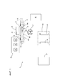
фигура 1 схематически показывает вид сверху установки для сборки шин в соответствии с настоящим изобретением;Figure 1 schematically shows a top view of a tire assembly apparatus in accordance with the present invention;
фигура 2 схематически показывает на виде сбоку и в частичном сечении загрузку каркасного рукава на станции формования;figure 2 schematically shows in side view and in partial section the loading of the frame sleeve at the molding station;
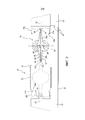
фигура 3 схематически показывает на виде сбоку и в частичном сечении зацепление каркасного рукава с формующими устройствами, размещенными на станции формования;figure 3 schematically shows in side view and in partial section the engagement of the frame sleeve with forming devices placed at the molding station;
фигура 3a показывает увеличенный вид детали, указанной с помощью «A» на фигуре 3;figure 3a shows an enlarged view of the part indicated by "A" in figure 3;
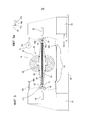
фигура 4 схематически показывает на виде сбоку и в частичном сечении выполнение формования каркасного рукава;figure 4 schematically shows in side view and in partial section the execution of the formation of the frame sleeve;
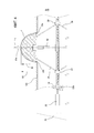
фигура 5 показывает наложение брекерного слоя на формованный каркасный рукав, соединенный с формующим барабаном;figure 5 shows the overlay of the belt layer on a molded frame sleeve connected to the forming drum;
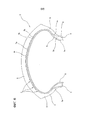
фигура 6 схематически показывает в радиальном полусечении шину, получаемую в соответствии с настоящим изобретением.figure 6 schematically shows in radial half-section the tire obtained in accordance with the present invention.
Со ссылкой на вышеупомянутые фигуры ссылочная позиция 1 указывает в целом установку для сборки шин для колес транспортных средств, выполненную с возможностью приведения в действие способа согласно настоящему изобретению.With reference to the aforementioned figures,
Установка 1 задумана для получения шин 2 (фигура 6), по существу содержащих по меньшей мере один каркасный слой 3, предпочтительно покрытый внутри слоем непроницаемого эластомерного материала или так называемым вкладышем 4. Две кольцевые анкерные конструкции 5, каждая из которых содержит так называемый сердечник 5a борта шины, предпочтительно поддерживающий эластомерный наполнитель 5b в радиально внешнем положении, зацеплены с соответственными концевыми клапанами 3a слоя/слоев 3 каркаса. Кольцевые анкерные конструкции 5 объединены вблизи областей, обычно называемых «борта» 6, в которых обычно происходит зацепление между шиной 2 и соответственным монтажным ободом (не проиллюстрирован).
Брекерная конструкция 7 по окружности накладывается вокруг слоя/слоев 3 каркаса, и протекторный браслет 8 по окружности накладывается на брекерную конструкцию 7. Две боковые стенки 9, каждая из которых продолжается от соответственного борта 6 к соответственному боковому краю протекторного браслета 8, накладываются в латерально противоположных положениях на слой/слои 3 каркаса.The
Установка 1 содержит линию 10 сборки каркаса, имеющую одну или более сборочных станций 11, где выполняется получение каркасного рукава 12, имеющего по существу цилиндрическую форму, например, согласно известным режимам. Каркасный рукав 12 содержит указанный по меньшей мере один каркасный слой 3, предпочтительно покрытой внутри вкладышем 4 и имеющий соответственные концевые клапаны 3a, зацепленные, например, путем загиба, с соответственными кольцевыми анкерными конструкциями 5. Если необходимо, каркасный рукав 12 также может содержать боковые стенки 9 или их первые участки, каждый из которых продолжается, начиная с соответственного борта 6.
Линия 10 сборки каркаса относится к станции 13 формования, содержащей устройства 14 для зацепления каркасного рукава 12 и формующие устройства 15, под действием которых каркасный рукав 12 принимает форму в соответствии с тороидальной конфигурацией.The
Устройства 14 зацепления, например, содержат первый фланцевый элемент 16а и второй фланцевый элемент 16b, коаксиально обращенные друг к другу и имеющие соответственные периферийные места 17а, 17b зацепления, посредством которых каждый из них является функционально зацепляемым на одной из кольцевых анкерных конструкций 5, соответственно поддерживаемых аксиально противоположными концами каркасного рукава 12.The
Устройства 14 зацепления также могут содержать элементы 18 для аксиального перемещения для фланцевых элементов 16а, 16b. Более подробно, может быть обеспечено то, что по меньшей мере один из фланцевых элементов 16а, 16b, например, первый фланцевый элемент 16а, поддерживается кареткой 19, подвижной вдоль одной или более линейных направляющих 20 параллельно геометрической оси X-X взаимного выравнивания между фланцевыми элементами 16а, 16b и предпочтительно выполненной за одно целое с неподвижным основанием 21, поддерживающим второй фланцевый элемент 16b. Перемещение каретки 19 вдоль линейной направляющей 20 определяет переключение станции 13 формования между состоянием загрузки/выгрузки и рабочим состоянием. В состоянии загрузки/выгрузки (фигура 2) первый фланцевый элемент 16а разнесен от второго фланцевого элемента 16b в соответствии с большим размером, который приблизительно по меньшей мере вдвое больше относительно аксиального размера неформованного каркасного рукава 12, приходящего с линии 10 сборки каркаса. В рабочем состоянии фланцевые элементы 16а, 16b, а, точнее говоря, их соответственные периферийные места 17а, 17b зацепления, взаимно разнесены в соответствии с размером, по существу соответствующим аксиальному размеру каркасного рукава 12.
Формующие устройства 15 могут, например, содержать гидрогазодинамическую схему (не показана) для введения воздуха под давлением или другой рабочей текучей среды накачивания между фланцевыми элементами 16а, 16b внутри каркасного рукава 12.Forming
Формующие устройства 15 также могут содержать один или более линейных приводов или других устройств 22 для аксиального перемещения, работающих на одном или предпочтительно обоих фланцевых элементах 16а, 16b, для того чтобы перемещать их аксиально по направлению друг к другу, начиная с вышеуказанного рабочего состояния. Взаимное сближение фланцевых элементов 16а, 16b вызывает взаимное сближение кольцевых анкерных конструкций 5 так, чтобы позволять формование каркасного рукава 12 в соответствии с тороидальной конфигурацией, сопровождаемое одновременным введением рабочей текучей среды под давлением в каркасный рукав 12.Forming
На станции 13 формования формуемый каркасный рукав 12 соединяется с тороидальным формующим барабаном 23 жестким и расширяемым, размещенным внутри самого каркасного рукава.At the forming
Формующий барабан 23 является расширяемым между первым рабочим состоянием, радиально сжатым (фигуры 2 и 3), и вторым радиально расширенным рабочим состоянием (фигуры 4 и 5). С этой целью может, например, быть обеспечено то, что формующий барабан 23 содержит множество секторов 24, распределенных по окружности вокруг центрального вала 25. Секторы 24 являются подвижными, предпочтительно одновременно друг с другом, из вышеуказанного первого рабочего состояния, в котором они находятся близко центральному валу 25, во второе рабочее состояние, в котором указанные секторы 24 перемещены в сторону от центрального вала 25. С этой целью может быть обеспечено то, что секторы 24 поддерживаются соответственными телескопическими выдвигаемыми направляющими элементами 26, радиально продолжающимися от центрального вала 25.The forming
Перемещение секторов 24 может быть достигнуто посредством механизмов 27 передачи, содержащих, например, рычаги 28 управления, которые шарнирно соединены, каждый на его соответственных противоположных концах, с одним из указанных секторов 24 и с по меньшей мере одной управляющей втулкой 29, установленной с возможностью скольжения вдоль центрального вала 25. Конкретнее, предпочтительно обеспечена пара управляющих втулок 29, расположенных вдоль центрального вала 25 в аксиально противоположных положениях относительно секторов 24, причем каждая зацепляет соответственные управляющие рычаги 28.The movement of the
Каждая управляющая втулка 29 функционально соединена с резьбовым стержнем 30, зацепляемым с возможностью вращения коаксиально внутри центрального вала 25. Резьбовой стержень 30 продолжается вдоль центрального вала 25 почти по всей его длине или за его пределами и несет на себе две аксиально противоположные резьбы 30a, 30b соответственно по часовой стрелке и против часовой стрелки. Функционально зацепляемыми на резьбах 30a, 30b являются соответственные гайки 31, аксиально подвижные внутри центрального вала 25, и причем каждая из которых соединена с одной из управляющих втулок 29, например, посредством по меньшей мере одного блока 32, радиально пересекающего центральный вал 25 по продольной щели 33.Each
Вращение резьбового стержня 30 в центральном валу 25, приводимое в действие посредством вращательного приводного устройства 34 или устройств привода другого типа, работающего на станции 13 формования, вызывает аксиальное перемещение гаек 31 и управляющих втулок 29, которому соответствует радиальное перемещение секторов 24 по направлению к первому или второму рабочему состоянию в соответствии с направлением вращения резьбового стержня 30.The rotation of the threaded
Во втором рабочем состоянии набор секторов 24 формующего барабана 23 образует вдоль его периферийного расширения радиально внешнюю тороидальную поверхность «S», не обязательно непрерывную, формуемую в соответствии с внутренней конфигурацией, которую часть каркасного рукава 12 должна принимать после завершения формования. Более подробно, предпочтительно может быть обеспечено то, что формующий барабан 23 во втором рабочем состоянии имеет коэффициент кривизны, составляющий от около 0,15 до около 0,45, обычно приспособленный для получения шин для мотоциклов или других двухколесных транспортных средств. Однако, если необходимо, для коэффициентов кривизны могут быть применены значения, которые ниже указанных выше, например, приспособленные для изготовления шин для автомобилей или грузовиков.In the second operating state, the set of
Предпочтительно, формующий барабан 23 размещают на станции 13 формования до того, как соответственный каркасный рукав 12, например, все еще обрабатываемый на линии 10 сборки каркаса, достигает саму станцию 13 формования.Preferably, the forming
Конкретнее, предпочтительно обеспечено то, что формующий барабан 23 поддерживается выступающим образом на станции 13 формования. Например, первый конец 25а центрального вала 25 формующего барабана 23 может с такой целью удерживаться оправкой 35, коаксиально размещенной в первом фланцевом элементе 16а и обеспеченной вращательным приводным устройством 34, соединяемым с резьбовым стержнем 30, для того чтобы приводить его во вращение.More specifically, it is preferably ensured that the forming
В связи с этим формующий барабан 23 может быть размещен в первом рабочем состоянии посредством указанного вращательного приводного устройства 34, если он еще не находится в таком состоянии при достижении станции 13 формования.In this regard, the forming
Посредством загрузочных устройств 36 каркаса каркасный рукав 12, приходящий с линии 10 сборки каркаса, далее передается на станцию 13 формования, для того чтобы быть коаксиально размещенным в радиально внешнем положении вокруг формующего барабана 23, размещенного в первом радиально сжатом рабочем состоянии.By means of the
Загрузочные устройства 36 каркаса могут, например, содержать погрузочно-разгрузочное устройство 37 каркаса, предпочтительно работающее на внешней поверхности каркасного рукава 12. С помощью радиального поступательного движения (относительно формующего барабана 23) каркасный рукав 12 сначала вставляется в отношении аксиального выравнивания с формующим барабаном 23 между фланцевыми элементами 16а, 16b, размещенными в состоянии загрузки/выгрузки (фигура 2). Каркасный рукав 12 в дальнейшем размещается вокруг формующего барабана 23 предпочтительно после аксиального поступательного движения самого формующего барабана. Конкретнее, с помощью перемещения каретки 19 вдоль линейных направляющих 20 формующий барабан 23 коаксиально вставляется в каркасный рукав 12. Предпочтительно, перемещение каретки 19 и формующего барабана 23 заканчивается зацеплением второго конца 25b центрального вала 25 с задней бабкой 38, расположенной внутри второго фланцевого элемента 16b (штриховая линия на фигуре 2).The
Для того чтобы аксиальное перемещение формующего барабана 23 относительно каркасного рукава 12 возникало без взаимных механических воздействий, предпочтительно обеспечено то, что в первом рабочем состоянии формующий барабан 23 имеет максимальный внешний диаметр, который меньше минимального внутреннего диаметра каркасного рукава 12, обычно обнаруживаемого у бортов 6.In order for the axial movement of the forming
В конце аксиального перемещения каждая из кольцевых анкерных конструкций 5, встроенных в борта 6, располагается в аксиально внутреннем положении относительно периферийных мест 17а, 17b зацепления соответственных первого и второго фланцевых элементов 16а, 16b.At the end of the axial movement, each of the
Под действием устройств 22 для аксиального перемещения фланцевые элементы 16а, 16b далее переносят соответственные места 17а, 17b зацепления по существу в отношении радиального выравнивания внутрь кольцевых анкерных конструкций 5.Under the action of the
Каждый из указанных фланцевых элементов 16а, 16b содержит элементы расширения (не изображены), выполненные с возможностью определения радиального расширения соответственных периферийных уплотнительных колец 39a, 39b, объединяющих в себе периферийные места 17а, 17b зацепления. После такого радиального расширения каждое из периферийных уплотнительных колец 39a, 39b подводится для воздействия в упорном отношении на одну из кольцевых анкерных конструкций 5. Таким образом, каркасный рукав 12 стабильно ограничивается фланцевыми элементами 16а, 16b. После завершения зацепления погрузочно-разгрузочное устройство 37 каркаса может отцепляться от каркасного рукава 12 и быть удалено от станции 13 формования.Each of these
Во время формования, когда каркасный рукав 12 начинает радиально расширяться, радиальное расширение формующего барабана может регулироваться посредством вращения резьбового стержня 30 под действием вращательного приводного устройства 34.During molding, when the
Формование каркасного рукава 12 выполняется без контакта между последним и формующим барабаном 23 по меньшей мере до того, как сам формующий барабан 23 не достигнет максимального радиального расширения при достижении его второго рабочего состояния.The forming of the
С этой целью может быть обеспечено использование устройств 40a, 40b отслеживания, которые циклически или непрерывно проверяют диаметральный размер, соответственно принимаемый каркасным рукавом 12 и формующим барабаном 23, для предотвращения их взаимных контактов во время этапа формования. В соответствии с такими действиями отслеживания, когда разница между внешним диаметром каркасного рукава 12 и внешним диаметром формующего барабана 23, например, в аксиальной плоскости «E» средней линии, перпендикулярной геометрической оси X-X и находящейся на одинаковом расстоянии от фланцевых элементов 16а, 16b и/или от кольцевых анкерных конструкций 5, падает ниже предварительно установленного порогового значения, устройства 40a, 40b отслеживания позволяют действия по управлению на вращательном приводном устройстве 34 и/или на формующих устройствах 15 так, что внешняя поверхность тороидального формующего барабана 23 остается разнесенной от каркасного рукава 12 во время расширения формующего барабана 23 по меньшей мере до того, как второе радиально расширенное рабочее состояние формующего барабана 23 не будет достигнуто.To this end,
Путем примера, устройства 40a, 40b отслеживания могут содержать по меньшей мере один первый оптический датчик 40a, размещенный снаружи каркасного рукава 12, для того чтобы обнаруживать его внешний диаметр вблизи аксиальной плоскости «E» средней линии, и по меньшей мере один преобразователь 40b, размещенный внутри одного из фланцевых элементов 16а, 16b и/или соединенный с вращательным приводным устройством 34, для того чтобы обнаруживать аксиальное положение, принимаемое по меньшей мере одной из управляющих втулок 29, и/или степень углового поворота, завершенного резьбовым стержнем 30, так, чтобы позволять электронному блоку обработки вычислять значение внешнего диаметра, принимаемого формующим барабаном 23.By way of example, the
При достижении заданного максимального значения диаметрального размера каркасного рукава 12 действие формующих устройств прерывается, и обеспечивается завершение радиального расширения формующего барабана 23, в результате чего он достигает второго рабочего состояния.Upon reaching the specified maximum value of the diametrical size of the
Далее обеспечивается соединение между каркасным рукавом 12 и формующим барабаном 23. Такое соединение подтверждается путем введения внутренней поверхности каркасного рукава 12 в контактное отношение с радиально внешней тороидальной поверхностью «S» формующего барабана 23.Further, a connection is provided between the
Предпочтительно обеспечивается то, что в конце формования внутренняя поверхность каркасного рукава 12 достигает максимального диаметра «D2», который больше максимального диаметра «D1», достигаемого внешней поверхностью формующего барабана 23 во втором рабочем состоянии. В связи с этим соединение может быть выполнено после незначительного радиального сжатия каркасного рукава 12, например, получаемого из-за упругого сжатия его же после откачивания рабочей текучей среды, предварительно введенной во время формования.Preferably, it is ensured that at the end of the molding, the inner surface of the
Для того чтобы облегчать расширение каркасного рукава 12 за пределы максимального диаметра, достигаемого формующим барабаном 23 во втором рабочем состоянии, может быть обеспечено то, что на заключительных этапах достижения состояния максимального радиального расширения каркасного рукава 12 фланцевые элементы 16а, 16b аксиально вставляются в радиально внутреннем положении относительно секторов 24 формующего барабана 23, который собирается достигнуть второго рабочего состояния.In order to facilitate the expansion of the
Достижение соединения посредством радиального сжатия каркасного рукава 12 облегчает равномерный контакт и при отсутствии трения между внутренней поверхностью каркасного рукава 12 и формующим барабаном 23 сохранение структурной целостности каркасного рукава 12, не вызывая изменения плотности распределения кордов, которые образуют слой или слои каркаса, и/или другие структурные искажения.Achieving the connection by radial compression of the
После завершения соединения фланцевые элементы 16а, 16b отцепляются от каркасного рукава 12, оставляя его на формующем барабане 23.After the connection is completed, the
Каркасный рукав 12 и формующий барабан 23 в отношении взаимного соединения приспособлены подвергаться действию по меньшей мере одного устройства 41 для сборки по меньшей мере одного брекерного слоя в радиально внешнем положении относительно формованного каркасного рукава 12. Такое устройство 41 предпочтительно установлено на станции 42 наложения брекерной конструкции, которая удалена относительно указанной станции 13 формования.The
Для того чтобы позволять передавать формующий барабан 23 на станцию 42 наложения брекерной конструкции, обеспечено то, что формующий барабан 23, поддерживающий каркасный рукав 12, поддерживается оправкой 35, работающей на первом конце 25а центрального вала 25, в то время как задняя бабка 38 отцепляется от второго конца 25b самого центрального вала 25. С отводом первого фланцевого элемента 16а станция 13 формования возвращается обратно в состояние загрузки/выгрузки, освобождая доступ к первой антропоморфной роботизированной руке 43 или другим подходящим устройствам передачи, которые, в свою очередь, зацепляют формующий барабан 23 на втором конце 25b центрального вала 25.In order to allow the transfer of the forming
Первая роботизированная рука 43 передает формующий барабан 23 от станции 13 формования к станции 42 наложения брекерной конструкции. Первая роботизированная рука 43 также соответственно перемещает формующий барабан 23 спереди устройства 41 для сборки брекерного слоя, которое может, например, содержать устройство выдачи, которое подает по меньшей мере один обрезиненный корд или другой непрерывный вытянутый усиливающий элемент, выполненный из текстильного или металлического материала. В связи с этим брекерный слой 7а получают путем намотки указанного непрерывного вытянутого усиливающего элемента в соответствии с аксиально смежными кольцевыми витками 44 вокруг радиально внешней поверхности «S» каркасного рукава 12, соединенного с расширенным тороидальным формующим барабаном 23, в то время как последний приводится во вращение и соответственно перемещается первой роботизированной рукой 43.The first
Жесткость формующего барабана 23 обеспечивает стабильное позиционирование отдельных кольцевых витков 44, образованных непосредственно на внешней поверхности формованного каркасного рукава 12, без нежелательных деформаций каркасного рукава 12, возникающих из-за напряжений, передаваемых на его внешнюю поверхность во время наложения. Адгезивность сырого эластомерного материала, который составляет слой или слои каркаса 3, предотвращает нежелательные спонтанные и/или неконтролируемые перемещения отдельных кольцевых витков 44 без необходимости размещать с этой целью дополнительные промежуточные слои между брекерным слоем 7а на этапе изготовления и нижележащей поверхностью наложения. Другими словами, облегчается точное позиционирование отдельных кольцевых витков 44 брекерного слоя 7а, непосредственно образуемого согласно желаемому окончательному профилю каркасного рукава 12 после завершения формования, даже когда такой профиль имеет выраженную поперечную кривизну, как, например, в шинах, предназначенных для мотоциклов или двухколесных транспортных средств.The stiffness of the forming
Станция 42 наложения брекерной конструкции может, если необходимо, содержать сборочные устройства 45 одного или более вспомогательных слоев 7b, накладываемых на формованный каркасный рукав 12 до или после наложения указанного по меньшей мере одного брекерного слоя 7а. В частности, такие вспомогательные слои 7b могут содержать текстильные или металлические параллельные корды, размещенные в соответствии с ориентацией, которая наклонена относительно направления периферийного расширения каркасного рукава 12, соответственно перекрещивающиеся между вспомогательными слоями 7b, смежными друг другу.The
Передача формующего барабана 23 между сборочными устройствами 45 вспомогательных слоев и сборочным устройством 41 брекерных слоев может быть назначена той же первой роботизированной руке 43 или второй антропоморфной роботизированной руке или погрузочно-разгрузочному устройству другого типа.The transfer of the forming
Формующий барабан 23 далее передается от станции 42 наложения брекерной конструкции к устройствам для получения протекторных браслетов 47, предпочтительно составляющим часть линии завершения сборки сырой шины, объединяющей в себе станцию 42 наложения брекерной конструкции.The forming
Устройства 47 для получения протекторных браслетов могут, например, содержать по меньшей мере один крутильный блок, выполненный с возможностью намотки по меньшей мере одного непрерывного вытянутого эластомерного элемента в соответствии с кольцевыми витками аксиально смежно во взаимном контакте в радиально внешнем положении вокруг брекерной конструкции 7, в то время как формующий барабан 23 приводится во вращение и соответственно перемещается для распределения кольцевых витков в соответствии с заданной схемой.Devices for producing
Наконец, установка 1 может содержать устройства получения боковых стенок (не показаны) на аксиально противоположных боковых участках каркасного рукава 12.Finally, the
Собранная сырая шина 2 приспособлена для удаления с формующего барабана 23 для того, чтобы подвергаться вулканизации в блоке 52 вулканизации.The assembled raw tire 2 is adapted to be removed from the forming
Claims (63)
Applications Claiming Priority (3)
| Application Number | Priority Date | Filing Date | Title |
|---|---|---|---|
| ITMI2013A001970 | 2013-11-26 | ||
| ITMI20131970 | 2013-11-26 | ||
| PCT/IB2014/065582 WO2015079344A1 (en) | 2013-11-26 | 2014-10-24 | Method and plant for building tyres |
Publications (2)
| Publication Number | Publication Date |
|---|---|
| RU2016124106A RU2016124106A (en) | 2018-01-09 |
| RU2678662C1 true RU2678662C1 (en) | 2019-01-30 |
Family
ID=50033620
Family Applications (1)
| Application Number | Title | Priority Date | Filing Date |
|---|---|---|---|
| RU2016124106A RU2678662C1 (en) | 2013-11-26 | 2014-10-24 | Method, process and plant for building tyres |
Country Status (9)
| Country | Link |
|---|---|
| US (3) | US10639860B2 (en) |
| EP (1) | EP3074216B1 (en) |
| JP (1) | JP6546168B2 (en) |
| KR (1) | KR102249240B1 (en) |
| CN (1) | CN105813832B (en) |
| BR (1) | BR112016011153B1 (en) |
| MX (1) | MX2016006407A (en) |
| RU (1) | RU2678662C1 (en) |
| WO (1) | WO2015079344A1 (en) |
Families Citing this family (6)
| Publication number | Priority date | Publication date | Assignee | Title |
|---|---|---|---|---|
| BR112016011153B1 (en) | 2013-11-26 | 2021-10-13 | Pirelli Tyre S.P.A | PROCESS AND INSTALLATION TO BUILD TIRES |
| CN108698347B (en) * | 2015-12-28 | 2021-01-01 | 倍耐力轮胎股份公司 | Process and plant for building tyres |
| BR112019011505B1 (en) | 2016-12-16 | 2023-03-28 | Pirelli Tyre S.P.A | PROCESS AND PLANT TO BUILD TIRES |
| US20190070813A1 (en) * | 2017-09-01 | 2019-03-07 | The Goodyear Tire & Rubber Company | Tire building drum |
| FR3090468A3 (en) * | 2018-12-20 | 2020-06-26 | Michelin & Cie | Drum and method of manufacturing a tire blank |
| IT201900024694A1 (en) * | 2019-12-19 | 2021-06-19 | Pirelli | Process and plant for the production of tires for vehicle wheels |
Citations (5)
| Publication number | Priority date | Publication date | Assignee | Title |
|---|---|---|---|---|
| US3674604A (en) * | 1966-02-25 | 1972-07-04 | Nrm Corp | Tire building drum |
| JPS57212046A (en) * | 1981-06-24 | 1982-12-27 | Yokohama Rubber Co Ltd:The | Second stage green tire molding drum |
| US6234227B1 (en) * | 1996-06-11 | 2001-05-22 | Compagnie Generale Des Etablissements Michelin - Michelin & Cie | Tire assembly drum |
| EP1547757A1 (en) * | 2002-08-05 | 2005-06-29 | Bridgestone Corporation | Tire molding drum and tire molding method |
| RU2455165C2 (en) * | 2007-02-15 | 2012-07-10 | Пирелли Тайр С.П.А. | Method and device for assembling tires |
Family Cites Families (48)
| Publication number | Priority date | Publication date | Assignee | Title |
|---|---|---|---|---|
| US3776802A (en) | 1971-08-23 | 1973-12-04 | Nat Standard Co | Tire building apparatus |
| US3867230A (en) * | 1973-02-08 | 1975-02-18 | Goodrich Co B F | Tire building machine |
| US3822165A (en) | 1973-02-16 | 1974-07-02 | Uniroyal Inc | Shaping drum |
| US3776230A (en) | 1973-04-18 | 1973-12-04 | C Neefe | Method of rapidly reshaping the cornea to eliminate refractive errors |
| GB1487426A (en) | 1974-09-17 | 1977-09-28 | Bekaert Sa Nv | Reinforcement of vehicle tyres |
| US4271487A (en) | 1979-11-13 | 1981-06-02 | Ncr Corporation | Static volatile/non-volatile ram cell |
| FR2492841B1 (en) | 1980-10-23 | 1983-07-22 | Agronomique Inst Nat Rech | MUTANT VIRUS OF VIRAL HEMORRHAGIC SEPTICEMIA, VACCINE CONTAINING THIS MUTANT, AND PROCESS FOR PREPARING THE SAME |
| US4769104A (en) | 1986-11-11 | 1988-09-06 | Bridgestone Corporation | Apparatus for sticking a tire component member |
| JP3187954B2 (en) | 1992-07-21 | 2001-07-16 | 三菱重工業株式会社 | Tire building system |
| DE69410851D1 (en) | 1993-03-04 | 1998-07-16 | Bridgestone Corp | Process for building green tires |
| US5635016A (en) | 1995-10-24 | 1997-06-03 | Wyko, Inc. | Transfer ring or drum apparatus with adjustable circumference |
| DE19742035C1 (en) * | 1997-09-24 | 1999-04-08 | Continental Ag | Method and drum as a device for building a green tire |
| US6012500A (en) | 1998-01-23 | 2000-01-11 | Bridgestone/Firestone, Inc. | Second stage tire building machine utilizing bladderless former sleeve |
| JP3474446B2 (en) * | 1998-06-05 | 2003-12-08 | ローレルバンクマシン株式会社 | Change making device |
| JP2002059707A (en) * | 2000-08-23 | 2002-02-26 | Bridgestone Corp | Pneumatic tire and manufacturing method for pneumatic tire |
| US6797095B2 (en) | 2000-11-29 | 2004-09-28 | Pirelli Pneumatici S.P.A. | Method and plant for manufacturing a belt structure, a belt package and a crown structure of a green tire |
| US7126151B2 (en) * | 2001-05-21 | 2006-10-24 | The Regents Of The University Of Colorado, A Body Corporate | Interconnected high speed electron tunneling devices |
| AU2003251082A1 (en) | 2002-11-05 | 2004-06-07 | Pirelli Pneumatici S.P.A. | Process and plant for manufacturing tires for vehicle wheels |
| JP4166081B2 (en) | 2002-12-25 | 2008-10-15 | 株式会社ブリヂストン | Method and apparatus for manufacturing tire intermediate member |
| US7195047B2 (en) * | 2003-12-11 | 2007-03-27 | The Goodyear Tire And Rubber Company | Tire manufacturing module and method of manufacturing tires |
| JP4226495B2 (en) * | 2004-03-05 | 2009-02-18 | 株式会社ブリヂストン | Tire molding drum and molding system, process design method, and manufacturing method of tire molded thereby |
| JP4383218B2 (en) * | 2004-03-29 | 2009-12-16 | 株式会社ブリヂストン | Method and apparatus for turning driving of trolley and tire molding system using the same |
| US8055745B2 (en) * | 2004-06-01 | 2011-11-08 | Inmage Systems, Inc. | Methods and apparatus for accessing data from a primary data storage system for secondary storage |
| US20060014449A1 (en) * | 2004-07-15 | 2006-01-19 | David French | Body surfboard |
| DE102004058522A1 (en) | 2004-12-04 | 2006-06-14 | Continental Aktiengesellschaft | Method and device for constructing a radial tire |
| JP4585307B2 (en) * | 2004-12-24 | 2010-11-24 | 住友ゴム工業株式会社 | Method for manufacturing motorcycle tire |
| EP1870257B1 (en) | 2005-04-15 | 2012-03-07 | Bridgestone Corporation | Pneumatic tire for motorcycle and method of manufacturing the same |
| DE102007031758A1 (en) | 2007-07-07 | 2009-01-08 | Continental Aktiengesellschaft | Method for constructing a radial tire |
| WO2009157028A1 (en) * | 2008-06-27 | 2009-12-30 | Pirelli Tyre S.P.A. | Process and plant for building tyres for vehicle wheels |
| JP2012513334A (en) * | 2008-12-22 | 2012-06-14 | ピレリ・タイヤ・ソチエタ・ペル・アツィオーニ | Two-wheeled vehicle tire and manufacturing method thereof |
| JP4816761B2 (en) * | 2009-05-07 | 2011-11-16 | 横浜ゴム株式会社 | Pneumatic tire manufacturing method |
| JP2010269543A (en) * | 2009-05-22 | 2010-12-02 | Sumitomo Rubber Ind Ltd | Manufacturing method for pneumatic tire |
| CN102427933B (en) | 2009-06-01 | 2016-05-11 | 株式会社普利司通 | Tyre producing drum, not tire curing manufacturing installation and manufacture method |
| JP5414415B2 (en) * | 2009-08-06 | 2014-02-12 | 株式会社日立製作所 | Semiconductor light receiving element and manufacturing method thereof |
| WO2011125944A1 (en) * | 2010-04-05 | 2011-10-13 | 三菱電機株式会社 | Leakage current reducing device |
| JP5551513B2 (en) | 2010-05-21 | 2014-07-16 | 株式会社ブリヂストン | Raw tire molding method |
| CN102152265B (en) * | 2011-02-22 | 2014-08-06 | 大行科技(深圳)有限公司 | Wrench tool |
| ITMI20110721A1 (en) | 2011-04-29 | 2012-10-30 | Pirelli | PROCESS AND EQUIPMENT FOR PACKING TIRES FOR VEHICLE WHEELS |
| US9102113B2 (en) * | 2011-10-31 | 2015-08-11 | Bridgestone Americas Tire Operations, Llc | Band drum pop-up hinge |
| CN103171167A (en) | 2011-12-22 | 2013-06-26 | 软控股份有限公司 | Tire bead transfer ring and transferring method of tire bead transfer ring |
| DE102012112495A1 (en) | 2012-12-18 | 2014-06-18 | Continental Reifen Deutschland Gmbh | Method for producing a vehicle tire |
| JP5723412B2 (en) * | 2013-05-20 | 2015-05-27 | 住友ゴム工業株式会社 | Method for manufacturing motorcycle tire |
| CN105451978B (en) | 2013-08-01 | 2019-02-12 | 倍耐力轮胎股份公司 | For being configured to the processing and equipment and for the tire of wheel of vehicle of the tire of wheel of vehicle |
| BR112016011153B1 (en) | 2013-11-26 | 2021-10-13 | Pirelli Tyre S.P.A | PROCESS AND INSTALLATION TO BUILD TIRES |
| US20150239190A1 (en) | 2014-02-27 | 2015-08-27 | The Goodyear Tire & Rubber Company | Transfer ring or drum apparatus with adjustable circumference |
| JP6200360B2 (en) | 2014-03-25 | 2017-09-20 | 住友ゴム工業株式会社 | Method for manufacturing motorcycle tire |
| RU2717781C2 (en) | 2014-11-14 | 2020-03-25 | Пирелли Тайр С.П.А. | Method and plant for tires assembly |
| CN108698347B (en) | 2015-12-28 | 2021-01-01 | 倍耐力轮胎股份公司 | Process and plant for building tyres |
-
2014
- 2014-10-24 BR BR112016011153-2A patent/BR112016011153B1/en active IP Right Grant
- 2014-10-24 US US15/037,209 patent/US10639860B2/en active Active
- 2014-10-24 RU RU2016124106A patent/RU2678662C1/en active
- 2014-10-24 WO PCT/IB2014/065582 patent/WO2015079344A1/en active Application Filing
- 2014-10-24 MX MX2016006407A patent/MX2016006407A/en active IP Right Grant
- 2014-10-24 CN CN201480064340.9A patent/CN105813832B/en active Active
- 2014-10-24 JP JP2016530960A patent/JP6546168B2/en active Active
- 2014-10-24 EP EP14800142.3A patent/EP3074216B1/en active Active
- 2014-10-24 KR KR1020167015480A patent/KR102249240B1/en active IP Right Grant
-
2020
- 2020-03-31 US US16/836,545 patent/US11230075B2/en active Active
-
2021
- 2021-12-13 US US17/549,380 patent/US11701851B2/en active Active
Patent Citations (5)
| Publication number | Priority date | Publication date | Assignee | Title |
|---|---|---|---|---|
| US3674604A (en) * | 1966-02-25 | 1972-07-04 | Nrm Corp | Tire building drum |
| JPS57212046A (en) * | 1981-06-24 | 1982-12-27 | Yokohama Rubber Co Ltd:The | Second stage green tire molding drum |
| US6234227B1 (en) * | 1996-06-11 | 2001-05-22 | Compagnie Generale Des Etablissements Michelin - Michelin & Cie | Tire assembly drum |
| EP1547757A1 (en) * | 2002-08-05 | 2005-06-29 | Bridgestone Corporation | Tire molding drum and tire molding method |
| RU2455165C2 (en) * | 2007-02-15 | 2012-07-10 | Пирелли Тайр С.П.А. | Method and device for assembling tires |
Also Published As
| Publication number | Publication date |
|---|---|
| BR112016011153B1 (en) | 2021-10-13 |
| CN105813832B (en) | 2018-06-15 |
| US20220105698A1 (en) | 2022-04-07 |
| US11230075B2 (en) | 2022-01-25 |
| EP3074216B1 (en) | 2019-05-15 |
| US20160297158A1 (en) | 2016-10-13 |
| RU2016124106A (en) | 2018-01-09 |
| US11701851B2 (en) | 2023-07-18 |
| US20200247075A1 (en) | 2020-08-06 |
| JP6546168B2 (en) | 2019-07-17 |
| US10639860B2 (en) | 2020-05-05 |
| KR20160090316A (en) | 2016-07-29 |
| CN105813832A (en) | 2016-07-27 |
| JP2016537224A (en) | 2016-12-01 |
| KR102249240B1 (en) | 2021-05-07 |
| WO2015079344A1 (en) | 2015-06-04 |
| BR112016011153A2 (en) | 2017-08-08 |
| MX2016006407A (en) | 2016-10-28 |
| EP3074216A1 (en) | 2016-10-05 |
Similar Documents
| Publication | Publication Date | Title |
|---|---|---|
| RU2678662C1 (en) | Method, process and plant for building tyres | |
| CN100522579C (en) | Method and apparatus of forming annular elastic tyre parts | |
| US10759132B2 (en) | Process and plant for building tyres | |
| US20160067935A1 (en) | Process and apparatus for manufacturing tyres | |
| KR102416186B1 (en) | Inflatable forming drum and manufacturing method for manufacturing tire for vehicle wheel | |
| CN110072691A (en) | For constructing the technique and equipment that are used for the tire of wheel of vehicle | |
| JP5261499B2 (en) | Method and plant for building tires for vehicle wheels | |
| CN108025518B (en) | Process and plant for building tyres | |
| CN108698347B (en) | Process and plant for building tyres | |
| US9789657B2 (en) | Process for building tyres and tyre obtainable by said process | |
| CN106457713B (en) | Process and plant for building tyres | |
| EP2934869B1 (en) | A method for controlling the geometry of green tyres different from each other and a process for manufacturing tyres different form each other | |
| CN102463682B (en) | Segmented tire building core and method of making a tire |