EP2430900A1 - Vorsatzgerät - Google Patents
Vorsatzgerät Download PDFInfo
- Publication number
- EP2430900A1 EP2430900A1 EP11173385A EP11173385A EP2430900A1 EP 2430900 A1 EP2430900 A1 EP 2430900A1 EP 11173385 A EP11173385 A EP 11173385A EP 11173385 A EP11173385 A EP 11173385A EP 2430900 A1 EP2430900 A1 EP 2430900A1
- Authority
- EP
- European Patent Office
- Prior art keywords
- attachment
- cutting
- cutting device
- crop
- hard material
- Prior art date
- Legal status (The legal status is an assumption and is not a legal conclusion. Google has not performed a legal analysis and makes no representation as to the accuracy of the status listed.)
- Granted
Links
Images




Classifications
-
- A—HUMAN NECESSITIES
- A01—AGRICULTURE; FORESTRY; ANIMAL HUSBANDRY; HUNTING; TRAPPING; FISHING
- A01D—HARVESTING; MOWING
- A01D34/00—Mowers; Mowing apparatus of harvesters
- A01D34/01—Mowers; Mowing apparatus of harvesters characterised by features relating to the type of cutting apparatus
- A01D34/83—Mowers; Mowing apparatus of harvesters characterised by features relating to the type of cutting apparatus having cutting members on endless belts or sprocket chains
-
- A—HUMAN NECESSITIES
- A01—AGRICULTURE; FORESTRY; ANIMAL HUSBANDRY; HUNTING; TRAPPING; FISHING
- A01D—HARVESTING; MOWING
- A01D34/00—Mowers; Mowing apparatus of harvesters
- A01D34/835—Mowers; Mowing apparatus of harvesters specially adapted for particular purposes
- A01D34/8355—Mowers; Mowing apparatus of harvesters specially adapted for particular purposes for cutting up or crushing remaining standing stalks, e.g. stubble
Definitions
- the present invention relates to an attachment for harvesting stalk-like crop for a self-propelled harvesting machine according to the preamble of claim 1.
- the generic EP 1 629 707 A1 describes a header for a self-propelled harvester with a cutting device for separating stalk-like crop and a feeder designed as auger conveyor for removal of the separated crop to a collection device of the harvester.
- the cutting device has two mower bar sections driven via a mower blade drive train in each case, which are driven in an oscillating manner by the mower blade drive train.
- the oscillating drive of the cutter bar sections leads to the occurrence of large lateral acceleration forces due to the inertia of the cutter bar sections in the points of the direction of movement reversal.
- Object of the present invention is therefore to develop a header of the type mentioned in such a way that the occurrence of transverse acceleration is avoided at the at least one cutting device.
- the at least one cutting device is designed as at least one endlessly circulating, a cylindrical cross-section exhibiting support member having at least one cutting element with a hardstoff emotions pasn coating, wherein the attachment comprises at least one pair of deflection elements that the drive and the Guiding the serve at least one cutting device.
- the endlessly circulating Cutting device requires no reversing drive, so that the occurrence of lateral acceleration forces in the reversal points due to the inertia of the cutting device is avoided.
- such a cutting device of an attachment is characterized by a lower weight, as known from the prior art Mähbalkenabitese.
- Another advantage resulting from the reduced weight and elimination of the direction of travel reversal is that the attachment can be moved across the field by the self-propelled harvester at a higher speed because the cutter is operable at higher speeds.
- the cutting element can be made hollow cylindrical and arranged concentrically to the longitudinal axis of the carrier element at this.
- a configured cutting device allows the separation of stalk-like crop without the need for a defined cutting plane, as is the case with blade-shaped cutting elements.
- a further advantage results from the weight reduction of the cutting device, because the preferably sleeve-shaped cutting elements are mounted directly on the cylindrical support having a cylindrical cross-section, which is designed in particular as a rope made of a high-strength plastic or metal, so that elaborate fasteners for Attachment of the cutting elements, as required in the prior art, can be dispensed with.
- the hollow cylindrical cutting element has a shape corresponding to the cylindrical cross section of the carrier element.
- the cutting element can be designed as a fastening element with a cutting tooth provided thereon and provided with a coating containing hard material.
- the fastening element carries the cutting tooth and serves to support and guide it in a plane parallel to the direction of rotation of the carrier element.
- the fastening element has a hollow cylindrical portion which allows a concentric arrangement on the carrier element.
- the fastening element can at least partially engage with the deflection elements form-fitting manner.
- a guidance of the respective cutting tooth is achieved in a defined plane.
- the cutting tooth is additionally held in the region between the deflecting elements in a defined plane in order to allow the uniform separation of the crop.
- the hard-body-containing coating may be embodied as a hard metal layer, which may contain diamond grains and / or ceramic particles.
- the at least one pair of deflection elements can be arranged on the underside of the attachment facing the floor.
- the at least one cutting device lying in a substantially horizontal plane, upstream of the conveyor be arranged on the attachment.
- This arrangement of the cutting device on the attachment is the classical positioning of the cutting device instead of a conventional cutter bar section on a cutting unit.
- the cutting device can be arranged rotatable about a horizontal axis on the bottom of the attachment facing the ground.
- This arrangement allows the use of attachments, for example, intended specifically for the corn or sunflower harvest, so-called corn pickers.
- a cutter arranged in such a manner on a header provided for the maize or sunflower harvest serves to replace the conventional underfloor chopper.
- a second cutting device can furthermore be arranged on the attachment device in a position inclined at an angle to the cutting plane of the first cutting device and located downstream of the conveying device.
- the second cutting device is used for high crop cutting.
- the second cutting device may have a plurality of mutually parallel planes over which an endlessly circulating support element can be guided and driven by a plurality of deflection elements arranged in pairs in a plane.
- FIG. 1 shows a side view of a cutting unit 1 for a self-propelled harvester, in particular a combine harvester, which is detachably mounted on a feeder of the combine.
- the cutting unit 1 has a cutting table 2 with a cutting trough, which is provided at both ends with a respective side wall. Between the side walls there is a rear wall 3 arranged vertically to the cutting unit recess. Above the cutting unit recess, at least one conveying device 4 is arranged approximately flush between the side walls and is designed as a feed screw 7 driven in rotation. The conveyor 4 promotes separated stalk-like crop 6 in the direction of the intake channel of the combine.
- the stem-like crop 6 is separated from at least one arranged below the cutting table 2, substantially parallel to the longitudinal axis of the cutting table 2 extending cutting device 5.
- a rotationally driven, height-adjustable known per se and therefore not shown reel is arranged in front of the feed screw designed as a feed screw 4, with which the crop is deflected via the cutting device 5 in the direction of the cutting trough.
- the cutting device 5 is embodied as at least one endlessly revolving carrier element 8 having a cylindrical cross section, which according to FIG. 14 has at least one cutting element 11 with a coating 12 containing hard material.
- the drive and the guide of the cutting device 5 is effected by at least one pair of deflection elements 9, which are also arranged lying below the cutting table 2 on the cutting unit 1 in a horizontal plane.
- the drive of the cutting device 5 can be hydraulically, electrically or mechanically, preferably in the form of a belt drive.
- the endlessly circulating carrier element 8 is designed as a cable, preferably as a wire rope, which is equipped with a plurality of hollow cylindrical, preferably an annular cross-section having cutting elements 11 which are arranged concentrically to the longitudinal axis of the support member 8 on this with a slight distance in a row.
- the sleeve-shaped cutting elements 11 have a hard material body-containing coating 12, which contains diamond grains or ceramic particles and is designed as a hard metal layer.
- the running as a wire rope carrier element 8 with the cutting elements 11 disposed thereon is positively in a corresponding with the cross section of the cutting elements 11 recess 10 of the deflecting element 9 at.
- FIG. 2 shows a side view of a second embodiment of the cutting mechanism 1 according to Fig. 1 ,
- a second cutting device 14 is arranged on the cutting unit 1, which can be used in the high-cut process.
- the second cutting device 14 is pivoted on the rear wall 3 of the cutting unit 1 about a horizontal pivot axis 15, so that the second cutting device 14 is guided inclined at an angle to the cutting plane of the first cutting device 5.
- the second cutting device 14 differs from the first cutting device 5 in that the continuous carrier element 8 embodied as a wire rope is guided over a plurality of deflecting elements 9 arranged in a plurality of horizontal planes as viewed in the vertical direction Fig. 3 is illustrated in more detail, and which are arranged in a frame 13.
- the first cutting device 5 separates the crop just below the fruit stalls, so that longer stubble remain on the field. These longer stubbles are formed by the second cutting device 14 arranged downstream of the first cutting device 5 in the direction of movement of the cutting mechanism 1 and having a plurality of cutting planes extending in the vertical direction, as in FIG Fig. 3 is shown, separated.
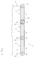
- FIG. 3 shows a schematic detail view of the second cutting device 14 in a plan view in the direction of arrow A.
- the endless support member 8 is seen in the vertical direction at a transition from one level to the next higher level looped around the deflecting elements 9, whereby in each plane with respect to the previous level Direction reversal of the endless circulating support member 8 of the second cutting device 14 is achieved, as illustrated by the directional arrows R.
- Fig. 4 is a second embodiment of a running as a cutting unit 1 attachment according to Fig. 1 shown.
- several cutting devices 5 arranged side by side over the width of the cutting unit 1 extending.
- the cutting unit 1 In order to maintain the tension of the support elements 8 of the cutting devices 5, the cutting unit 1 on a outside a stationary deflection element 17, which serves as a drive and guide means of the cutting devices 5 and, relative to the cutting table 2, fixedly arranged on a rotation axis 19 is.
- further deflecting elements 16, 16 ', 16 are arranged at a distance from one another, which are displaceable parallel to and relative to the cutting table 2 about a vertical axis 18.
- a first carrier element 8 surrounds the stationary deflecting element 17 and the first pivotable deflecting element 16.
- the number of movable deflecting elements 16, 16 ', 16 dependss on the total width of the cutting work 1.
- the displaceable deflecting elements 16, 16', 16" has the task of clamping the endlessly circulating support elements 8, 8 ', 8 ", in order to guide the respective carrier element 8, 8 ', 8 "in the longitudinal direction of the cutting mechanism 1 one behind the other and to drive.
- the carrier element 8 is arranged offset relative to the following carrier element 8 'in the vertical direction, in order to avoid overlapping of the carrier elements 8, 8' or 8 ', 8 ", thus transmitting the first carrier element 8 to the rotational speed of the driven stationary deflecting element 17 The next displaceable deflecting element 16.
- Fig. 5 provides a detailed view of a second embodiment of a cutting element 21 according to Fig. 1A
- the cutting element 21, which is shown in detail and is arranged concentrically to the longitudinal axis of the carrier element 8, comprises a hollow-cylindrical fastening element 22 with which the cutting element 21 can be fastened to the carrier element 8.
- the cutting element 21 comprises an at least partially provided with a hard material body-containing coating 12 cutting tooth 23.
- the cutting tooth 23 has a in the longitudinal direction of the support member 8 extending, substantially triangular contour. At least one outer edge forming the cutting edge and rising from the fastening element 22 is provided with a coating 12 containing hard material.
- the fastening element 22 is executed on its the deflecting element 9 facing side frusto-conical.
- the frusto-conical fastening element 22 is held in a form-locking manner in a substantially V-shaped recess 24 of the deflection element 9 which corresponds to the shape of the fastening element 22 and is guided by the latter.
- the fastening element 22 and the recess 24 of the deflecting element 9 consist in their mutually facing guide surfaces of a pair of materials, such as a plastic on the one hand and a metal on the other.
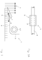
- the representation in Fig. 6 shows a schematic view of another embodiment of the cutting device 5 as an underfloor chopping device of a so-called known so-called maize picker, not shown.
- the cutting device 5 has at least one endlessly circulating carrier element 8, which has a cylindrical cross-section, and which has at least one cutting element 11 according to FIG Fig. 1A comprising a hard material body-containing coating, wherein the cutting device 5 is arranged pivotable about a horizontal axis on the underside of the corn picker.
- the end receives a respective bearing shaft 25 to which the holding device 32 is pivotally mounted on the corn picker.
- a substantially C-shaped frame member 26 connects, in which the deflecting element 9 is rotatably mounted about a vertical axis 27.
- the frame members 26 are interconnected by a strut 28.
- the respective frame element 26 is designed to be open on its opposite sides, so that the deflecting element 9 and the carrier element 8 can rotate freely about the strut 28.
- the vertical axis 27 is provided with a hydraulic motor 29 which is fed from a provided on the self-propelled harvester hydraulic circuit.
- the hydraulic oil is supplied to the hydraulic motor 29 through a rotary leadthrough 30 in the respective bearing shaft 25 and a hydraulic line 31 in the frame member 26.
- the hydraulic oil continues to flow from the hydraulic motor 29 back to the hydraulic circuit of the self-propelled harvester via a hydraulic line 31 provided in the strut 28 and the subsequent further C-shaped frame element 26.
Landscapes
- Life Sciences & Earth Sciences (AREA)
- Environmental Sciences (AREA)
- Harvesting Machines For Specific Crops (AREA)
- Harvester Elements (AREA)
- Outside Dividers And Delivering Mechanisms For Harvesters (AREA)
Abstract
Description
- Die vorliegende Erfindung betrifft ein Vorsatzgerät zum Ernten von stängelartigem Erntegut für eine selbstfahrende Erntemaschine gemäß dem Oberbegriff des Anspruches 1.
- Die gattungsbildende
EP 1 629 707 A1 beschreibt ein Vorsatzgerät für eine selbstfahrenden Erntemaschine mit einer Schneidvorrichtung zum Abtrennen von stängelartigem Erntegut sowie einer als Einzugsschnecke ausgebildeten Fördereinrichtung zur Abförderung des abgetrennten Erntegutes zu einer Einzugsvorrichtung der Erntemaschine. Die Schneidvorrichtung weist zwei über jeweils einen Mähmesserantriebsstrang angetriebene Mähbalkenabschnitte auf, die von dem Mähmesserantriebsstrang oszillierend angetrieben werden. Der oszillierende Antrieb der Mähbalkenabschnitte führt in den Punkten der Bewegungsrichtungsumkehr zum Auftreten großer Querbeschleunigungskräfte auf Grund der Massenträgheit der Mähbalkenabschnitte. - Aufgabe der vorliegenden Erfindung ist es daher, ein Vorsatzgerät der eingangs genannten Art derart weiterzubilden, dass das Auftreten von Querbeschleunigungen an der mindestens einen Schneidvorrichtung vermieden wird.
- Diese Aufgabe wird erfindungsgemäß durch die kennzeichnenden Merkmale des Anspruches 1 gelöst.
- Vorteilhafte Weiterbildungen der Erfindung sind Gegenstand der Unteransprüche.
- Gemäß dem Anspruch 1 wird vorgeschlagen, dass die mindestens eine Schneidvorrichtung als zumindest ein endlos umlaufendes, einen zylindrischen Querschnitt aufweisendes Trägerelement ausgeführt ist, welches mindestens ein Schneidelement mit einer hartstoffkörperhaltigen Beschichtung aufweist, wobei das Vorsatzgerät zumindest ein Paar Umlenkelemente umfasst, die dem Antrieb und der Führung der mindestens einen Schneidvorrichtung dienen. Die endlos umlaufende Schneidvorrichtung bedarf keines reversierenden Antriebes, so dass das Auftreten von Querbeschleunigungskräften in den Umkehrpunkten auf Grund der Massenträgheit der Schneidvorrichtung vermieden wird. Darüber hinaus zeichnet sich eine derartige Schneidvorrichtung eines Vorsatzgerätes durch ein geringeres Gewicht aus, als die aus dem Stand der Technik bekannten Mähbalkenabschnitte. Ein weiterer Vorteil, der sich aus dem geringeren Gewicht und dem Wegfall der Bewegungsrichtungsumkehr ergibt, besteht darin, dass das Vorsatzgerät von der selbstfahrenden Erntemaschine mit einer höhere Geschwindigkeit über ein Feld bewegt werden kann, da die Schneidvorrichtung mit höheren Geschwindigkeiten betreibbar ist.
- Vorzugsweise kann das Schneidelement hohlzylindrisch ausgeführt und konzentrisch zur Längsachse des Trägerelementes an diesem angeordnet sein. Eine derart ausgestaltete Schneidvorrichtung ermöglicht das Abtrennen von stängelartigem Erntegut ohne dass es einer definierten Schnittebene bedarf, wie es bei klingenförmigen Schneidelementen der Fall ist. Ein weiterer Vorteil ergibt sich aus der Gewichtsreduzierung der Schneidvorrichtung, weil die vorzugsweise hülsenförmigen Schneidelemente unmittelbar auf dem einen zylindrischen Querschnitt aufweisenden Trägerelement, welches insbesondere als ein Seil aus einem hochfesten Kunststoff oder aus Metall ausgeführt ist, angebracht sind, so dass auf aufwändige Befestigungselemente für die Anbringung der Schneidelemente, wie es im Stand der Technik erforderlich ist, verzichtet werden kann. Vorzugsweise weist das hohlzylindrische Schneidelement eine mit dem zylindrischen Querschnitt des Trägerelementes korrespondierende Form auf.
- Gemäß einer alternativen Weiterbildung kann das Schneidelement als ein Befestigungselement mit einem daran angeordneten, mit einer hartstoffkörperhaltigen Beschichtung versehenen Schneidzahn ausgeführt sein. Das Befestigungselement trägt den Schneidzahn und dient dessen Halterung und Führung in einer zu der Umlaufrichtung des Trägerelementes parallelen Ebene. Für die Befestigung des Schneidelementes an dem Trägerelement weist das Befestigungselement einen hohlzylindrischen Abschnitt auf, der eine konzentrische Anordnung an dem Trägerelement ermöglicht.
- Um die Führung des Schneidelementes mit Schneidzahn zu erreichen, kann das Befestigungselement zumindest abschnittsweise mit den Umlenkelementen formschlüssig in Eingriff stehen. Durch den zumindest abschnittsweise formschlüssigen Eingriff des Befestigungselementes mit den Umlenkelementen wird eine Führung des jeweiligen Schneidzahnes in einer definierten Ebene erreicht. In bevorzugter Weiterbildung kann mindestens eine Führungsleiste zwischen den Umlenkelementen und parallel zu dem Trägerelement an der dem abzutrennenden Erntegut zugewandten Seite des Vorsatzgerätes angeordnet, mit welcher das Befestigungselement formschlüssig in Eingriff stehen kann. Auf diese Weise wird der Schneidzahn in dem Bereich zwischen den Umlenkelementen zusätzlich in einer definierten Ebene gehalten, um das gleichmäßige Abtrennen des Erntegutes zu ermöglichen.
- Insbesondere kann die hartkörperhaltige Beschichtung als eine Hartmetallschicht ausgeführt sein, die Diamantkörner und/ oder Keramikpartikel enthalten kann.
- Vorzugsweise kann das zumindest eine Paar Umlenkelemente auf der dem Boden zugewandten Unterseite des Vorsatzgerätes angeordnet sein.
- Dabei kann die mindestens eine Schneidvorrichtung in einer im Wesentlichen horizontalen Ebene liegend, der Fördereinrichtung vorgelagert, an dem Vorsatzgerät angeordnet sein. Bei dieser Anordnung der Schneidvorrichtung am Vorsatzgerät handelt es sich um die klassische Positionierung der Schneidvorrichtung anstelle eines konventionellen Mähbalkenabschnittes an einem Schneidwerk.
- In einer bevorzugten Weiterbildung des Vorsatzgerätes kann die Schneidvorrichtung um eine horizontale Achse rotierbar auf der dem Boden zugewandten Unterseite des Vorsatzgerätes angeordnet sein. Diese Anordnung ermöglicht den Einsatz an Vorsatzgeräten, die beispielsweise speziell für die Mais- oder Sonnenblumenernte vorgesehen sind, so genannten Maispflückern. Eine derart an einem für die Mais- oder Sonnenblumenernte vorgesehenen Vorsatzgerät angeordnete Schneidvorrichtung dient dazu, den konventionellen Unterflurhäcksler zu ersetzen.
- In bevorzugter Weiterbildung kann darüber hinaus eine zweite Schneidvorrichtung in einer um einen Winkel zu der Schnittebene der ersten Schneidvorrichtung geneigten, der Fördereinrichtung nachgelagerten Position an dem Vorsatzgerät angeordnet sein. Die zweite Schneidvorrichtung kommt beim Hochschnitt von Erntegut zum Einsatz.
- Hierzu kann die zweite Schneidvorrichtung mehrere zueinander parallele Ebenen aufweisen, über die ein endlos umlaufendes Trägerelement durch mehrere, paarweise in einer Ebene angeordnete Umlenkelemente führ- und antreibbar ist.
- Die Erfindung wird nachstehend anhand von in den Zeichnungen dargestellten Ausführungsbeispielen näher erläutert.
- Die zugehörigen Zeichnungen zeigen:
- Fig. 1
- eine Seitenansicht eines schematisiert dargestellten Schneidwerkes mit einer Schneidvorrichtung;
- Fig. 1A
- eine Detailansicht eines Schneidelementes der Schneidvorrichtung gemäß
Fig. 1 ; - Fig. 2
- eine Seitenansicht einer zweiten Ausführungsform des schematisiert dargestellten Schneidwerkes gemäß
Fig. 1 ; - Fig. 3
- eine Detailansicht einer Schneidvorrichtung gemäß
Fig. 2 ; - Fig.4
- eine schematisierte Darstellung einer dritten Ausführungsform des Schneidwerkes gemäß
Fig. 1 ; - Fig. 5
- eine Detailansicht einer zweiten Ausführungsform eines Schneidelementes gemäß
Fig. 1 ; - Fig. 6
- eine schematisierte Darstellung einer Ausführungsform einer Schneidvorrichtung als Unterflurhäckselvorrichtung für einen Maispflücker.
- Die schematisierte Darstellung in
Fig. 1 zeigt eine Seitenansicht eines Schneidwerkes 1 für eine selbstfahrende Erntemaschine, insbesondere einen Mähdrescher, welches an einem Schrägförderer des Mähdreschers lösbar angeordnet ist. Das Schneidwerk 1 weist einen Schneidtisch 2 mit einer Schneidwerksmulde auf, die an beiden Enden jeweils mit einer Seitenwand versehen ist. Zwischen den Seitenwänden erstreckt sich eine vertikal zur Schneidwerksmulde angeordnete Rückwand 3. Oberhalb der Schneidwerksmulde ist annähernd bündig zwischen den Seitenwänden mindestens eine Fördereinrichtung 4 angeordnet, die als eine rotierend angetriebene Einzugsschnecke 7 ausgeführt ist. Die Fördereinrichtung 4 fördert abgetrenntes stängelartiges Erntegut 6 in Richtung des Einzugkanals des Mähdreschers. Das stängelartige Erntegut 6 wird von mindestens einer unterhalb des Schneidtisches 2 angeordneten, sich im Wesentlichen parallel zur Längsachse des Schneidtisches 2 erstreckenden Schneidvorrichtung 5 abgetrennt. Oberhalb des Schneidtisches 2 ist vor der als Einzugsschnecke ausgeführten Fördereinrichtung 4 eine rotierend angetriebene, höhenverstellbare an sich bekannte und daher nicht dargestellte Haspel angeordnet, mit der das Erntegut über die Schneidvorrichtung 5 in Richtung der Schneidwerksmulde umgelenkt wird. - Die Schneidvorrichtung 5 ist erfindungsgemäß als zumindest ein endlos umlaufendes, einen zylindrischen Querschnitt aufweisendes Trägerelement 8 ausgeführt, welches gemäß Fig. 14 mindestens ein Schneidelement 11 mit einer hartstoffkörperhaltigen Beschichtung 12 aufweist. Der Antrieb und die Führung der Schneidvorrichtung 5 erfolgt durch zumindest ein Paar Umlenkelemente 9, welche ebenfalls unterhalb des Schneidtisches 2 an dem Schneidwerk 1 in einer horizontalen Ebene liegend angeordnet sind. Der Antrieb der Schneidvorrichtung 5 kann hydraulisch, elektrisch oder mechanisch, vorzugsweise in Form eines Riemenantriebes, erfolgen.
- Das endlos umlaufende Trägerelement 8 ist als ein Seil, vorzugsweise als ein Drahtseil ausgeführt, welches mit einer Vielzahl hohlzylindrischer, vorzugsweise einen ringförmigen Querschnitt aufweisender Schneidelemente 11 bestückt ist, welche konzentrisch zur Längsachse des Trägerelementes 8 auf diesem mit einem geringfügigen Abstand hintereinander aufgereiht angeordnet sind. Die hülsenförmigen Schneidelemente 11 weisen eine hartstoffkörperhaltige Beschichtung 12 auf, welche Diamantkörner oder Keramikpartikel beinhaltet und als eine Hartmetallschicht ausgeführt ist. Das als Drahtseil ausgeführte Trägerelement 8 mit den darauf angeordneten Schneidelementen 11 liegt formschlüssig in einer mit dem Querschnitt der Schneidelemente 11 korrespondierenden Ausnehmung 10 des Umlenkelementes 9 an.
- Die schematisierte Darstellung in
Fig. 2 zeigt eine Seitenansicht einer zweiten Ausführungsform des Schneidwerkes 1 gemäßFig. 1 . Dabei ist an dem Schneidwerk 1 eine zweite Schneidvorrichtung 14 angeordnet, welche im Hochschnittverfahren zum Einsatz kommen kann. Die zweite Schneidvorrichtung 14 ist an der Rückwand 3 des Schneidwerkes 1 um eine horizontale Schwenkachse 15 schwenkbar angelenkt, so dass die zweite Schneidvorrichtung 14 unter einem Winkel zur Schneidebene der ersten Schneidvorrichtung 5 geneigt geführt ist. Die zweite Schneidvorrichtung 14 unterscheidet sich von der ersten Schneidvorrichtung 5 dadurch, dass das als Drahtseil ausgeführte endlose Trägerelement 8 über mehrere, in vertikaler Richtung gesehen in mehreren horizontalen Ebenen liegenden Umlenkelementen 9 geführt wird, was inFig. 3 im Detail näher veranschaulicht ist, und die in einem Rahmen 13 angeordnet sind. Die erste Schneidvorrichtung 5 trennt das Erntegut knapp unterhalb der Fruchtstände ab, so dass längere Stoppeln auf dem Feld stehenbleiben. Diese längeren Stoppeln werden von der der ersten Schneidvorrichtung 5 in Bewegungsrichtung des Schneidwerkes 1 nachgeordneten zweiten Schneidvorrichtung 14, die mehrere sich in vertikaler Richtung erstreckende Schnittebenen aufweist, wie inFig. 3 dargestellt ist, abgetrennt. - Die Darstellung in
Fig. 3 zeigt eine schematisierte Detailansicht der zweiten Schneidvorrichtung 14 in einer Draufsicht gemäß Pfeilrichtung A. Das endlose Trägerelement 8 ist in vertikaler Richtung gesehen bei einem Übergang von einer Ebene zur nächst höheren Ebene schlingenförmig um die Umlenkelemente 9 geführt, wodurch in jeder Ebene gegenüber der vorherigen Ebene eine Richtungsumkehr des endlos umlaufenden Trägerelementes 8 der zweiten Schneidvorrichtung 14 erreicht wird, wie durch die Richtungspfeile R veranschaulicht ist. - In
Fig. 4 ist eine zweite Ausführungsform eines als Schneidwerk 1 ausgeführten Vorsatzgerätes gemäßFig. 1 dargestellt. Hierbei sind mehrere Schneidvorrichtungen 5 sich über die Breite des Schneidwerkes 1 erstreckend nebeneinander angeordnet. Um die Zugspannung der Trägerelemente 8 der Schneideinrichtungen 5 aufrecht zu erhalten, weist das Schneidwerk 1 auf einer Außenseite ein ortsfestes Umlenkelement 17 auf, welches als Antriebs- und Führungsmittel der Schneidvorrichtungen 5 dient und, bezogen auf den Schneidtisch 2, ortsfest an einer Drehachse 19 angeordnet ist. In Längsrichtung des Schneidwerkes 1 gesehen sind weitere Umlenkelemente 16, 16', 16" beabstandet zueinander angeordnet, die jeweils um eine vertikale Achse 18 parallel und relativ zum Schneidwerkstisch 2 verschiebbar sind. Ausgehend von dem ortsfesten Umlenkelement 17 sind mehrere endlos umlaufende Trägerelemente 8, 8', 8" vorgesehen, die jeweils zwei benachbarte Umlenkelemente 17, 16; 16', 16" umschließen. Ein erstes Trägerelement 8 umschließt das ortfeste Umlenkelement 17 sowie das erste verschwenkbare Umlenkelement 16. Das zweite Trägerelement 8' umschließt das erste verschiebbare Umlenkelement 16 und das hierzu benachbarte zweite verschiebbare Umlenkelement 16'. Diese Art der Anordnung der Trägerelemente 8, 8', 8" setzt sich über die gesamte Breite des Schneidwerkes 1 fort. Die Anzahl der beweglichen Umlenkelemente 16, 16', 16" richtet sich nach der Gesamtbreite des Schneidewerkes 1. Den verschiebbaren Umlenkelementen 16, 16', 16" kommt die Aufgabe zu, die endlos umlaufenden Trägerelemente 8, 8', 8" zu spannen, um das jeweilige Trägerelement 8, 8', 8" in Längsrichtung des Schneidwerkes 1 gesehen hintereinander zu führen und anzutreiben. Das Trägerelement 8 ist gegenüber dem nachfolgenden Trägerelement 8' in vertikaler Richtung gesehen versetzt zu diesem angeordnet, um Überschneidungen der Trägerelemente 8, 8' beziehungsweise 8', 8" zu vermeiden. Somit überträgt das erste Trägerelement 8 die Drehzahl des angetriebenen ortsfesten Umlenkelementes 17 auf das nächste verschiebbare Umlenkelement 16. Diese vertikal versetzte Anordnung setzt sich über die Breite des Schneidwerkes 1 fort, so dass das verschiebbare Umlenkelement 16 über das Trägerelement 8' das nachfolgende Umlenkelement 16' antreibt. Um in den Bereichen, in denen zwei Trägerelemente 8, 8'; 8', 8"einander überlappend an einem beweglichen Umlenkelement 16, 16' angeordnet sind, Einbußen beim Abtrennen des Erntegutes 6 zu vermeiden, können zumindest die zwischen den äußeren Enden des Schneidwerkes 1 angeordneten Umlenkelemente 16, 16' ihrerseits mit zusätzlichen Messern 20 ausgestattet sein, die mit den Umlenkelementen 16, 16' rotieren. -
Fig. 5 stellt eine Detailansicht einer zweiten Ausführungsform eines Schneidelementes 21 gemäßFig. 1A dar. Das im Detail dargestellte, konzentrisch zu der Längsachse des Trägerelementes 8 angeordnete Schneidelement 21 umfasst ein hohlzylindrisches Befestigungselement 22, mit welchem das Schneidelement 21 an dem Trägerelement 8 befestigbar ist. Weiterhin umfasst das Schneidelement 21 einen zumindest abschnittsweise mit einer hartstoffkörperhaltigen Beschichtung 12 versehenen Schneidzahn 23. Der Schneidzahn 23 weist eine sich in Längsrichtung des Trägerelementes 8 erstreckende, im Wesentlichen dreieckförmige Kontur auf. Zumindest eine die Schneidkante bildende, von dem Befestigungselement 22 ausgehend ansteigende Außenkante ist mit einer hartstoffkörperhaltigen Beschichtung 12 versehen. Um eine Führung des mit dem endlos umlaufenden Trägerelement 8 umlaufenden Schneidelementes 21 in einer gleichbleibenden Ebene zu erreichen, ist das Befestigungselement 22 auf seiner dem Umlenkelement 9 zugewandten Seite kegelstumpfförmig ausgeführt. Das kegelstumpfförmige Befestigungselement 22 wird in einer mit der Form des Befestigungselementes 22 korrespondierenden, im Wesentlichen V-förmigen Ausnehmung 24 des Umlenkelementes 9 formschlüssig gehalten und von dieser geführt. Das Befestigungselement 22 sowie die Ausnehmung 24 des Umlenkelementes 9 bestehen in ihren einander zugewandten Führungsflächen aus einer Materialpaarung, etwa eines Kunststoffes einerseits und eines Metalls andererseits. - Die Darstellung in
Fig. 6 zeigt eine schematisierte Ansicht einer weiteren Ausführungsform der Schneideinrichtung 5 als eine Unterflurhäckseleinrichtung eines nicht dargestellten an sich bekannten sogenannten Maispflückers. Die Schneidvorrichtung 5 weist zumindest ein endlos umlaufendes, einen zylindrischen Querschnitt aufweisendes Trägerelement 8 auf, welches mindestens ein Schneidelement 11 gemäßFig. 1A mit einer hartstoffkörperhaltigen Beschichtung umfasst, wobei die Schneidvorrichtung 5 um eine horizontale Achse verschwenkbar auf der Unterseite des Maispflückers angeordnet ist. Zur schwenkbaren Lagerung der Schneidvorrichtung 5 sowie zu deren Antrieb ist eine Haltevorrichtung 32 vorgesehen, die endseitig jeweils eine Lagerwelle 25 aufnimmt, um die die Haltevorrichtung 32 verschwenkbar am Maispflücker zu lagern ist. An die jeweilige Lagerwelle 25 schließt sich ein im Wesentlichen C-förmiges Rahmenelement 26 an, in welchem das Umlenkelement 9 um eine vertikale Achse 27 drehbar gelagert ist. - Die Rahmenelemente 26 sind miteinander durch eine Strebe 28 miteinander verbunden. Das jeweilige Rahmenelement 26 ist auf seinen einander gegenüberliegenden Seiten offen ausgeführt, so dass das Umlenkelement 9 sowie das Trägerelement 8 frei um die Strebe 28 umlaufen können. Für den Antrieb zumindest eines der Umlenkelemente 9 ist die vertikale Achse 27 mit einem Hydromotor 29 versehen, der aus einem an der selbstfahrenden Erntemaschine vorgesehenen Hydraulikkreislauf gespeist wird. Das Hydrauliköl wird durch eine Drehdurchführung 30 in der jeweiligen Lagerwelle 25 sowie eine Hydraulikleitung 31 in dem Rahmenelement 26 dem Hydromotor 29 zugeführt. Das Hydrauliköl strömt vom Hydromotor 29 weiter über eine in der Strebe 28 und dem sich daran anschließenden weiteren C-förmigen Rahmenelement 26 vorgesehene Hydraulikleitung 31 zum Hydraulikkreislauf der selbstfahrenden Erntemaschine zurück.
-
- 1
- Schneidwerk
- 2
- Schneidtisch
- 3
- Rückwand
- 4
- Fördereinrichtung
- 5
- Schneidvorrichtung
- 6
- Erntegut
- 7
- Einzugsschnecke
- 8
- Trägerelement
- 8'
- Trägerelement
- 8"
- Trägerelement
- 9
- Umlenkelement
- 10
- Ausnehmung
- 11
- Schneidelement
- 12
- Beschichtung
- 13
- Rahmen
- 14
- zweite Schneidvorrichtung
- 15
- Horizontale Schwenkachse
- 16
- ortsveränderliches Umlenkelement
- 16'
- ortsveränderliches Umlenkelement
- 16"
- ortsveränderliches Umlenkelement
- 17
- ortsfestes Umlenkelement
- 18
- Vertikale Achse
- 19
- Drehachse
- 20
- Messer
- 21
- Schneidelement
- 22
- Befestigungselement
- 23
- Schneidzahn
- 24
- V-förmige Ausnehmung
- 25
- Lagerwelle
- 26
- Rahmenelement
- 27
- vertikale Achse
- 28
- Strebe
- 29
- Hydromotor
- 30
- Drehdurchführung
- 31
- Hydraulikleitung
- 32
- Haltevorrichtung
Claims (12)
- Vorsatzgerät (1) zum Ernten von stängelartigem Erntegut (6) für eine selbstfahrende Erntemaschine, welches mindestens eine Schneidvorrichtung (5, 14) zum Abtrennen des stängelartigen Erntegutes (6) sowie mindestens eine Querfördereinrichtung (4, 7) zur Abförderung des abgetrennten Erntegutes zu einer Einzugsvorrichtung der Erntemaschine aufweist,
dadurch gekennzeichnet,
dass die mindestens eine Schneidvorrichtung (5, 14) als zumindest ein endlos umlaufendes, einen zylindrischen Querschnitt aufweisendes Trägerelement (8, 8', 8") ausgeführt ist, welches mindestens ein Schneidelement (11, 21) mit einer hartstoffkörperhaltigen Beschichtung (12) aufweist, wobei das Vorsatzgerät (1) zumindest ein Paar Umlenkelemente (9, 9', 9") umfasst, die dem Antrieb und der Führung der mindestens einen Schneidvorrichtung (5, 14) dienen. - Vorsatzgerät (1) nach Anspruch 1, dadurch gekennzeichnet, dass das Schneidelement (11, 21) hohlzylindrisch ausgeführt und konzentrisch zur Längsachse des Trägerelementes (8) an diesem angeordnet ist.
- Vorsatzgerät (1) nach Anspruch 1, dadurch gekennzeichnet, dass das Schneidelement (11, 21) einen hartstoffkörperhaltig beschichteten Schneidzahn (23) und ein Befestigungselement (22) aufweist.
- Vorsatzgerät (1) nach Anspruch 3, dadurch gekennzeichnet, dass das Befestigungselement (22) zumindest abschnittsweise formschlüssig mit den Umlenkelementen (9) in Eingriff steht.
- Vorsatzgerät (1) nach einem der Ansprüche 1 bis 4, dadurch gekennzeichnet, dass die hartstoffkörperhaltige Beschichtung (12) als Hartmetallschicht ausgeführt ist.
- Vorsatzgeräte (1) nach Anspruch 5, dadurch gekennzeichnet, dass die hartstoffkörperhaltige Beschichtung (12) Diamantpartikel beinhaltet.
- Vorsatzgerät (1) nach Anspruch 5, dadurch gekennzeichnet, dass die hartstoffkörperhaltige Beschichtung (12) Keramikpartikel beinhaltet.
- Vorsatzgerät (1) nach einem der Ansprüche 1 bis 7, dadurch gekennzeichnet, dass das zumindest eine Paar Umlenkelemente (9) auf der dem Boden zugewandte Seite des Vorsatzgerätes (1) angeordnet ist.
- Vorsatzgerät (1) nach Anspruch 8, dadurch gekennzeichnet, dass die mindestens eine Schneidvorrichtung (5) in einer im Wesentlichen horizontalen Ebene liegend, der Fördereinrichtung (4, 7) vorgelagert, an dem Vorsatzgerät (1) angeordnet ist.
- Vorsatzgerät (1) nach einem der Ansprüche 1 oder 9, dadurch gekennzeichnet,
dass die Schneidvorrichtung (5) um eine horizontale Achse rotierbar an dem Vorsatzgerät (1) angeordnet ist. - Vorsatzgerät (1) nach einem der Ansprüche 1 bis 7, dadurch gekennzeichnet, dass eine zweite Schneidvorrichtung (14) in einer um einen Winkel zu der Schnittebene der ersten Schneidvorrichtung (5) geneigten, der Fördereinrichtung nachgelagerten Position an dem Vorsatzgerät (1) angeordnet ist.
- Vorsatzgerät (1) nach Anspruch 11, dadurch gekennzeichnet, dass die zweite
Schneidvorrichtung (14) mehrere zueinander parallele Ebenen aufweist, über die mindestens ein endlos umlaufendes Trägerelement (8) durch mehrere, paarweise in einer Ebene angeordnete Umlenkelemente (9) führ- und antreibbar ist.
Applications Claiming Priority (1)
| Application Number | Priority Date | Filing Date | Title |
|---|---|---|---|
| DE201010037667 DE102010037667A1 (de) | 2010-09-21 | 2010-09-21 | Vorsatzgerät |
Publications (2)
| Publication Number | Publication Date |
|---|---|
| EP2430900A1 true EP2430900A1 (de) | 2012-03-21 |
| EP2430900B1 EP2430900B1 (de) | 2015-02-25 |
Family
ID=45094860
Family Applications (1)
| Application Number | Title | Priority Date | Filing Date |
|---|---|---|---|
| EP20110173385 Active EP2430900B1 (de) | 2010-09-21 | 2011-07-11 | Vorsatzgerät |
Country Status (5)
| Country | Link |
|---|---|
| US (1) | US8875481B2 (de) |
| EP (1) | EP2430900B1 (de) |
| AR (1) | AR082988A1 (de) |
| BR (1) | BRPI1104971B1 (de) |
| DE (1) | DE102010037667A1 (de) |
Cited By (1)
| Publication number | Priority date | Publication date | Assignee | Title |
|---|---|---|---|---|
| US20220304233A1 (en) * | 2021-03-25 | 2022-09-29 | James E. Straeter | Stover conveyor system |
Families Citing this family (3)
| Publication number | Priority date | Publication date | Assignee | Title |
|---|---|---|---|---|
| US10159189B2 (en) | 2016-08-12 | 2018-12-25 | Cnh Industrial America Llc | Stalk conditioner for a header of an agricultural combine |
| EP4104662B1 (de) | 2021-06-17 | 2025-04-09 | CNH Industrial Belgium N.V. | Schneidvorrichtung |
| EP4104664A1 (de) | 2021-06-17 | 2022-12-21 | CNH Industrial Belgium N.V. | Bandschneidesystem zum schneiden von erntegut auf einem feld |
Citations (8)
| Publication number | Priority date | Publication date | Assignee | Title |
|---|---|---|---|---|
| FR1325752A (fr) * | 1962-03-20 | 1963-05-03 | Jean Louis Collot | Système faucheur perfectionné |
| US3561202A (en) * | 1970-02-06 | 1971-02-09 | Omark Industries Inc | Side sharpenable cutters |
| US3681901A (en) * | 1971-03-08 | 1972-08-08 | Univ Iowa State Res Found | Cutting knife assembly for a combine |
| GB1471913A (en) * | 1975-05-20 | 1977-04-27 | Smedley Hp Foods Ltd | Apparatus for topping a root crop |
| US5430998A (en) * | 1994-04-01 | 1995-07-11 | Albrecht; Allan J. | Underwater weed cutting machine |
| EP1629707A1 (de) | 2004-08-31 | 2006-03-01 | CLAAS Selbstfahrende Erntemaschinen GmbH | Vorsatzgerät für Erntemaschine |
| DE102005025319A1 (de) * | 2005-06-02 | 2006-12-14 | Deere & Company, Moline | Zusatzschneideinrichtung zur Verwendung an einem Hochschnittmodus betriebenen Mähdrescher |
| DE102006051619A1 (de) * | 2006-11-02 | 2008-05-21 | Maschinenfabrik Kemper Gmbh & Co. Kg | Schneidscheibe für eine Maschine zur Ernte stängelartiger Pflanzen |
Family Cites Families (9)
| Publication number | Priority date | Publication date | Assignee | Title |
|---|---|---|---|---|
| US2648358A (en) * | 1947-02-25 | 1953-08-11 | Fredrick A Lower | Machine for clearing undergrowth from land |
| US2908126A (en) * | 1957-11-19 | 1959-10-13 | Owatonna Mfg Company Inc | Hay crop swathing and treating machine |
| US2971316A (en) * | 1958-12-22 | 1961-02-14 | Mahdrescherwerk Weimar Veb | Guiding attachment for agricultural implements |
| US3509704A (en) * | 1967-10-19 | 1970-05-05 | Ramey L Henzman | Cable-type cutter |
| US3641751A (en) * | 1970-01-16 | 1972-02-15 | Omark Industries Inc | Side-sharpenable cutter structures |
| US4164835A (en) * | 1977-09-09 | 1979-08-21 | Joseph Conte | Grass cutter |
| JPH0538574Y2 (de) * | 1989-01-30 | 1993-09-29 | ||
| US5839263A (en) * | 1997-08-01 | 1998-11-24 | Biernath; Horst Fred | Lawnmower blade with replaceable knives |
| DE19748809A1 (de) * | 1997-11-05 | 1999-05-06 | Hilti Ag | Handgeführtes Schneidgerät |
-
2010
- 2010-09-21 DE DE201010037667 patent/DE102010037667A1/de not_active Withdrawn
-
2011
- 2011-07-11 EP EP20110173385 patent/EP2430900B1/de active Active
- 2011-09-14 AR ARP110103348 patent/AR082988A1/es unknown
- 2011-09-20 US US13/236,843 patent/US8875481B2/en not_active Expired - Fee Related
- 2011-09-21 BR BRPI1104971-5A patent/BRPI1104971B1/pt active IP Right Grant
Patent Citations (8)
| Publication number | Priority date | Publication date | Assignee | Title |
|---|---|---|---|---|
| FR1325752A (fr) * | 1962-03-20 | 1963-05-03 | Jean Louis Collot | Système faucheur perfectionné |
| US3561202A (en) * | 1970-02-06 | 1971-02-09 | Omark Industries Inc | Side sharpenable cutters |
| US3681901A (en) * | 1971-03-08 | 1972-08-08 | Univ Iowa State Res Found | Cutting knife assembly for a combine |
| GB1471913A (en) * | 1975-05-20 | 1977-04-27 | Smedley Hp Foods Ltd | Apparatus for topping a root crop |
| US5430998A (en) * | 1994-04-01 | 1995-07-11 | Albrecht; Allan J. | Underwater weed cutting machine |
| EP1629707A1 (de) | 2004-08-31 | 2006-03-01 | CLAAS Selbstfahrende Erntemaschinen GmbH | Vorsatzgerät für Erntemaschine |
| DE102005025319A1 (de) * | 2005-06-02 | 2006-12-14 | Deere & Company, Moline | Zusatzschneideinrichtung zur Verwendung an einem Hochschnittmodus betriebenen Mähdrescher |
| DE102006051619A1 (de) * | 2006-11-02 | 2008-05-21 | Maschinenfabrik Kemper Gmbh & Co. Kg | Schneidscheibe für eine Maschine zur Ernte stängelartiger Pflanzen |
Cited By (1)
| Publication number | Priority date | Publication date | Assignee | Title |
|---|---|---|---|---|
| US20220304233A1 (en) * | 2021-03-25 | 2022-09-29 | James E. Straeter | Stover conveyor system |
Also Published As
| Publication number | Publication date |
|---|---|
| BRPI1104971A2 (pt) | 2013-01-15 |
| DE102010037667A1 (de) | 2012-03-22 |
| BRPI1104971B1 (pt) | 2018-06-19 |
| AR082988A1 (es) | 2013-01-23 |
| EP2430900B1 (de) | 2015-02-25 |
| US20120067018A1 (en) | 2012-03-22 |
| US8875481B2 (en) | 2014-11-04 |
Similar Documents
| Publication | Publication Date | Title |
|---|---|---|
| DE3324899C2 (de) | Maschine zum Ernten von Mais od. dgl. stengelartigem Erntegut | |
| EP0099527B1 (de) | Maschine zum Mähen und Häckseln von Mais oder ähnlichem stengelartigen Erntegut | |
| EP0824856B1 (de) | Maschine zum reihenunabhängigen Mähen und Häckseln von Mais und dgl. stengelartigem Erntegut | |
| EP1106049B1 (de) | Einzugs- und Pflückeinrichtung mit Häckseleinrichtung | |
| DE2736005C2 (de) | ||
| EP3791709B1 (de) | Messerklinge für eine schneidvorrichtung | |
| EP1199920A1 (de) | Erntegerät | |
| DE1507195C3 (de) | Erntemaschine für stengeliges Halmgut, insbesondere Mais | |
| DE10153198A1 (de) | Einzugs- und Pflückeinrichtung | |
| DE29820638U1 (de) | Maschine zum Mähen und Häckseln von Mais u.dgl. stengelartigem Erntegut | |
| DE10116675B4 (de) | Erntemaschine | |
| EP2430900B1 (de) | Vorsatzgerät | |
| DE2735784A1 (de) | Reihen-schneidvorsatz fuer feldhaecksler | |
| DE3226876A1 (de) | Maschine zum maehen und haeckseln von mais oder aehnlichem stengelartigen erntegut | |
| DE102014110572B4 (de) | Verfahren und Steuerungseinrichtung zum Betreiben eines Feldhäckslers | |
| DE19933777C1 (de) | Förder- und Führungselement für einen Endlosförderer | |
| EP2863728A1 (de) | Rotormäher | |
| DE2143532A1 (de) | Dreschgut-Zuführungsvorrichtung bei einem Mähdrescher der Axial-Tangentialflußbauart mit nebeneinander liegenden Arbeitsgehäusen | |
| DE3725712C2 (de) | ||
| DE3324898C2 (de) | ||
| DE19952566C1 (de) | Erntegerät | |
| DE10257775A1 (de) | Einzugs- und Pflückeinrichtung | |
| DD235411A1 (de) | Schneidwerk zur breitablage | |
| EP4309489B1 (de) | Bandschneidwerk | |
| DE102006026070A1 (de) | Maschine zur Ernte stängelartiger Pflanzen mit einem Abstreifer |
Legal Events
| Date | Code | Title | Description |
|---|---|---|---|
| PUAI | Public reference made under article 153(3) epc to a published international application that has entered the european phase |
Free format text: ORIGINAL CODE: 0009012 |
|
| AK | Designated contracting states |
Kind code of ref document: A1 Designated state(s): AL AT BE BG CH CY CZ DE DK EE ES FI FR GB GR HR HU IE IS IT LI LT LU LV MC MK MT NL NO PL PT RO RS SE SI SK SM TR |
|
| AX | Request for extension of the european patent |
Extension state: BA ME |
|
| 17P | Request for examination filed |
Effective date: 20120921 |
|
| 17Q | First examination report despatched |
Effective date: 20130830 |
|
| GRAP | Despatch of communication of intention to grant a patent |
Free format text: ORIGINAL CODE: EPIDOSNIGR1 |
|
| INTG | Intention to grant announced |
Effective date: 20141112 |
|
| GRAS | Grant fee paid |
Free format text: ORIGINAL CODE: EPIDOSNIGR3 |
|
| GRAA | (expected) grant |
Free format text: ORIGINAL CODE: 0009210 |
|
| AK | Designated contracting states |
Kind code of ref document: B1 Designated state(s): AL AT BE BG CH CY CZ DE DK EE ES FI FR GB GR HR HU IE IS IT LI LT LU LV MC MK MT NL NO PL PT RO RS SE SI SK SM TR |
|
| REG | Reference to a national code |
Ref country code: GB Ref legal event code: FG4D Free format text: NOT ENGLISH |
|
| REG | Reference to a national code |
Ref country code: CH Ref legal event code: EP |
|
| REG | Reference to a national code |
Ref country code: IE Ref legal event code: FG4D Free format text: LANGUAGE OF EP DOCUMENT: GERMAN |
|
| REG | Reference to a national code |
Ref country code: DE Ref legal event code: R096 Ref document number: 502011005945 Country of ref document: DE Effective date: 20150402 |
|
| REG | Reference to a national code |
Ref country code: AT Ref legal event code: REF Ref document number: 711104 Country of ref document: AT Kind code of ref document: T Effective date: 20150415 |
|
| REG | Reference to a national code |
Ref country code: NL Ref legal event code: VDEP Effective date: 20150225 |
|
| REG | Reference to a national code |
Ref country code: LT Ref legal event code: MG4D |
|
| PG25 | Lapsed in a contracting state [announced via postgrant information from national office to epo] |
Ref country code: NO Free format text: LAPSE BECAUSE OF FAILURE TO SUBMIT A TRANSLATION OF THE DESCRIPTION OR TO PAY THE FEE WITHIN THE PRESCRIBED TIME-LIMIT Effective date: 20150525 Ref country code: FI Free format text: LAPSE BECAUSE OF FAILURE TO SUBMIT A TRANSLATION OF THE DESCRIPTION OR TO PAY THE FEE WITHIN THE PRESCRIBED TIME-LIMIT Effective date: 20150225 Ref country code: SE Free format text: LAPSE BECAUSE OF FAILURE TO SUBMIT A TRANSLATION OF THE DESCRIPTION OR TO PAY THE FEE WITHIN THE PRESCRIBED TIME-LIMIT Effective date: 20150225 Ref country code: ES Free format text: LAPSE BECAUSE OF FAILURE TO SUBMIT A TRANSLATION OF THE DESCRIPTION OR TO PAY THE FEE WITHIN THE PRESCRIBED TIME-LIMIT Effective date: 20150225 Ref country code: LT Free format text: LAPSE BECAUSE OF FAILURE TO SUBMIT A TRANSLATION OF THE DESCRIPTION OR TO PAY THE FEE WITHIN THE PRESCRIBED TIME-LIMIT Effective date: 20150225 Ref country code: HR Free format text: LAPSE BECAUSE OF FAILURE TO SUBMIT A TRANSLATION OF THE DESCRIPTION OR TO PAY THE FEE WITHIN THE PRESCRIBED TIME-LIMIT Effective date: 20150225 |
|
| PG25 | Lapsed in a contracting state [announced via postgrant information from national office to epo] |
Ref country code: RS Free format text: LAPSE BECAUSE OF FAILURE TO SUBMIT A TRANSLATION OF THE DESCRIPTION OR TO PAY THE FEE WITHIN THE PRESCRIBED TIME-LIMIT Effective date: 20150225 Ref country code: LV Free format text: LAPSE BECAUSE OF FAILURE TO SUBMIT A TRANSLATION OF THE DESCRIPTION OR TO PAY THE FEE WITHIN THE PRESCRIBED TIME-LIMIT Effective date: 20150225 Ref country code: GR Free format text: LAPSE BECAUSE OF FAILURE TO SUBMIT A TRANSLATION OF THE DESCRIPTION OR TO PAY THE FEE WITHIN THE PRESCRIBED TIME-LIMIT Effective date: 20150526 Ref country code: IS Free format text: LAPSE BECAUSE OF FAILURE TO SUBMIT A TRANSLATION OF THE DESCRIPTION OR TO PAY THE FEE WITHIN THE PRESCRIBED TIME-LIMIT Effective date: 20150625 |
|
| PG25 | Lapsed in a contracting state [announced via postgrant information from national office to epo] |
Ref country code: NL Free format text: LAPSE BECAUSE OF FAILURE TO SUBMIT A TRANSLATION OF THE DESCRIPTION OR TO PAY THE FEE WITHIN THE PRESCRIBED TIME-LIMIT Effective date: 20150225 |
|
| PG25 | Lapsed in a contracting state [announced via postgrant information from national office to epo] |
Ref country code: RO Free format text: LAPSE BECAUSE OF FAILURE TO SUBMIT A TRANSLATION OF THE DESCRIPTION OR TO PAY THE FEE WITHIN THE PRESCRIBED TIME-LIMIT Effective date: 20150225 Ref country code: CZ Free format text: LAPSE BECAUSE OF FAILURE TO SUBMIT A TRANSLATION OF THE DESCRIPTION OR TO PAY THE FEE WITHIN THE PRESCRIBED TIME-LIMIT Effective date: 20150225 Ref country code: EE Free format text: LAPSE BECAUSE OF FAILURE TO SUBMIT A TRANSLATION OF THE DESCRIPTION OR TO PAY THE FEE WITHIN THE PRESCRIBED TIME-LIMIT Effective date: 20150225 Ref country code: DK Free format text: LAPSE BECAUSE OF FAILURE TO SUBMIT A TRANSLATION OF THE DESCRIPTION OR TO PAY THE FEE WITHIN THE PRESCRIBED TIME-LIMIT Effective date: 20150225 Ref country code: SK Free format text: LAPSE BECAUSE OF FAILURE TO SUBMIT A TRANSLATION OF THE DESCRIPTION OR TO PAY THE FEE WITHIN THE PRESCRIBED TIME-LIMIT Effective date: 20150225 |
|
| REG | Reference to a national code |
Ref country code: DE Ref legal event code: R097 Ref document number: 502011005945 Country of ref document: DE |
|
| PG25 | Lapsed in a contracting state [announced via postgrant information from national office to epo] |
Ref country code: PL Free format text: LAPSE BECAUSE OF FAILURE TO SUBMIT A TRANSLATION OF THE DESCRIPTION OR TO PAY THE FEE WITHIN THE PRESCRIBED TIME-LIMIT Effective date: 20150225 |
|
| PG25 | Lapsed in a contracting state [announced via postgrant information from national office to epo] |
Ref country code: IT Free format text: LAPSE BECAUSE OF FAILURE TO SUBMIT A TRANSLATION OF THE DESCRIPTION OR TO PAY THE FEE WITHIN THE PRESCRIBED TIME-LIMIT Effective date: 20150225 |
|
| PLBE | No opposition filed within time limit |
Free format text: ORIGINAL CODE: 0009261 |
|
| STAA | Information on the status of an ep patent application or granted ep patent |
Free format text: STATUS: NO OPPOSITION FILED WITHIN TIME LIMIT |
|
| 26N | No opposition filed |
Effective date: 20151126 |
|
| PG25 | Lapsed in a contracting state [announced via postgrant information from national office to epo] |
Ref country code: SI Free format text: LAPSE BECAUSE OF FAILURE TO SUBMIT A TRANSLATION OF THE DESCRIPTION OR TO PAY THE FEE WITHIN THE PRESCRIBED TIME-LIMIT Effective date: 20150225 Ref country code: MC Free format text: LAPSE BECAUSE OF FAILURE TO SUBMIT A TRANSLATION OF THE DESCRIPTION OR TO PAY THE FEE WITHIN THE PRESCRIBED TIME-LIMIT Effective date: 20150225 |
|
| REG | Reference to a national code |
Ref country code: CH Ref legal event code: PL |
|
| GBPC | Gb: european patent ceased through non-payment of renewal fee |
Effective date: 20150711 |
|
| PG25 | Lapsed in a contracting state [announced via postgrant information from national office to epo] |
Ref country code: LU Free format text: LAPSE BECAUSE OF FAILURE TO SUBMIT A TRANSLATION OF THE DESCRIPTION OR TO PAY THE FEE WITHIN THE PRESCRIBED TIME-LIMIT Effective date: 20150711 |
|
| REG | Reference to a national code |
Ref country code: IE Ref legal event code: MM4A |
|
| PG25 | Lapsed in a contracting state [announced via postgrant information from national office to epo] |
Ref country code: CH Free format text: LAPSE BECAUSE OF NON-PAYMENT OF DUE FEES Effective date: 20150731 Ref country code: LI Free format text: LAPSE BECAUSE OF NON-PAYMENT OF DUE FEES Effective date: 20150731 Ref country code: GB Free format text: LAPSE BECAUSE OF NON-PAYMENT OF DUE FEES Effective date: 20150711 |
|
| REG | Reference to a national code |
Ref country code: FR Ref legal event code: ST Effective date: 20160331 |
|
| PG25 | Lapsed in a contracting state [announced via postgrant information from national office to epo] |
Ref country code: FR Free format text: LAPSE BECAUSE OF NON-PAYMENT OF DUE FEES Effective date: 20150731 |
|
| PG25 | Lapsed in a contracting state [announced via postgrant information from national office to epo] |
Ref country code: IE Free format text: LAPSE BECAUSE OF NON-PAYMENT OF DUE FEES Effective date: 20150711 |
|
| PG25 | Lapsed in a contracting state [announced via postgrant information from national office to epo] |
Ref country code: MT Free format text: LAPSE BECAUSE OF FAILURE TO SUBMIT A TRANSLATION OF THE DESCRIPTION OR TO PAY THE FEE WITHIN THE PRESCRIBED TIME-LIMIT Effective date: 20150225 |
|
| PG25 | Lapsed in a contracting state [announced via postgrant information from national office to epo] |
Ref country code: BG Free format text: LAPSE BECAUSE OF FAILURE TO SUBMIT A TRANSLATION OF THE DESCRIPTION OR TO PAY THE FEE WITHIN THE PRESCRIBED TIME-LIMIT Effective date: 20150225 Ref country code: SM Free format text: LAPSE BECAUSE OF FAILURE TO SUBMIT A TRANSLATION OF THE DESCRIPTION OR TO PAY THE FEE WITHIN THE PRESCRIBED TIME-LIMIT Effective date: 20150225 Ref country code: HU Free format text: LAPSE BECAUSE OF FAILURE TO SUBMIT A TRANSLATION OF THE DESCRIPTION OR TO PAY THE FEE WITHIN THE PRESCRIBED TIME-LIMIT; INVALID AB INITIO Effective date: 20110711 |
|
| PG25 | Lapsed in a contracting state [announced via postgrant information from national office to epo] |
Ref country code: CY Free format text: LAPSE BECAUSE OF FAILURE TO SUBMIT A TRANSLATION OF THE DESCRIPTION OR TO PAY THE FEE WITHIN THE PRESCRIBED TIME-LIMIT Effective date: 20150225 |
|
| PG25 | Lapsed in a contracting state [announced via postgrant information from national office to epo] |
Ref country code: TR Free format text: LAPSE BECAUSE OF FAILURE TO SUBMIT A TRANSLATION OF THE DESCRIPTION OR TO PAY THE FEE WITHIN THE PRESCRIBED TIME-LIMIT Effective date: 20150225 |
|
| REG | Reference to a national code |
Ref country code: AT Ref legal event code: MM01 Ref document number: 711104 Country of ref document: AT Kind code of ref document: T Effective date: 20160711 |
|
| PG25 | Lapsed in a contracting state [announced via postgrant information from national office to epo] |
Ref country code: AT Free format text: LAPSE BECAUSE OF NON-PAYMENT OF DUE FEES Effective date: 20160711 |
|
| PG25 | Lapsed in a contracting state [announced via postgrant information from national office to epo] |
Ref country code: MK Free format text: LAPSE BECAUSE OF FAILURE TO SUBMIT A TRANSLATION OF THE DESCRIPTION OR TO PAY THE FEE WITHIN THE PRESCRIBED TIME-LIMIT Effective date: 20150225 Ref country code: PT Free format text: LAPSE BECAUSE OF FAILURE TO SUBMIT A TRANSLATION OF THE DESCRIPTION OR TO PAY THE FEE WITHIN THE PRESCRIBED TIME-LIMIT Effective date: 20150225 |
|
| PG25 | Lapsed in a contracting state [announced via postgrant information from national office to epo] |
Ref country code: AL Free format text: LAPSE BECAUSE OF FAILURE TO SUBMIT A TRANSLATION OF THE DESCRIPTION OR TO PAY THE FEE WITHIN THE PRESCRIBED TIME-LIMIT Effective date: 20150225 |
|
| P01 | Opt-out of the competence of the unified patent court (upc) registered |
Effective date: 20230515 |
|
| PGFP | Annual fee paid to national office [announced via postgrant information from national office to epo] |
Ref country code: DE Payment date: 20250722 Year of fee payment: 15 |
|
| PGFP | Annual fee paid to national office [announced via postgrant information from national office to epo] |
Ref country code: BE Payment date: 20250721 Year of fee payment: 15 |