EP2429747B1 - Tete de percage a vibrations axiales - Google Patents
Tete de percage a vibrations axiales Download PDFInfo
- Publication number
- EP2429747B1 EP2429747B1 EP10717624.0A EP10717624A EP2429747B1 EP 2429747 B1 EP2429747 B1 EP 2429747B1 EP 10717624 A EP10717624 A EP 10717624A EP 2429747 B1 EP2429747 B1 EP 2429747B1
- Authority
- EP
- European Patent Office
- Prior art keywords
- tool holder
- generator
- mount
- axial
- stiffness
- Prior art date
- Legal status (The legal status is an assumption and is not a legal conclusion. Google has not performed a legal analysis and makes no representation as to the accuracy of the status listed.)
- Not-in-force
Links
Images

Classifications
-
- B—PERFORMING OPERATIONS; TRANSPORTING
- B23—MACHINE TOOLS; METAL-WORKING NOT OTHERWISE PROVIDED FOR
- B23B—TURNING; BORING
- B23B29/00—Holders for non-rotary cutting tools; Boring bars or boring heads; Accessories for tool holders
- B23B29/04—Tool holders for a single cutting tool
- B23B29/12—Special arrangements on tool holders
- B23B29/125—Vibratory toolholders
-
- B—PERFORMING OPERATIONS; TRANSPORTING
- B23—MACHINE TOOLS; METAL-WORKING NOT OTHERWISE PROVIDED FOR
- B23B—TURNING; BORING
- B23B37/00—Boring by making use of vibrations of ultrasonic frequency
-
- B—PERFORMING OPERATIONS; TRANSPORTING
- B23—MACHINE TOOLS; METAL-WORKING NOT OTHERWISE PROVIDED FOR
- B23B—TURNING; BORING
- B23B47/00—Constructional features of components specially designed for boring or drilling machines; Accessories therefor
- B23B47/34—Arrangements for removing chips out of the holes made; Chip- breaking arrangements attached to the tool
-
- B—PERFORMING OPERATIONS; TRANSPORTING
- B23—MACHINE TOOLS; METAL-WORKING NOT OTHERWISE PROVIDED FOR
- B23B—TURNING; BORING
- B23B2228/00—Properties of materials of tools or workpieces, materials of tools or workpieces applied in a specific manner
- B23B2228/36—Multi-layered
-
- B—PERFORMING OPERATIONS; TRANSPORTING
- B23—MACHINE TOOLS; METAL-WORKING NOT OTHERWISE PROVIDED FOR
- B23B—TURNING; BORING
- B23B2260/00—Details of constructional elements
- B23B2260/008—Bearings
-
- B—PERFORMING OPERATIONS; TRANSPORTING
- B23—MACHINE TOOLS; METAL-WORKING NOT OTHERWISE PROVIDED FOR
- B23B—TURNING; BORING
- B23B2260/00—Details of constructional elements
- B23B2260/066—Electrostrictive elements
-
- B—PERFORMING OPERATIONS; TRANSPORTING
- B23—MACHINE TOOLS; METAL-WORKING NOT OTHERWISE PROVIDED FOR
- B23B—TURNING; BORING
- B23B2260/00—Details of constructional elements
- B23B2260/108—Piezoelectric elements
-
- Y—GENERAL TAGGING OF NEW TECHNOLOGICAL DEVELOPMENTS; GENERAL TAGGING OF CROSS-SECTIONAL TECHNOLOGIES SPANNING OVER SEVERAL SECTIONS OF THE IPC; TECHNICAL SUBJECTS COVERED BY FORMER USPC CROSS-REFERENCE ART COLLECTIONS [XRACs] AND DIGESTS
- Y10—TECHNICAL SUBJECTS COVERED BY FORMER USPC
- Y10S—TECHNICAL SUBJECTS COVERED BY FORMER USPC CROSS-REFERENCE ART COLLECTIONS [XRACs] AND DIGESTS
- Y10S408/00—Cutting by use of rotating axially moving tool
- Y10S408/70—Cutting by use of ultrasonic energy
-
- Y—GENERAL TAGGING OF NEW TECHNOLOGICAL DEVELOPMENTS; GENERAL TAGGING OF CROSS-SECTIONAL TECHNOLOGIES SPANNING OVER SEVERAL SECTIONS OF THE IPC; TECHNICAL SUBJECTS COVERED BY FORMER USPC CROSS-REFERENCE ART COLLECTIONS [XRACs] AND DIGESTS
- Y10—TECHNICAL SUBJECTS COVERED BY FORMER USPC
- Y10S—TECHNICAL SUBJECTS COVERED BY FORMER USPC CROSS-REFERENCE ART COLLECTIONS [XRACs] AND DIGESTS
- Y10S82/00—Turning
- Y10S82/904—Vibrating method or tool
-
- Y—GENERAL TAGGING OF NEW TECHNOLOGICAL DEVELOPMENTS; GENERAL TAGGING OF CROSS-SECTIONAL TECHNOLOGIES SPANNING OVER SEVERAL SECTIONS OF THE IPC; TECHNICAL SUBJECTS COVERED BY FORMER USPC CROSS-REFERENCE ART COLLECTIONS [XRACs] AND DIGESTS
- Y10—TECHNICAL SUBJECTS COVERED BY FORMER USPC
- Y10T—TECHNICAL SUBJECTS COVERED BY FORMER US CLASSIFICATION
- Y10T408/00—Cutting by use of rotating axially moving tool
- Y10T408/23—Cutting by use of rotating axially moving tool including means to cause Tool to progressively vibrate toward work
Definitions
- the present invention relates to a drilling head equipped with a generator of axial oscillations (vibrations).
- a drilling machine has the disadvantage of producing long chips that cause various problems in the drilling operation because they are difficult to move away from the work area quickly and can deteriorate the quality of the surface of the hole made.
- an axially oscillating drilling head comprises a coupling support at the head of a motor driving in rotation of this coupling support which comprises a tool holder suspended elastically in an axial direction of the tool.
- a linear actuator of the coupling support realizes a linear modulation of the tool by the rotation.
- the known devices do not have all the qualities necessary for a machine which is universally applicable with regard to the fragmentation of the drilling chip by superposition of axial oscillations to the advance movement of the tool, that is to say ie which is robust, which can generate axial oscillations of amplitudes sufficient to fragment the chips, which can adapt on existing machines and that can have an ability to adapt to different drilling programs, in particular to take into account the different materials crossed in the same operation.
- the oscillations generated by the devices described in EP 999 758 and US2008 / 041604 are sensitive to load, ie they depend on diameters and cutting conditions (tools, cutting parameters, etc.).
- piezoelectric actuators are fragile and can not withstand stresses other than compression forces.
- the subject of the present invention is a drilling head with an axial oscillation generator, comprising a support for coupling the head to a motor for rotating the support about an axis, the support having a longitudinal axis in coincidence with the axis of rotation of the motor, a tool holder, elastically deformable suspension means of the tool holder to the support which are capable of transmitting the torsional moments and guide means of the tool holder in the support, along the longitudinal axis of this support, comprising a generator controlled reciprocating movements (oscillations) in the direction of the aforesaid axis, interposed between the support and the tool holder.
- the oscillation generator (also called the actuator) is tubular piezoelectric type resting on the support of the tool holder by one of its ends while the drilling head according to the invention comprises a pivot sliding between the support and the tool holder, made inside the tubular generator, an axially elastic outer sleeve of great torsional stiffness, fixed at its ends respectively to the support and to the tool holder and an annular bearing block for axially supporting the carrier. tool on the end of the generator, determined axial stiffness and low flexural stiffness.
- the sleeve and the wedge serve to establish a preload of the generator.
- the length of the stack of the generator and the shim relative to the free length of the outer sleeve and its elastic characteristic in the axial direction allows to adjust the preload of the generator.
- the annular wedge, axially stiff, allows the transmission to the toolholder of vibrations from the generator while its flexibility in bending preserves the generator of sudden variations in the bending moments from the drilling process and possible games of the sliding pivot.
- the transmission of torque between the support and the tool holder is ensured by a slide connection between the support and the tool holder (ball bushing on profiled or grooved shaft) so that the sleeve
- the function of the exterior is only to ensure the preload of the generator.
- the structure of this sleeve can be composite with wall portions with high thermal conductivity or recesses promoting a thermal drainage of the heating of the generator.
- the drilling head comprises a pivot sliding between the support and the tool holder, inside the tubular generator, an axially elastic outer sleeve of great torsional stiffness fixed by its ends respectively to the support. and to the tool holder with in parallel at least one planar element, able to transmit radial forces, fixed between the support and the tool holder and an annular axial bearing rest of the tool holder on the end of the generator, of axial stiffness determined.
- the length of the stack of the generator and the shim added to the free length of the outer sleeve and its characteristic elastic in the axile direction makes it possible to adjust the preload of the generator. Protection of the piezoelectric generator against torsional moments is ensured in parallel by the outer sleeve and the aforesaid flexible element, which relieve the shim from having to isolate in torsion the tool holder of the generator; this arrangement allows the recovery of radial forces that may not be resumed by the sliding pivot link when it has play, even if this game is weak.
- planar suspension element of the tool holder it is possible to implement another planar suspension element of the tool holder to the support in parallel with the first and therefore also with the outer sleeve, this other plane element being located at the level of the support wedge, which has reliefs that pass through the plane element through recesses provided for this purpose.
- the two axially flexible planar elements exist simultaneously, they form an axial slide-type guide, adapted for low axial displacements, and can ensure the recovery of the radial forces, in which case the pivot connection sliding inside the tubular actuator, provided by a ball cage for example, is no longer absolutely necessary.
- Non-contact energy transmission will be preferred through electromagnetic transmitter-receiver systems (rotary transformer).
- rotary transformer electromagnetic transmitter-receiver systems
- a contact connection could be used by employing a rotating manifold.
- the generator can integrate a sensor that can indicate the force exerted axially by the drill on the workpiece during machining.
- This sensor can make a direct measurement of this force, for example using the direct piezoelectric effect, using a few layers of piezoelectric material, or an indirect measurement, for example of the deformation of the actuator (strain gauge, for example) in which case signal processing is required to determine the drilling effort. It is thus possible to collect the variation of this force and to use it for controlling the actuator or even for controlling the cutting parameters using the machine used (instantaneous cutting speed, feed speed). ).
- this indication of the instantaneous value of the axial force involved in the drilling operation constitutes a variable interpreted by a signal processing unit for modifying the drilling parameters using a model contained in a device. software, operating on an information processing unit (computer, for example).
- the variation of this axial force on the piezoelectric sensor-actuator can be interpreted as the passage from one material to another in a given assembly subjected to drilling.
- the processing unit can modify the drilling parameters at the detected moment of the passage from one material to another and thus optimize the operation with reference to stored drilling programs.
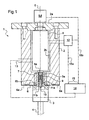
- the illustrated drilling head 1 comprises a support 2 and a tool holder 3 for holding a drill bit 4 coaxial with an axis 5 of rotation of the support 2.
- the support By its end 2a the support is coupled to a drive motor M schematically represented and whose axis of rotation is coaxial with the axis 5 which is also the longitudinal axis of the support 2.
- the tool holder 3 is fixed to the support 2 by a washer 6 which has the property of transmitting a torque between the support and the tool holder and which is elastically deformable in the direction of the axis 5.
- a washer 6 which has the property of transmitting a torque between the support and the tool holder and which is elastically deformable in the direction of the axis 5.
- An example of a such washer is described in the document EP 994 758 .
- This washer 6 is fixed by peripheral screws 6a to the support 2 while the tool holder 3 is fixed to the washer 6 by central screws 6b.
- the tool holder 3 has a central portion 3a which is guided to slide axially in a bearing 7 of the support.
- the support 2 is hollow and contains in its central recess 2b a piezoelectric actuator 8 whose oscillations, generated by a variable voltage applied thereto, are oriented along the axis 5.
- the upper end of this actuator in which the piezoelectric elements are enclosed in a housing which ensures their preloading, is fixed to the support at its upper part 2a. Its lower part is fixed to the part 3a of the tool holder.
- This attachment is provided by a longitudinal coupling member 9, having properties of recovery of bending stresses (necessarily existing because of the games and imperfections in the bearing 7) while allowing the transmission of reciprocating movements.
- This member 9 connects the vibrating end 8a of the actuator to a pivot 10 which is wedged in translation in the portion 3a of the tool holder by means of two thrust bearings 11a and 11b which allow to decouple the actuator 8 in torsion of the tool holder 3 in case of breakage of the washer 6.
- the control power supply of the piezoelectric actuator has been symbolized at 12. Depending on the case, it can be of the non-contact type (rotary transformer + integrated electronics) or with contact (type rotating commutator based on sliding contacts).
- the active element of the actuator is a sensor of the axial forces that it undergoes.
- the output of this sensor is noted 13 in the figure. It will be of the type without or with contact as in the case of the supply of energy to the actuator 8.
- the transmitted signals are directed to a processing unit 14 which outputs an actuator control signal which will be function of the input signal. It is known that the input signal is significant of the axial load applied to the actuator; it is therefore a representation of the force resistant to the penetration of the tool in the workpiece being machined so the nature of the material worked.
- a variation in this signal corresponds, for example, for a multilayer piece, to the crossing of an interface which can cause a change in the conduct of the drilling operation, not only in the control of the actuator ( by a transmission path 15a towards the actuator or the source of sound power supply) but also at the motor rotation drive motor M (by another transmission path 15b from the output 15 of the unit 14) and at the speed of penetration of the drill into the workpiece this, as a function, for example, of setpoints which are stored in the unit 14.
- the output of the sensor will preferably be treated without contact, by any appropriate means (transponder or other) to transfer the signals from a rotating sensor to a fixed processing unit and feed the sensor if necessary. It is moreover not outside the scope of the invention to provide all or part of the signal processing unit, embedded in the tool holder.
- the support 2 is coupled to the machine member M which can be a rotating shaft from a motor or a fixed part if for example the workpiece rotates about the axis 5.
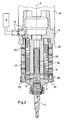
- the support 2 accommodates a tail 3a of the tool holder 3 by a cage or ball bushing 20 which provides axial guidance (sliding pivot) of the tool holder 3 in the support 2.
- This guidance is provided inside the actuator 8 which is here tubular , without preload (raw piezoelectric material).
- the means for measuring the axial force is here represented in the form of a strain gauge 21 extending along an external generator of the actuator 8.
- These means here comprise an outer sleeve 22 screwed into the support 2 by one of its ends while its other end is coupled by screws 23 to the tool holder 3.
- This sleeve has the characteristic of being very stiff in torsion and relatively flexible in the axial direction, having an axial stiffness imposed. For this purpose, it is notched circumferentially with a multitude of slots 24 which make it elastically axially while retaining its torsional stiffness. The number and the dimensions of the slots will be determined so as to ensure an axial elastic characteristic which will be calculated so as to perform the preload which will be applied to the actuator 8. This characteristic will however be compatible with the vibration energy so as not to overly dissipate this energy, for example by too much axial stiffness with regard to these efforts.
- the slots can be filled with a material with high thermal conductivity to drain the heat released by the actuator in operation.
- the sleeve 22 serves firstly, to suspend the tool holder to the support and, secondly, to transmit the torsional moments from the cutting forces from one to the other, while performing the necessary precharge for the actuator.
- Other geometric shapes than that described above are possible for the sleeve 22, to ensure all of these functions.
- this sleeve may comprise an alternating succession of internal and external grooves which give it the appearance of a gusset of axial stiffness determined.
- the coupling means also comprise an annular wedge 25 which is interposed and clamped between one end of the actuator 8 and the tool holder 3.
- the material and the geometry of this wedge 25 will be chosen so that the transmission of the axial oscillations generated by the actuator 8 is kept while minimizing the bending stresses resulting from the effort of cut, which could pass through the sliding pivot connection which necessarily includes a functional game so minimal it is.
- the geometry of this wedge 25 it will be noted that it is provided with cutouts in planes parallel and perpendicular to the axis 5 which define two parts in this wedge interconnected in the manner of a cardan link allowing micromovements so on small amplitudes, flexural flexibility that protects the piezoelectric actuator.
- the toolholder 3 is traversed by a channel C made along its axis, allowing the passage of any cooling agents and lubrication of the cutting area.
- These coolants can also be used to improve thermal drainage of the actuator. Different sealing means and orifices made in the adjoining rooms could then be practiced to bring this agent into contact with the actuator, so as to cause forced cooling.
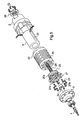
- FIG. 4 The embodiment shown in figures 4 and 5 is very similar to the one just described. The difference is due to the presence of a first additional element in the coupling means between the support and the tool holder.
- This element 26 is similar to element 6 of the figure 1 in the sense that it ensures, together with the sleeve 22, the suspension of the tool holder 3 to the support 2 and adds a radial stiffness to the connection, at the end of the tool holder opposite the tool, which contributes to avoid lateral micromovements that might be allowed by play in the sliding pivot connection.
- the torque transmission continues to be provided by the sleeve 22, even if the element 26 also participates when it is present.
- a second element or washer 27 similar to that 26, which has recesses 27a through which reliefs 25a of the annular ring 25 pass through the washer to reach the support on the tool holder 3.
- the recesses separating the reliefs in the wedge 25 are of sufficient size to be greater than the amplitude of the vibrations of the 8 actuator transmitted to the tool holder 3 by the wedge 25, so as to avoid at any time the contact between the wedge 25 and the washer 27.
- the washer 27 is rigidly secured by the outer screws 27 to the sleeve 22 and the holder 3 and suitably (special screw 27b) to the axis of the support 2.
- the role of the washer 27 and also to add a radial stiffness at the end of the tool holder located on the tool side, so to achieve together with the piece 26 a sliding connection by flexible guide, suitable for low amplitude movements.
- the axial stiffness of the sleeve 22 is dependent on the preload force that it is desired to impose on the actuator 8. This force corresponds to the difference in position along the axis 5 between the face of the door tool-turned towards the wedge 25 and towards the sleeve 22 and the free end of this sleeve, before its fixing by the screws 23. This difference in position before mounting of the two aforementioned faces form a mounting set which will be determined by the design and the precise realization of the pieces.
- the fastening by the screws 23 will cause the elastic elongation of the sleeve 22 and consequently the compression (determined by the value of the mounting clearance and the axial stiffness of the sleeve 22) of the actuator stack 8 / shim 25.
- the invention makes it possible to solve in a simple manner the splitting of the chips of a piercing tool and to control this fractionation and more generally the parameters of the operation to a detection of the nature of the treated material and this, in the case of a piezoelectric actuator in particular, with the same active member.
Landscapes
- Engineering & Computer Science (AREA)
- Mechanical Engineering (AREA)
- Drilling And Boring (AREA)
- Cutting Tools, Boring Holders, And Turrets (AREA)
Description
- La présente invention concerne une tête de perçage équipée d'un générateur d'oscillations (vibrations) axiales.
- Une machine de perçage présente l'inconvénient de produire des copeaux longs qui engendrent différents problèmes sur l'opération de perçage car ils sont difficiles à éloigner rapidement de la zone de travail et peuvent détériorer la qualité de la surface du trou fabriqué.
- Un remède à cet inconvénient consiste à provoquer la fragmentation de ces copeaux par variation de leur épaisseur et l'interruption répétée de la coupe. Celle-ci est obtenue en imposant à l'outil de coupe, généralement un foret, une vibration axiale qui rend la vitesse d'avance (de pénétration dans la matière) cycliquement variable donc l'épaisseur du copeau variable, avec des amplitudes et des fréquences qui conduisent à la fragmentation des copeaux.
- En même temps, il existe des opérations de perçage pour lesquelles on a l'intérêt de faire vibrer l'outil uniquement à certains moments (lors du perçage de matériaux multicouches, par exemple) ou de changer les amplitudes et/ou les fréquences des oscillations en temps réel (pour réagir et adapter le processus de coupe au matériau percé par exemple). Il est nécessaire alors d'avoir un dispositif capable d'être piloté, avec une réaction suffisamment rapide et la capacité de saisir le passage d'un matériau à l'autre.
- Plusieurs dispositifs qui utilisent les oscillations axiales en perçage ont déjà été proposés. On citera par exemple le dispositif décrit dans le document
EP 994 758 - Par un autre document
DE 103 43 682 , on connaît un outil de fraisage ou de perçage dans lequel on soumet l'outil tournant à un mouvement axial alternatif au moyen d'un actionneur piézoélectrique ou magnétique logé dans le porte outil, relié sans fil à une alimentation. Le système est commandé à distance. Cet outil est destiné à l'usinage des matériaux composites avec des fréquences de vibration axiales très élevées (ultrasoniques) à des très faibles amplitudes. - Par un autre document
U52008/041604 , on connaît un outil à tête oscillante dans lequel on soumet l'outil tournant à une oscillation à très haute fréquence, qui doit être égale à la fréquence propre de l'outil, de sorte que l'oscillation générée provoque une résonance axiale de l'outil. Les actionneurs des solutions décrites dans le documentUS2008/041604 sont intégrés complètement dans la partie axialement mobile des dispositifs, ne pouvant pas générer des déplacements et efforts statiques ou à basse fréquence à des amplitudes suffisantes pour fragmenter les copeaux. De plus, s'agissant de l'utilisation d'une résonance, les caractéristiques des oscillations obtenues dépendent fortement de la charge, c'est-à-dire de l'effort de pénétration rencontré lors de l'opération d'usinage. - Il est également connu du document
US2006/251480 une tête de perçage à oscillations axiales comportent un support d'accouplement à la tête d'un moteur d'entraînement en rotation de ce support d'accouplement qui comporte un porte outil suspendu de manière élastique suivant une direction axiale de l'outil. Un actionneur linéaire du support d'accouplement réalise une modulation linéaire de l'outil par la rotation. - Les dispositifs connus ne présentent pas toutes les qualités nécessaires à une machine qui soit d'usage universel en ce qui concerne la fragmentation du copeau en perçage par superposition d'oscillations axiales au mouvement d'avance de l'outil, c'est-à-dire qui soit robuste, qui puisse générer des oscillations axiales d'amplitudes suffisantes pour fragmenter les copeaux, qui puisse s'adapter sur des machines existantes et qui puisse disposer d'une faculté d'adaptation à différents programmes de perçage, notamment pour tenir compte des différents matériaux traversés dans une même opération. Il est connu par exemple que les oscillations générées par les dispositifs décrits dans
EP 999 758 US2008/041604 sont sensibles à la charge, c'est-à-dire qu'elles dépendent des diamètres et conditions de coupe (outils, paramètres de coupe etc.). Il est également connu que les actionneurs piézoélectriques sont fragiles et ne supportent pas les sollicitations autres que les efforts de compression. - A cet effet, la présente invention a pour objet une tête de perçage à générateur d'oscillations axiales, comportant un support d'accouplement de la tête à un moteur d'entraînement en rotation du support autour d'un axe, le support possédant un axe longitudinal en coïncidence avec l'axe de rotation du moteur, un porte-outil, des moyens de suspension élastiquement déformables du porte-outil au support qui sont capables de transmettre les moments de torsion et des moyens de guidage du porte-outil dans le support, le long de l'axe longitudinal de ce support, comportant un générateur commandé de mouvements alternatifs (oscillations) dans la direction de l'axe susdit, interposé entre le support et le porte-outil.
- Le générateur d'oscillations (appelé également l'actionneur) est tubulaire de type piézoélectrique en appui sur le support du porte-outil par l'une de ses extrémités tandis que la tête de perçage selon l'invention comprend un pivot glissant entre le support et le porte-outil, réalisé à l'intérieur du générateur tubulaire, un manchon extérieur axialement élastique et de grande raideur en torsion, fixé par ses extrémités respectivement au support et au porte-outil et une cale annulaire d'appui axial du porte-outil sur l'extrémité du générateur, de raideur axiale déterminée et de faible raideur en flexion.
- Le manchon et la cale servent à établir une précharge du générateur. La longueur de l'empilement du générateur et de la cale rapportée à la longueur libre du manchon extérieur et à sa caractéristique élastique en direction axiale permet d'ajuster la précharge du générateur. La cale annulaire, raide axialement, permet la transmission au porte-outil des vibrations issues du générateur alors que sa souplesse en flexion préserve le générateur des variations brutales des moments de flexion provenant du processus de perçage et des éventuels jeux du pivot glissant.
- Dans une variante de réalisation de cet exemple, la transmission du couple entre le support et le porte-outil est assurée par une liaison glissière entre le support et le porte-outil (douille à billes sur arbre profilé ou cannelé) de sorte que le manchon extérieur n'a plus comme fonction que d'assurer la précharge du générateur.
- La structure de ce manchon peut être composite avec de portions de paroi à haute conductivité thermique ou des évidements favorisant un drainage thermique de l'échauffement du générateur.
- Dans un autre exemple de réalisation, la tête de perçage comprend un pivot glissant entre le support et le porte-outil, à l'intérieur du générateur tubulaire, un manchon extérieur axialement élastique et de grande raideur en torsion fixé par ses extrémités respectivement au support et au porte-outil avec en parallèle au moins un élément plan, apte à transmettre des efforts radiaux, fixé entre le support et le porte-outil et une cale annulaire d'appui axial du porte-outil sur l'extrémité du générateur, de raideur axiale déterminée.
- Comme dans la réalisation précédente, la longueur de l'empilement du générateur et de la cale rapportée à la longueur libre du manchon extérieur et à sa caractéristique élastique en direction axile permet d'ajuster la précharge du générateur. La protection du générateur piézoélectrique contre les moments de torsion est assurée en parallèle par le manchon extérieur et l'élément souple susdit, qui soulagent la cale de devoir isoler en torsion le porte-outil du générateur ; cette disposition permet la reprise des efforts radiaux qui peuvent ne pas être repris par la liaison pivot glissant lorsqu'elle possède du jeu, même si ce jeu est faible. On peut mettre en oeuvre un autre élément plan de suspension du porte-outil au support en parallèle avec le premier donc également avec le manchon extérieur, cet autre élément plan étant situé au niveau de la cale d'appui, laquelle possède des reliefs qui traversent l'élément plan grâce à des évidements prévus à cet effet. Dans le cas où les deux éléments plans souples en direction axiale existent simultanément, ils forment un guidage axial de type glissière, adapté pour des faibles déplacements axiaux, et peuvent assurer la reprise des efforts radiaux, auquel cas la liaison pivot glissant à l'intérieur de l'actionneur tubulaire, assurée par une cage à billes par exemple, n'est plus absolument nécessaire. La présence de cette liaison (pivot glissant) permet néanmoins la mise en position plus aisée des éléments (porte-outil 3 et support 2), de manière précise, respectant une tolérance de coaxialité imposée, avant la mise en position en phase de montage des éléments de guidage élastique. Au cas où le guidage axial est réalisé uniquement par éléments de guidage élastique et on renonce à la liaison pivot glissant, un positionnement précis du porte-outil 3 par rapport au support 2 est nécessaire au montage.
- On préférera une transmission d'énergie sans contact par le biais de systèmes émetteurs récepteurs électromagnétiques (transformateur tournant). Toutefois, une connexion à contact pourrait être utilisée en employant un collecteur tournant.
- Dans une variante particulière du mode de réalisation de l'invention, le générateur peut intégrer un capteur pouvant indiquer la force qu'exerce axialement le foret sur la pièce au cours de l'usinage. Ce capteur peut effectuer une mesure directe de cet effort, par exemple utilisant l'effet piézoélectrique direct, à l'aide de quelques couches de matériau piézoélectrique, ou une mesure indirecte, par exemple de la déformation de l'actionneur (jauge de déformation, par exemple) auquel cas un traitement de signal est nécessaire pour déterminer l'effort de perçage. Il est ainsi possible de recueillir la variation de cette force et de l'exploiter pour le pilotage de l'actionneur ou même pour le pilotage des paramètres de coupe à l'aide de la machine utilisée (vitesse de coupe instantanée, vitesse d'avance). En effet, cette indication de la valeur instantanée de la force axiale mise en jeu dans l'opération de perçage constitue une variable interprétée par une unité de traitement de signaux pour modifier les paramètres de perçage à l'aide d'un modèle contenu dans un logiciel, fonctionnant sur une unité de traitement d'information (ordinateur, par exemple). Typiquement, la variation de cet effort axial sur le capteur-actionneur piézoélectrique, peut être interprétée comme le passage d'un matériau à l'autre dans un assemblage donné soumis au perçage. Par cette détection, l'unité de traitement peut modifier les paramètres de perçage au moment détecté du passage d'un matériau à l'autre et ainsi optimiser l'opération par référence à des programmes de perçage mémorisés.
- D'autres caractéristiques et avantages de l'invention ressortiront de la description donnée ci-après d'un exemple de réalisation de l'invention.
- Il sera fait référence aux dessins annexés dans lesquels :
- la
figure 1 représente en coupe, un dispositif de perçage à oscillations axiales connu de manière schématique, - la
figure 2 illustre par une coupe axiale, un premier mode de réalisation du dispositif conforme à l'invention, - la
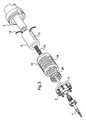
figure 3 est une vue éclatée des composants de lafigure 2 , - la
figure 4 est une vue en coupe axiale d'un deuxième mode de réalisation du dispositif de l'invention, - la
figure 5 est une vue éclatée du dispositif représenté à lafigure 4 . - A la
figure 1 , la tête de perçage représentée 1 comporte un support 2 et un porte-outil 3 pour maintenir un foret 4 coaxial à un axe 5 de rotation du support 2. - Par son extrémité 2a le support est attelé à un moteur d'entraînement M schématiquement représenté et dont l'axe de rotation est coaxial à l'axe 5 qui est aussi l'axe longitudinal du support 2.
- Le porte-outil 3 est fixé au support 2 par une rondelle 6 qui possède la propriété de transmettre un couple .entre le support et le porte-outil et qui est élastiquement déformable dans la direction de l'axe 5. Un exemple d'une telle rondelle est décrit dans le document
EP 994 758 - Le support 2 est creux et contient dans son évidement central 2b un actionneur piézoélectrique 8 dont les oscillations, engendrées par une tension variable qui lui est appliquée, sont orientée le long de l'axe 5. L'extrémité supérieure de cet actionneur, dans lequel les éléments piézoélectriques sont enfermés dans un boîtier qui assure leur précharge, est fixée au support au niveau de sa partie supérieure 2a. Sa partie inférieure est quant à elle fixée à la partie 3a du porte-outil. Cette fixation est assurée par un organe d'accouplement 9 longitudinal, ayant des propriétés de reprise des sollicitations en flexion (nécessairement existantes du fait des jeux et imperfections dans le palier 7) tout en autorisant la transmission des mouvements alternatifs. Cet organe 9 relie l'extrémité vibrante 8a de l'actionneur à un pivot 10 qui est calé en translation dans la partie 3a du porte-outil au moyen de deux butées à billes 11a et 11b qui permettent de découpler en torsion l'actionneur 8 du porte-outil 3 en cas de rupture de la rondelle 6.
- On a symbolisé en 12 l'alimentation de commande de l'actionneur piézoélectrique. Selon le cas, celle-ci peut être de type sans contact (transformateur tournant + électronique intégrée) ou avec contact (type collecteur tournant à base de contacts glissants).
- Il est avantageux de se servir d'une partie de l'élément actif de l'actionneur comme capteur des efforts axiaux qu'il subit. La sortie de ce capteur est notée 13 sur la figure. Elle sera du type sans ou avec contact comme dans le cas de l'apport d'énergie à l'actionneur 8. Les signaux émis sont dirigés vers une unité de traitement 14 qui émet en sortie 15 un signal de commande de l'actionneur qui sera fonction du signal d'entrée. On sait en effet que le signal d'entrée est significatif de la charge axiale appliquée à l'actionneur ; il est donc une représentation de l'effort résistant à la pénétration de l'outil dans la pièce en cours d'usinage donc à la nature du matériau travaillé. Une variation dans ce signal correspond, par exemple, pour une pièce multicouche, à la traversée d'une interface ce qui peut entraîner une modification de la conduite de l'opération de perçage, non seulement au niveau de la commande de l'actionneur (par un chemin de transmission 15a en direction de l'actionneur ou de la source de son alimentation) mais également au niveau du moteur M d'entraînement en rotation de l'outil (par un autre chemin de transmission 15b issu de la sortie 15 de l'unité 14) et au niveau de la vitesse de pénétration du foret dans la pièce et ce, en fonction, par exemple, de valeurs de consigne qui sont mémorisée dans l'unité 14. De même que pour la commande de l'actionneur, la sortie du capteur sera traitée de préférence sans contact, par tout moyen approprié (transpondeur ou autre) pour transférer les signaux d'un capteur tournant à une unité fixe de traitement et alimenter le capteur si nécessaire. Ce n'est d'ailleurs pas sortir du cadre de l'invention que de prévoir tout ou partie de l'unité de traitement des signaux, embarquée dans le porte-outil.
- Aux
figures 2 et3 , on retrouve la plupart des éléments déjà décrits avec les mêmes références. Le support 2 est attelé à l'élément de machine M qui peut être un arbre tournant issu d'un moteur ou une pièce fixe si par exemple la pièce à travailler tourne autour de l'axe 5. Le support 2 accueille une queue 3a du porte-outil 3 par une cage ou douille à billes 20 qui assure un guidage axial (pivot glissant) du porte-outil 3 dans le support 2. Ce guidage est assuré à l'intérieur de l'actionneur 8 qui est ici de forme tubulaire, sans précharge (matériau piézoélectrique brut). Le moyen de mesure de l'effort axial (capteur d'effort) est ici représenté sous la forme d'une jauge de contrainte 21 s'étendant le long d'une génératrice extérieure de l'actionneur 8. - L'essentiel de la différence de cette réalisation par rapport au schéma de la
figure 1 réside dans les moyens d'accouplement du porte-outil 3 au support 2 qui permettent de transmettre à la fois le couple provenant de l'opération de perçage et les oscillations axiales tout en préservant l'actionneur 8 des efforts de torsion ou de fléchissement qui nuirait à son fonctionnement. - Ces moyens comprennent ici un manchon extérieur 22 vissé dans le support 2 par l'une de ses extrémités tandis que son autre extrémité est attelée par des vis 23 au porte-outil 3. Ce manchon possède la caractéristique d'être très raide en torsion et relativement souple dans le sens axial, ayant une raideur axiale imposée. A cet effet, il est entaillé circonférenciellement d'une multitude de fentes 24 qui le rendent élastique axialement tout en lui conservant sa rigidité en torsion. Le nombre et les dimensions des fentes seront déterminés de manière à assurer une caractéristique élastique axiale qui sera calculée de manière à réaliser la précharge qui sera appliquée à l'actionneur 8. Cette caractéristique sera cependant compatible avec l'énergie de vibration pour ne pas trop dissiper cette énergie, par exemple par une raideur axiale trop importante en regard de ces efforts. Les fentes peuvent être remplies d'un matériau à forte conductivité thermique pour drainer la chaleur dégagée par l'actionneur en fonctionnement. Le manchon 22 sert d'une part, à suspendre le porte-outil au support et, d'autre part, à transmettre les moments de torsion provenant des efforts de coupe de l'un à l'autre, tout en réalisant la précharge nécessaire pour l'actionneur. D'autres formes géométriques que celle décrite précédemment sont possibles pour le manchon 22, afin d'assurer l'ensemble de ces fonctions. Ainsi, ce manchon peut comporter une succession alternée de gorges intérieures et extérieures qui lui confèrent l'aspect d'un soufflet de raideur axiale déterminée.
- Les moyens d'accouplement comprennent également une cale annulaire 25 qui est intercalée et pincée entre une extrémité de l'actionneur 8 et le porte-outil 3. Le matériau et la géométrie de cette cale 25 seront choisis pour que la transmission des oscillations axiales engendrées par l'actionneur 8 soit conservée tout en diminuant au maximum les sollicitations en flexion provenant de l'effort de coupe, qui pourraient transiter par la liaison pivot glissant qui comporte nécessairement un jeu fonctionnel si minime soit-il. Pour ce qui concerne la géométrie de cette cale 25, on notera qu'elle est pourvue de découpes dans des plans parallèles et perpendiculaires à l'axe 5 qui définissent deux parties dans cette cale relies entre elles à la manière d'une liaison cardan autorisant des micromouvements donc sur de petites amplitudes, une souplesse en flexion qui protège l'actionneur piézoélectrique.
- On remarquera dans cette solution le fait que le porte-outil 3 est traversé par un canal C pratiqué au long de son axe, permettant ainsi le passage des éventuels agents de refroidissement et lubrification de la zone de coupe. Ces agents de refroidissement peuvent aussi servir pour améliorer le drainage thermique de l'actionneur. Différents moyens d'étanchéité et des orifices pratiqués dans les pièces attenantes pourrait alors être pratiqués afin d'amener cet agent en contact avec l'actionneur, de manière à provoquer un refroidissement forcé.
- Le mode de réalisation représenté aux
figures 4 et5 est très semblable à celui qui vient d'être décrit. La différence tient à la présence d'un premier élément supplémentaire dans les moyens d'accouplement entre le support et le porte-outil. Cet élément 26 est semblable à l'élément 6 de lafigure 1 au sens où il assure, conjointement avec le manchon 22, la suspension du porte-outil 3 au support 2 et ajoute une raideur radiale à la liaison, au niveau de l'extrémité du porte-outil opposée à l'outil, ce qui contribue à éviter les micromouvements latéraux qui pourraient être permis par le jeu dans la liaison pivot glissant. La transmission du couple continue à être assurée par le manchon 22, même si l'élément 26 y participe également lorsqu'il est présent. - On remarquera la présence d'un deuxième élément ou rondelle 27, semblable à celui 26, qui possède des évidements 27a par lesquels des reliefs 25a de la bague annulaire 25 traversent la rondelle pour atteindre l'appui sur le porte-outil 3. Les creux séparant les reliefs dans la cale 25 sont de dimensions suffisantes pour être supérieures à l'amplitude des vibrations de l'actionneur 8 transmises au porte-outil 3 par la cale 25, de manière à éviter à tout moment le contact entre la cale 25 et la rondelle 27. La rondelle 27 est fixée rigidement par les vis extérieurs 27 au manchon 22 et au porte-outil 3 et de manière appropriée (vis spéciale 27b) à l'axe du support 2. Le rôle de la rondelle 27 et d'ajouter également une raideur radiale au niveau de l'extrémité du porte-outil situé du coté outil, de manière à réaliser ensemble avec la pièce 26 une liaison glissière par guidage flexible, adapté aux mouvements de faible amplitude.
- La raideur axiale du manchon 22 est tributaire de l'effort de précharge que l'on souhaite imposer à l'actionneur 8. C'est effort correspond en effet à la différence de position le long de l'axe 5 entre la face du porte-outil tournée vers la cale 25 et vers le manchon 22 et l'extrémité libre de ce manchon, avant sa fixation par les vis 23. Cette différence de position avant montage des deux faces susdites forme un jeu de montage qui sera déterminé par la conception et la réalisation précise des pièces. La fixation par les vis 23 provoquera l'allongement élastique du manchon 22 et par suite la compression (déterminée par la valeur du jeu de montage et la raideur axiale du manchon 22) de l'empilement actionneur 8 / cale 25.
- L'invention permet de résoudre de manière simple le fractionnement des copeaux d'un outil de perçage et d'asservir ce fractionnement et plus généralement les paramètres de l'opération à une détection de la nature du matériau traité et ce, dans le cas d'un actionneur piézoélectrique notamment, avec le même organe actif.
Claims (6)
- Tête de perçage (1) à générateur d'oscillations axiales, comportant un support (2) d'accouplement de la tête à un moteur d'entraînement en rotation du support autour d'un axe, le support (2) possédant un axe longitudinal (5) en coïncidence avec l'axe de rotation du moteur, un porte-outil (3), des moyens de suspension élastiquement déformables du porte-outil (3) au support (2), permettant des mouvements axiaux, et des moyens de guidage du porte-outil (3) dans le support (2), le long de l'axe longitudinal (5) de ce support, comportant un générateur (8) commandé de mouvements alternatifs dans la direction de l'axe (5) susdit, interposé entre le support (2) et le porte-outil (3), caractérisée en ce que le générateur (8) de mouvements axiaux alternatifs est tubulaire de type piézoélectrique sans précharge, en appui sur le support (2) du porte-outil par l'une de ses extrémités et en ce qu'elle comprend un pivot glissant (20) entre le support (2) et le porte-outil (3), à l'intérieur du générateur (8), un manchon extérieur (22) axialement élastique et de grande raideur en torsion fixé par ses extrémités respectivement au support (2) et au porte-outil (3) et une cale annulaire (25) d'appui axial du porte-outil (3) sur l'extrémité du générateur (8), de raideur axiale déterminée et de faible raideur en flexion, permettant la diminution des sollicitations nuisant au générateur (8), tout en autorisant la transmission des mouvements axiaux.
- Tête de perçage selon la revendication 1, caractérisée en ce que le manchon extérieur (22) et la cale annulaire (25) constituent le moyen d'installer une précharge axiale dans le générateur (8).
- Tête de perçage (1) à générateur d'oscillations axiales selon la revendication 1, caractérisée en ce qu'elle comprend une glissière (20) entre le support (2) et le porte-outil (3), à l'intérieur du générateur (8), permettant la transmission des moments de torsion entre le porte-outil (3) et le support (2), un manchon extérieur (22) axialement élastique fixé par ses extrémités respectivement au support (2) et au porte-outil (3) et une cale annulaire (25) d'appui axial du porte-outil (3) sur l'extrémité du générateur (8), de raideur axiale déterminée et de faible raideur en flexion, permettant la diminution des sollicitations nuisant au générateur (8), tout en permettant la transmission des mouvements axiaux.
- Tête de perçage (1) à générateur d'oscillations axiales selon la revendication 1, caractérisée en ce qu'elle comprend un pivot glissant (20) entre le support (2) et le porte-outil (3), à l'intérieur du générateur (8), un manchon extérieur (22) axialement élastique et de grande raideur en torsion fixé par ses extrémités respectivement au support (2) et au porte-outil (3) avec en parallèle au moins un élément plan (26,27), apte à transmettre des efforts radiaux, fixé entre le support (2) et le porte-outil (3) et une cale annulaire (25) d'appui axial du porte-outil (3) sur l'extrémité du générateur (8), de raideur axiale déterminée et de faible raideur en flexion.
- Tête de perçage (1) à générateur d'oscillations axiales selon la revendication 1, caractérisée en ce qu'elle comprend un manchon extérieur (22) axialement élastique et de grande raideur en torsion fixé par ses extrémités respectivement au support (2) et au porte-outil (3) avec deux éléments plans (26,27), montés en parallèle, aptes à transmettre des efforts radiaux, fixé entre le support (2) et le porte-outil (3), formant ainsi un guidage axial à éléments flexibles, et une cale annulaire (25) d'appui axial du porte-outil (3) sur l'extrémité du générateur (8), de raideur axiale déterminée et de faible raideur en flexion, permettant la diminution des sollicitations nuisant au générateur (8), tout en permettant la transmission des mouvements axiaux.
- Tête de perçage selon la revendication 1, caractérisée en ce que l'actionneur (8) porte un capteur (21) de la force qu'exerce axialement le foret sur la pièce au cours de l'usinage.
Applications Claiming Priority (2)
| Application Number | Priority Date | Filing Date | Title |
|---|---|---|---|
| FR0902051A FR2944722B1 (fr) | 2009-04-28 | 2009-04-28 | Tete de percage a vibrations axiales |
| PCT/EP2010/055690 WO2010125090A1 (fr) | 2009-04-28 | 2010-04-28 | Tete de percage a vibrations axiales |
Publications (2)
| Publication Number | Publication Date |
|---|---|
| EP2429747A1 EP2429747A1 (fr) | 2012-03-21 |
| EP2429747B1 true EP2429747B1 (fr) | 2013-04-17 |
Family
ID=41402374
Family Applications (1)
| Application Number | Title | Priority Date | Filing Date |
|---|---|---|---|
| EP10717624.0A Not-in-force EP2429747B1 (fr) | 2009-04-28 | 2010-04-28 | Tete de percage a vibrations axiales |
Country Status (10)
| Country | Link |
|---|---|
| US (1) | US8926235B2 (fr) |
| EP (1) | EP2429747B1 (fr) |
| JP (1) | JP5519777B2 (fr) |
| CN (1) | CN102548690B (fr) |
| BR (1) | BRPI1015269A2 (fr) |
| CA (1) | CA2760063C (fr) |
| ES (1) | ES2421629T3 (fr) |
| FR (1) | FR2944722B1 (fr) |
| RU (1) | RU2525871C2 (fr) |
| WO (1) | WO2010125090A1 (fr) |
Cited By (1)
| Publication number | Priority date | Publication date | Assignee | Title |
|---|---|---|---|---|
| US10589729B2 (en) | 2015-11-05 | 2020-03-17 | Knorr-Bremse Systeme Fuer Nutzfahzeuge Gmbh | Pressure-limiting valve |
Families Citing this family (41)
| Publication number | Priority date | Publication date | Assignee | Title |
|---|---|---|---|---|
| US9782835B2 (en) * | 2010-03-11 | 2017-10-10 | Edison Industrial Innovation, Llc | Tool attachment and through spindle coolant systems for use with ultrasonic machining modules |
| US9669471B2 (en) * | 2010-03-11 | 2017-06-06 | Cumberland & Western Resources, Llc | Devices for isolating acoustic vibrations in metalworking systems |
| JP5622463B2 (ja) * | 2010-07-09 | 2014-11-12 | 株式会社スギノマシン | 穴あけ加工制御方法および穴あけ加工装置 |
| CN102059366B (zh) * | 2010-11-26 | 2012-12-12 | 长春轨道客车股份有限公司 | 钻深可变式断排屑深孔加工方法 |
| DE102011003785A1 (de) * | 2011-02-08 | 2012-08-09 | Robert Bosch Gmbh | Werkzeugspannsystem und Werkzeugmaschine mit einem Werkzeugspannsystem |
| DE102011052252A1 (de) * | 2011-07-28 | 2013-01-31 | Herrmann Ultraschalltechnik Gmbh & Co. Kg | Werkzeugkopf sowie Verfahren zur spanenden Bearbeitung |
| CN102974901B (zh) * | 2011-09-06 | 2016-04-20 | 北京南口轨道交通机械有限责任公司 | 柔性攻丝卡具 |
| FR2984192B1 (fr) * | 2011-12-16 | 2014-01-10 | Mitis | Procede d'usinage |
| MX351258B (es) * | 2012-04-03 | 2017-10-06 | Fundacion Tecnalia Res & Innovation | Dispositivo portaherramientas. |
| US10245652B2 (en) * | 2012-11-05 | 2019-04-02 | M4 Sciences Llc | Rotating tool holder assembly for modulation assisted machining |
| DE102013210199A1 (de) * | 2013-05-31 | 2014-12-04 | Sauer Ultrasonic Gmbh | Werkzeug |
| US20140374156A1 (en) * | 2013-06-19 | 2014-12-25 | Smith International, Inc. | Methods of reducing stress in downhole tools |
| FR3018712B1 (fr) * | 2014-03-20 | 2016-12-30 | Arts | Outil de percage a deux moteurs coaxiaux |
| EP3188863B8 (fr) * | 2014-09-05 | 2022-04-06 | Edison Industrial Innovation, LLC | Fixation d'outil et systèmes de refroidissement par broche destinés à être utilisés avec des modules d'usinage par ultrasons |
| DE202014007224U1 (de) * | 2014-09-11 | 2015-12-14 | Sauer Gmbh | Werkzeugmaschine |
| BR112017000787A2 (pt) | 2014-09-15 | 2017-11-21 | Halliburton Energy Services Inc | ?ferramenta de oscilação de fundo de poço e sistema e método para vibrar axialmente uma broca de perfuração de fundo de poço, e, ferramenta de sistema? |
| CA2952207C (fr) | 2014-09-15 | 2018-08-14 | Halliburton Energy Services, Inc. | Vibration de fond de trou pour forage souterrain ameliore |
| FR3027541B1 (fr) | 2014-10-22 | 2016-12-30 | Centre Technique Des Ind Mec | Dispositif d'usinage vibratoire ameliore |
| JP6106248B2 (ja) * | 2014-11-07 | 2017-03-29 | 東台精機股▲ふん▼有限公司Tongtai Machine & Tool Co.,Ltd. | 高周波振動を有する工作機械と検出/フィードバック信号の制御方法 |
| DE102015105338A1 (de) * | 2015-04-08 | 2016-10-27 | Lti Motion Gmbh | Werkzeugantrieb mit Spindelwelle und Betriebsverfahren |
| DE102015212810B4 (de) * | 2015-07-08 | 2023-10-19 | Sauer Gmbh | Vorrichtung zur Erzeugung einer Ultraschallschwingung eines Werkzeugs und zur Messung von Schwingungsparametern |
| US10603723B1 (en) * | 2015-08-27 | 2020-03-31 | M4 Sciences, Llc | Machining system spindle for modulation-assisted machining |
| DE102015216596C5 (de) * | 2015-08-31 | 2026-01-15 | Dmg Mori Ultrasonic Lasertec Gmbh | Werkzeughalter |
| US10232446B2 (en) * | 2015-11-16 | 2019-03-19 | Apex Brands, Inc. | Adaptive drilling with piezo-electric feed oscillator |
| KR101849538B1 (ko) * | 2016-05-04 | 2018-04-17 | 주식회사 하영테크 | 도광판 금형, 도광판 금형의 타공 장치, 및 도광판 |
| DE102016214498A1 (de) * | 2016-08-05 | 2018-02-08 | Schaeffler Technologies AG & Co. KG | Werkzeughalteeinrichtung und Verfahren zum Bohren |
| DE102016214699A1 (de) * | 2016-08-08 | 2018-02-08 | Sauer Gmbh | Verfahren und Vorrichtung zur Bearbeitung eines Werkstücks an einer numerisch gesteuerten Werkzeugmaschine |
| US10875138B1 (en) | 2016-08-09 | 2020-12-29 | M4 Sciences Llc | Tool holder assembly for machining system |
| WO2018158920A1 (fr) * | 2017-03-02 | 2018-09-07 | Big Daishowa株式会社 | Procédé de fixation de porte-outil et porte-outil |
| TWI666087B (zh) * | 2017-03-29 | 2019-07-21 | 國立中興大學 | 一種切削刀把 |
| CH713735A1 (de) * | 2017-04-21 | 2018-10-31 | Erowa Ag | Spannfutter. |
| US20180355668A1 (en) * | 2017-06-08 | 2018-12-13 | J & B Equipment Repair LLC | Vibrational drill head |
| CN108468541B (zh) * | 2018-04-24 | 2024-03-26 | 中国石油天然气集团有限公司 | 一种钻井模拟装置及方法 |
| TWI669185B (zh) * | 2018-08-28 | 2019-08-21 | 國立中興大學 | 非接觸式電能傳輸的高頻振動主軸系統及拘束件製程方法 |
| TWI690693B (zh) * | 2018-12-25 | 2020-04-11 | 施俊名 | 用以量測一旋轉物件於加工期間所具有之超音波振動的方法及超音波振動量測模組 |
| CN109887800A (zh) * | 2019-04-28 | 2019-06-14 | 江苏东源电器集团股份有限公司 | 防弹跳真空断路器 |
| DE102019122505A1 (de) * | 2019-08-21 | 2021-02-25 | Broetje-Automation Gmbh | Verfahren zur spanabhebenden Bearbeitung eines Werkstücks |
| CN111761084B (zh) * | 2020-04-26 | 2021-08-06 | 上海工程技术大学 | 一种偏心轮振动钻床 |
| CN112317775B (zh) * | 2020-10-14 | 2021-11-19 | 汇专机床有限公司 | 一种超声波加工设备及其超声波主轴 |
| JP7576385B2 (ja) * | 2021-03-11 | 2024-10-31 | 株式会社Subaru | 工具駆動装置及び被穿孔品の製造方法 |
| CN117505908B (zh) * | 2023-12-08 | 2026-03-24 | 河北工业职业技术学院 | 纵扭复合振动钻铰刀柄 |
Family Cites Families (19)
| Publication number | Priority date | Publication date | Assignee | Title |
|---|---|---|---|---|
| US2848672A (en) * | 1955-07-26 | 1958-08-19 | Harris Transducer Corp | Self-excited transducer |
| US2947886A (en) * | 1958-04-29 | 1960-08-02 | Gulton Ind Inc | Piezoelectric ultrasonic transducer |
| SU1313584A1 (ru) * | 1986-01-27 | 1987-05-30 | Предприятие П/Я В-2347 | Сверлильна головка |
| JP2710967B2 (ja) * | 1988-11-22 | 1998-02-10 | 株式会社日立製作所 | 集積回路装置の製造方法 |
| US5305556A (en) * | 1989-06-19 | 1994-04-26 | Kopp Verfahrenstechnik Gmbh | Method and apparatus for shaping the interior surfaces of bores |
| JPH03228507A (ja) * | 1990-01-30 | 1991-10-09 | Brother Ind Ltd | 工作機械 |
| JPH03234450A (ja) * | 1990-02-06 | 1991-10-18 | Brother Ind Ltd | 超音波加工機 |
| US5440190A (en) * | 1992-09-25 | 1995-08-08 | Olympus Optical Co., Ltd. | Ultrasonic motor |
| FR2765505B1 (fr) * | 1997-07-07 | 1999-08-27 | Inst Nat Polytech Grenoble | Tete de percage a effet vibratoire |
| NO321556B1 (no) * | 2002-04-30 | 2006-05-29 | Teeness As | Dempeanordning for demping av vibrasjoner |
| CN2584328Y (zh) * | 2002-12-13 | 2003-11-05 | 天津理工学院 | 一种用于深孔与难加工材料的振动钻头 |
| DE10343682B4 (de) | 2003-09-20 | 2015-09-10 | GFE-Gesellschaft für Fertigungstechnik und Entwicklung Schmalkalden/Chemnitz mbH | Mechatronisches Werkzeugsystem zur Fräs- und Bohrbearbeitung |
| WO2006002675A1 (fr) | 2004-07-02 | 2006-01-12 | Sauer Gmbh | Outil a tete oscillante |
| JP4528937B2 (ja) * | 2004-12-02 | 2010-08-25 | 株式会社 東北テクノアーチ | 計測・加工システム |
| US7587965B2 (en) * | 2005-05-03 | 2009-09-15 | Purdue Research Foundation | Tool holder assembly and method for modulation-assisted machining |
| US7350441B2 (en) * | 2005-11-15 | 2008-04-01 | 3M Innovative Properties Company | Cutting tool having variable movement at two simultaneously independent speeds in an x-direction into a work piece for making microstructures |
| FR2901163B1 (fr) * | 2006-05-17 | 2009-01-23 | Aeds Ccr | Dispositif de percage a vibrations axiales auto-entretenues |
| US7824247B1 (en) * | 2007-06-01 | 2010-11-02 | The United States Of America As Represented By The Administrator Of The National Aeronautics And Space Administration | Portable rapid and quiet drill |
| JP5148259B2 (ja) * | 2007-12-14 | 2013-02-20 | 株式会社 東北テクノアーチ | 加工装置 |
-
2009
- 2009-04-28 FR FR0902051A patent/FR2944722B1/fr not_active Expired - Fee Related
-
2010
- 2010-04-28 ES ES10717624T patent/ES2421629T3/es active Active
- 2010-04-28 BR BRPI1015269A patent/BRPI1015269A2/pt not_active Application Discontinuation
- 2010-04-28 JP JP2012507728A patent/JP5519777B2/ja not_active Expired - Fee Related
- 2010-04-28 WO PCT/EP2010/055690 patent/WO2010125090A1/fr not_active Ceased
- 2010-04-28 CN CN201080018987.XA patent/CN102548690B/zh not_active Expired - Fee Related
- 2010-04-28 CA CA2760063A patent/CA2760063C/fr active Active
- 2010-04-28 US US13/266,611 patent/US8926235B2/en active Active
- 2010-04-28 EP EP10717624.0A patent/EP2429747B1/fr not_active Not-in-force
- 2010-04-28 RU RU2011143862/02A patent/RU2525871C2/ru not_active IP Right Cessation
Cited By (1)
| Publication number | Priority date | Publication date | Assignee | Title |
|---|---|---|---|---|
| US10589729B2 (en) | 2015-11-05 | 2020-03-17 | Knorr-Bremse Systeme Fuer Nutzfahzeuge Gmbh | Pressure-limiting valve |
Also Published As
| Publication number | Publication date |
|---|---|
| EP2429747A1 (fr) | 2012-03-21 |
| US8926235B2 (en) | 2015-01-06 |
| ES2421629T3 (es) | 2013-09-04 |
| JP2012525265A (ja) | 2012-10-22 |
| CN102548690B (zh) | 2014-11-05 |
| JP5519777B2 (ja) | 2014-06-11 |
| BRPI1015269A2 (pt) | 2016-12-13 |
| RU2011143862A (ru) | 2013-06-10 |
| CA2760063C (fr) | 2016-08-23 |
| CA2760063A1 (fr) | 2010-11-04 |
| FR2944722A1 (fr) | 2010-10-29 |
| US20120107062A1 (en) | 2012-05-03 |
| WO2010125090A1 (fr) | 2010-11-04 |
| RU2525871C2 (ru) | 2014-08-20 |
| FR2944722B1 (fr) | 2014-10-10 |
| CN102548690A (zh) | 2012-07-04 |
Similar Documents
| Publication | Publication Date | Title |
|---|---|---|
| WO2010125090A1 (fr) | Tete de percage a vibrations axiales | |
| EP1982783B1 (fr) | Machine d'usinage | |
| EP3119556B1 (fr) | Machine d'usinage | |
| FR2901163A1 (fr) | Dispositif de percage a vibrations axiales auto-entretenues | |
| JP6592513B2 (ja) | 改良された振動加工装置 | |
| EP3389913A1 (fr) | Tete de soudage par friction malaxage avec des organes d'accouplement et au moins un element elastique | |
| EP3983170B1 (fr) | Broche a actionneurs piezoelectriques | |
| FR2978932A1 (fr) | Machine d'usinage | |
| EP2767357B1 (fr) | Procédé d'usinage d'un trou débouchant dans une pièce et dispositif d'usinage utilisé pour la mise en oeuvre dudit procédé | |
| FR3142547A1 (fr) | Procédé et dispositif de contrôle de la tension de serrage d’une fixation aéronautique | |
| WO2009027940A1 (fr) | Dispositif de guidage de precision dans une machine d'usinage de pieces cylindriques | |
| EP3003616B1 (fr) | Dispositif d'usinage vibratoire | |
| FR2616218A1 (fr) | Procede pour la detection et la mesure directe et en continu de l'usure des outils de coupe par sonde electrique incorporee | |
| KR101506741B1 (ko) | 무백래쉬 기어박스 구조 | |
| JP5354172B2 (ja) | 内面加工装置 | |
| FR2922130A1 (fr) | Support d'outil instrumente et porte-outil associe | |
| WO2011098738A1 (fr) | Porte-outil à couple de glissement réglable | |
| FR3048909A1 (fr) | Outil coupant rotatif a capteur d'epaisseur integre | |
| EP3084536B1 (fr) | Dispositif de contrôle du perçage ou du fraisurage d'une pièce de haute-précision | |
| EP4598702A2 (fr) | Systeme de travail de piece comprenant une machine-outil, et procede de travail correspondant | |
| FR2700128A1 (fr) | Chariot d'avance et machine de brochage comportant un tel chariot. |
Legal Events
| Date | Code | Title | Description |
|---|---|---|---|
| PUAI | Public reference made under article 153(3) epc to a published international application that has entered the european phase |
Free format text: ORIGINAL CODE: 0009012 |
|
| 17P | Request for examination filed |
Effective date: 20111122 |
|
| AK | Designated contracting states |
Kind code of ref document: A1 Designated state(s): AT BE BG CH CY CZ DE DK EE ES FI FR GB GR HR HU IE IS IT LI LT LU LV MC MK MT NL NO PL PT RO SE SI SK SM TR |
|
| DAX | Request for extension of the european patent (deleted) | ||
| GRAP | Despatch of communication of intention to grant a patent |
Free format text: ORIGINAL CODE: EPIDOSNIGR1 |
|
| GRAS | Grant fee paid |
Free format text: ORIGINAL CODE: EPIDOSNIGR3 |
|
| GRAA | (expected) grant |
Free format text: ORIGINAL CODE: 0009210 |
|
| AK | Designated contracting states |
Kind code of ref document: B1 Designated state(s): AT BE BG CH CY CZ DE DK EE ES FI FR GB GR HR HU IE IS IT LI LT LU LV MC MK MT NL NO PL PT RO SE SI SK SM TR |
|
| REG | Reference to a national code |
Ref country code: GB Ref legal event code: FG4D Free format text: NOT ENGLISH |
|
| REG | Reference to a national code |
Ref country code: CH Ref legal event code: EP |
|
| REG | Reference to a national code |
Ref country code: IE Ref legal event code: FG4D Free format text: LANGUAGE OF EP DOCUMENT: FRENCH |
|
| REG | Reference to a national code |
Ref country code: AT Ref legal event code: REF Ref document number: 606932 Country of ref document: AT Kind code of ref document: T Effective date: 20130515 |
|
| REG | Reference to a national code |
Ref country code: DE Ref legal event code: R096 Ref document number: 602010006367 Country of ref document: DE Effective date: 20130613 |
|
| REG | Reference to a national code |
Ref country code: ES Ref legal event code: FG2A Ref document number: 2421629 Country of ref document: ES Kind code of ref document: T3 Effective date: 20130904 |
|
| REG | Reference to a national code |
Ref country code: AT Ref legal event code: MK05 Ref document number: 606932 Country of ref document: AT Kind code of ref document: T Effective date: 20130417 |
|
| REG | Reference to a national code |
Ref country code: LT Ref legal event code: MG4D |
|
| REG | Reference to a national code |
Ref country code: NL Ref legal event code: VDEP Effective date: 20130417 |
|
| BERE | Be: lapsed |
Owner name: EUROPEAN AERONAUTIC DEFENCE AND SPACE COMPANY EAD Effective date: 20130430 Owner name: ARTS Effective date: 20130430 |
|
| PG25 | Lapsed in a contracting state [announced via postgrant information from national office to epo] |
Ref country code: AT Free format text: LAPSE BECAUSE OF FAILURE TO SUBMIT A TRANSLATION OF THE DESCRIPTION OR TO PAY THE FEE WITHIN THE PRESCRIBED TIME-LIMIT Effective date: 20130417 Ref country code: IS Free format text: LAPSE BECAUSE OF FAILURE TO SUBMIT A TRANSLATION OF THE DESCRIPTION OR TO PAY THE FEE WITHIN THE PRESCRIBED TIME-LIMIT Effective date: 20130817 Ref country code: SE Free format text: LAPSE BECAUSE OF FAILURE TO SUBMIT A TRANSLATION OF THE DESCRIPTION OR TO PAY THE FEE WITHIN THE PRESCRIBED TIME-LIMIT Effective date: 20130417 Ref country code: LT Free format text: LAPSE BECAUSE OF FAILURE TO SUBMIT A TRANSLATION OF THE DESCRIPTION OR TO PAY THE FEE WITHIN THE PRESCRIBED TIME-LIMIT Effective date: 20130417 Ref country code: PT Free format text: LAPSE BECAUSE OF FAILURE TO SUBMIT A TRANSLATION OF THE DESCRIPTION OR TO PAY THE FEE WITHIN THE PRESCRIBED TIME-LIMIT Effective date: 20130819 Ref country code: FI Free format text: LAPSE BECAUSE OF FAILURE TO SUBMIT A TRANSLATION OF THE DESCRIPTION OR TO PAY THE FEE WITHIN THE PRESCRIBED TIME-LIMIT Effective date: 20130417 Ref country code: SI Free format text: LAPSE BECAUSE OF FAILURE TO SUBMIT A TRANSLATION OF THE DESCRIPTION OR TO PAY THE FEE WITHIN THE PRESCRIBED TIME-LIMIT Effective date: 20130417 Ref country code: NO Free format text: LAPSE BECAUSE OF FAILURE TO SUBMIT A TRANSLATION OF THE DESCRIPTION OR TO PAY THE FEE WITHIN THE PRESCRIBED TIME-LIMIT Effective date: 20130717 Ref country code: GR Free format text: LAPSE BECAUSE OF FAILURE TO SUBMIT A TRANSLATION OF THE DESCRIPTION OR TO PAY THE FEE WITHIN THE PRESCRIBED TIME-LIMIT Effective date: 20130718 |
|
| PG25 | Lapsed in a contracting state [announced via postgrant information from national office to epo] |
Ref country code: LV Free format text: LAPSE BECAUSE OF FAILURE TO SUBMIT A TRANSLATION OF THE DESCRIPTION OR TO PAY THE FEE WITHIN THE PRESCRIBED TIME-LIMIT Effective date: 20130417 Ref country code: PL Free format text: LAPSE BECAUSE OF FAILURE TO SUBMIT A TRANSLATION OF THE DESCRIPTION OR TO PAY THE FEE WITHIN THE PRESCRIBED TIME-LIMIT Effective date: 20130417 Ref country code: BG Free format text: LAPSE BECAUSE OF FAILURE TO SUBMIT A TRANSLATION OF THE DESCRIPTION OR TO PAY THE FEE WITHIN THE PRESCRIBED TIME-LIMIT Effective date: 20130717 Ref country code: CY Free format text: LAPSE BECAUSE OF FAILURE TO SUBMIT A TRANSLATION OF THE DESCRIPTION OR TO PAY THE FEE WITHIN THE PRESCRIBED TIME-LIMIT Effective date: 20130417 Ref country code: HR Free format text: LAPSE BECAUSE OF FAILURE TO SUBMIT A TRANSLATION OF THE DESCRIPTION OR TO PAY THE FEE WITHIN THE PRESCRIBED TIME-LIMIT Effective date: 20130417 |
|
| REG | Reference to a national code |
Ref country code: IE Ref legal event code: MM4A |
|
| PG25 | Lapsed in a contracting state [announced via postgrant information from national office to epo] |
Ref country code: EE Free format text: LAPSE BECAUSE OF FAILURE TO SUBMIT A TRANSLATION OF THE DESCRIPTION OR TO PAY THE FEE WITHIN THE PRESCRIBED TIME-LIMIT Effective date: 20130417 Ref country code: SK Free format text: LAPSE BECAUSE OF FAILURE TO SUBMIT A TRANSLATION OF THE DESCRIPTION OR TO PAY THE FEE WITHIN THE PRESCRIBED TIME-LIMIT Effective date: 20130417 Ref country code: BE Free format text: LAPSE BECAUSE OF NON-PAYMENT OF DUE FEES Effective date: 20130430 Ref country code: DK Free format text: LAPSE BECAUSE OF FAILURE TO SUBMIT A TRANSLATION OF THE DESCRIPTION OR TO PAY THE FEE WITHIN THE PRESCRIBED TIME-LIMIT Effective date: 20130417 Ref country code: CZ Free format text: LAPSE BECAUSE OF FAILURE TO SUBMIT A TRANSLATION OF THE DESCRIPTION OR TO PAY THE FEE WITHIN THE PRESCRIBED TIME-LIMIT Effective date: 20130417 Ref country code: MC Free format text: LAPSE BECAUSE OF FAILURE TO SUBMIT A TRANSLATION OF THE DESCRIPTION OR TO PAY THE FEE WITHIN THE PRESCRIBED TIME-LIMIT Effective date: 20130417 |
|
| PLBE | No opposition filed within time limit |
Free format text: ORIGINAL CODE: 0009261 |
|
| STAA | Information on the status of an ep patent application or granted ep patent |
Free format text: STATUS: NO OPPOSITION FILED WITHIN TIME LIMIT |
|
| PG25 | Lapsed in a contracting state [announced via postgrant information from national office to epo] |
Ref country code: NL Free format text: LAPSE BECAUSE OF FAILURE TO SUBMIT A TRANSLATION OF THE DESCRIPTION OR TO PAY THE FEE WITHIN THE PRESCRIBED TIME-LIMIT Effective date: 20130417 Ref country code: RO Free format text: LAPSE BECAUSE OF FAILURE TO SUBMIT A TRANSLATION OF THE DESCRIPTION OR TO PAY THE FEE WITHIN THE PRESCRIBED TIME-LIMIT Effective date: 20130417 Ref country code: IT Free format text: LAPSE BECAUSE OF FAILURE TO SUBMIT A TRANSLATION OF THE DESCRIPTION OR TO PAY THE FEE WITHIN THE PRESCRIBED TIME-LIMIT Effective date: 20130417 |
|
| 26N | No opposition filed |
Effective date: 20140120 |
|
| PG25 | Lapsed in a contracting state [announced via postgrant information from national office to epo] |
Ref country code: IE Free format text: LAPSE BECAUSE OF NON-PAYMENT OF DUE FEES Effective date: 20130428 |
|
| REG | Reference to a national code |
Ref country code: DE Ref legal event code: R097 Ref document number: 602010006367 Country of ref document: DE Effective date: 20140120 |
|
| REG | Reference to a national code |
Ref country code: CH Ref legal event code: PL |
|
| PG25 | Lapsed in a contracting state [announced via postgrant information from national office to epo] |
Ref country code: CH Free format text: LAPSE BECAUSE OF NON-PAYMENT OF DUE FEES Effective date: 20140430 Ref country code: LI Free format text: LAPSE BECAUSE OF NON-PAYMENT OF DUE FEES Effective date: 20140430 |
|
| PG25 | Lapsed in a contracting state [announced via postgrant information from national office to epo] |
Ref country code: MT Free format text: LAPSE BECAUSE OF FAILURE TO SUBMIT A TRANSLATION OF THE DESCRIPTION OR TO PAY THE FEE WITHIN THE PRESCRIBED TIME-LIMIT Effective date: 20130417 |
|
| PG25 | Lapsed in a contracting state [announced via postgrant information from national office to epo] |
Ref country code: SM Free format text: LAPSE BECAUSE OF FAILURE TO SUBMIT A TRANSLATION OF THE DESCRIPTION OR TO PAY THE FEE WITHIN THE PRESCRIBED TIME-LIMIT Effective date: 20130417 |
|
| PG25 | Lapsed in a contracting state [announced via postgrant information from national office to epo] |
Ref country code: TR Free format text: LAPSE BECAUSE OF FAILURE TO SUBMIT A TRANSLATION OF THE DESCRIPTION OR TO PAY THE FEE WITHIN THE PRESCRIBED TIME-LIMIT Effective date: 20130417 |
|
| PG25 | Lapsed in a contracting state [announced via postgrant information from national office to epo] |
Ref country code: HU Free format text: LAPSE BECAUSE OF FAILURE TO SUBMIT A TRANSLATION OF THE DESCRIPTION OR TO PAY THE FEE WITHIN THE PRESCRIBED TIME-LIMIT; INVALID AB INITIO Effective date: 20100428 Ref country code: MK Free format text: LAPSE BECAUSE OF FAILURE TO SUBMIT A TRANSLATION OF THE DESCRIPTION OR TO PAY THE FEE WITHIN THE PRESCRIBED TIME-LIMIT Effective date: 20130417 Ref country code: LU Free format text: LAPSE BECAUSE OF NON-PAYMENT OF DUE FEES Effective date: 20130428 |
|
| REG | Reference to a national code |
Ref country code: FR Ref legal event code: PLFP Year of fee payment: 7 |
|
| REG | Reference to a national code |
Ref country code: FR Ref legal event code: PLFP Year of fee payment: 8 |
|
| REG | Reference to a national code |
Ref country code: FR Ref legal event code: PLFP Year of fee payment: 9 |
|
| PGFP | Annual fee paid to national office [announced via postgrant information from national office to epo] |
Ref country code: GB Payment date: 20220425 Year of fee payment: 13 Ref country code: FR Payment date: 20220421 Year of fee payment: 13 Ref country code: ES Payment date: 20220629 Year of fee payment: 13 Ref country code: DE Payment date: 20220420 Year of fee payment: 13 |
|
| REG | Reference to a national code |
Ref country code: DE Ref legal event code: R119 Ref document number: 602010006367 Country of ref document: DE |
|
| GBPC | Gb: european patent ceased through non-payment of renewal fee |
Effective date: 20230428 |
|
| PG25 | Lapsed in a contracting state [announced via postgrant information from national office to epo] |
Ref country code: GB Free format text: LAPSE BECAUSE OF NON-PAYMENT OF DUE FEES Effective date: 20230428 |
|
| PG25 | Lapsed in a contracting state [announced via postgrant information from national office to epo] |
Ref country code: GB Free format text: LAPSE BECAUSE OF NON-PAYMENT OF DUE FEES Effective date: 20230428 Ref country code: FR Free format text: LAPSE BECAUSE OF NON-PAYMENT OF DUE FEES Effective date: 20230430 Ref country code: DE Free format text: LAPSE BECAUSE OF NON-PAYMENT OF DUE FEES Effective date: 20231103 |
|
| REG | Reference to a national code |
Ref country code: ES Ref legal event code: FD2A Effective date: 20240531 |
|
| PG25 | Lapsed in a contracting state [announced via postgrant information from national office to epo] |
Ref country code: ES Free format text: LAPSE BECAUSE OF NON-PAYMENT OF DUE FEES Effective date: 20230429 |
|
| PG25 | Lapsed in a contracting state [announced via postgrant information from national office to epo] |
Ref country code: ES Free format text: LAPSE BECAUSE OF NON-PAYMENT OF DUE FEES Effective date: 20230429 |