EP2429050B1 - Methods, systems, and apparatus for detecting arc flash events using light and time discrimination - Google Patents
Methods, systems, and apparatus for detecting arc flash events using light and time discrimination Download PDFInfo
- Publication number
- EP2429050B1 EP2429050B1 EP11179728.8A EP11179728A EP2429050B1 EP 2429050 B1 EP2429050 B1 EP 2429050B1 EP 11179728 A EP11179728 A EP 11179728A EP 2429050 B1 EP2429050 B1 EP 2429050B1
- Authority
- EP
- European Patent Office
- Prior art keywords
- circuit breaker
- light
- controller
- current
- time period
- Prior art date
- Legal status (The legal status is an assumption and is not a legal conclusion. Google has not performed a legal analysis and makes no representation as to the accuracy of the status listed.)
- Not-in-force
Links
- 238000000034 method Methods 0.000 title claims description 17
- 238000001514 detection method Methods 0.000 claims description 24
- 230000004044 response Effects 0.000 claims description 6
- 230000003213 activating effect Effects 0.000 claims 1
- 239000004020 conductor Substances 0.000 description 33
- 238000010586 diagram Methods 0.000 description 4
- 238000009413 insulation Methods 0.000 description 4
- 230000000977 initiatory effect Effects 0.000 description 3
- 230000002238 attenuated effect Effects 0.000 description 2
- 230000023077 detection of light stimulus Effects 0.000 description 2
- 230000006870 function Effects 0.000 description 2
- 230000000116 mitigating effect Effects 0.000 description 2
- 230000005355 Hall effect Effects 0.000 description 1
- 230000033228 biological regulation Effects 0.000 description 1
- 230000015572 biosynthetic process Effects 0.000 description 1
- 230000008859 change Effects 0.000 description 1
- 230000003247 decreasing effect Effects 0.000 description 1
- 230000003111 delayed effect Effects 0.000 description 1
- 239000003989 dielectric material Substances 0.000 description 1
- 230000000694 effects Effects 0.000 description 1
- 230000004907 flux Effects 0.000 description 1
- 238000005259 measurement Methods 0.000 description 1
- 238000010297 mechanical methods and process Methods 0.000 description 1
- 230000007246 mechanism Effects 0.000 description 1
- 230000007935 neutral effect Effects 0.000 description 1
- 230000003287 optical effect Effects 0.000 description 1
- 230000001681 protective effect Effects 0.000 description 1
- 239000004065 semiconductor Substances 0.000 description 1
- 239000007787 solid Substances 0.000 description 1
- 230000001960 triggered effect Effects 0.000 description 1
- 238000013022 venting Methods 0.000 description 1
Images

Classifications
-
- G—PHYSICS
- G01—MEASURING; TESTING
- G01R—MEASURING ELECTRIC VARIABLES; MEASURING MAGNETIC VARIABLES
- G01R31/00—Arrangements for testing electric properties; Arrangements for locating electric faults; Arrangements for electrical testing characterised by what is being tested not provided for elsewhere
- G01R31/12—Testing dielectric strength or breakdown voltage ; Testing or monitoring effectiveness or level of insulation, e.g. of a cable or of an apparatus, for example using partial discharge measurements; Electrostatic testing
-
- H—ELECTRICITY
- H02—GENERATION; CONVERSION OR DISTRIBUTION OF ELECTRIC POWER
- H02H—EMERGENCY PROTECTIVE CIRCUIT ARRANGEMENTS
- H02H1/00—Details of emergency protective circuit arrangements
- H02H1/0007—Details of emergency protective circuit arrangements concerning the detecting means
- H02H1/0015—Using arc detectors
- H02H1/0023—Using arc detectors sensing non electrical parameters, e.g. by optical, pneumatic, thermal or sonic sensors
-
- H—ELECTRICITY
- H02—GENERATION; CONVERSION OR DISTRIBUTION OF ELECTRIC POWER
- H02H—EMERGENCY PROTECTIVE CIRCUIT ARRANGEMENTS
- H02H1/00—Details of emergency protective circuit arrangements
- H02H1/04—Arrangements for preventing response to transient abnormal conditions, e.g. to lightning or to short duration over voltage or oscillations; Damping the influence of DC component by short circuits in AC networks
Definitions
- the embodiments described herein relate generally to arc flash detection and mitigation and, more particularly, to arc flash detection systems for use in reducing nuisance detections.
- Known electric power circuits and switchgear generally have conductors that are separated by insulation, such as air, or gas or solid dielectrics. However, if the conductors are positioned too closely together, or if a voltage between the conductors exceeds the insulative properties of the insulation between the conductors, an arc can occur. The insulation between the conductors can become ionized, which makes the insulation conductive and enables arc formation.
- An arc flash is caused by a rapid release of energy due to a fault between two phase conductors, between a phase conductor and a neutral conductor, or between a phase conductor and a ground point.
- Arc flash temperatures can reach or exceed 20,000°C, which can vaporize the conductors and adjacent equipment.
- an arc flash can release significant energy in the form of heat, intense light, pressure waves, and/or sound waves, sufficient to damage the conductors and adjacent equipment.
- the current level of a fault that generates an arc flash is generally less than the current level of a short circuit, such that a circuit breaker generally does not trip or exhibits a delayed trip unless the circuit breaker is specifically designed to handle an arc fault condition.
- EP 2 149 953 A2 which forms the preambles of the independent claims discloses an arc flash system including a first sensor such as a photodetector and a second sensor that detects a circuit breaker parameter indicating the position of a contact arm in the circuit breaker.
- Standard circuit protection devices such as fuses and circuit breakers, generally do not react quickly enough to mitigate an arc flash.
- One known circuit protection device that exhibits a sufficiently rapid response is an electrical "crowbar," which utilizes a mechanical and/or electro-mechanical process by intentionally creating an electrical "short circuit” to divert the electrical energy away from the arc flash point. Such an intentional short circuit fault is then cleared by tripping a fuse or a circuit breaker.
- the intentional short circuit fault created using a crowbar may allow significant levels of current to flow through adjacent electrical equipment, thereby still enabling damage to the equipment.
- Light sensors may be used to detect the presence of light emitted during an arc flash.
- such sensors are often sensitive to low light levels such that they also detect non-arc-flash light and trigger a "nuisance trip" of a circuit protection device.
- a typical arc flash event can produce light with luminous flux on the order of 100,000 lux at a distance of three to four feet from the arc flash event, while known light sensors generally saturate at 700 lux or less.
- Light emitted by a circuit breaker during a trip, by space lighting, or by direct sunlight may cause the light sensor to falsely detect an arc flash event.
- reducing the amount of light released during a circuit breaker interruption can negatively affect circuit breaker performance.
- an arc flash detection system that reliably detects arc flash events and mitigates undesired nuisance trips of circuit protection devices.
- a method of operating a circuit breaker according to claim 9 includes detecting a light event using a light sensor and determining whether the light event originated from operation of the circuit breaker.
- a power equipment protection system in another aspect, includes a circuit breaker, a current sensor configured to measure a current through a circuit, a light sensor configured to detect a light event, and a controller communicatively coupled to the current sensor and to the light sensor, wherein the controller is configured to determine whether the light event originated from operation of the circuit breaker.
- a controller configured to use with a power equipment protection system.
- the controller includes a processor configured to receive a signal representative of a measured current level from a current sensor, receive a signal representative of a detection of a light event from a light sensor, and determine whether the light event originated from operation of a circuit breaker.
- Exemplary embodiments of methods, systems, and apparatus for use in detecting and mitigating arc flash events are described herein.
- the embodiments described herein facilitate more reliably detecting arc flash events in power distribution equipment enclosures using current and light by discriminating against light events that occur during a known trip time by a circuit breaker.
- Exemplary technical effects of methods, systems, and apparatus described herein enable more reliable detection of arc flash events such that the energy associated with such events can be diverted to a self-contained arc flash containment device.
- arc flash event the current through a circuit rises rapidly and light energy will typically be released almost immediately.
- a circuit breaker is used to mitigate such a rapid rise in current, the current level will persist in the circuit for a predetermined amount of time before the circuit breaker begins a circuit interruption and releases light energy.
- Embodiments described herein function such that, when a current rise is initially detected and if light is not detected after a predetermined time period, a secondary algorithm is used to determine whether the circuit breaker is initiating a circuit interruption or whether an arc flash event is occurring.
- a circuit breaker with a known trip response time of approximately 0.25 seconds will initiate a circuit interruption within a certain amount of time, such as 0.22 seconds.
- the embodiments described herein enable a detection device to detect a high current level during a certain time duration, and to determine whether light detection occurs outside of the time duration. Detection of a light event outside of the time duration may be associated with an arc flash event.
- Fig. 1 is a schematic block diagram of an exemplary arc flash detection device 100 for use in detecting an arc flash event using light and time discrimination.
- system 100 includes a current sensor 102 that measures a current level through a conductor (not shown in Fig. 1 ).
- current sensor 102 generates a signal proportional to the current level.
- Current sensor 102 may detect an AC current and generate an analog output signal or a bipolar output signal that duplicates the wave shape of the sensed current.
- current sensor 102 may detect an AC current and generate a unipolar output signal that is proportional to an average value of the sensed current or an RMS value of the sensed current.
- current sensor 102 may detect a DC current and generate a unipolar output signal that duplicates the wave shape of the sensed current, or may generate a digital output that switches when the sensed current exceeds a certain threshold.
- Exemplary current sensors include, without limitation, a current transformer, a Hall effect sensor, a resistive sensor, or any suitable sensor that is configured to detect a current level and to generate an output signal representative of the current level.
- system 100 includes a plurality of light sensors 104 that detect a light event.
- Equipment enclosures include a number of obstructions that effectively block light from at least some light sensors 104. Accordingly, in order to maintain adequate coverage, light sensors 104 are dispersed throughout the equipment enclosure in the vicinity of conductors. Light impinges on light sensor 104, including ambient light, light generated by a trip of a circuit breaker (not shown in Fig. 1 ), and/or light generated by an arc flash event. If the light is of sufficient intensity to saturate light sensor 104, then light sensor 104 generates a signal representative of the detection. For example, light sensor 104 may generate a signal proportional to a light level of the light event.
- light sensor 104 may generate a signal that indicates that the detection occurred, such as a change in the signal at when a specified level is detected.
- the signal is analyzed with respect to its relationship with a time-based relationship between a current level and detection of light to determine whether an arc flash event has occurred.
- the light is attenuated by a light filter (not shown) by a specified percentage. If the attenuated light is of sufficient intensity to saturate light sensor 104, then light sensor 104 generates the signal representative of the detection.
- the light filter enables system 100 to discriminate between nuisance light and light generated by an arc flash event.
- system 100 also includes a controller 106 that is coupled, such as communicatively coupled, to current sensor 102 and to light sensor 104.
- controller 106 includes a memory area 108 that is configured to store circuit breaker trip data, such as a plurality of current levels and a time period necessary for a circuit breaker to open at each current level.
- circuit breaker trip data such as a plurality of current levels and a time period necessary for a circuit breaker to open at each current level.
- the relationship between one or more current levels and a respective time period necessary for a circuit breaker to open may be stored in, for example, a memory map, a database, in tabular form, or in a text file.
- memory area 108 may store the current levels and the time periods in any suitable manner.
- memory 108 may include any suitable manner for relating the current levels to the time periods.
- Controller 106 also include a processor 110 coupled to memory area 108.
- Processor 110 receives the signals from current sensor 102 and light sensor 104, and analyzes the signals using the time-based correlation stored in memory area 108 to determine whether an arc flash event has occurred.
- processor 110 determines that an arc flash event has occurred, it outputs a signal to an arc containment device (not shown in Fig. 1 ) to mitigate damage to electrical distribution equipment by the arc flash event.
- processor 110 may determine whether an arc flash event has occurred based on other parameters in addition to light and current, such as sound, pressure, heat, or other suitable parameters detected by suitable sensors.
- processor refers generally to any programmable system including systems and microcontrollers, reduced instruction set circuits (RISC), application specific integrated circuits (ASIC), programmable logic circuits, and any other circuit or processor capable of executing the functions described herein.
- RISC reduced instruction set circuits
- ASIC application specific integrated circuits
- programmable logic circuits any other circuit or processor capable of executing the functions described herein.
- the above examples are exemplary only, and thus are not intended to limit in any way the definition and/or meaning of the term "processor.”
- memory area 108 stores program code and instructions, executable by processor 110, to control and/or monitor current sensor 102, light sensors 104, or any other device that is coupled to controller 106.
- Memory area 108 may include one, or more than one, forms of memory.
- memory area 108 can include random access memory (RAM), which can include non-volatile RAM (NVRAM), magnetic RAM (MRAM), ferroelectric RAM (FeRAM) and other forms of memory.
- RAM random access memory
- NVRAM non-volatile RAM
- MRAM magnetic RAM
- FeRAM ferroelectric RAM
- Memory area 108 may also include read only memory (ROM), flash memory and/or Electrically Erasable Programmable Read Only Memory (EEPROM). Any other suitable magnetic, optical and/or semiconductor memory, by itself or in combination with other forms of memory, may be included in memory area 108.
- Memory area 108 may also be, or include, a detachable or removable memory, including, but not limited to, a suitable cartridge, disk, CD ROM, DVD or USB memory
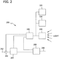
- Fig. 2 is a schematic block diagram of an exemplary power equipment protection system 200 that includes arc flash detection device 100.
- a line conductor 202 is coupled to a circuit breaker 204.
- Current sensor 102 is also coupled to line conductor 202 to measure a current level through line conductor 202.
- a load conductor 206 is coupled to a plasma-triggered arc containment device 208.
- Line conductor 202 may be a feeder line or a main bus line.
- Circuit breaker 204 operates a trip opening mechanism, such as a trip solenoid that releases a latch.
- the trip solenoid is typically energized by a separate battery, although some high-voltage circuit breakers are self-contained and include current transformers, protection relays, and an internal control power source.
- contacts within circuit breaker 204 open to interrupt current flow through line conductor 202.
- mechanically-stored energy such as a spring or compressed air, contained within circuit breaker 204 is used to separate the contacts. In some embodiments, a portion of the energy required may be obtained from the fault current.
- a signal is sent to a circuit protection device.
- an arc containment device 208 may be used to isolate the energy associated with the arc flash event. The energy associated with the detected arc flash is diverted away from line conductor 202 to arc containment device 208.
- a plasma gun (not shown) positioned within arc containment device 208 is activated to initiate a controlled and contained arc flash to facilitate protecting electrical components coupled to line conductor 202 and/or load conductor 206.
- controller 106 may cause circuit breaker 204 to trip.
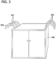
- Fig. 3 is a schematic illustration of a closed equipment enclosure 300
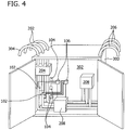
- Fig. 4 is a schematic illustration of an interior 302 of equipment enclosure 300.
- a plurality of line conductors 202 and a main bus 304 enter equipment enclosure 300, and a plurality of load conductors 206 exit equipment enclosure 300.
- power equipment protection system 200 is positioned within equipment enclosure 300 to facilitate preventing an arc flash event.
- current sensor 102 is positioned to monitor a current level through main bus 304.
- Light sensor 104 is positioned to monitor an amount of light in proximity to a conductor.
- light sensor 104 may be positioned to monitor an amount of light in proximity to main bus 304.
- equipment enclosure 300 may contain a plurality of arc detection devices 100, such as a first arc detection device for main bus 304 and a separate arc detection device for each line conductor 202.
- a first current sensor measures the current level through main bus 304 and a separate current sensor measures the current level through respective line conductors 202.
- a first light sensor detects light in proximity to main bus 304 and a separate light sensor detects light in proximity to respective line conductors 202.
- a plurality of light sensors 104 may be located throughout equipment enclosure 300, and be communicatively coupled to respective controllers 106.
- Circuit breaker 204 is positioned to enable a circuit interruption to be initiated in main bus 304 under control of controller 106. Moreover, in some embodiments, additional circuit breakers are positioned to enable a circuit interruption to be initiated in respective line conductors 202 under control of respective controllers 106. Moreover, arc containment device 208 is positioned to enable a rerouting of electrical energy when controller 106 detects an arc flash event. Alternatively, controller 106 may cause circuit breaker 204 to trip upon detection of an arc flash event.
- controller 106 measures a current level using current sensor 102.
- current sensor 102 measures, such as periodically measures, a current level through a conductor of main bus 304, for example.
- Current sensor 102 also transmits a signal representative of the current level to controller 106.
- multiple current sensors 102 may measure a current level through a conductor of each of main bus 304 and one or more line conductors 202, and transmit signals representative of the current levels to one or more controllers 106.
- controller 106 detects a light event using light sensor 104. For example, when a sufficient intensity of light impinges on light sensor 104, it transmits a signal indicative of the light event to controller 106.
- multiple light sensors 104 may be positioned to detect light events each of main bus 304 and one or more line conductors 202, and transmit signals representative of the detection of light events to one or more controllers 106.
- controller 106 determines whether the light event is originated from an arc flash event or whether the light event originated from operation of circuit breaker 204 using a relationship between current levels and timing of light events that is stored in memory area 108 (shown in Fig. 1 ).
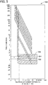
- Fig. 5 is a graph 500 that illustrates the relationship between current and timing of a trip of circuit breaker 204.
- the x -axis is a multiple of a current setting for circuit breaker 204 and the y -axis is a time measurement in seconds. For example, for a circuit breaker that is rated for 2,000 amperes, a value of 2 on the x -axis corresponds to a current of 4,000 amperes.
- circuit breaker 204 can be configured to trip based on a minimum band 502, an intermediate band 504, or a maximum band 506.
- intermediate band 504 as a reference, if circuit breaker 204 senses a current level sufficient to cause a trip, circuit breaker 204 initiates a circuit interruption.
- the circuit interruption occurs over a time period T that varies with the current level. For example, as shown in Fig. 5 , at a current level of approximately 4,000A, the circuit interruption occurs over a time period T that is between approximately 0.22 seconds and approximately 0.31 seconds.
- controller 106 determines the time period T that is associated with the current level received from current sensor 102.
- controller 106 determines that the light event occurred during the time period T, controller 106 enables circuit breaker 204 to complete the circuit interruption. However, if controller 106 determines that the light event occurred outside of the time period T, controller 106 activates arc containment device 208 (shown in Fig. 2 ) and/or causes circuit breaker 204 to trip. In some embodiments, controller 106 adds a preselected amount of time to the time period T to ensure that circuit breaker 204 is provided with enough time to complete the circuit interruption and to facilitate decreasing the opportunities for a nuisance trip.
- circuit breaker 204 transmits a signal to controller 106 that indicates to controller 106 that circuit breaker 204 is initiating a circuit interruption.
- Controller 106 determines from the time-based correlation stored in memory area 108 and illustrated in Fig. 5 , the time period T that is associated with completing the circuit interruption by circuit breaker 204. During the time period T, controller 106 does not activate arc containment device 208. Rather, controller 106 enables circuit breaker 204 to complete the circuit interruption.
- a rapid decrease in the measured current level can signify that circuit breaker 204 is initiating a circuit interruption.
- controller 106 detects a decrease in the current level, controller 106 does not activate arc containment device 208 during at least the time period T. Rather, controller 106 enables circuit breaker 204 to complete the circuit interruption.
- Exemplary embodiments of methods, systems, and apparatus for use in detecting an arc flash event using light and time discrimination are described above in detail.
- the methods, systems, and apparatus are not limited to the specific embodiments described herein but, rather, operations of the methods and/or components of the system and/or apparatus may be utilized independently and separately from other operations and/or components described herein. Further, the described operations and/or components may also be defined in, or used in combination with, other systems, methods, and/or apparatus, and are not limited to practice with only the systems, methods, and storage media as described herein.
Landscapes
- Physics & Mathematics (AREA)
- General Physics & Mathematics (AREA)
- Engineering & Computer Science (AREA)
- Power Engineering (AREA)
- Emergency Protection Circuit Devices (AREA)
- Arc-Extinguishing Devices That Are Switches (AREA)
- Locating Faults (AREA)
- Gas-Insulated Switchgears (AREA)
- Installation Of Bus-Bars (AREA)
- Photometry And Measurement Of Optical Pulse Characteristics (AREA)
Applications Claiming Priority (1)
| Application Number | Priority Date | Filing Date | Title |
|---|---|---|---|
| US12/877,181 US8564915B2 (en) | 2010-09-08 | 2010-09-08 | Methods, systems, and apparatus for detecting arc flash events using light and time discrimination |
Publications (3)
| Publication Number | Publication Date |
|---|---|
| EP2429050A2 EP2429050A2 (en) | 2012-03-14 |
| EP2429050A3 EP2429050A3 (en) | 2014-07-02 |
| EP2429050B1 true EP2429050B1 (en) | 2018-08-01 |
Family
ID=44772742
Family Applications (1)
| Application Number | Title | Priority Date | Filing Date |
|---|---|---|---|
| EP11179728.8A Not-in-force EP2429050B1 (en) | 2010-09-08 | 2011-09-01 | Methods, systems, and apparatus for detecting arc flash events using light and time discrimination |
Country Status (5)
| Country | Link |
|---|---|
| US (1) | US8564915B2 (enExample) |
| EP (1) | EP2429050B1 (enExample) |
| JP (1) | JP5890635B2 (enExample) |
| KR (1) | KR101806561B1 (enExample) |
| CN (1) | CN102403691B (enExample) |
Families Citing this family (22)
| Publication number | Priority date | Publication date | Assignee | Title |
|---|---|---|---|---|
| DE102011015066A1 (de) * | 2010-03-25 | 2012-01-12 | Abb Technology Ag | Schaltanlage für die Mittelspannung mit Kurzschließereinheit |
| US8797720B2 (en) * | 2011-09-13 | 2014-08-05 | Utility Relay Company | Manually-controlled arc flash energy reduction system and method for circuit breaker trip units |
| JP5889143B2 (ja) * | 2012-08-21 | 2016-03-22 | 三菱電機株式会社 | 太陽光発電システムおよびアーク検出保護装置 |
| US8964344B2 (en) * | 2012-08-24 | 2015-02-24 | Schneider Electric USA, Inc. | Circuit breaker signaling system for control of an arc fault detection system |
| US9053881B2 (en) | 2012-08-24 | 2015-06-09 | Schneider Electric USA, Inc. | Arc detection with resistance to nuisance activation through light subtraction |
| US9438028B2 (en) * | 2012-08-31 | 2016-09-06 | Schweitzer Engineering Laboratories, Inc. | Motor relay with integrated arc-flash detection |
| WO2014156945A1 (ja) * | 2013-03-29 | 2014-10-02 | 旭東電気株式会社 | アーク発生検知装置及び開閉器 |
| US9476795B1 (en) * | 2013-10-15 | 2016-10-25 | Nathaniel Group, Inc. | Optical-detection systems and methods for determining state of engagement of mating connectors, and equipment incorporating same |
| US9570901B2 (en) | 2014-02-17 | 2017-02-14 | Eaton Corporation | Electronic circuit and low voltage arc flash system including an electromagnetic trigger |
| US9570900B2 (en) | 2014-02-17 | 2017-02-14 | Eaton Corporation | Low voltage arc flash switch |
| CN106030949B (zh) * | 2014-02-19 | 2020-04-14 | 管理科学有限公司 | 用于在电力系统中保护免受不安全状态影响的系统 |
| GB2525266B (en) * | 2014-02-21 | 2020-11-18 | Cummins Power Generation Ip | Apparatus and method for providing protection against Arc flash in a generator set |
| CA2980153C (en) | 2015-03-24 | 2024-05-07 | Eaton Corporation | Arc flash mitigation switch for quenching external arc faults in low voltage switchgear |
| US10224706B2 (en) * | 2015-05-13 | 2019-03-05 | Nicholas Kreekon | Fuse box for mitigating arc faults and current surges |
| JP6776065B2 (ja) * | 2016-09-02 | 2020-10-28 | 株式会社東芝 | 内部アーク保護装置 |
| CN108414928B (zh) * | 2018-03-29 | 2023-05-26 | 广东电网有限责任公司 | 一种断路器线圈分合闸时间检测方法及装置 |
| JP7236637B2 (ja) * | 2019-05-29 | 2023-03-10 | パナソニックIpマネジメント株式会社 | アーク検出システム、アーク検出方法、プログラム、及び分電盤 |
| US11527878B2 (en) | 2020-10-14 | 2022-12-13 | Eaton Intelligent Power Limited | Hybrid arc flash mitigation system |
| US11482851B2 (en) | 2020-10-14 | 2022-10-25 | Eaton Intelligent Power Limited | Arc flash mitigation device |
| CN112213589A (zh) * | 2020-10-20 | 2021-01-12 | 国网江苏省电力有限公司 | 一种弧光保护装置的在线检测系统及方法 |
| US11855435B2 (en) * | 2021-12-13 | 2023-12-26 | Eaton Intelligent Power Limited | Arc flash accessory module |
| EP4462462A1 (en) * | 2023-05-12 | 2024-11-13 | Abb Schweiz Ag | Circuit breaker system with reduced own time: fault protection |
Family Cites Families (21)
| Publication number | Priority date | Publication date | Assignee | Title |
|---|---|---|---|---|
| US3391361A (en) | 1966-12-05 | 1968-07-02 | Gen Electric | Adjustable current-responsive device |
| US4791518A (en) * | 1986-06-09 | 1988-12-13 | Bbc Brown Boveri Ag | Device for detecting interfering arcs |
| FR2621748B1 (fr) * | 1987-10-09 | 1996-07-05 | Merlin Gerin | Declencheur statique d'un disjoncteur a boitier moule |
| JP2587913Y2 (ja) * | 1993-08-17 | 1998-12-24 | 日新電機株式会社 | ガス絶縁開閉装置事故区間検出装置 |
| JPH08235976A (ja) * | 1995-02-27 | 1996-09-13 | Takaoka Electric Mfg Co Ltd | ガス遮断器の故障検出装置 |
| US6229680B1 (en) * | 1999-08-16 | 2001-05-08 | Eaton Corporation | Apparatus and method for optically detecting arcing faults in electric power systems in the presence of other light sources |
| US6252365B1 (en) | 1999-08-17 | 2001-06-26 | General Electric Company | Breaker/starter with auto-configurable trip unit |
| AU2003217662A1 (en) | 2002-02-25 | 2003-09-09 | General Electric Company | Protection system for power distribution systems |
| CN100405684C (zh) * | 2003-08-04 | 2008-07-23 | 新巨企业股份有限公司 | 弧光放电保护装置 |
| US7035068B2 (en) * | 2003-12-05 | 2006-04-25 | Eaton Corporation | Apparatus and method employing an optical fiber for closed-loop feedback detection of arcing faults |
| US7203040B2 (en) | 2004-03-31 | 2007-04-10 | Gaton Corporation | Method and circuit breaker for reducing arc flash during maintenance in a low voltage power circuit |
| US7292422B2 (en) | 2004-11-29 | 2007-11-06 | Siemens Energy & Automation, Inc. | Occupancy-based circuit breaker control |
| US7646575B2 (en) | 2006-03-09 | 2010-01-12 | Utility Relay Co., Ltd. | Manually-controlled arc flash energy reduction system and method for circuit breaker trip units |
| US20080142486A1 (en) | 2006-12-19 | 2008-06-19 | Nataniel Barbosa Vicente | Circuit breaker with adjustable arc-flash protection and wireless sensor and method of use |
| US7821749B2 (en) * | 2007-03-30 | 2010-10-26 | General Electric Company | Arc flash elimination apparatus and method |
| WO2009020885A1 (en) * | 2007-08-03 | 2009-02-12 | Flir Systems, Inc. | Wireless remote detector systems and methods |
| JP5311619B2 (ja) * | 2008-03-14 | 2013-10-09 | 株式会社Nttファシリティーズ | 遮断器定格電流判定装置、遮断器定格電流判定システム、遮断器定格電流判定方法、およびプログラム |
| US7791846B2 (en) * | 2008-07-30 | 2010-09-07 | General Electric Company | Arc flash detection system, apparatus and method |
| US8803069B2 (en) * | 2008-09-19 | 2014-08-12 | Schweitzer Engineering Laboratories, Inc. | Electro-optical radiation collector for arc flash detection |
| MX2011002462A (es) * | 2008-09-19 | 2011-04-05 | Schweitzer Engineering Lab Inc | Deteccion segura de descarga por arco. |
| CA2736007C (en) * | 2008-09-19 | 2014-11-18 | Schweitzer Engineering Laboratories, Inc. | Protective device with metering and oscillography |
-
2010
- 2010-09-08 US US12/877,181 patent/US8564915B2/en active Active
-
2011
- 2011-09-01 EP EP11179728.8A patent/EP2429050B1/en not_active Not-in-force
- 2011-09-05 JP JP2011192472A patent/JP5890635B2/ja active Active
- 2011-09-06 CN CN201110278725.3A patent/CN102403691B/zh active Active
- 2011-09-07 KR KR1020110090578A patent/KR101806561B1/ko active Active
Non-Patent Citations (1)
| Title |
|---|
| None * |
Also Published As
| Publication number | Publication date |
|---|---|
| US8564915B2 (en) | 2013-10-22 |
| CN102403691B (zh) | 2016-05-11 |
| KR20120025999A (ko) | 2012-03-16 |
| KR101806561B1 (ko) | 2017-12-07 |
| JP5890635B2 (ja) | 2016-03-22 |
| JP2012060877A (ja) | 2012-03-22 |
| EP2429050A3 (en) | 2014-07-02 |
| EP2429050A2 (en) | 2012-03-14 |
| US20120057263A1 (en) | 2012-03-08 |
| CN102403691A (zh) | 2012-04-04 |
Similar Documents
| Publication | Publication Date | Title |
|---|---|---|
| EP2429050B1 (en) | Methods, systems, and apparatus for detecting arc flash events using light and time discrimination | |
| EP2424059B1 (en) | Methods, systems, and apparatus for detecting arc flash events using current and voltage | |
| US20140192458A1 (en) | Power distribution systems and methods of operating a power distribution system including arc flash detection | |
| CA2303964C (en) | Arc fault detection system for aircraft wiring | |
| KR101849407B1 (ko) | 차단기 상태를 이용한 아크 이벤트 검출 방법, 시스템 및 장치 | |
| JP5485607B2 (ja) | 回路遮断器及び、回路遮断器によりアークフラッシュを検出する方法 | |
| JP6194188B2 (ja) | 保護システム活性化および動的ラベリングのための方法、システムおよび装置 | |
| US7633729B2 (en) | Alternating current series arc fault detection method | |
| US9325167B2 (en) | Method, system, and apparatus for providing arc flash mitigation | |
| MXPA00012763A (es) | Operacion de bloqueo inhibicion de un sistema de deteccion de fallas por arco electrico. | |
| US20120050933A1 (en) | Branch circuit protection with in-line solid state device | |
| EP2115761A2 (en) | Configurable arc fault or ground fault circuit interrupter and method | |
| KR101315935B1 (ko) | 보호 디바이스 및 상기 보호 디바이스의 작동을 위한 방법 |
Legal Events
| Date | Code | Title | Description |
|---|---|---|---|
| AK | Designated contracting states |
Kind code of ref document: A2 Designated state(s): AL AT BE BG CH CY CZ DE DK EE ES FI FR GB GR HR HU IE IS IT LI LT LU LV MC MK MT NL NO PL PT RO RS SE SI SK SM TR |
|
| AX | Request for extension of the european patent |
Extension state: BA ME |
|
| PUAI | Public reference made under article 153(3) epc to a published international application that has entered the european phase |
Free format text: ORIGINAL CODE: 0009012 |
|
| PUAL | Search report despatched |
Free format text: ORIGINAL CODE: 0009013 |
|
| AK | Designated contracting states |
Kind code of ref document: A3 Designated state(s): AL AT BE BG CH CY CZ DE DK EE ES FI FR GB GR HR HU IE IS IT LI LT LU LV MC MK MT NL NO PL PT RO RS SE SI SK SM TR |
|
| AX | Request for extension of the european patent |
Extension state: BA ME |
|
| RIC1 | Information provided on ipc code assigned before grant |
Ipc: H02H 1/04 20060101ALN20140526BHEP Ipc: H02H 1/00 20060101AFI20140526BHEP |
|
| 17P | Request for examination filed |
Effective date: 20150105 |
|
| RBV | Designated contracting states (corrected) |
Designated state(s): AL AT BE BG CH CY CZ DE DK EE ES FI FR GB GR HR HU IE IS IT LI LT LU LV MC MK MT NL NO PL PT RO RS SE SI SK SM TR |
|
| 17Q | First examination report despatched |
Effective date: 20160929 |
|
| STAA | Information on the status of an ep patent application or granted ep patent |
Free format text: STATUS: EXAMINATION IS IN PROGRESS |
|
| GRAP | Despatch of communication of intention to grant a patent |
Free format text: ORIGINAL CODE: EPIDOSNIGR1 |
|
| STAA | Information on the status of an ep patent application or granted ep patent |
Free format text: STATUS: GRANT OF PATENT IS INTENDED |
|
| RIC1 | Information provided on ipc code assigned before grant |
Ipc: H02H 1/04 20060101ALN20180213BHEP Ipc: H02H 1/00 20060101AFI20180213BHEP |
|
| INTG | Intention to grant announced |
Effective date: 20180305 |
|
| GRAS | Grant fee paid |
Free format text: ORIGINAL CODE: EPIDOSNIGR3 |
|
| GRAA | (expected) grant |
Free format text: ORIGINAL CODE: 0009210 |
|
| STAA | Information on the status of an ep patent application or granted ep patent |
Free format text: STATUS: THE PATENT HAS BEEN GRANTED |
|
| AK | Designated contracting states |
Kind code of ref document: B1 Designated state(s): AL AT BE BG CH CY CZ DE DK EE ES FI FR GB GR HR HU IE IS IT LI LT LU LV MC MK MT NL NO PL PT RO RS SE SI SK SM TR |
|
| REG | Reference to a national code |
Ref country code: GB Ref legal event code: FG4D |
|
| REG | Reference to a national code |
Ref country code: CH Ref legal event code: EP Ref country code: AT Ref legal event code: REF Ref document number: 1025456 Country of ref document: AT Kind code of ref document: T Effective date: 20180815 |
|
| REG | Reference to a national code |
Ref country code: IE Ref legal event code: FG4D |
|
| REG | Reference to a national code |
Ref country code: DE Ref legal event code: R096 Ref document number: 602011050515 Country of ref document: DE |
|
| REG | Reference to a national code |
Ref country code: NL Ref legal event code: MP Effective date: 20180801 |
|
| REG | Reference to a national code |
Ref country code: LT Ref legal event code: MG4D |
|
| REG | Reference to a national code |
Ref country code: AT Ref legal event code: MK05 Ref document number: 1025456 Country of ref document: AT Kind code of ref document: T Effective date: 20180801 |
|
| PG25 | Lapsed in a contracting state [announced via postgrant information from national office to epo] |
Ref country code: AT Free format text: LAPSE BECAUSE OF FAILURE TO SUBMIT A TRANSLATION OF THE DESCRIPTION OR TO PAY THE FEE WITHIN THE PRESCRIBED TIME-LIMIT Effective date: 20180801 Ref country code: SE Free format text: LAPSE BECAUSE OF FAILURE TO SUBMIT A TRANSLATION OF THE DESCRIPTION OR TO PAY THE FEE WITHIN THE PRESCRIBED TIME-LIMIT Effective date: 20180801 Ref country code: IS Free format text: LAPSE BECAUSE OF FAILURE TO SUBMIT A TRANSLATION OF THE DESCRIPTION OR TO PAY THE FEE WITHIN THE PRESCRIBED TIME-LIMIT Effective date: 20181201 Ref country code: BG Free format text: LAPSE BECAUSE OF FAILURE TO SUBMIT A TRANSLATION OF THE DESCRIPTION OR TO PAY THE FEE WITHIN THE PRESCRIBED TIME-LIMIT Effective date: 20181101 Ref country code: NL Free format text: LAPSE BECAUSE OF FAILURE TO SUBMIT A TRANSLATION OF THE DESCRIPTION OR TO PAY THE FEE WITHIN THE PRESCRIBED TIME-LIMIT Effective date: 20180801 Ref country code: PL Free format text: LAPSE BECAUSE OF FAILURE TO SUBMIT A TRANSLATION OF THE DESCRIPTION OR TO PAY THE FEE WITHIN THE PRESCRIBED TIME-LIMIT Effective date: 20180801 Ref country code: FI Free format text: LAPSE BECAUSE OF FAILURE TO SUBMIT A TRANSLATION OF THE DESCRIPTION OR TO PAY THE FEE WITHIN THE PRESCRIBED TIME-LIMIT Effective date: 20180801 Ref country code: NO Free format text: LAPSE BECAUSE OF FAILURE TO SUBMIT A TRANSLATION OF THE DESCRIPTION OR TO PAY THE FEE WITHIN THE PRESCRIBED TIME-LIMIT Effective date: 20181101 Ref country code: GR Free format text: LAPSE BECAUSE OF FAILURE TO SUBMIT A TRANSLATION OF THE DESCRIPTION OR TO PAY THE FEE WITHIN THE PRESCRIBED TIME-LIMIT Effective date: 20181102 Ref country code: RS Free format text: LAPSE BECAUSE OF FAILURE TO SUBMIT A TRANSLATION OF THE DESCRIPTION OR TO PAY THE FEE WITHIN THE PRESCRIBED TIME-LIMIT Effective date: 20180801 Ref country code: LT Free format text: LAPSE BECAUSE OF FAILURE TO SUBMIT A TRANSLATION OF THE DESCRIPTION OR TO PAY THE FEE WITHIN THE PRESCRIBED TIME-LIMIT Effective date: 20180801 |
|
| RAP2 | Party data changed (patent owner data changed or rights of a patent transferred) |
Owner name: ABB SCHWEIZ AG |
|
| PG25 | Lapsed in a contracting state [announced via postgrant information from national office to epo] |
Ref country code: HR Free format text: LAPSE BECAUSE OF FAILURE TO SUBMIT A TRANSLATION OF THE DESCRIPTION OR TO PAY THE FEE WITHIN THE PRESCRIBED TIME-LIMIT Effective date: 20180801 Ref country code: AL Free format text: LAPSE BECAUSE OF FAILURE TO SUBMIT A TRANSLATION OF THE DESCRIPTION OR TO PAY THE FEE WITHIN THE PRESCRIBED TIME-LIMIT Effective date: 20180801 Ref country code: LV Free format text: LAPSE BECAUSE OF FAILURE TO SUBMIT A TRANSLATION OF THE DESCRIPTION OR TO PAY THE FEE WITHIN THE PRESCRIBED TIME-LIMIT Effective date: 20180801 Ref country code: ES Free format text: LAPSE BECAUSE OF FAILURE TO SUBMIT A TRANSLATION OF THE DESCRIPTION OR TO PAY THE FEE WITHIN THE PRESCRIBED TIME-LIMIT Effective date: 20180801 |
|
| REG | Reference to a national code |
Ref country code: DE Ref legal event code: R119 Ref document number: 602011050515 Country of ref document: DE |
|
| PG25 | Lapsed in a contracting state [announced via postgrant information from national office to epo] |
Ref country code: RO Free format text: LAPSE BECAUSE OF FAILURE TO SUBMIT A TRANSLATION OF THE DESCRIPTION OR TO PAY THE FEE WITHIN THE PRESCRIBED TIME-LIMIT Effective date: 20180801 Ref country code: IT Free format text: LAPSE BECAUSE OF FAILURE TO SUBMIT A TRANSLATION OF THE DESCRIPTION OR TO PAY THE FEE WITHIN THE PRESCRIBED TIME-LIMIT Effective date: 20180801 Ref country code: CZ Free format text: LAPSE BECAUSE OF FAILURE TO SUBMIT A TRANSLATION OF THE DESCRIPTION OR TO PAY THE FEE WITHIN THE PRESCRIBED TIME-LIMIT Effective date: 20180801 Ref country code: MC Free format text: LAPSE BECAUSE OF FAILURE TO SUBMIT A TRANSLATION OF THE DESCRIPTION OR TO PAY THE FEE WITHIN THE PRESCRIBED TIME-LIMIT Effective date: 20180801 Ref country code: EE Free format text: LAPSE BECAUSE OF FAILURE TO SUBMIT A TRANSLATION OF THE DESCRIPTION OR TO PAY THE FEE WITHIN THE PRESCRIBED TIME-LIMIT Effective date: 20180801 |
|
| REG | Reference to a national code |
Ref country code: CH Ref legal event code: PL |
|
| PG25 | Lapsed in a contracting state [announced via postgrant information from national office to epo] |
Ref country code: SK Free format text: LAPSE BECAUSE OF FAILURE TO SUBMIT A TRANSLATION OF THE DESCRIPTION OR TO PAY THE FEE WITHIN THE PRESCRIBED TIME-LIMIT Effective date: 20180801 Ref country code: DK Free format text: LAPSE BECAUSE OF FAILURE TO SUBMIT A TRANSLATION OF THE DESCRIPTION OR TO PAY THE FEE WITHIN THE PRESCRIBED TIME-LIMIT Effective date: 20180801 Ref country code: SM Free format text: LAPSE BECAUSE OF FAILURE TO SUBMIT A TRANSLATION OF THE DESCRIPTION OR TO PAY THE FEE WITHIN THE PRESCRIBED TIME-LIMIT Effective date: 20180801 |
|
| PLBE | No opposition filed within time limit |
Free format text: ORIGINAL CODE: 0009261 |
|
| STAA | Information on the status of an ep patent application or granted ep patent |
Free format text: STATUS: NO OPPOSITION FILED WITHIN TIME LIMIT |
|
| REG | Reference to a national code |
Ref country code: BE Ref legal event code: MM Effective date: 20180930 |
|
| REG | Reference to a national code |
Ref country code: IE Ref legal event code: MM4A |
|
| PG25 | Lapsed in a contracting state [announced via postgrant information from national office to epo] |
Ref country code: LU Free format text: LAPSE BECAUSE OF NON-PAYMENT OF DUE FEES Effective date: 20180901 |
|
| 26N | No opposition filed |
Effective date: 20190503 |
|
| GBPC | Gb: european patent ceased through non-payment of renewal fee |
Effective date: 20181101 |
|
| PG25 | Lapsed in a contracting state [announced via postgrant information from national office to epo] |
Ref country code: IE Free format text: LAPSE BECAUSE OF NON-PAYMENT OF DUE FEES Effective date: 20180901 Ref country code: DE Free format text: LAPSE BECAUSE OF NON-PAYMENT OF DUE FEES Effective date: 20190402 |
|
| PG25 | Lapsed in a contracting state [announced via postgrant information from national office to epo] |
Ref country code: FR Free format text: LAPSE BECAUSE OF NON-PAYMENT OF DUE FEES Effective date: 20181001 Ref country code: BE Free format text: LAPSE BECAUSE OF NON-PAYMENT OF DUE FEES Effective date: 20180930 Ref country code: LI Free format text: LAPSE BECAUSE OF NON-PAYMENT OF DUE FEES Effective date: 20180930 Ref country code: SI Free format text: LAPSE BECAUSE OF FAILURE TO SUBMIT A TRANSLATION OF THE DESCRIPTION OR TO PAY THE FEE WITHIN THE PRESCRIBED TIME-LIMIT Effective date: 20180801 Ref country code: CH Free format text: LAPSE BECAUSE OF NON-PAYMENT OF DUE FEES Effective date: 20180930 |
|
| PG25 | Lapsed in a contracting state [announced via postgrant information from national office to epo] |
Ref country code: GB Free format text: LAPSE BECAUSE OF NON-PAYMENT OF DUE FEES Effective date: 20181101 |
|
| PG25 | Lapsed in a contracting state [announced via postgrant information from national office to epo] |
Ref country code: MT Free format text: LAPSE BECAUSE OF NON-PAYMENT OF DUE FEES Effective date: 20180901 |
|
| PG25 | Lapsed in a contracting state [announced via postgrant information from national office to epo] |
Ref country code: TR Free format text: LAPSE BECAUSE OF FAILURE TO SUBMIT A TRANSLATION OF THE DESCRIPTION OR TO PAY THE FEE WITHIN THE PRESCRIBED TIME-LIMIT Effective date: 20180801 |
|
| PG25 | Lapsed in a contracting state [announced via postgrant information from national office to epo] |
Ref country code: PT Free format text: LAPSE BECAUSE OF FAILURE TO SUBMIT A TRANSLATION OF THE DESCRIPTION OR TO PAY THE FEE WITHIN THE PRESCRIBED TIME-LIMIT Effective date: 20180801 Ref country code: HU Free format text: LAPSE BECAUSE OF FAILURE TO SUBMIT A TRANSLATION OF THE DESCRIPTION OR TO PAY THE FEE WITHIN THE PRESCRIBED TIME-LIMIT; INVALID AB INITIO Effective date: 20110901 |
|
| PG25 | Lapsed in a contracting state [announced via postgrant information from national office to epo] |
Ref country code: MK Free format text: LAPSE BECAUSE OF NON-PAYMENT OF DUE FEES Effective date: 20180801 Ref country code: CY Free format text: LAPSE BECAUSE OF FAILURE TO SUBMIT A TRANSLATION OF THE DESCRIPTION OR TO PAY THE FEE WITHIN THE PRESCRIBED TIME-LIMIT Effective date: 20180801 |