EP2428913A2 - Objektklassifizierung für gemessene dreidimensionale Objektszenen - Google Patents
Objektklassifizierung für gemessene dreidimensionale Objektszenen Download PDFInfo
- Publication number
- EP2428913A2 EP2428913A2 EP11179804A EP11179804A EP2428913A2 EP 2428913 A2 EP2428913 A2 EP 2428913A2 EP 11179804 A EP11179804 A EP 11179804A EP 11179804 A EP11179804 A EP 11179804A EP 2428913 A2 EP2428913 A2 EP 2428913A2
- Authority
- EP
- European Patent Office
- Prior art keywords
- coordinates
- scene
- object scene
- value
- image
- Prior art date
- Legal status (The legal status is an assumption and is not a legal conclusion. Google has not performed a legal analysis and makes no representation as to the accuracy of the status listed.)
- Granted
Links
Images



Classifications
-
- G—PHYSICS
- G06—COMPUTING OR CALCULATING; COUNTING
- G06V—IMAGE OR VIDEO RECOGNITION OR UNDERSTANDING
- G06V20/00—Scenes; Scene-specific elements
- G06V20/60—Type of objects
- G06V20/64—Three-dimensional [3D] objects
-
- A—HUMAN NECESSITIES
- A61—MEDICAL OR VETERINARY SCIENCE; HYGIENE
- A61C—DENTISTRY; APPARATUS OR METHODS FOR ORAL OR DENTAL HYGIENE
- A61C9/00—Impression cups, i.e. impression trays; Impression methods
- A61C9/004—Means or methods for taking digitized impressions
- A61C9/0046—Data acquisition means or methods
- A61C9/0053—Optical means or methods, e.g. scanning the teeth by a laser or light beam
- A61C9/006—Optical means or methods, e.g. scanning the teeth by a laser or light beam projecting one or more stripes or patterns on the teeth
-
- A—HUMAN NECESSITIES
- A61—MEDICAL OR VETERINARY SCIENCE; HYGIENE
- A61B—DIAGNOSIS; SURGERY; IDENTIFICATION
- A61B1/00—Instruments for performing medical examinations of the interior of cavities or tubes of the body by visual or photographical inspection, e.g. endoscopes; Illuminating arrangements therefor
- A61B1/06—Instruments for performing medical examinations of the interior of cavities or tubes of the body by visual or photographical inspection, e.g. endoscopes; Illuminating arrangements therefor with illuminating arrangements
- A61B1/0605—Instruments for performing medical examinations of the interior of cavities or tubes of the body by visual or photographical inspection, e.g. endoscopes; Illuminating arrangements therefor with illuminating arrangements for spatially modulated illumination
-
- G—PHYSICS
- G06—COMPUTING OR CALCULATING; COUNTING
- G06V—IMAGE OR VIDEO RECOGNITION OR UNDERSTANDING
- G06V2201/00—Indexing scheme relating to image or video recognition or understanding
- G06V2201/03—Recognition of patterns in medical or anatomical images
Definitions
- the invention relates generally to three-dimensional imaging (3D) of an object scene. More particularly, the invention relates to a method of differentiating between different classes of objects in a 3D measurement of the object scene.
- a series of two-dimensional (2D) intensity images of one or more object surfaces in an object scene is acquired where the illumination for each image may vary.
- structured light patterns are projected onto the surface and detected in each 2D intensity image.
- the projected light pattern can be generated by projecting a pair of coherent optical beams onto the object surface and the resulting fringe pattern varied between successive 2D images.
- the projected light pattern may be a series of projected parallel lines generated using an intensity mask and the projected pattern shifted in position between successive 2D images.
- techniques such as confocal imaging are employed.
- a series of 3D data sets is acquired while the camera or scanner is in motion relative to the object scene.
- the imaging system can be a wand or other handheld device that a user manually positions relative to the object scene.
- multiple objects surfaces are measured by moving the device relative to the objects so that surfaces obscured from view of the device in one position are observable by the device in another position.
- a processing unit registers the overlapped region of all acquired 3D data to obtain a full 3D data set representation of all surfaces observed during the measurement procedure.
- measurements of an intra-oral cavity typically include 3D data for different classes of objects such as teeth, artificial dental structures and gingiva.
- the 3D data can be presented to a user in different graphical formats such as a display of the points in the form of a 3D surface map representation or in the form of a 3D point cloud.
- Differentiating between different structures represented in the display can be problematic and may require extensive effort to properly interpret features in the display.
- the clinician may be unable to distinguish adjacent portions of separate objects. For example, it can be difficult for a dental professional to accurately recognize the boundary between gingiva and enamel or dentin.
- the invention features a method of object classification for images of an intra-oral cavity.
- the method includes illuminating at least a portion of an intra-oral cavity with an optical beam and acquiring an image of the illuminated portion. Coordinates are determined for a plurality of points in the image and a translucence value is determined for each of the points. An object class is determined for each of the points based on the translucence value of the point.
- the invention features a method of object classification of 3D data for an object scene.
- the method includes illuminating an object scene with a structured light pattern and acquiring images of the illuminated object scene. Coordinates are determined for a plurality of points in the object scene based on the acquired images. A translucence value is determined for each point and an object class is determined for each point based on the translucence value of the point.
- the invention features a method of object classification of 3D data for an object scene.
- the method includes illuminating an object scene with a sequence of structured light patterns each having a different spatial phase.
- An image of the object scene is acquired for each of the structured light patterns.
- Coordinates are determined for a plurality of points in the object scene based on the acquired images.
- a background intensity value is determined for each point based on the acquired images and an object class is determined for each point based on the background intensity value for the point.
- the invention features an apparatus for object classification of an object scene.
- the apparatus includes an illumination source to illuminate an object scene, an imager and a processor in communication with the imager.
- the imager is configured to acquire an image of the illuminated object scene and to provide an output signal comprising 2D image data for the object scene.
- the processor is configured to determine a translucence value for a plurality of coordinates represented in the image in response to the 2D image data.
- the processor determines an object class for each of the coordinates in response to the translucence value for the coordinate.
- the invention features an apparatus for object classification of an object scene.
- the apparatus includes a projector, an imager and a processor in communication with the imager.
- the projector is configured to illuminate an object scene with a sequence of structured light patterns.
- the imager is configured to acquire an image of the illuminated object scene for each structured light patterns in the sequence.
- the imager provides an output signal comprising 2D image data for the object scene for each of the images.
- the processor is configured to determine 3D coordinates for the object scene and a translucence value for each of the 3D coordinates in response to the 2D image data for the sequence.
- the processor determines an object class for each of the 3D coordinates in response to the translucence value for the 3D coordinate.
- FIG. 1 is a block diagram showing an example of a measurement system that can be used to obtain a 3D image of an object scene.
- FIG. 2 illustrates a maneuverable wand that is part of a 3D measurement system used to obtain 3D measurement data for an intra-oral cavity.
- FIG. 3 illustrates how a 3D measurement of the upper dental arch is performed using the wand of FIG. 2 .
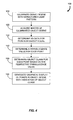
- FIG. 4 is a flowchart representation of a method of classification of 3D data for an object scene according to an embodiment of the invention.
- FIG. 5 is a flowchart representation of a method of object classification of 3D data for an object scene according to another embodiment of the invention.
- the methods of the present invention may include any of the described embodiments or combinations of the described embodiments in an operable manner.
- the methods of the invention enable rapid automated object classification of measured 3D object scenes.
- object classification refers to the determination of a type or class of object from a plurality of possible object classes for a measured object.
- the method can be performed during the 3D measurement procedure while data are being acquired. Alternatively, the method can be performed after completion of a measurement procedure with previously acquired data.
- an object scene is illuminated with an optical beam and an image is acquired. Coordinates are determined for points in the image and a translucence value is determined for each of the points.
- An object class is determined for each point based on the translucence value for the point.
- grayscale or color image data for each point is used to supplement the object class determination.
- the methods relate to object classification for 3D data during or after a 3D measurement of an oral cavity, such as a measurement made by a clinician in a dental application.
- Measured surfaces may include the enamel surface of teeth, the dentin substructure of teeth, gingiva, various dental structures (e.g., posts, inserts and fillings) and soft tissue (e.g., the tongue or lip).
- Classification of the 3D measurement data for the intra-oral measurement allows a distinction among the 3D data that correspond to these different object classes.
- the ability to distinguish among different types of objects allows the 3D measurement data to be displayed in a manner that shows the object class in the measured object scene.
- 3D measurement data from objects not of interest can be managed accordingly.
- motion of the tongue or lip through the measurement field of view in an intra-oral measurement application can cause data to be acquired from the interfering object.
- the unwanted data can be discarded or otherwise prevented from corrupting the measurement of the intended object scene, i.e., the teeth and gingiva.
- the methods can also be applied in medical applications and other applications in which 3D measurement data are acquired for object scenes having a plurality of object classes.
- 3D measurement systems use structured illumination patterns generated by interferometric fringe projection or other techniques.
- Imaging components acquire 2D images to determine coordinate information of points on the surface of objects based on the structured illumination of the objects.
- AFI Accordion Fringe Interferometry
- FIG. 1 illustrates an AFI-based 3D measurement system 10 used to obtain 3D images of one or more objects 22.
- Two coherent optical beams 14A and 14B generated by a fringe projector 18 are used to illuminate the surface of the object 22 with a pattern of interference fringes 26.
- An image of the fringe pattern at the object 22 is formed by an imaging system or lens 30 onto an imager that includes an array of photodetectors 34.
- the detector array 34 can be a two-dimensional charge coupled device (CCD) imaging array.
- An output signal generated by the detector array 34 is provided to a processor 38.
- the output signal includes information on the intensity of the light received at each photodetector in the array 34.
- An optional polarizer 42 is oriented to coincide with the main polarization component of the scattered light.
- a control module 46 controls parameters of the two coherent optical beams 14 emitted from the fringe projector 18.
- the control module 46 includes a phase shift controller 50 to adjust the phase difference of the two beams 14 and a spatial frequency controller 54 to adjust the pitch, or separation, of the interference fringes 26 at the object 22.
- the spatial frequency of the fringe pattern is determined by the separation of two virtual sources of coherent optical radiation in the fringe projector 18, the distance from the virtual sources to the object 22, and the wavelength of the radiation.
- the virtual sources are points from which optical radiation appears to originate although the actual sources of the optical radiation may be located elsewhere.
- the processor 38 and control module 46 communicate to coordinate the processing of signals from the photodetector array 34 with respect to changes in phase difference and spatial frequency, and the processor 38 determines 3D information for the object surface according to the fringe pattern images.
- the processor 38 calculates the distance from the imaging system 30 and detector array 34 to the object surface for each pixel based on the intensity values for the pixel in the series of 2D images generated after successive phase shifts of the fringe patterns. Thus the processor creates a set of 3D coordinates that can be displayed as a point cloud or a surface map that represents the object surface.
- the processor 38 communicates with a memory module 58 for storage of 3D data generated during a measurement procedure.
- a user interface 62 includes an input device and a display to enable an operator such as a clinician to provide operator commands and to observe the acquired 3D information in a near real-time manner. For example, the operator can observe a display of the growth of a graphical representation of the point cloud or surface map as different regions of the surface of the object 22 are measured and additional 3D measurement data are acquired.
- FIG. 2 illustrates a handheld 3D measurement device in the form of a maneuverable wand 66 that can be used to obtain 3D measurement data for an intra-oral cavity.
- the wand 66 includes a body section 70 that is coupled through a flexible cable 74 to a processor and other system components (not shown).
- the wand 66 generates a structured light pattern 78 that is projected from near the projection end 82 to illuminate the object scene to be measured.
- the structured light pattern 78 can be an interferometric fringe pattern based on the principles of an AFI measurement system as described above for FIG. 1 .
- the wand 66 can be used to obtain 3D data for a portion of a dental arch.
- the wand 66 is maneuvered within the intra-oral cavity by a clinician so that 3D data are obtained for all surfaces that can be illuminated by the structured light pattern 78.
- FIG. 3 shows an example of how a 3D measurement of the upper dental arch is performed using the wand 66 of FIG. 2 .
- the wand 66 is a maneuverable component of an AFI type 3D measurement system. Fringes are projected from the wand 66 onto the teeth 86 and adjacent gum tissue 90 in a measurement field of view 94 during a portion of a buccal scan of the dental arch. 3D data obtained from the measurement scan are displayed to the clinician preferably as a 3D point could or as a surface map (e.g., a wireframe representation) that shows the measured surfaces of the teeth 86 and gingiva 90.
- a surface map e.g., a wireframe representation
- the imaging array 34 receives an image of the fringe pattern projected onto the teeth 86 and adjacent gingiva 90 within the measurement field of view 94. Due to the translucent nature of the enamel, some of the light in the projected fringe pattern penetrates the surface of the teeth 86 and is scattered in a subsurface region. The scattered light typically results in degradation of the images of the fringe pattern. The degree of translucency determines the amount of light in the fringe pattern that penetrates the surface and is scattered below. If the scattered light contribution from the subsurface region is significant relative to the scattered light contribution from the fringe illumination at the surface, the apparent location (i.e., apparent phase) of the fringe pattern in the images can be different than the actual location of the fringe patterns on the surface of the teeth 86.
- the fringe projector 18 uses an illumination wavelength that increases internal scatter near the surface.
- the fringe illumination can include a near ultraviolet wavelength or shorter visible wavelength (e.g., from approximately 350 nm to 500 nm) which results in greater scatter near the surface and less penetration below the surface than longer wavelengths.
- the fringe pattern is preferably configured to have a high spatial frequency such that the light scattered from the shallow subsurface region results in a nearly uniform background light contribution to the images of the fringe patterns. During processing of the 2D images to determine the 3D data for the teeth 86, the background contribution from the subsurface region is ignored.
- the magnitude of residual error induced by any spatially-varying intensity contribution from the subsurface region is less significant because the contribution is limited to a shallow region below the surface of each tooth 86.
- the wavelength of the projected fringe pattern is 405 nm and the spatial frequency, or pitch, of the fringe pattern at the tooth surface is at least 1 fringe/mm.
- FIG. 4 is a flowchart representation of an embodiment of a method 100 of object classification for 3D data for an object scene.
- the method 100 includes illuminating (step 110) the object scene with a structured light pattern.
- the structured light pattern can be a striped intensity pattern generated by interference of coherent optical beams or shadow mask projection.
- Images of the illuminated object scene are acquired (step 120).
- the object scene corresponds to a measurement field of view of a 3D imaging device and a larger object scene is measured by maneuvering the device so that the measurement field of view includes other regions of the larger object scene.
- the coordinates of the 3D points on the surfaces of the object scene are determined (step 130) from the acquired images.
- a translucence value for each measured 3D point is determined (step 140).
- the object scene can include objects that are distinguishable from each other. For example, two objects may be comprised of different materials that exhibit different translucence.
- the translucence value can be used to determine (step 150) the type of object, or object class, for the point.
- Object classification can be based on comparing the translucence value to one or more threshold values associated with different types of objects. For example, the object classification can be based on determining which range in a plurality of ranges of translucence values includes the translucence value for the point. In this example, each range of translucence values corresponds to a unique object classification.
- a reflectance value corresponding to the magnitude of the light scattered from the surface of a corresponding object is used in combination with the translucence value to determine the object class.
- the reflectance value is compared to reflectance threshold values or ranges of threshold values that are associated, in combination with the translucence values, with various object classes.
- a graphical display of the object scene is generated (step 160).
- the display includes an indication of the object class for each of the points.
- the display can be a 3D surface map representation where a wireframe representation, surface element depiction or the like is displayed with different colors to indicate the object classes.
- Other graphical parameters can be used to indicate the object classification for each point.
- the display can be a 3D point cloud where each point has a color associated with its object classification.
- the graphical display can include boundary lines or similar features to segment or differentiate different regions of the object scene into graphical objects so that different objects can easily be recognized.
- a color image of the illuminated region of the object scene is acquired.
- the color data acquired for each point can be used in combination with the translucence value for the point to make the determination of the object class for the point.
- the color image can be acquired under passive lighting or a supplemental light source such as a white light source or broadband light source can be used to improve the ability to perform differentiation by color.
- sequential operation of spectral light sources such as red, green and blue light emitting diodes (LEDs) can be used to generate RGB images.
- a monochromatic imager can be used to generate the color data to supplement the object classification.
- a grayscale image of the illuminated region of the object scene is acquired.
- the object grayscale value for each point is used in combination with the translucence value for the point to determine the object class for the point.
- the grayscale image may be acquired with passive lighting or a supplemental light source can be utilized.
- FIG. 5 is a flowchart representation of an embodiment of a method 200 of object classification of 3D data for an object scene.
- the method 200 includes illuminating (step 210) an object scene with a sequence of structured light patterns of different spatial phase.
- the structured light patterns are interferometric intensity patterns having a sinusoidal intensity variation in one dimension.
- the sinusoidal intensity pattern is generated, for example, by the interference of two coherent beams as described above with respect to FIG. 1 .
- the sequence includes a set of three sinusoidal intensity patterns each having a spatial phase that is offset from the other two sinusoidal intensity patterns by 120°.
- An image of the illuminated object scene is acquired (step 220) for each of the light patterns in the sequence.
- 3D data are determined (step 230) for points in the object scene based on the images of the sequence of structured light patterns.
- a background intensity value is calculated (step 240) for each point from the sequence of images.
- the background intensity value for a point in the object scene is primarily due to the translucence of the object associated with the point if other sources of illumination of the object scene are maintained at low levels and if the image acquisition time is sufficiently small.
- the background intensity value can be used as a measure of the translucency (i.e., a translucence value) for the point.
- the background intensity value for a point is determined by first mathematically fitting a sinusoidal intensity variation to the three intensity values for the location of the point in the 2D image of the illuminated object scene.
- the mathematical fitting can be a least squares fit of a sinusoidal function.
- the background intensity is present in all the images of the sequence and degrades the contrast.
- the value of the background intensity is determined as the minimum value of the fitted sinusoidal function.
- the background intensity level can be used to determine (step 250) the type of object, or object class, for the point, for example, by comparing the background intensity value to one or more threshold values or background intensity value ranges associated with different types of objects.
- object classification is a two-step comparison in which object classification also includes comparing the maximum of the fitted sinusoidal function to one or more threshold intensity values.
- a graphical display of the object scene is generated (step 260) and includes an indication of the object class for each of the points.
- the display can be any type of surface map representation or a 3D point cloud, as described above with respect to the method of FIG. 4 , in which color or other graphical features are used to indicate different object classes and structures.
- color or grayscale images of the object scene are acquired and used in combination with the background intensity values to make the determinations of the object classes.
- the embodiments described above relate primarily to object classification in which the object scene is illuminated using a structured light pattern, it will be recognized that object classification by determination of translucence can be performed under more general illumination conditions.
- the object scene can be illuminated with an optical beam in any manner that allows the translucence value for points or regions on the object to be determined.
- Optical coherence tomography (OCT) systems and confocal microscopy systems are examples of measurement systems that can be adapted for translucence measurement and object classification.
- the characteristics of the optical beam such as wavelength or spectral width, can be chosen to best assist in discriminating between different object classes.
- grayscale or color image data for the object scene can be utilized in various embodiments to improve the object classification capability.
Landscapes
- Health & Medical Sciences (AREA)
- Life Sciences & Earth Sciences (AREA)
- Physics & Mathematics (AREA)
- Engineering & Computer Science (AREA)
- Veterinary Medicine (AREA)
- Optics & Photonics (AREA)
- Public Health (AREA)
- General Health & Medical Sciences (AREA)
- Animal Behavior & Ethology (AREA)
- Oral & Maxillofacial Surgery (AREA)
- Epidemiology (AREA)
- Dentistry (AREA)
- General Physics & Mathematics (AREA)
- Theoretical Computer Science (AREA)
- Surgery (AREA)
- Multimedia (AREA)
- Radiology & Medical Imaging (AREA)
- Heart & Thoracic Surgery (AREA)
- Pathology (AREA)
- Biomedical Technology (AREA)
- Molecular Biology (AREA)
- Biophysics (AREA)
- Medical Informatics (AREA)
- Nuclear Medicine, Radiotherapy & Molecular Imaging (AREA)
- Dental Tools And Instruments Or Auxiliary Dental Instruments (AREA)
- Length Measuring Devices By Optical Means (AREA)
- Endoscopes (AREA)
- Measurement Of Optical Distance (AREA)
- Measurement Of The Respiration, Hearing Ability, Form, And Blood Characteristics Of Living Organisms (AREA)
- Image Processing (AREA)
- Image Analysis (AREA)
Applications Claiming Priority (2)
| Application Number | Priority Date | Filing Date | Title |
|---|---|---|---|
| US38173110P | 2010-09-10 | 2010-09-10 | |
| US13/217,652 US9436868B2 (en) | 2010-09-10 | 2011-08-25 | Object classification for measured three-dimensional object scenes |
Publications (3)
| Publication Number | Publication Date |
|---|---|
| EP2428913A2 true EP2428913A2 (de) | 2012-03-14 |
| EP2428913A3 EP2428913A3 (de) | 2014-05-14 |
| EP2428913B1 EP2428913B1 (de) | 2018-07-25 |
Family
ID=44785311
Family Applications (1)
| Application Number | Title | Priority Date | Filing Date |
|---|---|---|---|
| EP11179804.7A Active EP2428913B1 (de) | 2010-09-10 | 2011-09-02 | Objektklassifizierung für gemessene dreidimensionale Objektszenen |
Country Status (5)
| Country | Link |
|---|---|
| US (1) | US9436868B2 (de) |
| EP (1) | EP2428913B1 (de) |
| JP (1) | JP5518018B2 (de) |
| CN (1) | CN102402799B (de) |
| DK (1) | DK2428913T3 (de) |
Cited By (3)
| Publication number | Priority date | Publication date | Assignee | Title |
|---|---|---|---|---|
| CN105160346A (zh) * | 2015-07-06 | 2015-12-16 | 上海大学 | 一种基于纹理和分布特征的舌苔腐腻识别方法 |
| CN105488524A (zh) * | 2015-11-26 | 2016-04-13 | 中山大学 | 一种基于可穿戴设备的唇语识别方法及系统 |
| US11250580B2 (en) | 2019-09-24 | 2022-02-15 | Dentsply Sirona Inc. | Method, system and computer readable storage media for registering intraoral measurements |
Families Citing this family (23)
| Publication number | Priority date | Publication date | Assignee | Title |
|---|---|---|---|---|
| AU2012249600B2 (en) * | 2011-04-26 | 2016-05-19 | Incube Labs, Llc | Mouthpiece for measurement of biometric data of a diver and underwater communication |
| JP6348842B2 (ja) * | 2011-10-21 | 2018-06-27 | コーニンクレッカ フィリップス エヌ ヴェKoninklijke Philips N.V. | 患者の解剖学的特性を決定する方法及び装置 |
| EP2888577B1 (de) * | 2012-08-23 | 2017-05-31 | Siemens Energy, Inc. | System und verfahren zur visuellen inspektion und 3d-weisslichtabtastung von industriellen offline -gasturbinen und anderen stromerzeugungsmaschinen |
| DE102012021185A1 (de) * | 2012-10-30 | 2014-04-30 | Smart Optics Sensortechnik Gmbh | Verfahren zur optischen 3D-Vermessung von Zähnen mit verkleinerter Point-Spread-Funktion |
| DE102013200898A1 (de) * | 2013-01-21 | 2014-07-24 | Siemens Aktiengesellschaft | Endoskop, insbesondere für die minimal-invasive Chirurgie |
| EP4094719B1 (de) | 2013-02-13 | 2025-09-03 | 3Shape A/S | Fokusabtastvorrichtung mit farbaufzeichnung |
| US20140253686A1 (en) * | 2013-03-08 | 2014-09-11 | Victor C. Wong | Color 3-d image capture with monochrome image sensor |
| US9675428B2 (en) | 2013-07-12 | 2017-06-13 | Carestream Health, Inc. | Video-based auto-capture for dental surface imaging apparatus |
| US10281264B2 (en) * | 2014-12-01 | 2019-05-07 | Canon Kabushiki Kaisha | Three-dimensional measurement apparatus and control method for the same |
| KR20170097653A (ko) * | 2014-12-17 | 2017-08-28 | 케어스트림 헬스 인코포레이티드 | 경구-내 3-d 형광 이미징 |
| JP2016166765A (ja) * | 2015-03-09 | 2016-09-15 | 株式会社モリタ製作所 | 三次元計測装置及び三次元計測方法 |
| EP4418279A3 (de) | 2015-12-04 | 2024-11-27 | 3Shape A/S | Ableitung von zahnzustandsinformationen zur bestückung digitaler zahnkarten |
| CN105894581B (zh) * | 2016-01-22 | 2020-05-19 | 上海肇观电子科技有限公司 | 一种呈现多媒体信息的方法及装置 |
| US10842383B2 (en) * | 2016-05-10 | 2020-11-24 | Masaki KAMBARA | Dental health assessment assisting apparatus and dental health assessment assisting system |
| CN106707485B (zh) * | 2016-12-21 | 2024-05-03 | 中国科学院苏州生物医学工程技术研究所 | 一种小型结构光显微照明系统 |
| CN106683087B (zh) * | 2016-12-26 | 2021-03-30 | 华南理工大学 | 一种基于深度神经网络的舌苔体质辨别方法 |
| WO2018222823A1 (en) * | 2017-06-01 | 2018-12-06 | Gooee Limited | Monitoring system |
| US11295113B2 (en) * | 2019-04-25 | 2022-04-05 | ID Lynx Ltd. | 3D biometric identification system for identifying animals |
| CN110084858A (zh) * | 2019-04-30 | 2019-08-02 | 中国石油大学(华东) | 一种牙齿热压模型的牙龈线坐标测量方法和装置 |
| CN113206921B (zh) * | 2020-01-31 | 2024-02-27 | 株式会社美迪特 | 外部光干扰去除方法 |
| CN111536921A (zh) * | 2020-03-19 | 2020-08-14 | 宁波吉利汽车研究开发有限公司 | 一种在线测量状态监测方法、装置及存储介质 |
| AU2022215469B2 (en) * | 2021-02-02 | 2025-04-10 | Colgate-Palmolive Company | System and devices for multispectral 3d imaging and diagnostics of tissues, and methods thereof |
| CN116327405B (zh) * | 2023-04-13 | 2024-01-30 | 广州市小萤成像技术有限公司 | 一种手持式口腔扫描仪 |
Citations (1)
| Publication number | Priority date | Publication date | Assignee | Title |
|---|---|---|---|---|
| US5870191A (en) | 1996-02-12 | 1999-02-09 | Massachusetts Institute Of Technology | Apparatus and methods for surface contour measurement |
Family Cites Families (32)
| Publication number | Priority date | Publication date | Assignee | Title |
|---|---|---|---|---|
| US4575805A (en) | 1980-12-24 | 1986-03-11 | Moermann Werner H | Method and apparatus for the fabrication of custom-shaped implants |
| DE59008269D1 (de) | 1990-03-13 | 1995-02-23 | Comdent Gmbh | Verfahren zur ausmessung eines raumes, insbesondere eines mundinnenraums sowie vorrichtung zur durchführung eines solchen verfahrens. |
| DE4229466C2 (de) | 1992-09-03 | 2001-04-26 | Kaltenbach & Voigt | Zahnvermessung ohne Kalibrationskörper |
| JP3324013B2 (ja) | 1993-10-01 | 2002-09-17 | 大日本印刷株式会社 | 透過率測定方法および装置 |
| US5492471A (en) * | 1994-03-23 | 1996-02-20 | Gary Singer | Healing cap system |
| JP2879003B2 (ja) | 1995-11-16 | 1999-04-05 | 株式会社生体光情報研究所 | 画像計測装置 |
| JPH1047936A (ja) | 1996-08-07 | 1998-02-20 | Egawa:Kk | 形状計測方法 |
| US6301004B1 (en) * | 2000-05-31 | 2001-10-09 | Lj Laboratories, L.L.C. | Apparatus and method for measuring optical characteristics of an object |
| US6414685B1 (en) * | 1997-01-29 | 2002-07-02 | Sharp Kabushiki Kaisha | Method of processing animation by interpolation between key frames with small data quantity |
| US6594539B1 (en) | 1999-03-29 | 2003-07-15 | Genex Technologies, Inc. | Three-dimensional dental imaging method and apparatus having a reflective member |
| US6674880B1 (en) * | 1999-11-24 | 2004-01-06 | Confirma, Inc. | Convolution filtering of similarity data for visual display of enhanced image |
| US6648640B2 (en) * | 1999-11-30 | 2003-11-18 | Ora Metrix, Inc. | Interactive orthodontic care system based on intra-oral scanning of teeth |
| US7050168B2 (en) * | 1999-12-08 | 2006-05-23 | X-Rite, Incorporated | Optical measurement device and related process |
| US6386867B1 (en) * | 2000-11-30 | 2002-05-14 | Duane Milford Durbin | Method and system for imaging and modeling dental structures |
| US6507675B1 (en) * | 2001-03-23 | 2003-01-14 | Shih-Jong J. Lee | Structure-guided automatic learning for image feature enhancement |
| JP4571625B2 (ja) | 2003-05-05 | 2010-10-27 | ディーフォーディー テクノロジーズ エルエルシー | 光断層映像法による画像化 |
| JP4469977B2 (ja) | 2004-07-09 | 2010-06-02 | 日本電信電話株式会社 | 歯の光干渉トモグラフィー装置 |
| KR100601952B1 (ko) * | 2004-04-20 | 2006-07-14 | 삼성전자주식회사 | 3차원 그래픽 데이터의 재구성장치 및 방법 |
| US7339586B2 (en) * | 2004-04-23 | 2008-03-04 | Siemens Medical Solutions Usa, Inc. | Method and system for mesh-to-image registration using raycasting |
| CA2615017C (en) * | 2005-07-18 | 2015-06-02 | Andreas Mandelis | Method and apparatus using infrared photothermal radiometry (ptr) and modulated laser luminescence (lum) for diagnostics of defects in teeth |
| US20070076074A1 (en) * | 2005-10-05 | 2007-04-05 | Eastman Kodak Company | Method and apparatus for print medium determination |
| US7596253B2 (en) * | 2005-10-31 | 2009-09-29 | Carestream Health, Inc. | Method and apparatus for detection of caries |
| US7668355B2 (en) * | 2006-08-31 | 2010-02-23 | Carestream Health, Inc. | Method for detection of caries |
| US7702139B2 (en) * | 2006-10-13 | 2010-04-20 | Carestream Health, Inc. | Apparatus for caries detection |
| JP2009090091A (ja) * | 2007-09-18 | 2009-04-30 | Olympus Corp | 歯科用観察装置 |
| US20090133260A1 (en) | 2007-11-26 | 2009-05-28 | Ios Technologies, Inc | 3D dental shade matching and apparatus |
| US7929151B2 (en) | 2008-01-11 | 2011-04-19 | Carestream Health, Inc. | Intra-oral camera for diagnostic and cosmetic imaging |
| JP2009204991A (ja) * | 2008-02-28 | 2009-09-10 | Funai Electric Co Ltd | 複眼撮像装置 |
| US20100253773A1 (en) | 2008-05-13 | 2010-10-07 | Oota Sadafumi | Intra-oral measurement device and intra-oral measurement system |
| JP2010148860A (ja) * | 2008-11-28 | 2010-07-08 | Panasonic Corp | 口腔内測定装置 |
| DK2401575T3 (da) | 2009-02-25 | 2020-03-30 | Dental Imaging Technologies Corp | Fremgangsmåde og apparatur til generering af en fremvisning af en tredimensional overflade |
| US8570530B2 (en) * | 2009-06-03 | 2013-10-29 | Carestream Health, Inc. | Apparatus for dental surface shape and shade imaging |
-
2011
- 2011-08-25 US US13/217,652 patent/US9436868B2/en active Active
- 2011-09-02 EP EP11179804.7A patent/EP2428913B1/de active Active
- 2011-09-02 DK DK11179804.7T patent/DK2428913T3/en active
- 2011-09-08 JP JP2011195659A patent/JP5518018B2/ja not_active Expired - Fee Related
- 2011-09-09 CN CN201110273996.XA patent/CN102402799B/zh not_active Expired - Fee Related
Patent Citations (1)
| Publication number | Priority date | Publication date | Assignee | Title |
|---|---|---|---|---|
| US5870191A (en) | 1996-02-12 | 1999-02-09 | Massachusetts Institute Of Technology | Apparatus and methods for surface contour measurement |
Cited By (5)
| Publication number | Priority date | Publication date | Assignee | Title |
|---|---|---|---|---|
| CN105160346A (zh) * | 2015-07-06 | 2015-12-16 | 上海大学 | 一种基于纹理和分布特征的舌苔腐腻识别方法 |
| CN105160346B (zh) * | 2015-07-06 | 2019-02-01 | 上海大学 | 一种基于纹理和分布特征的舌苔腐腻识别方法 |
| CN105488524A (zh) * | 2015-11-26 | 2016-04-13 | 中山大学 | 一种基于可穿戴设备的唇语识别方法及系统 |
| CN105488524B (zh) * | 2015-11-26 | 2018-12-21 | 中山大学 | 一种基于可穿戴设备的唇语识别方法及系统 |
| US11250580B2 (en) | 2019-09-24 | 2022-02-15 | Dentsply Sirona Inc. | Method, system and computer readable storage media for registering intraoral measurements |
Also Published As
| Publication number | Publication date |
|---|---|
| EP2428913A3 (de) | 2014-05-14 |
| CN102402799A (zh) | 2012-04-04 |
| EP2428913B1 (de) | 2018-07-25 |
| JP5518018B2 (ja) | 2014-06-11 |
| US20120062716A1 (en) | 2012-03-15 |
| US9436868B2 (en) | 2016-09-06 |
| DK2428913T3 (en) | 2018-09-17 |
| JP2012059268A (ja) | 2012-03-22 |
| CN102402799B (zh) | 2015-07-08 |
Similar Documents
| Publication | Publication Date | Title |
|---|---|---|
| US9436868B2 (en) | Object classification for measured three-dimensional object scenes | |
| US12268367B2 (en) | Properties measurement device | |
| ES2870157T3 (es) | Procedimiento de exploración intraoral | |
| CN104990516B (zh) | 用于三维计量系统的强度和彩色显示 | |
| US9157733B2 (en) | Method of data acquisition for three-dimensional imaging | |
| JP6045676B2 (ja) | 口腔内撮像装置 | |
| US11529056B2 (en) | Crosstalk reduction for intra-oral scanning using patterned light | |
| JP6454489B2 (ja) | 観察システム | |
| JP2015527896A (ja) | 蛍光を測定する口腔内3dスキャナ | |
| KR20150119191A (ko) | 컬러를 기록하는 포커스 스캐닝 장치 | |
| HK1164507A (en) | Object classification for measured three-dimensional object scenes | |
| DK2428162T3 (en) | Method of recording data for three-dimensional imaging of intra-oral cavities | |
| HK1164090A (en) | Method of data acquisition for three-dimensional imaging of the intra-oral cavity |
Legal Events
| Date | Code | Title | Description |
|---|---|---|---|
| AK | Designated contracting states |
Kind code of ref document: A2 Designated state(s): AL AT BE BG CH CY CZ DE DK EE ES FI FR GB GR HR HU IE IS IT LI LT LU LV MC MK MT NL NO PL PT RO RS SE SI SK SM TR |
|
| AX | Request for extension of the european patent |
Extension state: BA ME |
|
| PUAI | Public reference made under article 153(3) epc to a published international application that has entered the european phase |
Free format text: ORIGINAL CODE: 0009012 |
|
| REG | Reference to a national code |
Ref country code: HK Ref legal event code: DE Ref document number: 1164507 Country of ref document: HK |
|
| PUAL | Search report despatched |
Free format text: ORIGINAL CODE: 0009013 |
|
| AK | Designated contracting states |
Kind code of ref document: A3 Designated state(s): AL AT BE BG CH CY CZ DE DK EE ES FI FR GB GR HR HU IE IS IT LI LT LU LV MC MK MT NL NO PL PT RO RS SE SI SK SM TR |
|
| AX | Request for extension of the european patent |
Extension state: BA ME |
|
| RIC1 | Information provided on ipc code assigned before grant |
Ipc: A61C 13/00 20060101ALI20140407BHEP Ipc: G06K 9/00 20060101AFI20140407BHEP Ipc: G01B 11/25 20060101ALI20140407BHEP |
|
| 17P | Request for examination filed |
Effective date: 20141112 |
|
| RBV | Designated contracting states (corrected) |
Designated state(s): AL AT BE BG CH CY CZ DE DK EE ES FI FR GB GR HR HU IE IS IT LI LT LU LV MC MK MT NL NO PL PT RO RS SE SI SK SM TR |
|
| 17Q | First examination report despatched |
Effective date: 20151126 |
|
| STAA | Information on the status of an ep patent application or granted ep patent |
Free format text: STATUS: EXAMINATION IS IN PROGRESS |
|
| REG | Reference to a national code |
Ref country code: DE Ref legal event code: R079 Ref document number: 602011050303 Country of ref document: DE Free format text: PREVIOUS MAIN CLASS: G06K0009000000 Ipc: A61C0009000000 |
|
| GRAP | Despatch of communication of intention to grant a patent |
Free format text: ORIGINAL CODE: EPIDOSNIGR1 |
|
| STAA | Information on the status of an ep patent application or granted ep patent |
Free format text: STATUS: GRANT OF PATENT IS INTENDED |
|
| RIC1 | Information provided on ipc code assigned before grant |
Ipc: G06T 7/00 20170101ALN20180129BHEP Ipc: A61C 9/00 20060101AFI20180129BHEP Ipc: G06K 9/20 20060101ALN20180129BHEP Ipc: G06K 9/00 20060101ALI20180129BHEP |
|
| INTG | Intention to grant announced |
Effective date: 20180215 |
|
| RIN1 | Information on inventor provided before grant (corrected) |
Inventor name: DILLON, ROBERT Inventor name: ZHAO, BING |
|
| GRAS | Grant fee paid |
Free format text: ORIGINAL CODE: EPIDOSNIGR3 |
|
| GRAA | (expected) grant |
Free format text: ORIGINAL CODE: 0009210 |
|
| STAA | Information on the status of an ep patent application or granted ep patent |
Free format text: STATUS: THE PATENT HAS BEEN GRANTED |
|
| RAP1 | Party data changed (applicant data changed or rights of an application transferred) |
Owner name: DENTAL IMAGING TECHNOLOGIES CORPORATION |
|
| AK | Designated contracting states |
Kind code of ref document: B1 Designated state(s): AL AT BE BG CH CY CZ DE DK EE ES FI FR GB GR HR HU IE IS IT LI LT LU LV MC MK MT NL NO PL PT RO RS SE SI SK SM TR |
|
| REG | Reference to a national code |
Ref country code: GB Ref legal event code: FG4D |
|
| REG | Reference to a national code |
Ref country code: CH Ref legal event code: EP |
|
| REG | Reference to a national code |
Ref country code: AT Ref legal event code: REF Ref document number: 1020925 Country of ref document: AT Kind code of ref document: T Effective date: 20180815 |
|
| REG | Reference to a national code |
Ref country code: IE Ref legal event code: FG4D |
|
| REG | Reference to a national code |
Ref country code: DE Ref legal event code: R096 Ref document number: 602011050303 Country of ref document: DE |
|
| REG | Reference to a national code |
Ref country code: CH Ref legal event code: NV Representative=s name: RENTSCH PARTNER AG, CH |
|
| REG | Reference to a national code |
Ref country code: DK Ref legal event code: T3 Effective date: 20180910 |
|
| REG | Reference to a national code |
Ref country code: FR Ref legal event code: PLFP Year of fee payment: 8 |
|
| REG | Reference to a national code |
Ref country code: NL Ref legal event code: FP |
|
| REG | Reference to a national code |
Ref country code: LT Ref legal event code: MG4D |
|
| REG | Reference to a national code |
Ref country code: AT Ref legal event code: MK05 Ref document number: 1020925 Country of ref document: AT Kind code of ref document: T Effective date: 20180725 |
|
| PG25 | Lapsed in a contracting state [announced via postgrant information from national office to epo] |
Ref country code: BG Free format text: LAPSE BECAUSE OF FAILURE TO SUBMIT A TRANSLATION OF THE DESCRIPTION OR TO PAY THE FEE WITHIN THE PRESCRIBED TIME-LIMIT Effective date: 20181025 Ref country code: NO Free format text: LAPSE BECAUSE OF FAILURE TO SUBMIT A TRANSLATION OF THE DESCRIPTION OR TO PAY THE FEE WITHIN THE PRESCRIBED TIME-LIMIT Effective date: 20181025 Ref country code: AT Free format text: LAPSE BECAUSE OF FAILURE TO SUBMIT A TRANSLATION OF THE DESCRIPTION OR TO PAY THE FEE WITHIN THE PRESCRIBED TIME-LIMIT Effective date: 20180725 Ref country code: IS Free format text: LAPSE BECAUSE OF FAILURE TO SUBMIT A TRANSLATION OF THE DESCRIPTION OR TO PAY THE FEE WITHIN THE PRESCRIBED TIME-LIMIT Effective date: 20181125 Ref country code: RS Free format text: LAPSE BECAUSE OF FAILURE TO SUBMIT A TRANSLATION OF THE DESCRIPTION OR TO PAY THE FEE WITHIN THE PRESCRIBED TIME-LIMIT Effective date: 20180725 Ref country code: GR Free format text: LAPSE BECAUSE OF FAILURE TO SUBMIT A TRANSLATION OF THE DESCRIPTION OR TO PAY THE FEE WITHIN THE PRESCRIBED TIME-LIMIT Effective date: 20181026 Ref country code: LT Free format text: LAPSE BECAUSE OF FAILURE TO SUBMIT A TRANSLATION OF THE DESCRIPTION OR TO PAY THE FEE WITHIN THE PRESCRIBED TIME-LIMIT Effective date: 20180725 Ref country code: PL Free format text: LAPSE BECAUSE OF FAILURE TO SUBMIT A TRANSLATION OF THE DESCRIPTION OR TO PAY THE FEE WITHIN THE PRESCRIBED TIME-LIMIT Effective date: 20180725 Ref country code: SE Free format text: LAPSE BECAUSE OF FAILURE TO SUBMIT A TRANSLATION OF THE DESCRIPTION OR TO PAY THE FEE WITHIN THE PRESCRIBED TIME-LIMIT Effective date: 20180725 |
|
| PG25 | Lapsed in a contracting state [announced via postgrant information from national office to epo] |
Ref country code: LV Free format text: LAPSE BECAUSE OF FAILURE TO SUBMIT A TRANSLATION OF THE DESCRIPTION OR TO PAY THE FEE WITHIN THE PRESCRIBED TIME-LIMIT Effective date: 20180725 Ref country code: ES Free format text: LAPSE BECAUSE OF FAILURE TO SUBMIT A TRANSLATION OF THE DESCRIPTION OR TO PAY THE FEE WITHIN THE PRESCRIBED TIME-LIMIT Effective date: 20180725 Ref country code: AL Free format text: LAPSE BECAUSE OF FAILURE TO SUBMIT A TRANSLATION OF THE DESCRIPTION OR TO PAY THE FEE WITHIN THE PRESCRIBED TIME-LIMIT Effective date: 20180725 Ref country code: HR Free format text: LAPSE BECAUSE OF FAILURE TO SUBMIT A TRANSLATION OF THE DESCRIPTION OR TO PAY THE FEE WITHIN THE PRESCRIBED TIME-LIMIT Effective date: 20180725 |
|
| REG | Reference to a national code |
Ref country code: DE Ref legal event code: R097 Ref document number: 602011050303 Country of ref document: DE |
|
| PG25 | Lapsed in a contracting state [announced via postgrant information from national office to epo] |
Ref country code: EE Free format text: LAPSE BECAUSE OF FAILURE TO SUBMIT A TRANSLATION OF THE DESCRIPTION OR TO PAY THE FEE WITHIN THE PRESCRIBED TIME-LIMIT Effective date: 20180725 Ref country code: MC Free format text: LAPSE BECAUSE OF FAILURE TO SUBMIT A TRANSLATION OF THE DESCRIPTION OR TO PAY THE FEE WITHIN THE PRESCRIBED TIME-LIMIT Effective date: 20180725 Ref country code: CZ Free format text: LAPSE BECAUSE OF FAILURE TO SUBMIT A TRANSLATION OF THE DESCRIPTION OR TO PAY THE FEE WITHIN THE PRESCRIBED TIME-LIMIT Effective date: 20180725 Ref country code: RO Free format text: LAPSE BECAUSE OF FAILURE TO SUBMIT A TRANSLATION OF THE DESCRIPTION OR TO PAY THE FEE WITHIN THE PRESCRIBED TIME-LIMIT Effective date: 20180725 |
|
| PG25 | Lapsed in a contracting state [announced via postgrant information from national office to epo] |
Ref country code: SM Free format text: LAPSE BECAUSE OF FAILURE TO SUBMIT A TRANSLATION OF THE DESCRIPTION OR TO PAY THE FEE WITHIN THE PRESCRIBED TIME-LIMIT Effective date: 20180725 Ref country code: SK Free format text: LAPSE BECAUSE OF FAILURE TO SUBMIT A TRANSLATION OF THE DESCRIPTION OR TO PAY THE FEE WITHIN THE PRESCRIBED TIME-LIMIT Effective date: 20180725 |
|
| PLBE | No opposition filed within time limit |
Free format text: ORIGINAL CODE: 0009261 |
|
| STAA | Information on the status of an ep patent application or granted ep patent |
Free format text: STATUS: NO OPPOSITION FILED WITHIN TIME LIMIT |
|
| REG | Reference to a national code |
Ref country code: IE Ref legal event code: MM4A |
|
| PG25 | Lapsed in a contracting state [announced via postgrant information from national office to epo] |
Ref country code: LU Free format text: LAPSE BECAUSE OF NON-PAYMENT OF DUE FEES Effective date: 20180902 |
|
| 26N | No opposition filed |
Effective date: 20190426 |
|
| PG25 | Lapsed in a contracting state [announced via postgrant information from national office to epo] |
Ref country code: IE Free format text: LAPSE BECAUSE OF NON-PAYMENT OF DUE FEES Effective date: 20180902 |
|
| PG25 | Lapsed in a contracting state [announced via postgrant information from national office to epo] |
Ref country code: SI Free format text: LAPSE BECAUSE OF FAILURE TO SUBMIT A TRANSLATION OF THE DESCRIPTION OR TO PAY THE FEE WITHIN THE PRESCRIBED TIME-LIMIT Effective date: 20180725 |
|
| PG25 | Lapsed in a contracting state [announced via postgrant information from national office to epo] |
Ref country code: MT Free format text: LAPSE BECAUSE OF NON-PAYMENT OF DUE FEES Effective date: 20180902 |
|
| PG25 | Lapsed in a contracting state [announced via postgrant information from national office to epo] |
Ref country code: TR Free format text: LAPSE BECAUSE OF FAILURE TO SUBMIT A TRANSLATION OF THE DESCRIPTION OR TO PAY THE FEE WITHIN THE PRESCRIBED TIME-LIMIT Effective date: 20180725 |
|
| PG25 | Lapsed in a contracting state [announced via postgrant information from national office to epo] |
Ref country code: PT Free format text: LAPSE BECAUSE OF FAILURE TO SUBMIT A TRANSLATION OF THE DESCRIPTION OR TO PAY THE FEE WITHIN THE PRESCRIBED TIME-LIMIT Effective date: 20180725 Ref country code: HU Free format text: LAPSE BECAUSE OF FAILURE TO SUBMIT A TRANSLATION OF THE DESCRIPTION OR TO PAY THE FEE WITHIN THE PRESCRIBED TIME-LIMIT; INVALID AB INITIO Effective date: 20110902 |
|
| PG25 | Lapsed in a contracting state [announced via postgrant information from national office to epo] |
Ref country code: CY Free format text: LAPSE BECAUSE OF FAILURE TO SUBMIT A TRANSLATION OF THE DESCRIPTION OR TO PAY THE FEE WITHIN THE PRESCRIBED TIME-LIMIT Effective date: 20180725 Ref country code: MK Free format text: LAPSE BECAUSE OF NON-PAYMENT OF DUE FEES Effective date: 20180725 |
|
| P01 | Opt-out of the competence of the unified patent court (upc) registered |
Effective date: 20230526 |
|
| PGFP | Annual fee paid to national office [announced via postgrant information from national office to epo] |
Ref country code: DK Payment date: 20230627 Year of fee payment: 13 |
|
| PGFP | Annual fee paid to national office [announced via postgrant information from national office to epo] |
Ref country code: NL Payment date: 20230719 Year of fee payment: 13 |
|
| PGFP | Annual fee paid to national office [announced via postgrant information from national office to epo] |
Ref country code: IT Payment date: 20230810 Year of fee payment: 13 Ref country code: GB Payment date: 20230713 Year of fee payment: 13 Ref country code: FI Payment date: 20230912 Year of fee payment: 13 |
|
| PGFP | Annual fee paid to national office [announced via postgrant information from national office to epo] |
Ref country code: FR Payment date: 20230703 Year of fee payment: 13 Ref country code: DE Payment date: 20230712 Year of fee payment: 13 Ref country code: BE Payment date: 20230818 Year of fee payment: 13 |
|
| PGFP | Annual fee paid to national office [announced via postgrant information from national office to epo] |
Ref country code: CH Payment date: 20231001 Year of fee payment: 13 |
|
| REG | Reference to a national code |
Ref country code: HK Ref legal event code: WD Ref document number: 1164507 Country of ref document: HK |
|
| REG | Reference to a national code |
Ref country code: DE Ref legal event code: R119 Ref document number: 602011050303 Country of ref document: DE |
|
| PG25 | Lapsed in a contracting state [announced via postgrant information from national office to epo] |
Ref country code: FI Free format text: LAPSE BECAUSE OF NON-PAYMENT OF DUE FEES Effective date: 20240902 |
|
| REG | Reference to a national code |
Ref country code: DK Ref legal event code: EBP Effective date: 20240930 |
|
| REG | Reference to a national code |
Ref country code: CH Ref legal event code: PL |
|
| REG | Reference to a national code |
Ref country code: NL Ref legal event code: MM Effective date: 20241001 |
|
| GBPC | Gb: european patent ceased through non-payment of renewal fee |
Effective date: 20240902 |
|
| PG25 | Lapsed in a contracting state [announced via postgrant information from national office to epo] |
Ref country code: NL Free format text: LAPSE BECAUSE OF NON-PAYMENT OF DUE FEES Effective date: 20241001 |
|
| PG25 | Lapsed in a contracting state [announced via postgrant information from national office to epo] |
Ref country code: DE Free format text: LAPSE BECAUSE OF NON-PAYMENT OF DUE FEES Effective date: 20250401 |
|
| PG25 | Lapsed in a contracting state [announced via postgrant information from national office to epo] |
Ref country code: GB Free format text: LAPSE BECAUSE OF NON-PAYMENT OF DUE FEES Effective date: 20240902 |
|
| REG | Reference to a national code |
Ref country code: BE Ref legal event code: MM Effective date: 20240930 |
|
| PG25 | Lapsed in a contracting state [announced via postgrant information from national office to epo] |
Ref country code: IT Free format text: LAPSE BECAUSE OF NON-PAYMENT OF DUE FEES Effective date: 20240902 Ref country code: BE Free format text: LAPSE BECAUSE OF NON-PAYMENT OF DUE FEES Effective date: 20240930 |
|
| PG25 | Lapsed in a contracting state [announced via postgrant information from national office to epo] |
Ref country code: FR Free format text: LAPSE BECAUSE OF NON-PAYMENT OF DUE FEES Effective date: 20240930 |
|
| PG25 | Lapsed in a contracting state [announced via postgrant information from national office to epo] |
Ref country code: CH Free format text: LAPSE BECAUSE OF NON-PAYMENT OF DUE FEES Effective date: 20240930 |
|
| PG25 | Lapsed in a contracting state [announced via postgrant information from national office to epo] |
Ref country code: DK Free format text: LAPSE BECAUSE OF NON-PAYMENT OF DUE FEES Effective date: 20240930 |