EP2428811A2 - Verfahren zur positionierung eines benutzergeräts in einem drahtlosen mobilen kommunikationssystem und vorrichtung zur durchführung des verfahrens - Google Patents
Verfahren zur positionierung eines benutzergeräts in einem drahtlosen mobilen kommunikationssystem und vorrichtung zur durchführung des verfahrens Download PDFInfo
- Publication number
- EP2428811A2 EP2428811A2 EP10772234A EP10772234A EP2428811A2 EP 2428811 A2 EP2428811 A2 EP 2428811A2 EP 10772234 A EP10772234 A EP 10772234A EP 10772234 A EP10772234 A EP 10772234A EP 2428811 A2 EP2428811 A2 EP 2428811A2
- Authority
- EP
- European Patent Office
- Prior art keywords
- reference signal
- positioning
- subframe
- user equipment
- periodicity
- Prior art date
- Legal status (The legal status is an assumption and is not a legal conclusion. Google has not performed a legal analysis and makes no representation as to the accuracy of the status listed.)
- Ceased
Links
Images


Classifications
-
- G—PHYSICS
- G01—MEASURING; TESTING
- G01S—RADIO DIRECTION-FINDING; RADIO NAVIGATION; DETERMINING DISTANCE OR VELOCITY BY USE OF RADIO WAVES; LOCATING OR PRESENCE-DETECTING BY USE OF THE REFLECTION OR RERADIATION OF RADIO WAVES; ANALOGOUS ARRANGEMENTS USING OTHER WAVES
- G01S5/00—Position-fixing by co-ordinating two or more direction or position line determinations; Position-fixing by co-ordinating two or more distance determinations
- G01S5/0009—Transmission of position information to remote stations
- G01S5/0018—Transmission from mobile station to base station
- G01S5/0036—Transmission from mobile station to base station of measured values, i.e. measurement on mobile and position calculation on base station
-
- G—PHYSICS
- G01—MEASURING; TESTING
- G01S—RADIO DIRECTION-FINDING; RADIO NAVIGATION; DETERMINING DISTANCE OR VELOCITY BY USE OF RADIO WAVES; LOCATING OR PRESENCE-DETECTING BY USE OF THE REFLECTION OR RERADIATION OF RADIO WAVES; ANALOGOUS ARRANGEMENTS USING OTHER WAVES
- G01S1/00—Beacons or beacon systems transmitting signals having a characteristic or characteristics capable of being detected by non-directional receivers and defining directions, positions, or position lines fixed relatively to the beacon transmitters; Receivers co-operating therewith
- G01S1/02—Beacons or beacon systems transmitting signals having a characteristic or characteristics capable of being detected by non-directional receivers and defining directions, positions, or position lines fixed relatively to the beacon transmitters; Receivers co-operating therewith using radio waves
- G01S1/08—Systems for determining direction or position line
- G01S1/20—Systems for determining direction or position line using a comparison of transit time of synchronised signals transmitted from non-directional antennas or antenna systems spaced apart, i.e. path-difference systems
- G01S1/24—Systems for determining direction or position line using a comparison of transit time of synchronised signals transmitted from non-directional antennas or antenna systems spaced apart, i.e. path-difference systems the synchronised signals being pulses or equivalent modulations on carrier waves and the transit times being compared by measuring the difference in arrival time of a significant part of the modulations, e.g. LORAN systems
-
- G—PHYSICS
- G01—MEASURING; TESTING
- G01S—RADIO DIRECTION-FINDING; RADIO NAVIGATION; DETERMINING DISTANCE OR VELOCITY BY USE OF RADIO WAVES; LOCATING OR PRESENCE-DETECTING BY USE OF THE REFLECTION OR RERADIATION OF RADIO WAVES; ANALOGOUS ARRANGEMENTS USING OTHER WAVES
- G01S5/00—Position-fixing by co-ordinating two or more direction or position line determinations; Position-fixing by co-ordinating two or more distance determinations
- G01S5/02—Position-fixing by co-ordinating two or more direction or position line determinations; Position-fixing by co-ordinating two or more distance determinations using radio waves
- G01S5/10—Position of receiver fixed by co-ordinating a plurality of position lines defined by path-difference measurements, e.g. omega or decca systems
-
- G—PHYSICS
- G01—MEASURING; TESTING
- G01S—RADIO DIRECTION-FINDING; RADIO NAVIGATION; DETERMINING DISTANCE OR VELOCITY BY USE OF RADIO WAVES; LOCATING OR PRESENCE-DETECTING BY USE OF THE REFLECTION OR RERADIATION OF RADIO WAVES; ANALOGOUS ARRANGEMENTS USING OTHER WAVES
- G01S5/00—Position-fixing by co-ordinating two or more direction or position line determinations; Position-fixing by co-ordinating two or more distance determinations
- G01S5/02—Position-fixing by co-ordinating two or more direction or position line determinations; Position-fixing by co-ordinating two or more distance determinations using radio waves
- G01S5/14—Determining absolute distances from a plurality of spaced points of known location
-
- H—ELECTRICITY
- H04—ELECTRIC COMMUNICATION TECHNIQUE
- H04W—WIRELESS COMMUNICATION NETWORKS
- H04W64/00—Locating users or terminals or network equipment for network management purposes, e.g. mobility management
Definitions
- the present invention relates to a wireless communication system, and more particularly, to an apparatus for positioning a user equipment and method thereof.
- 3GPP LTE (3 rd generation project partnership long term evolution) supports a type-1 radio frame structure applicable to FDD (frequency division duplex) and a type-2 radio frame structure applicable to TDD (time division duplex).
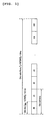
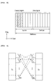
- FIG. 1 shows a structure of a type-1 radio frame.
- a type-1 radio frame consists of 10 subframes. Each of the frames consists of 2 slots.
- FIG. 2 shows a structure of a type-2 radio frame.
- a type-2 radio frame consists of 2 half frames.
- Each of the half frames consists of 5 subframes, a DwPTS (downlink pilot time slot), a guard period (GP), and a U P PTS (uplink pilot time slot).
- each of the subframes consists of 2 slots.
- the DwPTS is used for initial cell search, synchronization or channel estimation in a user equipment.
- the UpPTS is used for channel estimation and in matching uplink transmission synchronization of a user equipment.
- the guard period is a period for eliminating interference generated from uplink due to a multi-path delay of a downlink signal between uplink and downlink.
- 1 subframe consists of 2 slots.
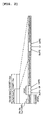
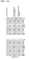
- FIG. 3 shows a structure of an LTE downlink slot.
- a signal transmitted in each slot can be represented as a resource grid consisting of N RB DL N sc RB subcarriers and N symb DL OFDM (orthogonal frequency division multiplexing) symbols.
- the N RB DL indicates the number of resource blocks (RBs) in downlink (DL)
- the N sc RB indicates the number of subcarriers constructing 1 RB
- FIG. 4 shows a structure of an LTE uplink slot.
- a signal transmitted in each slot can be represented as a resource grid consisting of N RB UL N SC RB subcarriers and N symb UL OFDM (orthogonal frequency division multiplexing) symbols.
- the N RB UL indicates the number of resource blocks (RBs) in uplink (UL)
- the N sc RB indicates the number of subcarriers constructing 1 RB
- the N symb UL indicates the number of OFDM symbols in one uplink slot.
- Resource element is a resource unit defined as indexes a and b within the UL/DL slot and indicates 1 subcarrier and 1 OFDM symbol.
- 'a' indicates an index on a frequency axis
- 'b' indicates an index on a time axis.
- FIG. 5 is a diagram for a structure of a DL subframe.
- maximum 3 OFDM symbols located in front part of a first slot within one subframe correspond to a control region allocated to a control channel.
- the rest of OFDM symbols correspond to a data region allocated to a physical downlink shared channel (PDSCH).
- PDSCH physical downlink shared channel
- downlink control channels used by 3GPP LTE include PCFICH (Physical Control Format Indicator Channel), PDCCH (Physical Downlink Control Channel), PHICH (Physical Hybrid ARQ Indicator Channel) and the like.
- MIMO is an abbreviation of multiple-input multiple-output and indicates a scheme of raising data transceiving efficiency by adopting multiple transmitting antennas and multiple receiving antennas instead of using a single transmitting antenna and a single receiving antenna conventionally.
- MIMO is the technology of increasing capacity or enhancing performance using the multiple antennas in a transmitter or receiver of a wireless communication system.
- the MIMO shall be named a multi-antenna.
- the multi-antenna technology applies a technique of completing a message by gathering data fragments received via several antennas together instead of depending on a single antenna path to receive the message. Since the multi-antenna technology enhances a data rate within a specific range or extends a system range for a specific data rate, it is the next generation mobile communication technology that is widely applicable to a mobile communication terminal, a relay and the like. Many attentions are paid to the multi-antenna technology as a next generation technology to overcome a throughput limit of mobile communication on the verge of a critical situation due to expansion of data communication and the like.
- FIG. 6 is a diagram for a configuration of a multi-antenna (MIMO) communication system.
- MIMO multi-antenna
- channel transmission capacity theoretically increases in proportion to the number of antennas unlike the case of using a plurality of antennas in a transmitter or receiver only. Hence, a transmission rate is raised and frequency efficiency can be dramatically enhanced.
- the transmission rate according to the increase of channel transmission capacity can be theoretically raised by an amount resulting from multiplying a maximum transmission rate R 0 in case of using a single antenna by an increase rate R i shown in Formula 1.
- fading occurs due to a multi-path time delay.
- a process for reconstructing a transmission signal by compensating signal distortion generated from abrupt environment change attributed to the fading is called channel estimation.
- the channel estimation is performed using a signal known to both a transmitting side and a receiving side.
- the signal known to both of the transmitting side and the receiving side is called a pilot signal or a reference signal (hereinafter abbreviated RS).
- reference signals are classified into a type of allocating reference signals to all subcarriers and a type of allocating reference signals between data subcarriers.
- a symbol including only reference signals such as a preamble signal is used. If a preamble signal is used, since density of reference signals is high, channel estimation performance can be improved better than that of the type of allocating reference signals between data subcarriers. Yet, since a transmission amount of data is reduced, the type of allocating the reference signals between the data subcarriers is used to increase the transmission amount of the data. If this type is used, the reference signal density is lowered. Therefore, the channel estimation performance is degraded. And, the demand for minimizing the degradation of the channel estimation performance is rising.
- a receiver performs channel estimation using a reference signal in the following manner. First of all, since a receiver is aware of information of a reference signal, channel information between the receiver and a transmitter is estimated from a received signal. The receiver is able to correctly demodulate data transmitted by the transmitter using the estimated channel information value.
- the receiver since the receiver is already aware of the reference signal p , it is able to estimate channel information ⁇ according to Formula 2.
- a structure of a radio frame applicable to FDD among the above described radio frame structures supported by 3GPP LTE is explained in detail as follows. First of all, 1 frame is transmitted in 10 msec. This frame consists of 10 subframes. And, one subframe is transmitted in 1 msec.
- One subframe consists of 14 or 12 OFDM (orthogonal frequency division multiplexing) symbols. And, the number of subcarriers in one OFDM symbol is set to one of 128, 26, 512, 1024, 1536 and 2048 to use.
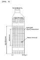
- FIG. 7 is a diagram of a structure of a UE-specific (user equipment-specific) DL reference signal in a subframe when 1 TTI (transmission time interval) uses a normal cyclic prefix (CP) having 14 OFDM symbols.
- TTI transmission time interval
- CP normal cyclic prefix
- 'R5' indicates a UE-specific reference signal and ' 1 ' indicates a position of an OFDM symbol in a subframe.
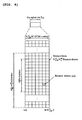
- FIG. 8 is a diagram of a structure of a UE-specific DL reference signal in a subframe when 1 TTI (transmission time interval) uses an extended cyclic prefix (CP) having 12 OFDM symbols.
- TTI transmission time interval
- CP extended cyclic prefix
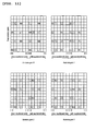
- FIGs. 9 to 11 are diagrams of structures of UE-common DL reference signals for systems having 1, 2 and 4 transmitting antennas, respectively, when 1 TTI has 14 OFDM symbols.
- R0 indicates a pilot symbol for a transmitting antenna
- R1 indicates a pilot symbol for a transmitting antenna 1
- R2 indicates a pilot symbol for a transmitting antenna 2
- R3 indicates a pilot symbol for a transmitting antenna 3.
- a signal is not carried on a subcarrier for which the pilot symbol of each of the transmitting antennas is used.
- FIG. 7 and FIG. 8 show the structures of the UE-specific DL reference signals, each of which can be simultaneously used together with the UE-common DL reference signal shown in FIGs. 9 to 11 .
- the UE-common DL reference signals shown in FIGs. 9 to 11 are used for the OFDM symbols 0 to 2 of a first slot in which control information is transmitted.
- the UE-specific DL reference signal is usable for the rest of the OFDM symbols.
- PN sequence is applied by an OFDM symbol unit within one subframe.
- the PN sequence is differently applicable according to a cell ID, a subframe index, an OFDM symbol position and a user equipment ID.
- pilot symbols of one transmitting antenna are used for a specific OFDM symbol including a pilot symbol.
- the types include 6 RBs (resource blocks) to 110 RBs.
- the number of pilot symbols of one transmitting antenna in one OFDM symbol including a pilot symbol is 2 ⁇ N RB .
- a sequence used by being multiplied by a downlink reference signal per cell should have a length of 2 ⁇ N RB .
- the N RB indicates the number of RBs according to a bandwidth.
- a binary sequence or a complex sequence may be used as a sequence.
- r(m) represents one example for a complex sequence.
- N RB max is the number of RBs corresponding to a maximum bandwidth and can be set to 110 according to the above description.
- 'c' indicates a PN sequence and can be defined as a Gold sequence of length-31.
- Formula 3 can be represented as Formula 4.
- N RB PDSCH indicates the number of RBs corresponding to DL data allocated to a specific user equipment. Therefore, a length of sequence can vary according to an amount allocated to a user equipment.
- the above described structure of the UE-specific DL reference signal can be transmitted as 1 data stream only. Since it is impossible to simply extend the structure, it is unable to transmit a plurality of streams. Therefore, the structure of the UE-specific DL reference signal needs to be extended to transmit a plurality of data streams.
- the necessity of user equipment positioning is ongoing to rise according to various operations due to diverse application in real life environments.
- the user equipment positioning can be mainly classified into a GPS (global positioning system) based method and a terrestrial positioning based method.
- the GPS based method measures a location of a user equipment using satellites.
- the GPS based method needs signals from at least 4 satellites. And, it is disadvantageous in that the GPS based method is not available for an indoor environment.
- the terrestrial positioning based method measures a location of a user equipment using a timing difference between signals from base stations.
- the terrestrial positioning based method needs signals received from at least 3 base stations.
- the terrestrial positioning based method has positioning estimation performance poorer than that of the GPS based method but is available for almost every environment.
- the terrestrial positioning based method estimates a location of a user equipment using a synchronization signal or a reference signal generally.
- the terrestrial positioning based method is defined as the following terminology per standard.
- the terrestrial positioning based method is defined as OTDOA (Observed Time Difference of Arrival).
- OTDOA Observed Time Difference of Arrival
- GERAN GSM/EDGE Radio Access Network
- E-OTD Enhanced Observed Time Difference
- AFLT Advanced Forward Link Trilateration
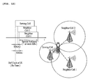
- FIG. 12 is a diagram of an example for downlink OTDOA as a sort of a terrestrial positioning based method used by the 3GPP standard.
- FIG. 13 is a diagram of an example for a user equipment positioning method using OTDOA.
- a location of a user equipment can be calculated by solving a linear equation using Taylor series expansion (cf. Y. Chan and K. Ho, "A simple and efficient estimator for hyperbolic location," IEEE Trans. Signal Processing, vol. 42, pp. 1905-1915, Aug. 1994 ).
- the above mentioned user equipment positioning method can be normally performed via Common Reference Signal (CRS) or Primary Synchronization Signal/Secondary Synchronization Signal (PSS/SSS).
- CRS Common Reference Signal
- PSS/SSS Primary Synchronization Signal/Secondary Synchronization Signal
- the user equipment positioning method can be performed in a manner of defining Positioning Reference Signal (PRS) dedicated to LCS (Location Service).
- PRS Positioning Reference Signal
- the positioning subframe can be defined through scheduling in normal subframe or by configuring MBSFN subframe (e.g., periodicity of 80ms or 320ms).
- Es/It is increased by extending inter-cell reuse through the above method, whereby measurement of a neighbor cell is enabled.
- the 'Es' indicates signal energy of a specific signal.
- the 'It' indicates power spectral density of an interference signal and is generally called SINR.
- multiple subframe averaging should be performed.
- periodicity of a positioning subframe needs to be appropriately set. For instance, if a periodicity of a reference signal (RS) sequence is defined as 10ms and a periodicity of a positioning subframe is 80ms, effect of interference averaging does not exist.
- RS reference signal
- the present invention is directed to an apparatus for positioning a user equipment and method thereof that substantially obviate one or more problems due to limitations and disadvantages of the related art.
- An object of the present invention is to provide an apparatus for positioning a user equipment and method thereof, by which interference averaging effect can be obtained in a manner of setting a generation periodicity of a reference signal and a periodicity of a positioning subframe.
- a method of positioning a user equipment in a wireless communication system includes the steps of receiving a user equipment positioning subframe including a reference signal by a prescribed periodicity from a base station and measuring a TOA (timing of arrival) of the subframe using the reference signal included in the received subframe, wherein the prescribed periodicity is set in a manner that a sequence of the reference signal included in the user equipment positioning subframe is changed per the prescribed periodicity.
- the prescribed periodicity can be set disjoint with a generation periodicity of a sequence of the reference signal.
- the prescribed periodicity can be set smaller than a generation periodicity of a sequence of the reference signal.
- the prescribed periodicity can be set to a value greater than a generation periodicity of a sequence of the reference signal and smaller than a twice of the generation periodicity of the reference signal.
- the reference signal can include a common reference signal or a positioning reference signal.
- the method further includes the step of receiving information on the prescribed periodicity via RRC (radio resource control).
- RRC radio resource control
- a user equipment in a wireless communication system includes a receiving unit configured to receive a user equipment positioning subframe including a reference signal by a prescribed periodicity from a base station and a processing unit electrically connected to the receiving unit, the processing unit configured to position a location of the user equipment using the reference signal included in the received user equipment positioning subframe, wherein the prescribed periodicity is set in a manner that a sequence of the reference signal included in the user equipment positioning subframe is changed per the prescribed periodicity.
- the prescribed periodicity can be set disjoint with a generation periodicity of a sequence of the reference signal.
- the prescribed periodicity can be set smaller than a generation periodicity of a sequence of the reference signal.
- the prescribed periodicity can be set to a value greater than a generation periodicity of a sequence of the reference signal and smaller than a twice of the generation periodicity of the reference signal.
- the reference signal can include a common reference signal or a positioning reference signal.
- the receiving unit can receive information on the prescribed periodicity.
- the receiving unit can receive information on the prescribed periodicity via RRC (radio resource control).
- RRC radio resource control
- a method for positioning a user equipment in wireless communication system includes receiving, from a plurality of base stations including a serving cell, a predetermined number of consecutive positioning subframes in a radio frame at a predetermined period, each of the consecutive positioning subframes including a reference signal, measuring a time of arrival of the positioning subframes by using the reference signal, and transmitting a result of the measured time of arrival of the positioning subframe to the serving cell, wherein the predetermined period is set to be larger than a generation period of the reference signal and wherein a sequence of the reference signal included in each of the consecutive positioning subframes is different from each other.
- the reference signal is one of a common reference signal and a positioning reference signal.
- the method further includes receiving information on the predetermined period via Radio Resource Control (RRC).
- RRC Radio Resource Control
- the predetermined number of the consecutive positioning subframes is one of 2, 3 and 4.
- a user equipment in a wireless communication system includes a receiving unit for receiving, from a plurality of base stations including a serving cell, a predetermined number of consecutive positioning subframes in a radio frame at a predetermined period, each of the consecutive positioning subframes including reference signal, a processing unit for measuring a time of arrival of the positioning subframes by using the reference signal, and a transmitting unit for transmitting a result of the measured time of arrival of the positioning subframe to the serving cell, wherein the predetermined period is set to be larger than a generation period of the reference signal and wherein a sequence of the reference signal included in each of the consecutive positioning subframes is different from each other.
- the reference signal is one of a common reference signal and positioning reference signal.
- the receiving unit receives information on the predetermined period via Radio Resource Control (RRC).
- RRC Radio Resource Control
- the predetermined number of the consecutive positioning subframes is one of 2, 3 and 4.
- FIG. 1 shows a structure of a type-1 radio frame
- FIG. 2 shows a structure of a type-2 radio frame
- FIG. 3 shows a structure of an LTE downlink slot
- FIG. 4 shows a structure of an LTE uplink slot
- FIG. 5 is a diagram for a structure of a DL subframe
- FIG. 6 is a diagram for a configuration of a multi-antenna (MIMO) communication system
- FIG. 7 is a diagram of a structure of a UE-specific DL reference signal in a subframe when 1 TTI (transmission time interval) uses a normal cyclic prefix (CP) having 14 OFDM symbols;
- TTI transmission time interval
- CP normal cyclic prefix
- FIG. 8 is a diagram of a structure of a UE-specific DL reference signal in a subframe when 1 TTI (transmission time interval) uses an extended cyclic prefix (CP) having 12 OFDM symbols;
- TTI transmission time interval
- CP extended cyclic prefix
- FIGs. 9 to 11 are diagrams of structures of UE-common DL reference signals for systems having 1, 2 and 4 transmitting antennas, respectively, when 1 TTI has 14 OFDM symbols;
- FIG. 12 is a diagram of an example for downlink OTDOA as a sort of a terrestrial positioning based method used by the 3GPP standard;
- FIG. 13 is a diagram of an example for a user equipment positioning method using OTDOA
- FIG. 14 is a diagram for a relation between a sequence periodicity of a reference signal and a periodicity of a positioning subframe
- FIG. 15 is a diagram of an example for periodic transmission of a positioning subframe without interference diversity
- FIG. 16 is a diagram for a case of setting a periodicity of a positioning subframe for an interference diversity gain according to one embodiment of the present invention.
- FIG. 17 is a block diagram for a configuration of a device applicable to a base station and a user equipment to perform the above described method.
- a prescribed part includes' a prescribed element, it means that another element can be further included instead of eliminating other elements as long as absence of special objection.
- a terminology as ' ⁇ part' ' ⁇ functionality', ' ⁇ module' and the like means a unit for handling at least one function or operation, which can be implemented by software, hardware or combination thereof.
- a terrestrial positioning based method as a user equipment positioning method.
- This method can be normally performed via Common Reference Signal (CRS) or Primary Synchronization Signal/Secondary Synchronization Signal (PSS/SSS).
- CRS Common Reference Signal
- PSS/SSS Primary Synchronization Signal/Secondary Synchronization Signal
- this method can define to use a Positioning Reference Signal (PRS) dedicated to LCS (Location Service).
- PRS Positioning Reference Signal
- a positioning subframe for LCS By defining a positioning subframe for LCS, data scheduling is not performed on a corresponding positioning subframe and a reference signal can be transmitted only.
- a reference signal sequence r i,n s ( m ) for positioning can be defined as Formula 5.
- n s indicates a slot number within one radio frame and 1 indicates an OFDM symbol number within a corresponding slot.
- c(i) indicates a pseudo-random sequence.
- a pseudo-random sequence generator is defined at a start of each OFDM symbol by Formula 6.
- N cp meets Formula 7.
- N CP ⁇ 1 for normal CP 0 for extended CP
- a periodicity of a reference signal sequence is 10 ms.
- a periodicity of a positioning subframe is 80 ms.
- the same reference signal sequence is repeated each periodicity of the reference signal sequence.
- a positioning subframe used in determining a location of a user equipment is transmitted each positioning subframe periodicity.
- FIG. 14 is a diagram for a relation between a sequence periodicity of a reference signal and a periodicity of a positioning subframe.
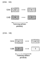
- FIG. 15 is a diagram of an example for periodic transmission of a positioning subframe without interference diversity.
- a periodicity of a reference signal sequence is 10 ms (i.e., a generation periodicity of a common reference signal (CRS) is 10 subframes, i.e., 10 ms.)
- a reference signal sequence repeated every 80ms is always the same sequence.
- a positioning subframe colliding every periodicity of the positioning subframe of the cell A is always a subframe-a and a positioning subframe colliding every periodicity of the positioning subframe of the cell B is always a subframe-b, as shown in FIG. 15 .
- the meaning of the same subframe every positioning subframe periodicity indicates that a reference signal sequence transmitted via a subframe each periodicity of a positioning subframe is always the same. Since a positioning subframe colliding every periodicity of the positioning subframe does not change, even if interference between two subframes is infinitely averaged, SIR (signal to interference ratio) is not improved. Therefore, when interference averaging is performed in a positioning subframe, an interference diversity gain may not be obtained. In particular, since a reference signal sequence transmitted in a positioning subframe of a serving cell is a periodically identical sequence and a corresponding reference signal sequence of a neighbor cell is always the same sequence, when a user equipment performs interference averaging on a plurality of positioning subframes, SIR does not change. Therefore, it is requested that a sequence of a reference signal transmitted via a positioning subframe should not be set identical per periodicity.
- FIG. 16 is a diagram for a case of setting a periodicity of a positioning subframe for an interference diversity gain according to one embodiment of the present invention.
- the present invention proposes that a transmission periodicity of a positioning subframe including a positioning RS shall be set by one of the following methods.
- a reference signal generation periodicity and a positioning subframe periodicity are set to establish a disjoint relation in-between. For instance, when a periodicity of a reference signal sequence is 10 ms, a periodicity of a positioning subframe is set to 31 ms that is disjoint with 10.
- a reference signal sequence of two cells colliding with each other at 31 ms and a reference signal sequence of two cells colliding with each other at 31*2 ms have a generation periodicity of a reference signal sequence is 10 ms, the reference signal sequence of two cells colliding with each other at 31 ms is different from the reference signal sequence of two cells colliding with each other at 31*2 ms. Therefore, it is able to obtain an interference diversity gain.
- a periodicity of a positioning subframe is set smaller than a reference signal generation periodicity. For instance, when a generation periodicity of a reference signal sequence is 10 ms, it is able to set a periodicity of a positioning subframe to 2 ms. Alternatively, when a generation periodicity of a reference signal sequence is 40 ms, it is able to set a periodicity of a positioning subframe to 10 ms. Alternatively, when a generation periodicity of a reference signal sequence is 10 ms, it is able to set a periodicity of a positioning subframe to 1 ms. In this case, if a length of the positioning subframe is equal to a periodicity of the positioning subframe, consecutive positioning subframes can be transmitted.
- a periodicity of a positioning subframe is set to obtain at least two interference randomization gains in consideration of multiple subframe averaging.
- a periodicity of a positioning subframe can be set to a value greater than a generation periodicity of a reference signal sequence and smaller than a twice of the generation periodicity of the reference signal sequence. For instance, when a generation periodicity of a reference signal sequence is 10 ms, it is able to set a periodicity of a positioning subframe to 12 ms. In this case, the positioning subframe is set to be transmitted every 12 ms, 24 ms and 36 ms.
- a generation periodicity of a reference signal sequence is 10 ms
- a positioning subframe transmitted by a prescribed periodicity can include a prescribed number of consecutive positioning subframes.
- the prescribed number can include 2, 3 or 4.
- This periodicity of a positioning subframe is predefined or can be notified to a user equipment via higher layer signaling, e.g., RRC signaling.
- a reference signal transmitted in a positioning subframe is applicable irrespective of a type (e.g., CRS, PRS, etc.) of the reference signal.
- FIG. 17 is a block diagram for a configuration of a device applicable to a base station and a user equipment to perform the above described method.
- a device 100 includes a processing unit 101, a memory unit 102, an RF (radio frequency) unit 103, a display unit 104 and a user interface unit 105.
- a layer of a physical interface protocol is performed by the processing unit 101.
- the processing unit 101 provides a control plane and a user plane. A function of each layer can be performed by the processing unit 101.
- the processing unit 101 can perform the above mentioned embodiments of the present invention.
- the processing unit 101 is able to perform a function of generating a subframe for user equipment positioning or a function of receiving a subframe and then positioning a location of a user equipment.
- the memory unit 102 is electrically connected to the processing unit 101.
- the display unit 104 is able to display various kinds of informations. And, the display unit 104 can be implemented using a well-known LCD (liquid crystal display), an OLED (organic light emitting diode) display and the like.
- the user interface unit 105 can be configured by being combined with such a well-known user interface as a keypad, a touchscreen and the like.
- the RF unit 103 is electrically connected to the processing unit 101. The RF unit 103 transmits or receives a radio signal.
- 'user equipment (UE)' can be replaced by such a terminology as a mobile station (MS), a subscriber station (SS), a mobile subscriber station (MSS), a mobile terminal and the like.
- MS mobile station
- SS subscriber station
- MSS mobile subscriber station
- a user equipment of the present invention can include one of a PDA (Personal Digital Assistant), a cellular phone, a PCS (Personal Communication Service) phone, a GSM (Global System for Mobile) phone, a WCDMA (Wideband CDMA) phone, an MBS (Mobile Broadband System) phone and the like.
- PDA Personal Digital Assistant
- a cellular phone a PCS (Personal Communication Service) phone
- GSM Global System for Mobile
- WCDMA Wideband CDMA
- MBS Mobile Broadband System
- Embodiments of the present invention can be implemented using various means. For instance, embodiments of the present invention can be implemented using hardware, firmware, software and/or any combinations thereof.
- a method according to each embodiment of the present invention can be implemented by at least one selected from the group consisting of ASICs (application specific integrated circuits), DSPs (digital signal processors), DSPDs (digital signal processing devices), PLDs (programmable logic devices), FPGAs (field programmable gate arrays), processor, controller, microcontroller, microprocessor and the like.
- ASICs application specific integrated circuits
- DSPs digital signal processors
- DSPDs digital signal processing devices
- PLDs programmable logic devices
- FPGAs field programmable gate arrays
- processor controller, microcontroller, microprocessor and the like.
- a method according to each embodiment of the present invention can be implemented by modules, procedures, and/or functions for performing the above-explained functions or operations.
- Software code is stored in a memory unit and is then drivable by a processor.
- the memory unit is provided within or outside the processor to exchange data with the processor through the various well-known means.
- the present invention is applicable to a user equipment, a base station and other equipments in a wireless mobile communication system.
Landscapes
- Engineering & Computer Science (AREA)
- Physics & Mathematics (AREA)
- General Physics & Mathematics (AREA)
- Radar, Positioning & Navigation (AREA)
- Remote Sensing (AREA)
- Computer Networks & Wireless Communication (AREA)
- Signal Processing (AREA)
- Mobile Radio Communication Systems (AREA)
- Position Fixing By Use Of Radio Waves (AREA)
Applications Claiming Priority (3)
| Application Number | Priority Date | Filing Date | Title |
|---|---|---|---|
| US17576909P | 2009-05-05 | 2009-05-05 | |
| KR1020100009452A KR101703860B1 (ko) | 2009-05-05 | 2010-02-02 | 무선 이동 통신 시스템에 있어서, 사용자 기기의 위치를 결정하기 위한 방법 및 이를 수행하기 위한 장치 |
| PCT/KR2010/002764 WO2010128774A2 (ko) | 2009-05-05 | 2010-04-30 | 무선 이동 통신 시스템에 있어서, 사용자 기기의 위치를 결정하기 위한 방법 및 이를 수행하기 위한 장치 |
Publications (2)
| Publication Number | Publication Date |
|---|---|
| EP2428811A2 true EP2428811A2 (de) | 2012-03-14 |
| EP2428811A4 EP2428811A4 (de) | 2015-01-14 |
Family
ID=43405886
Family Applications (1)
| Application Number | Title | Priority Date | Filing Date |
|---|---|---|---|
| EP10772234.0A Ceased EP2428811A4 (de) | 2009-05-05 | 2010-04-30 | Verfahren zur positionierung eines benutzergeräts in einem drahtlosen mobilen kommunikationssystem und vorrichtung zur durchführung des verfahrens |
Country Status (5)
| Country | Link |
|---|---|
| US (1) | US8964579B2 (de) |
| EP (1) | EP2428811A4 (de) |
| KR (1) | KR101703860B1 (de) |
| CN (2) | CN103760523B (de) |
| WO (1) | WO2010128774A2 (de) |
Families Citing this family (12)
| Publication number | Priority date | Publication date | Assignee | Title |
|---|---|---|---|---|
| US8614975B2 (en) | 2008-09-19 | 2013-12-24 | Qualcomm Incorporated | Synchronizing a base station in a wireless communication system |
| US9037155B2 (en) * | 2008-10-28 | 2015-05-19 | Sven Fischer | Time of arrival (TOA) estimation for positioning in a wireless communication network |
| US8982851B2 (en) | 2009-01-06 | 2015-03-17 | Qualcomm Incorporated | Hearability improvements for reference signals |
| WO2010126842A1 (en) * | 2009-04-27 | 2010-11-04 | Interdigital Patent Holdings, Inc. | Reference signals for positioning measurements |
| US8688139B2 (en) | 2009-09-10 | 2014-04-01 | Qualcomm Incorporated | Concurrent wireless transmitter mapping and mobile station positioning |
| US9091746B2 (en) | 2010-07-01 | 2015-07-28 | Qualcomm Incorporated | Determination of positions of wireless transceivers to be added to a wireless communication network |
| WO2013133673A1 (ko) | 2012-03-08 | 2013-09-12 | 엘지전자 주식회사 | 참조 신호 수신 방법 및 사용자기기와, 참조 신호 전송 방법 및 기지국 |
| WO2016155774A1 (en) * | 2015-03-30 | 2016-10-06 | Sony Corporation | Apparatus, systems and methods for mobile network positioning of mtc devices using common reference or synchronization signals |
| US10749778B2 (en) * | 2015-07-28 | 2020-08-18 | Acorn Technologies, Inc. | Communication system determining time of arrival using matching pursuit |
| US11122535B2 (en) * | 2016-07-15 | 2021-09-14 | Qualcomm Incorporated | Techniques for locating devices using narrowband positioning reference signals |
| JP6949939B2 (ja) * | 2016-08-11 | 2021-10-13 | ソニーモバイルコミュニケーションズ株式会社 | モバイルデバイスのtdoa測位 |
| WO2020090241A1 (ja) * | 2018-11-01 | 2020-05-07 | ソニー株式会社 | 通信装置及び通信方法 |
Family Cites Families (18)
| Publication number | Priority date | Publication date | Assignee | Title |
|---|---|---|---|---|
| US5600706A (en) * | 1992-04-08 | 1997-02-04 | U S West, Inc. | Method and system for determining the position of a mobile receiver |
| DE69634845T2 (de) * | 1995-01-05 | 2006-05-18 | Ntt Docomo Inc. | Vorrichtung und verfahren zur kohärenten verfolgung eines signals zur verwendung in einem cdma empfänger |
| CN1158890C (zh) | 1997-08-18 | 2004-07-21 | 艾利森电话股份有限公司 | 用于确定移动无线终端位置的方法和系统 |
| GB9912724D0 (en) | 1999-06-01 | 1999-08-04 | Cambridge Positioning Sys Ltd | Radio positioning system |
| CA2440750C (en) | 2001-03-15 | 2011-04-26 | Qualcomm Incorporated | Time acquisition in a wireless position determination system |
| KR100834634B1 (ko) * | 2001-08-27 | 2008-06-02 | 삼성전자주식회사 | 이동 통신 시스템에서 단말기의 위치 추정 장치 및 방법 |
| JP4093792B2 (ja) | 2002-04-18 | 2008-06-04 | 富士通株式会社 | 移動無線局の位置を決定する測位システム、プログラムおよび位置決定方法 |
| KR100594101B1 (ko) * | 2003-01-20 | 2006-06-30 | 삼성전자주식회사 | 비추적 영역에서 멀티캐스트 멀티미디어 방송 서비스를제공하는 시스템 및 방법 |
| CA2744847C (en) | 2005-11-07 | 2013-09-10 | Qualcomm Incorporated | Positioning for wlans and other wireless networks |
| EP2104254A4 (de) * | 2007-01-09 | 2012-04-11 | Ntt Docomo Inc | Basisstationseinrichtung und kommunikationssteuerverfahren |
| WO2008114181A1 (en) | 2007-03-20 | 2008-09-25 | Nokia Corporation | Method, apparatus and computer program product for adaptive reference symbol placement |
| US7808882B2 (en) * | 2007-04-17 | 2010-10-05 | Sharp Laboratories Of America, Inc. | Method and system for optimized reference signal downlink transmission in a wireless communication system |
| CN101339238B (zh) * | 2007-07-06 | 2011-08-24 | 展讯通信(上海)有限公司 | 基于多系统联合测量的无线定位的位置计算方法与装置 |
| US8289946B2 (en) * | 2007-08-14 | 2012-10-16 | Qualcomm Incorporated | Reference signal generation in a wireless communication system |
| CN101384070A (zh) * | 2007-09-06 | 2009-03-11 | 大唐移动通信设备有限公司 | 一种移动终端定位方法、装置及系统 |
| US7940740B2 (en) * | 2009-02-03 | 2011-05-10 | Motorola Mobility, Inc. | Apparatus and method for communicating and processing a positioning reference signal based on identifier associated with a base station |
| ES2401954T3 (es) * | 2009-03-10 | 2013-04-25 | Telefonaktiebolaget Lm Ericsson (Publ) | Método y disposición para posicionamiento por DL-OTDOA (diferencia de tiempo de llegada observada en enlace descendente) en un sistema de comunicaciones inalámbricas de LTE (evolución de largo plazo) |
| WO2010126842A1 (en) * | 2009-04-27 | 2010-11-04 | Interdigital Patent Holdings, Inc. | Reference signals for positioning measurements |
-
2010
- 2010-02-02 KR KR1020100009452A patent/KR101703860B1/ko active Active
- 2010-04-30 US US13/318,773 patent/US8964579B2/en active Active
- 2010-04-30 WO PCT/KR2010/002764 patent/WO2010128774A2/ko not_active Ceased
- 2010-04-30 EP EP10772234.0A patent/EP2428811A4/de not_active Ceased
- 2010-04-30 CN CN201410024845.4A patent/CN103760523B/zh active Active
- 2010-04-30 CN CN201080019878.XA patent/CN102422175B/zh not_active Expired - Fee Related
Also Published As
| Publication number | Publication date |
|---|---|
| KR20100120260A (ko) | 2010-11-15 |
| WO2010128774A2 (ko) | 2010-11-11 |
| CN103760523B (zh) | 2016-08-17 |
| CN102422175B (zh) | 2014-02-26 |
| US20120057498A1 (en) | 2012-03-08 |
| CN102422175A (zh) | 2012-04-18 |
| KR101703860B1 (ko) | 2017-02-22 |
| WO2010128774A3 (ko) | 2011-02-17 |
| CN103760523A (zh) | 2014-04-30 |
| EP2428811A4 (de) | 2015-01-14 |
| US8964579B2 (en) | 2015-02-24 |
Similar Documents
| Publication | Publication Date | Title |
|---|---|---|
| US8964579B2 (en) | Method for positioning user equipment in a wireless mobile communication system, and apparatus for performing the method | |
| US10004057B2 (en) | Method for performing OTDOA-related operation in wireless communication system | |
| US9544725B2 (en) | Method for determining position of user equipment and apparatus for performing same in wireless mobile communication system | |
| CN111295914B (zh) | 在支持侧链路的无线通信系统中由终端发送定位信息的方法及其设备 | |
| EP3402100B1 (de) | Verfahren zum senden und empfangen von signalen zwischen einem endgerät und einer basisstation in einem drahtloskommunikationssystem und vorrichtung zur unterstützung davon | |
| US9736629B2 (en) | Method and apparatus for transmitting location estimation message in wireless communication system | |
| US8982788B2 (en) | Method and apparatus for transmitting positioning reference signal in wireless communication system | |
| US8842639B2 (en) | Method for pilot symbol transmission in downlink MIMO system | |
| US9313765B2 (en) | Method for measuring position in wireless communication system | |
| EP2941041B1 (de) | Verfahren zum senden und empfangen von kanalqualitätsindikatorinformationen in einem drahtlosen zugriffssystem und vorrichtung zur unterstützung davon | |
| EP3496476A1 (de) | Verfahren und drahtlose vorrichtung zur durchführung einer positionsmessung in nb iot | |
| US10935629B2 (en) | Method for performing OTDOA-related operations in wireless communication system | |
| EP2395677A2 (de) | Verfahren zur übertragung eines allgemeinen referenzsignals in einem downlink-mimo-system | |
| KR20110019693A (ko) | 무선 이동통신 시스템에 있어서, 사용자 기기의 위치 추정을 위한 신호를 전송하는 방법 및 장치 | |
| KR20100110733A (ko) | 무선 이동 통신 시스템에 있어서, 사용자 기기의 위치를 결정하기 위한 방법 및 이를 수행하기 위한 장치 |
Legal Events
| Date | Code | Title | Description |
|---|---|---|---|
| PUAI | Public reference made under article 153(3) epc to a published international application that has entered the european phase |
Free format text: ORIGINAL CODE: 0009012 |
|
| 17P | Request for examination filed |
Effective date: 20111107 |
|
| AK | Designated contracting states |
Kind code of ref document: A2 Designated state(s): AT BE BG CH CY CZ DE DK EE ES FI FR GB GR HR HU IE IS IT LI LT LU LV MC MK MT NL NO PL PT RO SE SI SK SM TR |
|
| DAX | Request for extension of the european patent (deleted) | ||
| A4 | Supplementary search report drawn up and despatched |
Effective date: 20141211 |
|
| RIC1 | Information provided on ipc code assigned before grant |
Ipc: G01S 5/10 20060101ALI20141205BHEP Ipc: G01S 5/00 20060101AFI20141205BHEP |
|
| STAA | Information on the status of an ep patent application or granted ep patent |
Free format text: STATUS: EXAMINATION IS IN PROGRESS |
|
| 17Q | First examination report despatched |
Effective date: 20170406 |
|
| REG | Reference to a national code |
Ref country code: DE Ref legal event code: R003 |
|
| STAA | Information on the status of an ep patent application or granted ep patent |
Free format text: STATUS: THE APPLICATION HAS BEEN REFUSED |
|
| 18R | Application refused |
Effective date: 20230716 |