EP2428809A2 - Battery controller and voltage abnormality detection method - Google Patents
Battery controller and voltage abnormality detection method Download PDFInfo
- Publication number
- EP2428809A2 EP2428809A2 EP11177333A EP11177333A EP2428809A2 EP 2428809 A2 EP2428809 A2 EP 2428809A2 EP 11177333 A EP11177333 A EP 11177333A EP 11177333 A EP11177333 A EP 11177333A EP 2428809 A2 EP2428809 A2 EP 2428809A2
- Authority
- EP
- European Patent Office
- Prior art keywords
- battery
- voltage
- reference value
- value
- unit
- Prior art date
- Legal status (The legal status is an assumption and is not a legal conclusion. Google has not performed a legal analysis and makes no representation as to the accuracy of the status listed.)
- Withdrawn
Links
Images


Classifications
-
- G—PHYSICS
- G01—MEASURING; TESTING
- G01R—MEASURING ELECTRIC VARIABLES; MEASURING MAGNETIC VARIABLES
- G01R31/00—Arrangements for testing electric properties; Arrangements for locating electric faults; Arrangements for electrical testing characterised by what is being tested not provided for elsewhere
- G01R31/36—Arrangements for testing, measuring or monitoring the electrical condition of accumulators or electric batteries, e.g. capacity or state of charge [SoC]
- G01R31/392—Determining battery ageing or deterioration, e.g. state of health
-
- G—PHYSICS
- G01—MEASURING; TESTING
- G01R—MEASURING ELECTRIC VARIABLES; MEASURING MAGNETIC VARIABLES
- G01R19/00—Arrangements for measuring currents or voltages or for indicating presence or sign thereof
- G01R19/165—Indicating that current or voltage is either above or below a predetermined value or within or outside a predetermined range of values
- G01R19/16533—Indicating that current or voltage is either above or below a predetermined value or within or outside a predetermined range of values characterised by the application
- G01R19/16538—Indicating that current or voltage is either above or below a predetermined value or within or outside a predetermined range of values characterised by the application in AC or DC supplies
- G01R19/16542—Indicating that current or voltage is either above or below a predetermined value or within or outside a predetermined range of values characterised by the application in AC or DC supplies for batteries
-
- B—PERFORMING OPERATIONS; TRANSPORTING
- B60—VEHICLES IN GENERAL
- B60R—VEHICLES, VEHICLE FITTINGS, OR VEHICLE PARTS, NOT OTHERWISE PROVIDED FOR
- B60R16/00—Electric or fluid circuits specially adapted for vehicles and not otherwise provided for; Arrangement of elements of electric or fluid circuits specially adapted for vehicles and not otherwise provided for
- B60R16/02—Electric or fluid circuits specially adapted for vehicles and not otherwise provided for; Arrangement of elements of electric or fluid circuits specially adapted for vehicles and not otherwise provided for electric constitutive elements
- B60R16/03—Electric or fluid circuits specially adapted for vehicles and not otherwise provided for; Arrangement of elements of electric or fluid circuits specially adapted for vehicles and not otherwise provided for electric constitutive elements for supply of electrical power to vehicle subsystems or for
- B60R16/033—Electric or fluid circuits specially adapted for vehicles and not otherwise provided for; Arrangement of elements of electric or fluid circuits specially adapted for vehicles and not otherwise provided for electric constitutive elements for supply of electrical power to vehicle subsystems or for characterised by the use of electrical cells or batteries
-
- G—PHYSICS
- G01—MEASURING; TESTING
- G01R—MEASURING ELECTRIC VARIABLES; MEASURING MAGNETIC VARIABLES
- G01R19/00—Arrangements for measuring currents or voltages or for indicating presence or sign thereof
- G01R19/003—Measuring mean values of current or voltage during a given time interval
-
- G—PHYSICS
- G01—MEASURING; TESTING
- G01R—MEASURING ELECTRIC VARIABLES; MEASURING MAGNETIC VARIABLES
- G01R19/00—Arrangements for measuring currents or voltages or for indicating presence or sign thereof
- G01R19/30—Measuring the maximum or the minimum value of current or voltage reached in a time interval
-
- G—PHYSICS
- G01—MEASURING; TESTING
- G01R—MEASURING ELECTRIC VARIABLES; MEASURING MAGNETIC VARIABLES
- G01R31/00—Arrangements for testing electric properties; Arrangements for locating electric faults; Arrangements for electrical testing characterised by what is being tested not provided for elsewhere
- G01R31/36—Arrangements for testing, measuring or monitoring the electrical condition of accumulators or electric batteries, e.g. capacity or state of charge [SoC]
- G01R31/382—Arrangements for monitoring battery or accumulator variables, e.g. SoC
- G01R31/3835—Arrangements for monitoring battery or accumulator variables, e.g. SoC involving only voltage measurements
-
- G—PHYSICS
- G01—MEASURING; TESTING
- G01R—MEASURING ELECTRIC VARIABLES; MEASURING MAGNETIC VARIABLES
- G01R31/00—Arrangements for testing electric properties; Arrangements for locating electric faults; Arrangements for electrical testing characterised by what is being tested not provided for elsewhere
- G01R31/36—Arrangements for testing, measuring or monitoring the electrical condition of accumulators or electric batteries, e.g. capacity or state of charge [SoC]
- G01R31/396—Acquisition or processing of data for testing or for monitoring individual cells or groups of cells within a battery
-
- G—PHYSICS
- G01—MEASURING; TESTING
- G01R—MEASURING ELECTRIC VARIABLES; MEASURING MAGNETIC VARIABLES
- G01R35/00—Testing or calibrating of apparatus covered by the other groups of this subclass
-
- H—ELECTRICITY
- H01—ELECTRIC ELEMENTS
- H01M—PROCESSES OR MEANS, e.g. BATTERIES, FOR THE DIRECT CONVERSION OF CHEMICAL ENERGY INTO ELECTRICAL ENERGY
- H01M10/00—Secondary cells; Manufacture thereof
- H01M10/42—Methods or arrangements for servicing or maintenance of secondary cells or secondary half-cells
- H01M10/48—Accumulators combined with arrangements for measuring, testing or indicating the condition of cells, e.g. the level or density of the electrolyte
-
- Y—GENERAL TAGGING OF NEW TECHNOLOGICAL DEVELOPMENTS; GENERAL TAGGING OF CROSS-SECTIONAL TECHNOLOGIES SPANNING OVER SEVERAL SECTIONS OF THE IPC; TECHNICAL SUBJECTS COVERED BY FORMER USPC CROSS-REFERENCE ART COLLECTIONS [XRACs] AND DIGESTS
- Y02—TECHNOLOGIES OR APPLICATIONS FOR MITIGATION OR ADAPTATION AGAINST CLIMATE CHANGE
- Y02E—REDUCTION OF GREENHOUSE GAS [GHG] EMISSIONS, RELATED TO ENERGY GENERATION, TRANSMISSION OR DISTRIBUTION
- Y02E60/00—Enabling technologies; Technologies with a potential or indirect contribution to GHG emissions mitigation
- Y02E60/10—Energy storage using batteries
Definitions
- the present invention relates to a battery module configured by connecting a plurality of secondary batteries to be mounted on a vehicle or the like.
- the secondary battery Since a vehicular secondary battery carries a large amount of electric current, a micro-short circuit due to the mixing of foreign matter incurs reliability degradation or an increase in time degradation.
- the secondary battery has a structure in which a separator serving as an insulator is included between a positive electrode and a negative electrode. If any electrically-conductive foreign matter (for example, a metal piece) gets mixed between one of these electrodes and the separator, the positive and negative electrodes suffer a micro-short circuit, thus causing an abnormal voltage drop in the secondary battery.
- an average voltage value of secondary batteries in the specific module is used as a common reference value among a plurality of modules.
- a voltage measuring unit cell controller IC
- a battery controller for controlling an assembled battery configured by connecting a plurality of battery groups each including a plurality of battery cells, comprises: a plurality of voltage measuring units that are provided respectively for the plurality of battery groups each to measure a voltage of each of the battery cells included in a corresponding battery group; a minimum value detecting unit that detects a minimum value of the battery cells for each of the plurality of battery groups based upon the voltage of each of the battery cells measured by a corresponding voltage measuring unit; a reference value setting unit that sets a reference value used to determine an abnormal voltage drop for each of the plurality of battery groups based upon the voltage of each of the battery cells measured by the corresponding voltage measuring unit; and/or an abnormality determining unit that makes a determination that an abnormal voltage drop is present, if a difference between the reference value and the minimum value exceeds a predetermined value, for each of the plurality of battery groups.
- the reference value setting unit sets a maximum voltage of the battery cells within a battery group as the reference value.
- the reference value setting unit sets an average voltage value of battery cells except a battery cell having a minimum voltage, within a battery group as the reference value.
- the reference value setting unit sets a median voltage value of battery cells except a battery cell having a minimum voltage, within a battery group as the reference value.
- the battery controller further comprises: a temperature measuring unit that measures a temperature of each of the plurality of voltage measuring units; and a reference value changing unit that changes the reference value based upon the temperature measured by the temperature measuring unit.
- the battery controller further comprises: a stop time measuring unit that measures a time during which a vehicle mounted with the assembled battery is stopped; and a reference value changing unit that changes the reference value based upon the stop time measured by the stop time measuring unit.
- the battery controller further comprises: a typical value calculating unit that calculates an average value or a median value of voltages of the battery cells as a typical value for each of the plurality of battery groups based upon the voltage of each of the battery cells measured by the corresponding voltage measuring unit; a typical reference value calculating unit that calculates an average value or a median value of typical values of the battery groups calculated by the typical value calculating unit as a typical reference value used to determine an abnormality in the voltage measuring units; and a second abnormality determining unit that makes a determination, for each of the plurality of battery groups, that an abnormality is present in a voltage measuring unit, if a difference between the typical value and the typical reference value exceeds a predetermined value.
- the battery controller further comprises: a first control unit; and a second control unit connected to the first control unit through a communication line, wherein: the first control unit includes the plurality of voltage measuring units; and the second control unit includes the minimum value detecting unit, the reference value setting unit and the abnormality determining unit and configured to receive voltages of the plurality of battery cells measured by the plurality of voltage measuring units of the first control unit.
- the reference value setting unit sets a maximum voltage of the battery cells within a battery group as the reference value.
- the reference value setting unit sets an average voltage of the battery cells except a battery cell having a minimum voltage, within a battery group as the reference value.
- the reference value setting unit sets a median voltage value of the battery cells except a battery cell having a minimum voltage, within a battery group as the reference value.
- the second control unit includes: a temperature measuring unit that measures a temperature of each of the plurality of voltage measuring units; and a reference value changing unit that changes the reference value based upon the temperature measured by the temperature measuring unit.
- a method for detecting an abnormal voltage in an assembled battery configured by connecting a plurality of battery groups each including a plurality of battery cells, comprises: a voltage measuring step of measuring a voltage of each of the battery cells included in each of the plurality of battery groups; a minimum value detecting step of detecting a minimum value of the battery cells for each of the plurality of battery groups based upon the voltage of each of the battery cells measured in the voltage measuring step; a reference value setting step of setting a reference value used to determine an abnormal voltage drop for each of the plurality of battery groups based upon the voltage of each of the battery cells measured in the voltage measuring step; and an abnormality determining step of making a determination that an abnormal voltage drop is present, if a difference between the reference value and the minimum value exceeds a predetermined value, for each of the plurality of battery groups.
- a first control unit of the assembled battery executes the voltage measuring step; and a second control unit connected to the first control unit of the assembled battery through a communication line receives voltages of the plurality of battery cells measured by the voltage measuring step of the first control unit and executes the minimum value detecting step, the reference value setting step and the abnormality determining step.
- FIGS. 1 to 8 embodiments for carrying out the present invention will be described according to FIGS. 1 to 8 .
- FIG 1 is an exploded perspective view illustrating a structure of a cylindrical lithium-ion secondary battery which is one of vehicular secondary batteries.
- a positive electrode 14 is a thin film of metal, such as aluminum, on both sides of which a positive electrode mixture 16 is coated.
- a plurality of positive electrode tabs 12 is provided on an upper long side.
- a negative electrode 15 is a thin film of metal, such as copper, on both sides of which a negative electrode mixture 17 is coated.
- a plurality of negative electrode tabs 13 is provided on a lower long side.
- Electrode 14 and negative electrode 15 are wound around a resin winding core 7 through a porous insulating separator 18.
- An outermost-circumferential separator is fastened with a tape 19 to configure an electrode group 8.
- the electrode group 8 can be configured no matter whether the direction of winding is clockwise or counterclockwise.
- a positive electrode current collecting plate (positive electrode current collecting component) 5 and a negative electrode current collecting plate (negative electrode current collecting component) 6 are respectively fixed to the two ends of the tubular winding core 7 by means of mutual fitting.
- the positive electrode tabs 12 are welded to the positive electrode current collecting component 5 by, for example, an ultrasonic welding method.
- the negative electrode tabs 13 are welded to the negative electrode current collecting component 6 by, for example, an ultrasonic welding method.
- the electrode group 8 wound around the resin winding core 7 is housed in a battery cell container (battery case) 1 also serving as a negative electrode terminal, with the positive electrode current collecting plate 5 and the negative electrode current collecting plate 6 attached to the electrode group.
- the negative electrode current collecting plate 6 is electrically connected to the battery cell container 1 through a negative lead (not illustrated). Thereafter, a non-aqueous electrolyte is injected into the battery cell container 1.
- a gasket 2 is provided between the battery cell container 1 and a top cover case 4. With this gasket 2, an opening of the battery cell container 1 is sealed and the battery cell container is electrically isolated.
- a conductive top cover unit provided so as to seal an opening of the battery cell container 1 is located on the positive electrode current collecting plate 5.
- the top cover unit includes a top cover 3 and the top cover case 4. One end of a positive lead 9 is welded to the top cover case 4 and the other end thereof is welded to the positive electrode current collecting component 5, thereby electrically connecting the top cover unit to a positive electrode of the electrode group 8.
- the positive electrode mixture 16 includes an active positive electrode material, an electrically conductive positive electrode material, and a positive electrode binder.
- the active positive electrode material is preferably a lithium oxide.
- the lithium oxide include lithium cobaltate, lithium manganate, lithium nickelate, iron lithium phosphate, and lithium composite oxides (lithium oxides composed of two or more types of materials selected from the group consisting of cobalt, nickel and manganese).
- the electrically conductive positive electrode material includes graphite and acetylene black.
- the positive electrode binder is not limited in particular, as long as the binder can bind the active positive electrode material and the electrically conductive positive electrode material, and the positive electrode mixture and the positive electrode collector, and does not deteriorate significantly through contact with the non-aqueous electrolyte.
- the positive electrode binder include polyvinylidene fluoride (PVDF) and fluorine-containing rubber.
- PVDF polyvinylidene fluoride
- a method for forming the positive electrode mixture is not limited, as long as the positive electrode mixture is formed on the positive electrode.
- a method for forming the positive electrode mixture there can be mentioned a method for coating a dispersion liquid composed of the constitutive substances of the positive electrode mixture onto the positive electrode. Examples of coating methods include a roll coating method and a slit die coating method. Examples of solvents to be used for the dispersion liquid include N-methylpyrrolidone (NMP) and water.
- NMP N-methylpyrrolidone
- the negative electrode mixture 17 includes an active negative electrode material, a negative electrode binder, and a thickener.
- the negative electrode mixture 17 may include an electrically conductive negative electrode material, such as acetylene black.
- graphite carbon is preferably used as the active negative electrode material. Use of graphite carbon enables the fabrication of a lithium-ion secondary battery cell for use in a plug-in hybrid vehicle and an electric vehicle requiring high capacity.
- a method for forming the negative electrode mixture 17 is not limited, as long as the negative electrode mixture 17 is formed on the negative electrode 15.
- a method for forming the negative electrode mixture 17 there can be mentioned a method for coating a dispersion liquid composed of the constitutive substances of the negative electrode mixture 17 onto the negative electrode 15. Examples of coating methods include a roll coating method and a slit die coating method.
- One example of the coating thickness of the negative electrode mixture 17 is approximately 40 ⁇ m on one side.
- the non-aqueous electrolyte it is preferable to use a solution composed of a carbonate-based solvent in which lithium salt is dissolved.
- the lithium salt include lithium fluorophosphate (LiPF 6 ) and lithium fluoborate (LiBF 6 ).
- the carbonate-based solvent include ethylene carbonate (EC), dimethyl carbonate (DMC), propylene carbonate (PC), methylethyl carbonate (MEC), and any one of the abovementioned solvents mixed with one or more than one type of solvent selected from the group consisting of the abovementioned solvents.
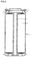
- FIG 2 illustrates a schematic cross-sectional view of the cylindrical battery.
- the electrode group 8 wound around the resin winding core 7 is fitted with the positive electrode current collecting plate 5 and the negative electrode current collecting plate 6 and is housed in the battery cell container 1.
- the negative-polarity electrodes are connected to the negative electrode current collecting plate 6 by means of welding or the like, and are electrically connected to the battery cell container 1 through negative leads 10.
- the positive electrode current collecting plate 5, and the negative electrode current collecting plate 6 are housed in the battery cell container 1, a welding jig is led through the central opening of the winding core 7 to weld the bottom of the battery cell container 1 and the negative leads 10 to each other. Thereafter, an electrolyte is injected into the battery cell container 1.
- the conductive top cover unit provided so as to seal the opening of the battery cell container 1 is located on the positive electrode current collecting plate 5.
- the top cover unit includes the top cover 3 and the top cover case 4. One end of the positive lead 9 is welded to the top cover case 4 and the other end thereof is welded to the positive electrode current collecting component 5, thereby electrically connecting the top cover unit and the positive electrode of the electrode group 8 to each other.
- the gasket 2 is provided between the battery cell container 1 and the top cover case 4. With this gasket 2, the opening of the battery cell container 1 is sealed and the battery cell container 1 and the top cover case 4 are electrically isolated from each other. Consequently, a secondary battery 11 is configured.
- the foreign matter may be contained in a raw material or may derive from dust generated from apparatus in a production phase or from machining swarf or the like generated by welding or cutting. If this foreign matter becomes caught between an electrode and a separator 18, the positive electrode 14 and the negative electrode 15 become micro-short-circuited through the foreign matter. Thus the voltage of the secondary battery 11 drops. Hence, aging is performed in order to detect whether or not a micro-short circuit is present in the secondary battery 11. When the secondary battery 11 is subjected to aging, the voltage thereof gently drops due to self-discharge if the battery is normal.
- the secondary battery 11 is measured before and after aging. If the voltage drop exceeds a predetermined value, the secondary battery 11 is detected as a micro-short-circuited secondary battery.
- FIG 3 illustrates a configuration of a battery module according to the present invention.
- An assembled battery 20 is configured in the manner that a plurality of secondary batteries 11 is connected in series, and both terminals of each secondary battery 11 are electrically connected to a cell controller IC 21.
- Each cell controller IC 21 includes an unillustrated cell voltage detecting circuit to detect the no-load voltage of each secondary battery 11.
- the cell controller IC 21 is also referred to as a voltage measuring unit.
- a group including a plurality of unit cells (battery cells) connected by way of one cell controller IC 21 is referred to as a battery group.
- a cell controller 30 is configured in the manner that a plurality of these assembled batteries 20 is arranged and electrically connected in series with a microcomputer 22.
- the term "no-load” refers to a state in which a load, such as a motor, is not connected, and does not include states in which any circuit loads, such as cell controller ICs 21, are connected.
- Each cell controller IC 21 is connected to the microcomputer 22 through a communication line.
- the microcomputer 22 controls various types of information, including charge/discharge information on the assembled batteries 20.
- a plurality of cell controllers 30 is electrically connected to a battery controller 40.
- the battery controller 40 manages the control of and information on each cell controller 30 through a communication line, and communicates with a host system, such as a vehicle. Note that in the present invention, the cell controller 30 and the battery controller 40 may also be referred to as battery controllers.
- the secondary batteries 11 are electrically connected to an inverter 41 for inverting DC power to three-phase AC power through positive terminals and negative terminals. Furthermore, this inverter 41 is electrically connected to a motor 42 for driving a vehicle.
- the microcomputer 22 includes a minimum value detecting unit, a reference value setting unit, a warning unit, a reference value changing unit, a typical value detecting unit, and a typical reference value calculating unit used to execute processes to be described later in FIGS. 4 to 8 .
- the minimum value detecting unit, the reference value setting unit, an abnormality determining unit (warning unit), the reference value changing unit, a temperature measuring unit, a stop time measuring unit, the typical value detecting unit, and the typical reference value calculating unit may be included in the battery controller 40, rather than in the microcomputer 22, to execute the processes therein.
- An abnormal voltage drop may occur also in the secondary batteries 11 mounted on the battery module.
- the cause for this is assumed to be that some sort of stress is applied to within the battery case by external impact, such as vibration, at the time of module manufacturing or after mounting on a vehicle or by the charge/discharge of a secondary battery and, consequently, foreign matter floating within a secondary battery 11 causes a micro-short circuit between the positive electrode 14 and the negative electrode 15.
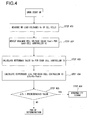
- FIG 4 illustrates a flow of determination used to detect an abnormal voltage drop in a secondary battery 11 within the battery module.
- a control unit of the microcomputer 22 plays a major role in carrying out the below-described steps of determination.
- the microcomputer 22 sends an instruction to measure a cell voltage to each cell controller IC 21.
- each cell controller IC 21 measures the no-load voltage (cell voltage) Vc of each secondary battery 11 which the cell controller IC controls (step 401), and transmits the measured no-load voltage Vc to the microcomputer 22.
- the cell controller IC 21 has begun to measure a cell voltage according to the cell voltage measurement instruction from the microcomputer 22.
- the battery module may be configured so that the cell controller IC 21 automatically measures a cell voltage even in the absence of the abovementioned instruction.
- each microcomputer 22 evaluates the minimum cell voltage value Vcmin of each cell controller IC 21 on the basis of the measured no-load voltage (cell voltage) Vc of each of the secondary batteries 11 (step 402, processing by the minimum value detecting unit). In addition, each microcomputer 22 sets a reference value Vs for each cell controller IC 21 on the basis of the detected no-load voltage (cell voltage) Vc of each of the secondary batteries 11 (step 403, processing by the reference value setting unit). A method for setting the reference value will be described later.
- each microcomputer 22 calculates a difference ⁇ Vc between the acquired reference value Vs and the minimum cell voltage value Vcmin (step 404).
- each microcomputer 22 determines whether or not the difference ⁇ Vc between the reference value Vs and the minimum cell voltage value Vcmin is larger than a previously specified value (predetermined value) (step 405, processing by the abnormality determining unit).
- the microcomputer 22 determines that an abnormal voltage drop has occurred in the secondary battery 11 in which the minimum cell voltage value Vcmin has been detected, and sends out an abnormality signal (alarm) to the battery controller 40 (step 406).
- the standard deviation ⁇ of each cell voltage detected for each cell controller IC 21 may be evaluated and a value n times the standard deviation ⁇ may be set as the predetermined value. At this time, the standard deviation ⁇ may be calculated with the minimum cell voltage value Vcmin excluded.
- the reference value is preferably a cell voltage when a secondary battery 11 undergoes a voltage drop due only to self-discharge.
- the amount of self-discharge varies according to the production tolerance of each secondary battery 11 or an aging period, and therefore, it is difficult to set the reference value to any fixed value.
- a method is available in which secondary batteries within the same cell controller IC are treated as comparative levels. For example, by defining the reference value with a maximum value among cell voltages within the same cell controller IC, it is possible to compare the amounts of voltage drop in respective secondary batteries on the basis of the cell voltage of a secondary battery whose amount of self-discharge is assumed to be minimum.
- FIG 5 illustrates another flow of determination used to detect an abnormal voltage drop in each secondary battery 11 within the battery module.
- the basics of the flow are the same as those of the flow in FIG 4 .
- the flow differs, however, in that a control unit of the battery controller 40 plays a major role in carrying out processing after voltage measurement.
- the battery controller 40 sends an instruction to measure a cell voltage to each cell controller IC 21 through the microcomputer 22.
- each cell controller IC 21 measures the no-load voltage (cell voltage) Vc of each of the secondary batteries 11 which the cell controller IC controls (step 501), and sends the measured no-load voltages Vc to the battery controller 40 through the microcomputer 22.
- the cell controller IC 21 has begun to measure a cell voltage according to the cell voltage measurement instruction from the battery controller 40.
- the battery module may be configured so that the cell controller IC 21 automatically measures a cell voltage even in the absence of the abovementioned instruction.
- the battery controller 40 evaluates a minimum value Vcmin of cell voltages for each cell controller IC 21 on the basis of the measured no-load voltage (cell voltage) Vc of each of the secondary batteries 11 (step 502, processing by a minimum value detecting unit). In addition, the battery controller 40 calculates a reference value Vs from respective cell voltages for each cell controller IC 21 on the basis of the detected no-load voltage (cell voltage) Vc of each of the secondary batteries 11 (step 503, processing by a reference value setting unit). A method for calculating the reference value will be described later.
- the battery controller 40 calculates a difference ⁇ Vc between the acquired reference value Vs for each cell controller IC 21 and the minimum cell voltage value Vcmin (step 504). In addition, the battery controller 40 determines whether or not the difference ⁇ Vc between the reference value Vs and the minimum cell voltage value Vcmin is larger than a previously specified value (predetermined value) (step 505, processing by an abnormality determining unit).
- the battery controller 40 determines that an abnormal voltage drop has occurred in the secondary battery 11 in which the minimum cell voltage value Vcmin has been detected, and sends out an abnormality signal (alarm) (step 506).
- FIG 6 illustrates a flow of determination used to detect an abnormal voltage drop in secondary batteries 11 within the battery module according to the temperature of each cell controller IC.
- the detected voltage of each cell controller IC varies widely, depending particularly on temperature. Accordingly, higher-accuracy abnormality determination is possible by changing the predetermined value according to temperature.
- steps 601 up to 604 the same processing as in steps 401 to 404 of FIG 4 is carried out.
- Each cell controller IC 21 includes therein a circuit for detecting the temperature thereof to detect cell controller IC temperature Tc when a flow of determination is put in operation (step 605, processing by a temperature measuring unit).
- the type of abnormality signal may be changed according to a temperature level.
- an abnormality signal A or an abnormality signal C is sent out in cases where Tc is lower than a or higher than b and determined to be abnormal
- the signal may be defined as a warning level (at which a vehicle is allowed to run for a certain length of time or over a certain distance, and then brought to an emergency stop).
- an abnormality signal B is sent out in cases where Tc is a or higher but not higher than b and determined to be abnormal, the vehicle may be brought to an emergency stop.
- an action to be taken can be selected optionally on the battery controller side according to the abnormality signal.
- step 606 if ⁇ Vc is larger than the predetermined value A, a determination is made that an abnormal voltage drop has occurred in the secondary battery 11 in which the minimum cell voltage value Vcmin has been detected. Thus, an abnormality signal A (alarm A) is sent out to the battery controller 40 (step 609). On the other hand, if ⁇ Vc is smaller than the predetermined value A, no problems are posed and processing is completed.
- step 607 if ⁇ Vc is larger than the predetermined value B, a determination is made that an abnormal voltage drop has occurred in the secondary battery 11 in which the minimum cell voltage value Vcmin has been detected. Thus, an abnormality signal B (alarm B) is sent out to the battery controller 40 (step 610). On the other hand, if ⁇ Vc is smaller than the predetermined value B, no problems are posed and processing is completed.
- step 608 if ⁇ Vc is larger than the predetermined value C, a determination is made that an abnormal voltage drop has occurred in the secondary battery 11 in which the minimum cell voltage value Vcmin has been detected. Thus, an abnormality signal C (alarm C) is sent out to the battery controller 40 (step 611). On the other hand, if ⁇ Vc is smaller than the predetermined value C, no problems are posed and processing is completed.
- FIG 7 illustrates a flow of determination used to detect an abnormal voltage drop in secondary batteries 11 within the battery module at the time of start-up according to a stop time until immediately before the start-up.
- steps 701 up to 704 the same processing as in steps 401 to 404 of FIG 4 is carried out.
- a timer capable of measuring a period of time during which a system (i.e. a vehicle on which secondary batteries 11 are mounted) is stop is provided within the battery controller 40 to detect, at the time of start-up, a stop time t until immediately before the start-up (step 705, processing by a stop time measuring unit). If the stop time t is shorter than a , a determination is made using a predetermined value A (step 706, processing by an abnormality determining unit). If t is a or larger but not larger than b, a determination is made using a predetermined value B (step 707, processing by the abnormality determining unit).
- a determination is made using a predetermined value C (step 708, processing by the abnormality determining unit).
- the cell voltage is kept almost constant by a capacity-adjusting function at the time of charge/discharge. If a micro-short circuit occurs, the cell voltage drops according to the scale of the short-circuit and the stop time. Accordingly, by changing a value for the determination according to the stop time, it is possible to precisely detect a secondary battery in which an abnormal voltage drop has occurred.
- a stop of a vehicle means that a power for driving is turned off at the vehicle and a system including charging and discharging at a secondary battery mounted in the vehicle is stopped and shut down.
- step 706 if ⁇ Vc is larger than the predetermined value A, a determination is made that an abnormal voltage drop has occurred in the secondary battery 11 in which the minimum cell voltage value Vcmin has been detected. Thus, an abnormality signal A (alarm A) is sent out to the battery controller 40 (step 709). On the other hand, if ⁇ Vc is smaller than the predetermined value A, no problems are posed and processing is completed.
- step 707 if ⁇ Vc is larger than the predetermined value B, a determination is made that an abnormal voltage drop has occurred in the secondary battery 11 in which the minimum cell voltage value Vcmin has been detected. Thus, an abnormality signal B (alarm B) is sent out to the battery controller 40 (step 710). On the other hand, if ⁇ Vc is smaller than the predetermined value B, no problems are posed and processing is completed.
- step 708 if ⁇ Vc is larger than the predetermined value C, a determination is made that an abnormal voltage drop has occurred in the secondary battery 11 in which the minimum cell voltage value Vcmin has been detected. Thus, an abnormality signal C (alarm C) is sent out to the battery controller 40 (step 711). On the other hand, if ⁇ Vc is smaller than the predetermined value C, no problems are posed and processing is completed.
- FIG 8 illustrates a flow of determination used to detect a voltage detection failure in a cell controller IC 21.
- a determination is made with regard to an abnormal voltage drop in secondary batteries 11, it is a prerequisite that the cell controller IC 21 correctly detects a cell voltage. For this reason, a flow of determination illustrated in FIG 8 is carried out either before or after the flow of determination on an abnormal voltage drop made in FIGS. 4 to 7 .
- the microcomputer 22 sends an instruction to measure a cell voltage to each cell controller IC 21.
- the cell controller IC 21 measures the no-load voltage (cell voltage) Vc of each secondary battery 11 which the cell controller IC controls (step 801), and transmits the measured no-load voltage Vc to the microcomputer 22.
- the cell controller IC 21 has begun to measure a cell voltage according to the cell voltage measurement instruction from the microcomputer 22.
- the battery module may be configured so that the cell controller IC 21 automatically measures a cell voltage even in the absence of the abovementioned instruction.
- the microcomputer 22 evaluates a typical value Vcc of cell voltages for each cell controller IC 21 on the basis of the measured no-load voltage (cell voltage) Vc of each of the secondary batteries 11 (step 802, processing by a typical value calculation unit).
- the typical value is calculated using an average value or a median value of detected respective cell voltages. At that time, the typical value may be calculated with the minimum value of the respective cell voltages excluded.
- the microcomputer 22 calculates a typical reference value Vms within the cell controller from the typical value of each of the cell controller ICs (step 803, processing by a typical reference value calculating unit).
- the typical reference value is calculated using an average value or a median value of typical values Vcc of respective cell controller ICs. At that time, the typical reference value may be calculated with the minimum value of the typical values Vcc of the respective cell controller ICs excluded.
- the microcomputer 22 calculates a difference ⁇ Vcc between the typical value Vcc of the cell controller IC and the typical reference value Vms within the cell controller (step 804).
- the microcomputer 22 determines whether or not the difference ⁇ Vcc between the typical value Vcc of the cell controller IC and the typical reference value Vms within the cell controller is larger than a previously specified value (predetermined value) (step 805).
- the microcomputer 22 determines that a voltage detection failure has occurred in the cell controller IC, and sends out an abnormality signal (alarm) (step 806).
- the battery module of the present embodiment it is possible to precisely detect an abnormal voltage drop in a secondary battery without being affected by a voltage variation due to a individual difference or a temperature change in a voltage measuring unit (for example, a cell controller IC).
- a voltage measuring unit for example, a cell controller IC
Landscapes
- Physics & Mathematics (AREA)
- General Physics & Mathematics (AREA)
- Engineering & Computer Science (AREA)
- Power Engineering (AREA)
- Chemical & Material Sciences (AREA)
- Manufacturing & Machinery (AREA)
- Mechanical Engineering (AREA)
- Chemical Kinetics & Catalysis (AREA)
- Electrochemistry (AREA)
- General Chemical & Material Sciences (AREA)
- Secondary Cells (AREA)
- Charge And Discharge Circuits For Batteries Or The Like (AREA)
- Tests Of Electric Status Of Batteries (AREA)
Abstract
Description
- The disclosure of the following priority application is herein incorporated by reference: Japanese Patent Application No.
2010-202628 filed September 10, 2010 - The present invention relates to a battery module configured by connecting a plurality of secondary batteries to be mounted on a vehicle or the like.
- For reasons of issues on global warming and exhaustible fuels, electric vehicles (EVs) and hybrid electric vehicles (HEVs) in which part of drive is assisted by an electric motor have been developed by respective automobile manufacturers. Thus, there has been an increasing demand for a high-capacity, high-output secondary battery as a power source of the vehicles. As a power source consistent with such a demand, a high-voltage secondary battery is now a focus of attention.
- Since a vehicular secondary battery carries a large amount of electric current, a micro-short circuit due to the mixing of foreign matter incurs reliability degradation or an increase in time degradation. The secondary battery has a structure in which a separator serving as an insulator is included between a positive electrode and a negative electrode. If any electrically-conductive foreign matter (for example, a metal piece) gets mixed between one of these electrodes and the separator, the positive and negative electrodes suffer a micro-short circuit, thus causing an abnormal voltage drop in the secondary battery.
- As one of techniques to detect an abnormal voltage drop in the secondary battery, there is mentioned the technique described in Japanese Laid-Open Patent Publication No.
2002-10511 - In Japanese Laid-Open Patent Publication No.
2002-10511 - That is, there has been the problem that if any abnormality is present in the cell controller itself due to effects of voltage variation caused by an individual difference or a temperature change, an erroneous determination is made that an abnormal voltage drop has occurred in a secondary battery which is not abnormal.
- According to the 1 st aspect of the present invention, a battery controller for controlling an assembled battery configured by connecting a plurality of battery groups each including a plurality of battery cells, comprises: a plurality of voltage measuring units that are provided respectively for the plurality of battery groups each to measure a voltage of each of the battery cells included in a corresponding battery group; a minimum value detecting unit that detects a minimum value of the battery cells for each of the plurality of battery groups based upon the voltage of each of the battery cells measured by a corresponding voltage measuring unit; a reference value setting unit that sets a reference value used to determine an abnormal voltage drop for each of the plurality of battery groups based upon the voltage of each of the battery cells measured by the corresponding voltage measuring unit; and/or an abnormality determining unit that makes a determination that an abnormal voltage drop is present, if a difference between the reference value and the minimum value exceeds a predetermined value, for each of the plurality of battery groups.
- According to the 2nd aspect of the present invention, in the battery controller according to the 1st aspect, it is preferred that the reference value setting unit sets a maximum voltage of the battery cells within a battery group as the reference value.
- According to the 3rd aspect of the present invention, in the battery controller according to the 1st aspect, it is preferred that the reference value setting unit sets an average voltage value of battery cells except a battery cell having a minimum voltage, within a battery group as the reference value.
- According to the 4th aspect of the present invention, in the battery controller according to the 1st aspect, it is preferred that the reference value setting unit sets a median voltage value of battery cells except a battery cell having a minimum voltage, within a battery group as the reference value.
- According to the 5th aspect of the present invention, in the battery controller according to the 1st aspect, it is preferred that the battery controller further comprises: a temperature measuring unit that measures a temperature of each of the plurality of voltage measuring units; and a reference value changing unit that changes the reference value based upon the temperature measured by the temperature measuring unit.
- According to the 6th aspect of the present invention, in the battery controller according to the 1st aspect, it is preferred that the battery controller further comprises: a stop time measuring unit that measures a time during which a vehicle mounted with the assembled battery is stopped; and a reference value changing unit that changes the reference value based upon the stop time measured by the stop time measuring unit.
- According to the 7th aspect of the present invention, in the battery controller according to the 1st aspect, it is preferred that the battery controller further comprises: a typical value calculating unit that calculates an average value or a median value of voltages of the battery cells as a typical value for each of the plurality of battery groups based upon the voltage of each of the battery cells measured by the corresponding voltage measuring unit; a typical reference value calculating unit that calculates an average value or a median value of typical values of the battery groups calculated by the typical value calculating unit as a typical reference value used to determine an abnormality in the voltage measuring units; and a second abnormality determining unit that makes a determination, for each of the plurality of battery groups, that an abnormality is present in a voltage measuring unit, if a difference between the typical value and the typical reference value exceeds a predetermined value.
- According to the 8th aspect of the present invention, in the battery controller according to the 1 st aspect, it is preferred that the battery controller further comprises: a first control unit; and a second control unit connected to the first control unit through a communication line, wherein: the first control unit includes the plurality of voltage measuring units; and the second control unit includes the minimum value detecting unit, the reference value setting unit and the abnormality determining unit and configured to receive voltages of the plurality of battery cells measured by the plurality of voltage measuring units of the first control unit.
- According to the 9th aspect of the present invention, in the battery controller according to the 8th aspect, it is preferred that the reference value setting unit sets a maximum voltage of the battery cells within a battery group as the reference value.
- According to the 10th aspect of the present invention, in the battery controller according to the 8th aspect, it is preferred that the reference value setting unit sets an average voltage of the battery cells except a battery cell having a minimum voltage, within a battery group as the reference value.
- According to the 11th aspect of the present invention, in the battery controller according to the 8th aspect, it is preferred that the reference value setting unit sets a median voltage value of the battery cells except a battery cell having a minimum voltage, within a battery group as the reference value.
- According to the 12th aspect of the present invention, in the battery controller according to the 8th aspect, it is preferred that the second control unit includes: a temperature measuring unit that measures a temperature of each of the plurality of voltage measuring units; and a reference value changing unit that changes the reference value based upon the temperature measured by the temperature measuring unit.
- According to the 13th aspect of the present invention, a method for detecting an abnormal voltage in an assembled battery configured by connecting a plurality of battery groups each including a plurality of battery cells, comprises: a voltage measuring step of measuring a voltage of each of the battery cells included in each of the plurality of battery groups; a minimum value detecting step of detecting a minimum value of the battery cells for each of the plurality of battery groups based upon the voltage of each of the battery cells measured in the voltage measuring step; a reference value setting step of setting a reference value used to determine an abnormal voltage drop for each of the plurality of battery groups based upon the voltage of each of the battery cells measured in the voltage measuring step; and an abnormality determining step of making a determination that an abnormal voltage drop is present, if a difference between the reference value and the minimum value exceeds a predetermined value, for each of the plurality of battery groups.
- According to the 14th aspect of the present invention, in the method for detecting an abnormal voltage in an assembled battery according to the 13th aspect, it is preferred that: a first control unit of the assembled battery executes the voltage measuring step; and a second control unit connected to the first control unit of the assembled battery through a communication line receives voltages of the plurality of battery cells measured by the voltage measuring step of the first control unit and executes the minimum value detecting step, the reference value setting step and the abnormality determining step.
-
-
FIG 1 is an exploded perspective view illustrating a structure of a cylindrical secondary battery; -
FIG 2 is a cross-sectional view illustrating the structure of the cylindrical secondary battery; -
FIG 3 is a conceptual view illustrating a battery module structure of the present invention; -
FIG 4 is a flowchart (1) used to make an abnormality determination on a secondary battery of the present invention; -
FIG 5 is a flowchart (2) used to make an abnormality determination on a secondary battery of the present invention; -
FIG 6 is a flowchart used to make an abnormality determination on a secondary battery of the present invention according to the temperature of a cell controller; -
FIG 7 is a flowchart used to make an abnormality determination on a secondary battery of the present invention according to a stop time; and -
FIG 8 is a flowchart used to make an abnormality determination on a cell controller IC of the present invention. - Hereinafter, embodiments for carrying out the present invention will be described according to
FIGS. 1 to 8 . -
FIG 1 is an exploded perspective view illustrating a structure of a cylindrical lithium-ion secondary battery which is one of vehicular secondary batteries. Apositive electrode 14 is a thin film of metal, such as aluminum, on both sides of which apositive electrode mixture 16 is coated. In the figure, a plurality ofpositive electrode tabs 12 is provided on an upper long side. Anegative electrode 15 is a thin film of metal, such as copper, on both sides of which anegative electrode mixture 17 is coated. In the figure, a plurality ofnegative electrode tabs 13 is provided on a lower long side. - These
positive electrode 14 andnegative electrode 15 are wound around aresin winding core 7 through a porous insulating separator 18. An outermost-circumferential separator is fastened with atape 19 to configure anelectrode group 8. Note that theelectrode group 8 can be configured no matter whether the direction of winding is clockwise or counterclockwise. - A positive electrode current collecting plate (positive electrode current collecting component) 5 and a negative electrode current collecting plate (negative electrode current collecting component) 6 are respectively fixed to the two ends of the tubular winding
core 7 by means of mutual fitting. Thepositive electrode tabs 12 are welded to the positive electrode current collectingcomponent 5 by, for example, an ultrasonic welding method. Likewise, thenegative electrode tabs 13 are welded to the negative electrode current collectingcomponent 6 by, for example, an ultrasonic welding method. Theelectrode group 8 wound around theresin winding core 7 is housed in a battery cell container (battery case) 1 also serving as a negative electrode terminal, with the positive electrodecurrent collecting plate 5 and the negative electrodecurrent collecting plate 6 attached to the electrode group. At this time, the negative electrodecurrent collecting plate 6 is electrically connected to thebattery cell container 1 through a negative lead (not illustrated). Thereafter, a non-aqueous electrolyte is injected into thebattery cell container 1. In addition, agasket 2 is provided between thebattery cell container 1 and atop cover case 4. With thisgasket 2, an opening of thebattery cell container 1 is sealed and the battery cell container is electrically isolated. A conductive top cover unit provided so as to seal an opening of thebattery cell container 1 is located on the positive electrodecurrent collecting plate 5. The top cover unit includes atop cover 3 and thetop cover case 4. One end of apositive lead 9 is welded to thetop cover case 4 and the other end thereof is welded to the positive electrodecurrent collecting component 5, thereby electrically connecting the top cover unit to a positive electrode of theelectrode group 8. - The
positive electrode mixture 16 includes an active positive electrode material, an electrically conductive positive electrode material, and a positive electrode binder. The active positive electrode material is preferably a lithium oxide. Examples of the lithium oxide include lithium cobaltate, lithium manganate, lithium nickelate, iron lithium phosphate, and lithium composite oxides (lithium oxides composed of two or more types of materials selected from the group consisting of cobalt, nickel and manganese). There is no limitation on the electrically conductive positive electrode material, as long as the material is a substance capable of facilitating the transfer of electrons produced by the occlusion/emission reaction of lithium ions in the positive electrode mixture to the positive electrode. Examples of the electrically conductive positive electrode material include graphite and acetylene black. The positive electrode binder is not limited in particular, as long as the binder can bind the active positive electrode material and the electrically conductive positive electrode material, and the positive electrode mixture and the positive electrode collector, and does not deteriorate significantly through contact with the non-aqueous electrolyte. Examples of the positive electrode binder include polyvinylidene fluoride (PVDF) and fluorine-containing rubber. A method for forming the positive electrode mixture is not limited, as long as the positive electrode mixture is formed on the positive electrode. As a method for forming the positive electrode mixture, there can be mentioned a method for coating a dispersion liquid composed of the constitutive substances of the positive electrode mixture onto the positive electrode. Examples of coating methods include a roll coating method and a slit die coating method. Examples of solvents to be used for the dispersion liquid include N-methylpyrrolidone (NMP) and water. One example of the coating thickness of thepositive electrode mixture 16 is approximately 40 µm on one side. - The
negative electrode mixture 17 includes an active negative electrode material, a negative electrode binder, and a thickener. Note that thenegative electrode mixture 17 may include an electrically conductive negative electrode material, such as acetylene black. In the present invention, graphite carbon is preferably used as the active negative electrode material. Use of graphite carbon enables the fabrication of a lithium-ion secondary battery cell for use in a plug-in hybrid vehicle and an electric vehicle requiring high capacity. A method for forming thenegative electrode mixture 17 is not limited, as long as thenegative electrode mixture 17 is formed on thenegative electrode 15. As a method for forming thenegative electrode mixture 17, there can be mentioned a method for coating a dispersion liquid composed of the constitutive substances of thenegative electrode mixture 17 onto thenegative electrode 15. Examples of coating methods include a roll coating method and a slit die coating method. One example of the coating thickness of thenegative electrode mixture 17 is approximately 40 µm on one side. - As the non-aqueous electrolyte, it is preferable to use a solution composed of a carbonate-based solvent in which lithium salt is dissolved. Examples of the lithium salt include lithium fluorophosphate (LiPF6) and lithium fluoborate (LiBF6). In addition, examples of the carbonate-based solvent include ethylene carbonate (EC), dimethyl carbonate (DMC), propylene carbonate (PC), methylethyl carbonate (MEC), and any one of the abovementioned solvents mixed with one or more than one type of solvent selected from the group consisting of the abovementioned solvents.
-
FIG 2 illustrates a schematic cross-sectional view of the cylindrical battery. Theelectrode group 8 wound around theresin winding core 7 is fitted with the positive electrodecurrent collecting plate 5 and the negative electrodecurrent collecting plate 6 and is housed in thebattery cell container 1. Of theelectrode group 8, the negative-polarity electrodes are connected to the negative electrodecurrent collecting plate 6 by means of welding or the like, and are electrically connected to thebattery cell container 1 through negative leads 10. - After the
electrode group 8, the positive electrodecurrent collecting plate 5, and the negative electrodecurrent collecting plate 6 are housed in thebattery cell container 1, a welding jig is led through the central opening of the windingcore 7 to weld the bottom of thebattery cell container 1 and the negative leads 10 to each other. Thereafter, an electrolyte is injected into thebattery cell container 1. The conductive top cover unit provided so as to seal the opening of thebattery cell container 1 is located on the positive electrodecurrent collecting plate 5. The top cover unit includes thetop cover 3 and thetop cover case 4. One end of thepositive lead 9 is welded to thetop cover case 4 and the other end thereof is welded to the positive electrodecurrent collecting component 5, thereby electrically connecting the top cover unit and the positive electrode of theelectrode group 8 to each other. Thegasket 2 is provided between thebattery cell container 1 and thetop cover case 4. With thisgasket 2, the opening of thebattery cell container 1 is sealed and thebattery cell container 1 and thetop cover case 4 are electrically isolated from each other. Consequently, asecondary battery 11 is configured. - There is the possibility of electrically conductive foreign matter getting mixed in the
secondary battery 11 thus fabricated. The foreign matter may be contained in a raw material or may derive from dust generated from apparatus in a production phase or from machining swarf or the like generated by welding or cutting. If this foreign matter becomes caught between an electrode and a separator 18, thepositive electrode 14 and thenegative electrode 15 become micro-short-circuited through the foreign matter. Thus the voltage of thesecondary battery 11 drops. Hence, aging is performed in order to detect whether or not a micro-short circuit is present in thesecondary battery 11. When thesecondary battery 11 is subjected to aging, the voltage thereof gently drops due to self-discharge if the battery is normal. In contrast, if the secondary battery is micro-short-circuited, a voltage drop due to the short circuit is superimposed on the voltage drop of the secondary battery. Consequently, the amount of voltage drop in the secondary battery becomes larger than that in a normal secondary battery. Accordingly, the amount of voltage drop in thesecondary battery 11 is measured before and after aging. If the voltage drop exceeds a predetermined value, thesecondary battery 11 is detected as a micro-short-circuited secondary battery. -
FIG 3 illustrates a configuration of a battery module according to the present invention. An assembledbattery 20 is configured in the manner that a plurality ofsecondary batteries 11 is connected in series, and both terminals of eachsecondary battery 11 are electrically connected to acell controller IC 21. Eachcell controller IC 21 includes an unillustrated cell voltage detecting circuit to detect the no-load voltage of eachsecondary battery 11. Thecell controller IC 21 is also referred to as a voltage measuring unit. In addition, a group including a plurality of unit cells (battery cells) connected by way of onecell controller IC 21 is referred to as a battery group. - A
cell controller 30 is configured in the manner that a plurality of these assembledbatteries 20 is arranged and electrically connected in series with amicrocomputer 22. Here, the term "no-load" refers to a state in which a load, such as a motor, is not connected, and does not include states in which any circuit loads, such ascell controller ICs 21, are connected. Eachcell controller IC 21 is connected to themicrocomputer 22 through a communication line. Themicrocomputer 22 controls various types of information, including charge/discharge information on the assembledbatteries 20. A plurality ofcell controllers 30 is electrically connected to abattery controller 40. Thebattery controller 40 manages the control of and information on eachcell controller 30 through a communication line, and communicates with a host system, such as a vehicle. Note that in the present invention, thecell controller 30 and thebattery controller 40 may also be referred to as battery controllers. - In addition, the
secondary batteries 11 are electrically connected to aninverter 41 for inverting DC power to three-phase AC power through positive terminals and negative terminals. Furthermore, thisinverter 41 is electrically connected to amotor 42 for driving a vehicle. - The
microcomputer 22 includes a minimum value detecting unit, a reference value setting unit, a warning unit, a reference value changing unit, a typical value detecting unit, and a typical reference value calculating unit used to execute processes to be described later inFIGS. 4 to 8 . Note that the minimum value detecting unit, the reference value setting unit, an abnormality determining unit (warning unit), the reference value changing unit, a temperature measuring unit, a stop time measuring unit, the typical value detecting unit, and the typical reference value calculating unit may be included in thebattery controller 40, rather than in themicrocomputer 22, to execute the processes therein. - An abnormal voltage drop may occur also in the
secondary batteries 11 mounted on the battery module. The cause for this is assumed to be that some sort of stress is applied to within the battery case by external impact, such as vibration, at the time of module manufacturing or after mounting on a vehicle or by the charge/discharge of a secondary battery and, consequently, foreign matter floating within asecondary battery 11 causes a micro-short circuit between thepositive electrode 14 and thenegative electrode 15. -
FIG 4 illustrates a flow of determination used to detect an abnormal voltage drop in asecondary battery 11 within the battery module. A control unit of themicrocomputer 22 plays a major role in carrying out the below-described steps of determination. - At the time of start-up, the
microcomputer 22 sends an instruction to measure a cell voltage to eachcell controller IC 21. Upon receipt of the instruction from themicrocomputer 22, eachcell controller IC 21 measures the no-load voltage (cell voltage) Vc of eachsecondary battery 11 which the cell controller IC controls (step 401), and transmits the measured no-load voltage Vc to themicrocomputer 22. Note that here, thecell controller IC 21 has begun to measure a cell voltage according to the cell voltage measurement instruction from themicrocomputer 22. However, without limitation to this configuration, the battery module may be configured so that thecell controller IC 21 automatically measures a cell voltage even in the absence of the abovementioned instruction. - Next, each
microcomputer 22 evaluates the minimum cell voltage value Vcmin of eachcell controller IC 21 on the basis of the measured no-load voltage (cell voltage) Vc of each of the secondary batteries 11 (step 402, processing by the minimum value detecting unit). In addition, eachmicrocomputer 22 sets a reference value Vs for eachcell controller IC 21 on the basis of the detected no-load voltage (cell voltage) Vc of each of the secondary batteries 11 (step 403, processing by the reference value setting unit). A method for setting the reference value will be described later. - Thereafter, each
microcomputer 22 calculates a difference ΔVc between the acquired reference value Vs and the minimum cell voltage value Vcmin (step 404). - In addition, each
microcomputer 22 determines whether or not the difference ΔVc between the reference value Vs and the minimum cell voltage value Vcmin is larger than a previously specified value (predetermined value) (step 405, processing by the abnormality determining unit). - If at this time, ΔVc is larger than the predetermined value, the
microcomputer 22 determines that an abnormal voltage drop has occurred in thesecondary battery 11 in which the minimum cell voltage value Vcmin has been detected, and sends out an abnormality signal (alarm) to the battery controller 40 (step 406). - On the other hand, if ΔVc is smaller than the predetermined value, no problems are posed and processing is completed.
- Here, it is assumed that a plurality of predetermined values can be set. Thus, an alarm level may be varied in such a manner as caution, and then warning, and then stop, each time the predetermined value is incremented. As an alternative method, the standard deviation σ of each cell voltage detected for each
cell controller IC 21 may be evaluated and a value n times the standard deviation σ may be set as the predetermined value. At this time, the standard deviation σ may be calculated with the minimum cell voltage value Vcmin excluded. - In addition, the reference value is preferably a cell voltage when a
secondary battery 11 undergoes a voltage drop due only to self-discharge. However, the amount of self-discharge varies according to the production tolerance of eachsecondary battery 11 or an aging period, and therefore, it is difficult to set the reference value to any fixed value. Hence, a method is available in which secondary batteries within the same cell controller IC are treated as comparative levels. For example, by defining the reference value with a maximum value among cell voltages within the same cell controller IC, it is possible to compare the amounts of voltage drop in respective secondary batteries on the basis of the cell voltage of a secondary battery whose amount of self-discharge is assumed to be minimum. In addition, by defining the reference value with an average value or a median value of respective cell voltages, except the minimum value thereof, within the same cell controller IC, it is possible to compare the amounts of voltage drop in respective secondary batteries on the basis of the cell voltage of a secondary battery whose amount of self-discharge is assumed to be typical. -
FIG 5 illustrates another flow of determination used to detect an abnormal voltage drop in eachsecondary battery 11 within the battery module. The basics of the flow are the same as those of the flow inFIG 4 . The flow differs, however, in that a control unit of thebattery controller 40 plays a major role in carrying out processing after voltage measurement. - At the time of start-up, the
battery controller 40 sends an instruction to measure a cell voltage to eachcell controller IC 21 through themicrocomputer 22. Upon receipt of the instruction from thebattery controller 40, eachcell controller IC 21 measures the no-load voltage (cell voltage) Vc of each of thesecondary batteries 11 which the cell controller IC controls (step 501), and sends the measured no-load voltages Vc to thebattery controller 40 through themicrocomputer 22. Note that here, thecell controller IC 21 has begun to measure a cell voltage according to the cell voltage measurement instruction from thebattery controller 40. However, without limitation to this configuration, the battery module may be configured so that thecell controller IC 21 automatically measures a cell voltage even in the absence of the abovementioned instruction. - Next, the
battery controller 40 evaluates a minimum value Vcmin of cell voltages for eachcell controller IC 21 on the basis of the measured no-load voltage (cell voltage) Vc of each of the secondary batteries 11 (step 502, processing by a minimum value detecting unit). In addition, thebattery controller 40 calculates a reference value Vs from respective cell voltages for eachcell controller IC 21 on the basis of the detected no-load voltage (cell voltage) Vc of each of the secondary batteries 11 (step 503, processing by a reference value setting unit). A method for calculating the reference value will be described later. - Thereafter, the
battery controller 40 calculates a difference ΔVc between the acquired reference value Vs for eachcell controller IC 21 and the minimum cell voltage value Vcmin (step 504). In addition, thebattery controller 40 determines whether or not the difference ΔVc between the reference value Vs and the minimum cell voltage value Vcmin is larger than a previously specified value (predetermined value) (step 505, processing by an abnormality determining unit). - If at this time, ΔVc is larger than the predetermined value, the
battery controller 40 determines that an abnormal voltage drop has occurred in thesecondary battery 11 in which the minimum cell voltage value Vcmin has been detected, and sends out an abnormality signal (alarm) (step 506). - On the other hand, if ΔVc is smaller than the predetermined value, no problems are posed and processing is completed.
- As an application example of the present invention,
FIG 6 illustrates a flow of determination used to detect an abnormal voltage drop insecondary batteries 11 within the battery module according to the temperature of each cell controller IC. The detected voltage of each cell controller IC varies widely, depending particularly on temperature. Accordingly, higher-accuracy abnormality determination is possible by changing the predetermined value according to temperature. Insteps 601 up to 604, the same processing as insteps 401 to 404 ofFIG 4 is carried out. - Each
cell controller IC 21 includes therein a circuit for detecting the temperature thereof to detect cell controller IC temperature Tc when a flow of determination is put in operation (step 605, processing by a temperature measuring unit). - If the cell controller IC temperature Tc is lower than a, a determination is made using a predetermined value A (
step 606, processing by an abnormality determining unit). If Tc is a or higher but not higher than b, a determination is made using a predetermined value B (step 607, processing by the abnormality determining unit). Likewise, if Tc is higher than b, a determination is made using a predetermined value C (step 608, processing by the abnormality determining unit). The type of abnormality signal may be changed according to a temperature level. - For example, if an abnormality signal A or an abnormality signal C is sent out in cases where Tc is lower than a or higher than b and determined to be abnormal, the signal may be defined as a warning level (at which a vehicle is allowed to run for a certain length of time or over a certain distance, and then brought to an emergency stop). Alternatively, if an abnormality signal B is sent out in cases where Tc is a or higher but not higher than b and determined to be abnormal, the vehicle may be brought to an emergency stop. Thus, an action to be taken can be selected optionally on the battery controller side according to the abnormality signal.
- In
step 606, if ΔVc is larger than the predetermined value A, a determination is made that an abnormal voltage drop has occurred in thesecondary battery 11 in which the minimum cell voltage value Vcmin has been detected. Thus, an abnormality signal A (alarm A) is sent out to the battery controller 40 (step 609). On the other hand, if ΔVc is smaller than the predetermined value A, no problems are posed and processing is completed. - In
step 607, if ΔVc is larger than the predetermined value B, a determination is made that an abnormal voltage drop has occurred in thesecondary battery 11 in which the minimum cell voltage value Vcmin has been detected. Thus, an abnormality signal B (alarm B) is sent out to the battery controller 40 (step 610). On the other hand, if ΔVc is smaller than the predetermined value B, no problems are posed and processing is completed. - In
step 608, if ΔVc is larger than the predetermined value C, a determination is made that an abnormal voltage drop has occurred in thesecondary battery 11 in which the minimum cell voltage value Vcmin has been detected. Thus, an abnormality signal C (alarm C) is sent out to the battery controller 40 (step 611). On the other hand, if ΔVc is smaller than the predetermined value C, no problems are posed and processing is completed. - As an application example of the present invention,
FIG 7 illustrates a flow of determination used to detect an abnormal voltage drop insecondary batteries 11 within the battery module at the time of start-up according to a stop time until immediately before the start-up. Insteps 701 up to 704, the same processing as insteps 401 to 404 ofFIG 4 is carried out. - A timer capable of measuring a period of time during which a system (i.e. a vehicle on which
secondary batteries 11 are mounted) is stop is provided within thebattery controller 40 to detect, at the time of start-up, a stop time t until immediately before the start-up (step 705, processing by a stop time measuring unit). If the stop time t is shorter than a, a determination is made using a predetermined value A (step 706, processing by an abnormality determining unit). If t is a or larger but not larger than b, a determination is made using a predetermined value B (step 707, processing by the abnormality determining unit). Likewise, if t is larger than b, a determination is made using a predetermined value C (step 708, processing by the abnormality determining unit). In the current battery module, the cell voltage is kept almost constant by a capacity-adjusting function at the time of charge/discharge. If a micro-short circuit occurs, the cell voltage drops according to the scale of the short-circuit and the stop time. Accordingly, by changing a value for the determination according to the stop time, it is possible to precisely detect a secondary battery in which an abnormal voltage drop has occurred. A stop of a vehicle means that a power for driving is turned off at the vehicle and a system including charging and discharging at a secondary battery mounted in the vehicle is stopped and shut down. - In
step 706, if ΔVc is larger than the predetermined value A, a determination is made that an abnormal voltage drop has occurred in thesecondary battery 11 in which the minimum cell voltage value Vcmin has been detected. Thus, an abnormality signal A (alarm A) is sent out to the battery controller 40 (step 709). On the other hand, if ΔVc is smaller than the predetermined value A, no problems are posed and processing is completed. - In
step 707, if ΔVc is larger than the predetermined value B, a determination is made that an abnormal voltage drop has occurred in thesecondary battery 11 in which the minimum cell voltage value Vcmin has been detected. Thus, an abnormality signal B (alarm B) is sent out to the battery controller 40 (step 710). On the other hand, if ΔVc is smaller than the predetermined value B, no problems are posed and processing is completed. - In
step 708, if ΔVc is larger than the predetermined value C, a determination is made that an abnormal voltage drop has occurred in thesecondary battery 11 in which the minimum cell voltage value Vcmin has been detected. Thus, an abnormality signal C (alarm C) is sent out to the battery controller 40 (step 711). On the other hand, if ΔVc is smaller than the predetermined value C, no problems are posed and processing is completed. -
FIG 8 illustrates a flow of determination used to detect a voltage detection failure in acell controller IC 21. When a determination is made with regard to an abnormal voltage drop insecondary batteries 11, it is a prerequisite that thecell controller IC 21 correctly detects a cell voltage. For this reason, a flow of determination illustrated inFIG 8 is carried out either before or after the flow of determination on an abnormal voltage drop made inFIGS. 4 to 7 . By making a determination on a voltage detection failure in eachcell controller IC 21 before the flow of determination on an abnormal voltage drop in eachsecondary battery 11, it is possible to previously assure that a determination on the abnormal voltage drop of thesecondary battery 11 can be made correctly. In addition, by carrying out a determination on a voltage detection failure in acell controller IC 21 after the flow of determination on an abnormal voltage drop in eachsecondary battery 11, it is possible to assure in an ex-post manner that a determination on an abnormal voltage drop in thesecondary battery 11 has been made correctly. - In cases where a
secondary battery 11 is used in, for example, a cold district, failures are liable to occur in acell controller IC 21. Accordingly, the flow of determination inFIG 8 is intended to periodically verify whether or not thiscell controller IC 21 operates normally. - At the time of start-up, the
microcomputer 22 sends an instruction to measure a cell voltage to eachcell controller IC 21. Upon receipt of the instruction from themicrocomputer 22, thecell controller IC 21 measures the no-load voltage (cell voltage) Vc of eachsecondary battery 11 which the cell controller IC controls (step 801), and transmits the measured no-load voltage Vc to themicrocomputer 22. Note that here, thecell controller IC 21 has begun to measure a cell voltage according to the cell voltage measurement instruction from themicrocomputer 22. However, without limitation to this configuration, the battery module may be configured so that thecell controller IC 21 automatically measures a cell voltage even in the absence of the abovementioned instruction. - Next, the
microcomputer 22 evaluates a typical value Vcc of cell voltages for eachcell controller IC 21 on the basis of the measured no-load voltage (cell voltage) Vc of each of the secondary batteries 11 (step 802, processing by a typical value calculation unit). The typical value is calculated using an average value or a median value of detected respective cell voltages. At that time, the typical value may be calculated with the minimum value of the respective cell voltages excluded. In addition, themicrocomputer 22 calculates a typical reference value Vms within the cell controller from the typical value of each of the cell controller ICs (step 803, processing by a typical reference value calculating unit). The typical reference value is calculated using an average value or a median value of typical values Vcc of respective cell controller ICs. At that time, the typical reference value may be calculated with the minimum value of the typical values Vcc of the respective cell controller ICs excluded. - Thereafter, the
microcomputer 22 calculates a difference ΔVcc between the typical value Vcc of the cell controller IC and the typical reference value Vms within the cell controller (step 804). - In addition, the
microcomputer 22 determines whether or not the difference ΔVcc between the typical value Vcc of the cell controller IC and the typical reference value Vms within the cell controller is larger than a previously specified value (predetermined value) (step 805). - If at this time, ΔVcc is larger than the predetermined value, the
microcomputer 22 determines that a voltage detection failure has occurred in the cell controller IC, and sends out an abnormality signal (alarm) (step 806). - On the other hand, if ΔVcc is smaller than the predetermined value, no problems are posed and processing is completed.
- As has been described heretofore, according to the battery module of the present embodiment, it is possible to precisely detect an abnormal voltage drop in a secondary battery without being affected by a voltage variation due to a individual difference or a temperature change in a voltage measuring unit (for example, a cell controller IC).
- The above described embodiments are examples, and various modifications can be made without departing from the scope of the invention.
Claims (14)
- A battery controller for controlling an assembled battery configured by connecting a plurality of battery groups each including a plurality of battery cells, comprising:a plurality of voltage measuring units that are provided respectively for the plurality of battery groups each to measure a voltage of each of the battery cells included in a corresponding battery group;a minimum value detecting unit that detects a minimum value of the battery cells for each of the plurality of battery groups based upon the voltage of each of the battery cells measured by a corresponding voltage measuring unit;a reference value setting unit that sets a reference value used to determine an abnormal voltage drop for each of the plurality of battery groups based upon the voltage of each of the battery cells measured by the corresponding voltage measuring unit; andan abnormality determining unit that makes a determination that an abnormal voltage drop is present, if a difference between the reference value and the minimum value exceeds a predetermined value, for each of the plurality of battery groups.
- The battery controller according to claim 1, wherein:the reference value setting unit sets a maximum voltage of the battery cells within a battery group as the reference value.
- The battery controller according to claim 1, wherein:the reference value setting unit sets an average voltage value of battery cells except a battery cell having a minimum voltage, within a battery group as the reference value.
- The battery controller according to claim 1, wherein:the reference value setting unit sets a median voltage value of battery cells except a battery cell having a minimum voltage, within a battery group as the reference value.
- The battery controller according to claim 1, further comprising:a temperature measuring unit that measures a temperature of each of the plurality of voltage measuring units; anda reference value changing unit that changes the reference value based upon the temperature measured by the temperature measuring unit.
- The battery controller according to claim 1, further comprising:a stop time measuring unit that measures a time during which a vehicle mounted with the assembled battery is stopped; anda reference value changing unit that changes the reference value based upon the stop time measured by the stop time measuring unit.
- The battery controller according to claim 1, further comprising:a typical value calculating unit that calculates an average value or a median value of voltages of the battery cells as a typical value for each of the plurality of battery groups based upon the voltage of each of the battery cells measured by the corresponding voltage measuring unit;a typical reference value calculating unit that calculates an average value or a median value of typical values of the battery groups calculated by the typical value calculating unit as a typical reference value used to determine an abnormality in the voltage measuring units; anda second abnormality determining unit that makes a determination, for each of the plurality of battery groups, that an abnormality is present in a voltage measuring unit, if a difference between the typical value and the typical reference value exceeds a predetermined value.
- The battery controller according to claim 1, further comprising:a first control unit; anda second control unit connected to the first control unit through a communication line, wherein:the first control unit includes the plurality of voltage measuring units; andthe second control unit includes the minimum value detecting unit, the reference value setting unit and the abnormality determining unit and configured to receive voltages of the plurality of battery cells measured by the plurality of voltage measuring units of the first control unit.
- The battery controller according to claim 8, wherein:the reference value setting unit sets a maximum voltage of the battery cells within a battery group as the reference value.
- The battery controller according to claim 8, wherein:the reference value setting unit sets an average voltage of the battery cells except a battery cell having a minimum voltage, within a battery group as the reference value.
- The battery controller according to claim 8, wherein:the reference value setting unit sets a median voltage value of the battery cells except a battery cell having a minimum voltage, within a battery group as the reference value.
- The battery controller according to claim 8, wherein
the second control unit includes:a temperature measuring unit that measures a temperature of each of the plurality of voltage measuring units; anda reference value changing unit that changes the reference value based upon the temperature measured by the temperature measuring unit. - A method for detecting an abnormal voltage in an assembled battery configured by connecting a plurality of battery groups each including a plurality of battery cells, comprising:a voltage measuring step of measuring a voltage of each of the battery cells included in each of the plurality of battery groups;a minimum value detecting step of detecting a minimum value of the battery cells for each of the plurality of battery groups based upon the voltage of each of the battery cells measured in the voltage measuring step;a reference value setting step of setting a reference value used to determine an abnormal voltage drop for each of the plurality of battery groups based upon the voltage of each of the battery cells measured in the voltage measuring step; andan abnormality determining step of making a determination that an abnormal voltage drop is present, if a difference between the reference value and the minimum value exceeds a predetermined value, for each of the plurality of battery groups.
- The method for detecting an abnormal voltage in an assembled battery according to claim 13, wherein:a first control unit of the assembled battery executes the voltage measuring step; anda second control unit connected to the first control unit of the assembled battery through a communication line receives voltages of the plurality of battery cells measured by the voltage measuring step of the first control unit and executes the minimum value detecting step, the reference value setting step and the abnormality determining step.
Applications Claiming Priority (1)
| Application Number | Priority Date | Filing Date | Title |
|---|---|---|---|
| JP2010202628A JP5235959B2 (en) | 2010-09-10 | 2010-09-10 | Battery controller and voltage abnormality detection method |
Publications (2)
| Publication Number | Publication Date |
|---|---|
| EP2428809A2 true EP2428809A2 (en) | 2012-03-14 |
| EP2428809A3 EP2428809A3 (en) | 2016-03-09 |
Family
ID=44644983
Family Applications (1)
| Application Number | Title | Priority Date | Filing Date |
|---|---|---|---|
| EP11177333.9A Withdrawn EP2428809A3 (en) | 2010-09-10 | 2011-08-11 | Battery controller and voltage abnormality detection method |
Country Status (5)
| Country | Link |
|---|---|
| US (1) | US20120062238A1 (en) |
| EP (1) | EP2428809A3 (en) |
| JP (1) | JP5235959B2 (en) |
| KR (1) | KR101273727B1 (en) |
| CN (1) | CN102403551B (en) |
Cited By (10)
| Publication number | Priority date | Publication date | Assignee | Title |
|---|---|---|---|---|
| WO2015086442A3 (en) * | 2013-12-09 | 2015-08-06 | Robert Bosch Gmbh | Method for transferring a minimum and/or a maximum value of a battery system parameter and battery system for carrying out such a method |
| EP3112157A1 (en) * | 2015-05-27 | 2017-01-04 | Canon Kabushiki Kaisha | Power supply apparatus, printer, and control method |
| EP3021450A4 (en) * | 2013-07-11 | 2017-03-01 | NGK Insulators, Ltd. | Device and method for specifying where abnormality has occurred in secondary battery system and program |
| EP3040732A4 (en) * | 2013-08-30 | 2017-06-21 | NGK Insulators, Ltd. | Device, method, and program for specifying abnormality-occurrence area of secondary battery system |
| EP3301465A1 (en) * | 2016-09-30 | 2018-04-04 | GS Yuasa International Ltd. | Energy storage apparatus, energy storage system, and method of determining state of energy storage apparatus |
| RU2663087C2 (en) * | 2014-03-10 | 2018-08-01 | Чанз Асендинг Энтерпрайз Ко., Лтд. | Determination of battery serviceability without turning it off without warning |
| EP3508867A4 (en) * | 2016-09-27 | 2019-09-04 | Huawei Technologies Co., Ltd. | Detection method and device for micro short circuit of battery |
| EP3557269A4 (en) * | 2016-12-16 | 2020-07-22 | Nio Nextev Limited | Online detection method for battery internal short-circuit |
| CN111480352A (en) * | 2017-09-12 | 2020-07-31 | 约翰·梅扎林瓜联合有限公司 | Edge-based location-specific alarm system for L TE networks |
| CN113358920A (en) * | 2021-05-17 | 2021-09-07 | 优利德科技(中国)股份有限公司 | Voltage drop measuring device and voltage drop measuring method |
Families Citing this family (22)
| Publication number | Priority date | Publication date | Assignee | Title |
|---|---|---|---|---|
| JP5263315B2 (en) * | 2011-02-14 | 2013-08-14 | 株式会社デンソー | Vehicle behavior data storage device |
| CN104272126B (en) * | 2012-04-27 | 2017-09-05 | 日立汽车系统株式会社 | Battery monitoring apparatus and battery system monitoring arrangement |
| JP2017500835A (en) * | 2013-10-18 | 2017-01-05 | マルー エムシーエス コー リミテッド | Electricity monitoring battery power system |
| US9906069B2 (en) * | 2014-07-28 | 2018-02-27 | Ford Global Technologies, Llc | Vehicle battery status detection by tracking a temperature gradient |
| CN104614675A (en) * | 2014-12-31 | 2015-05-13 | 普天新能源车辆技术有限公司 | Power battery group consistency detection method and device |
| CN104714187B (en) * | 2015-03-23 | 2018-10-23 | 重庆长安汽车股份有限公司 | Power battery abnormality determination method and system |
| CN105158715B (en) * | 2015-08-31 | 2018-08-03 | 惠州市蓝微电子有限公司 | A kind of high-accuracy voltage calibration method |
| CN105620304B (en) * | 2016-01-26 | 2018-01-02 | 华霆(合肥)动力技术有限公司 | Battery pack thermal run away monitoring device and electric automobile |
| CN106067572A (en) * | 2016-07-25 | 2016-11-02 | 江苏聚合新能源科技有限公司 | A kind of discharge control method of lithium ion battery bag |
| CN107472063B (en) * | 2017-08-10 | 2019-10-18 | 杭州衡源汽车科技有限公司 | A kind of battery failures check system and electric car |
| JP7043519B2 (en) | 2017-08-25 | 2022-03-29 | オッポ広東移動通信有限公司 | Terminal device and its battery safety monitoring method and monitoring system |
| CN109716579B (en) | 2017-08-25 | 2022-02-01 | Oppo广东移动通信有限公司 | Terminal equipment and battery safety monitoring method and monitoring system thereof |
| EP3907849A1 (en) | 2017-08-25 | 2021-11-10 | Guangdong Oppo Mobile Telecommunications Corp., Ltd. | Terminal device, battery system, and device for detecting battery abnormality |
| WO2019037109A1 (en) | 2017-08-25 | 2019-02-28 | 深圳市云中飞网络科技有限公司 | Terminal device, adapter, battery safety monitoring method and monitoring system |
| EP3557686B1 (en) | 2017-08-25 | 2021-02-17 | Guangdong Oppo Mobile Telecommunications Corp., Ltd. | Terminal device, battery component and battery protection board |
| FR3076908B1 (en) * | 2018-01-16 | 2021-01-01 | Renault Sas | METHOD OF DETECTION OF A FAILING CELL IN AN ELECTRIC BATTERY |
| JP2019158831A (en) * | 2018-03-16 | 2019-09-19 | 株式会社Gsユアサ | Method for inspection, inspection device, and learning model |
| DE102018215761A1 (en) * | 2018-09-17 | 2020-03-19 | Robert Bosch Gmbh | Method for monitoring an energy storage system |
| KR20210054331A (en) | 2019-11-05 | 2021-05-13 | 주식회사 엘지화학 | Apparatus for battery diagnosis, nergy storage system including same, and method thereof |
| CN110927589B (en) * | 2019-12-09 | 2023-03-21 | 天津市捷威动力工业有限公司 | Method for monitoring short circuit abnormality in battery on line |
| CN115220422B (en) * | 2022-06-02 | 2024-01-02 | 广州汽车集团股份有限公司 | Voltage detection method, device, vehicle and storage medium |
| KR20240069504A (en) * | 2022-11-11 | 2024-05-20 | 주식회사 엘지에너지솔루션 | Apparatus for managing battery pack and operating method of the same |
Citations (2)
| Publication number | Priority date | Publication date | Assignee | Title |
|---|---|---|---|---|
| JP2002010511A (en) | 2000-06-28 | 2002-01-11 | Nissan Motor Co Ltd | Capacity adjusting method for battery pack |
| JP2010202628A (en) | 2009-02-03 | 2010-09-16 | Japan Polypropylene Corp | Metallocene complex and olefin polymerization catalyst containing the same |
Family Cites Families (31)
| Publication number | Priority date | Publication date | Assignee | Title |
|---|---|---|---|---|
| JPH0926444A (en) * | 1995-07-13 | 1997-01-28 | Toshiba Syst Technol Kk | Dc current detection device |
| US5798702A (en) * | 1996-04-18 | 1998-08-25 | Suzuki Motor Corporation | Residual battery capacity display device for electric vehicle |
| JP3618472B2 (en) * | 1996-07-01 | 2005-02-09 | 富士通株式会社 | Battery unit and device using battery unit |
| US6332113B1 (en) * | 1996-10-07 | 2001-12-18 | Midtronics, Inc. | Electronic battery tester |
| US6104164A (en) * | 1998-10-20 | 2000-08-15 | Denso Corporation | Cell voltage detecting device for combination battery |
| JP3855497B2 (en) * | 1998-10-22 | 2006-12-13 | 株式会社デンソー | Charged / discharged state determination method and apparatus for assembled battery |
| US6255803B1 (en) * | 1999-08-10 | 2001-07-03 | Matsushita Electric Industrial Co., Ltd. | Method for detecting minor short in cells and method for detecting cell short in cells |
| JP3946391B2 (en) | 1999-09-29 | 2007-07-18 | 本田技研工業株式会社 | Power storage device remaining capacity detection device |
| JP2001174531A (en) * | 1999-12-15 | 2001-06-29 | Denso Corp | Abnormality detecting device of battery pack |
| US6140820A (en) * | 1999-12-27 | 2000-10-31 | Plug Power Inc. | Measuring cell voltages of a fuel cell stack |
| JP2001218376A (en) | 2000-02-03 | 2001-08-10 | Toyota Motor Corp | Device and method for controlling charring condition of single batteries constituting batter pack, and battery module using device, and electric-motor vehicle |
| US6417648B2 (en) * | 2000-06-28 | 2002-07-09 | Nissan Motor Co., Ltd. | Method of and apparatus for implementing capacity adjustment in battery pack |
| JP3849431B2 (en) * | 2001-01-30 | 2006-11-22 | 日産自動車株式会社 | Abnormality detection device for battery pack |
| JP3649135B2 (en) * | 2001-02-20 | 2005-05-18 | 日産自動車株式会社 | Abnormality detection device for battery pack |
| JP3772735B2 (en) * | 2001-11-29 | 2006-05-10 | 日産自動車株式会社 | Cell voltage detector |
| AU2003285252A1 (en) * | 2002-12-03 | 2004-06-23 | Hydrogenics Corporation | Method and apparatus for monitoring fuel cell voltages |
| KR100507469B1 (en) * | 2003-03-05 | 2005-08-09 | 현대자동차주식회사 | Method and apparatus for detecting voltage of a battery module of an electric vehicle |
| CA2467263A1 (en) * | 2003-05-14 | 2004-11-14 | Hydrogenics Corporation | Method, system and apparatus for testing electrochemical cells |
| JP2006333662A (en) * | 2005-05-27 | 2006-12-07 | Toyota Industries Corp | Device and method for judging deterioration degree of battery |
| JP2007311255A (en) * | 2006-05-19 | 2007-11-29 | Fuji Electric Systems Co Ltd | Battery pack status measuring device, battery pack deterioration determining method, and battery pack deterioration determining program |
| KR100839382B1 (en) * | 2006-10-16 | 2008-06-20 | 삼성에스디아이 주식회사 | Battery management system and driving method thereof |
| JP5248764B2 (en) * | 2006-11-02 | 2013-07-31 | パナソニック株式会社 | Storage element abnormality detection device, storage element abnormality detection method, and abnormality detection program thereof |
| JP5027005B2 (en) * | 2007-05-11 | 2012-09-19 | プライムアースEvエナジー株式会社 | Method for adjusting assembled battery and method for adjusting assembled battery with controller |
| KR100907375B1 (en) * | 2007-07-19 | 2009-07-10 | 현대자동차주식회사 | Method for detecting state of battery |
| JP5127383B2 (en) * | 2007-09-28 | 2013-01-23 | 株式会社日立製作所 | Battery integrated circuit and vehicle power supply system using the battery integrated circuit |
| JP5459946B2 (en) * | 2007-09-28 | 2014-04-02 | 株式会社日立製作所 | DC power supply for vehicle |
| JP5104416B2 (en) * | 2008-03-07 | 2012-12-19 | 日産自動車株式会社 | Abnormality detection device for battery pack |
| JP5386872B2 (en) | 2008-07-29 | 2014-01-15 | 株式会社デンソー | Battery monitoring and control device |
| JP2010104175A (en) * | 2008-10-24 | 2010-05-06 | Panasonic Corp | Fault diagnosis circuit, power supply device, and fault diagnosis method |
| JP5289083B2 (en) * | 2009-02-05 | 2013-09-11 | 三洋電機株式会社 | Secondary battery abnormality detection device and secondary battery device |
| US8183870B1 (en) * | 2009-02-12 | 2012-05-22 | The United States Of America As Represented By The Administrator Of The National Aeronautics And Space Administration | Battery system and method for sensing and balancing the charge state of battery cells |
-
2010
- 2010-09-10 JP JP2010202628A patent/JP5235959B2/en not_active Expired - Fee Related
-
2011
- 2011-08-11 EP EP11177333.9A patent/EP2428809A3/en not_active Withdrawn
- 2011-08-19 KR KR1020110082714A patent/KR101273727B1/en active IP Right Grant
- 2011-08-19 US US13/213,186 patent/US20120062238A1/en not_active Abandoned
- 2011-08-22 CN CN201110244090.5A patent/CN102403551B/en not_active Expired - Fee Related
Patent Citations (2)
| Publication number | Priority date | Publication date | Assignee | Title |
|---|---|---|---|---|
| JP2002010511A (en) | 2000-06-28 | 2002-01-11 | Nissan Motor Co Ltd | Capacity adjusting method for battery pack |
| JP2010202628A (en) | 2009-02-03 | 2010-09-16 | Japan Polypropylene Corp | Metallocene complex and olefin polymerization catalyst containing the same |
Cited By (20)
| Publication number | Priority date | Publication date | Assignee | Title |
|---|---|---|---|---|
| US10451685B2 (en) | 2013-07-11 | 2019-10-22 | Ngk Insulators, Ltd. | Secondary battery system and method for identifying abnormality of secondary battery system |
| EP3021450A4 (en) * | 2013-07-11 | 2017-03-01 | NGK Insulators, Ltd. | Device and method for specifying where abnormality has occurred in secondary battery system and program |
| EP3040732A4 (en) * | 2013-08-30 | 2017-06-21 | NGK Insulators, Ltd. | Device, method, and program for specifying abnormality-occurrence area of secondary battery system |
| US10203377B2 (en) | 2013-08-30 | 2019-02-12 | Ngk Insultors, Ltd. | Device, method, and non-transitory recording medium storing program for specifying abnormality-occurrence area of secondary battery system |
| WO2015086442A3 (en) * | 2013-12-09 | 2015-08-06 | Robert Bosch Gmbh | Method for transferring a minimum and/or a maximum value of a battery system parameter and battery system for carrying out such a method |
| US10490863B2 (en) | 2013-12-09 | 2019-11-26 | Robert Bosch Gmbh | Method for transferring a minimum and/or a maximum value of a battery system parameter and battery system for carrying out such a method |
| RU2663087C2 (en) * | 2014-03-10 | 2018-08-01 | Чанз Асендинг Энтерпрайз Ко., Лтд. | Determination of battery serviceability without turning it off without warning |
| EP3112157A1 (en) * | 2015-05-27 | 2017-01-04 | Canon Kabushiki Kaisha | Power supply apparatus, printer, and control method |
| US10245862B2 (en) | 2015-05-27 | 2019-04-02 | Canon Kabushiki Kaisha | Power supply apparatus, printer, and control method |
| EP3832328A1 (en) * | 2016-09-27 | 2021-06-09 | Huawei Technologies Co., Ltd. | Method and apparatus for detecting micro short circuit of battery |
| EP3508867A4 (en) * | 2016-09-27 | 2019-09-04 | Huawei Technologies Co., Ltd. | Detection method and device for micro short circuit of battery |
| US11215679B2 (en) | 2016-09-27 | 2022-01-04 | Huawei Technologies Co., Ltd. | Method and apparatus for detecting micro short circuit of battery |
| CN107887659A (en) * | 2016-09-30 | 2018-04-06 | 株式会社杰士汤浅国际 | Electrical storage device, accumulating system, the condition judgement method of electrical storage device |
| US10539626B2 (en) | 2016-09-30 | 2020-01-21 | Gs Yuasa International Ltd. | Energy storage apparatus, energy storage system, and method of determining state of energy storage apparatus |
| EP3301465A1 (en) * | 2016-09-30 | 2018-04-04 | GS Yuasa International Ltd. | Energy storage apparatus, energy storage system, and method of determining state of energy storage apparatus |
| CN107887659B (en) * | 2016-09-30 | 2022-03-01 | 株式会社杰士汤浅国际 | Power storage device, power storage system, and method for determining state of power storage device |
| EP3557269A4 (en) * | 2016-12-16 | 2020-07-22 | Nio Nextev Limited | Online detection method for battery internal short-circuit |
| CN111480352A (en) * | 2017-09-12 | 2020-07-31 | 约翰·梅扎林瓜联合有限公司 | Edge-based location-specific alarm system for L TE networks |
| CN111480352B (en) * | 2017-09-12 | 2021-10-08 | 约翰·梅扎林瓜联合有限公司 | Edge-based location-specific alarm system for LTE networks |
| CN113358920A (en) * | 2021-05-17 | 2021-09-07 | 优利德科技(中国)股份有限公司 | Voltage drop measuring device and voltage drop measuring method |
Also Published As
| Publication number | Publication date |
|---|---|
| KR101273727B1 (en) | 2013-06-12 |
| KR20120026966A (en) | 2012-03-20 |
| US20120062238A1 (en) | 2012-03-15 |
| JP5235959B2 (en) | 2013-07-10 |
| EP2428809A3 (en) | 2016-03-09 |
| CN102403551A (en) | 2012-04-04 |
| CN102403551B (en) | 2014-12-24 |
| JP2012060803A (en) | 2012-03-22 |
Similar Documents
| Publication | Publication Date | Title |
|---|---|---|
| EP2428809A2 (en) | Battery controller and voltage abnormality detection method | |
| TWI814765B (en) | Abnormality detection device, abnormality detection method, charge state estimation method, charge state estimation device and computer-readable medium for secondary battery | |
| US10454283B2 (en) | Battery system monitoring apparatus and electric storage device including the same | |
| JP4561859B2 (en) | Secondary battery system | |
| JP5287872B2 (en) | Secondary battery system | |
| JP5746856B2 (en) | Battery module manufacturing method | |
| WO2011007805A1 (en) | Monitoring system for lithium ion secondary cell and monitoring method for lithium ion secondary cell | |
| EP2175515A1 (en) | Battery internal short-circuit detecting device and method, battery pack, and electronic device system | |
| JP2016091613A (en) | Battery system and soc recovery method | |
| JP2013092398A (en) | Secondary battery deterioration determination system and deterioration determination method | |
| EP2291669B1 (en) | Method of diagnosing a malfunction in an abnormal voltage detecting apparatus, secondary battery system, and hybrid vehicle | |
| JP2013089311A (en) | Controller of laminated lithium ion battery | |
| US20230402666A1 (en) | Abnormality detection method, abnormality detection device, energy storage apparatus, and computer program | |
| US12061239B2 (en) | Battery system, vehicle including the same, and method for monitoring secondary battery | |
| US20230176134A1 (en) | Method for inspecting nonaqueous electrolyte rechargeable battery | |
| US20230335780A1 (en) | Secondary battery, electronic equipment, and electric tool | |
| US20230299436A1 (en) | Secondary battery, electronic equipment, and electric tool | |
| JP2023089452A (en) | Battery module inspection method | |
| CN116749828A (en) | Battery diagnosis system, vehicle provided with same, and battery diagnosis method | |
| JP2011190690A (en) | Battery control device and on-vehicle power source device |
Legal Events
| Date | Code | Title | Description |
|---|---|---|---|
| 17P | Request for examination filed |
Effective date: 20111209 |
|
| AK | Designated contracting states |
Kind code of ref document: A2 Designated state(s): AL AT BE BG CH CY CZ DE DK EE ES FI FR GB GR HR HU IE IS IT LI LT LU LV MC MK MT NL NO PL PT RO RS SE SI SK SM TR |
|
| AX | Request for extension of the european patent |
Extension state: BA ME |
|
| PUAI | Public reference made under article 153(3) epc to a published international application that has entered the european phase |
Free format text: ORIGINAL CODE: 0009012 |
|
| RAP1 | Party data changed (applicant data changed or rights of an application transferred) |
Owner name: HITACHI AUTOMOTIVE SYSTEMS, LTD. |
|
| PUAL | Search report despatched |
Free format text: ORIGINAL CODE: 0009013 |
|
| AK | Designated contracting states |
Kind code of ref document: A3 Designated state(s): AL AT BE BG CH CY CZ DE DK EE ES FI FR GB GR HR HU IE IS IT LI LT LU LV MC MK MT NL NO PL PT RO RS SE SI SK SM TR |
|
| AX | Request for extension of the european patent |
Extension state: BA ME |
|
| RIC1 | Information provided on ipc code assigned before grant |
Ipc: G01R 19/165 20060101ALI20160203BHEP Ipc: G01R 31/36 20060101AFI20160203BHEP Ipc: G01R 35/00 20060101ALI20160203BHEP |
|
| STAA | Information on the status of an ep patent application or granted ep patent |
Free format text: STATUS: THE APPLICATION HAS BEEN WITHDRAWN |
|
| 18W | Application withdrawn |
Effective date: 20160817 |