EP2428682A2 - Bidirektionales Radialgebläse mit selbsteinstellenden Schaufeln - Google Patents
Bidirektionales Radialgebläse mit selbsteinstellenden Schaufeln Download PDFInfo
- Publication number
- EP2428682A2 EP2428682A2 EP11181159A EP11181159A EP2428682A2 EP 2428682 A2 EP2428682 A2 EP 2428682A2 EP 11181159 A EP11181159 A EP 11181159A EP 11181159 A EP11181159 A EP 11181159A EP 2428682 A2 EP2428682 A2 EP 2428682A2
- Authority
- EP
- European Patent Office
- Prior art keywords
- vane
- stopper
- fan
- disc
- guide arm
- Prior art date
- Legal status (The legal status is an assumption and is not a legal conclusion. Google has not performed a legal analysis and makes no representation as to the accuracy of the status listed.)
- Withdrawn
Links
- 230000002457 bidirectional effect Effects 0.000 title abstract description 41
- 230000004044 response Effects 0.000 claims description 4
- 230000007935 neutral effect Effects 0.000 description 8
- 239000000463 material Substances 0.000 description 4
- 229910000831 Steel Inorganic materials 0.000 description 2
- 229910052782 aluminium Inorganic materials 0.000 description 2
- XAGFODPZIPBFFR-UHFFFAOYSA-N aluminium Chemical compound [Al] XAGFODPZIPBFFR-UHFFFAOYSA-N 0.000 description 2
- 239000002131 composite material Substances 0.000 description 2
- 239000012530 fluid Substances 0.000 description 2
- 229910052751 metal Inorganic materials 0.000 description 2
- 239000002184 metal Substances 0.000 description 2
- 238000000034 method Methods 0.000 description 2
- 239000010959 steel Substances 0.000 description 2
- 238000003466 welding Methods 0.000 description 2
- 238000005266 casting Methods 0.000 description 1
- 230000008859 change Effects 0.000 description 1
- 230000006870 function Effects 0.000 description 1
- 230000003993 interaction Effects 0.000 description 1
- 238000004519 manufacturing process Methods 0.000 description 1
- 230000007246 mechanism Effects 0.000 description 1
- 230000008569 process Effects 0.000 description 1
- XLYOFNOQVPJJNP-UHFFFAOYSA-N water Substances O XLYOFNOQVPJJNP-UHFFFAOYSA-N 0.000 description 1
Images




Classifications
-
- F—MECHANICAL ENGINEERING; LIGHTING; HEATING; WEAPONS; BLASTING
- F04—POSITIVE - DISPLACEMENT MACHINES FOR LIQUIDS; PUMPS FOR LIQUIDS OR ELASTIC FLUIDS
- F04D—NON-POSITIVE-DISPLACEMENT PUMPS
- F04D29/00—Details, component parts, or accessories
- F04D29/26—Rotors specially for elastic fluids
- F04D29/28—Rotors specially for elastic fluids for centrifugal or helico-centrifugal pumps for radial-flow or helico-centrifugal pumps
- F04D29/287—Rotors specially for elastic fluids for centrifugal or helico-centrifugal pumps for radial-flow or helico-centrifugal pumps with adjusting means
Definitions
- the subject matter disclosed herein relates to a bidirectional fan system. More specifically, the subject matter disclosed herein relates to a bidirectional centrifugal fan having at least one self-adjusting vane.
- a bidirectional centrifugal fan having a self-adjusting vane is disclosed.
- the fan includes a driving disc having a pivot pin extending therefrom; a vane pivotably attached to the pivot pin, the vane including an aperture extending at least partially therethrough; and a trailing disc including a guide arm for receiving the aperture of the vane.
- a first aspect of the disclosure provides a bi-directional centrifugal fan including: a driving disc having a pivot pin extending therefrom; a vane pivotably attached to the pivot pin, the vane including an aperture extending at least partially therethrough; and a trailing disc including a guide arm for receiving the aperture of the vane.
- a second aspect of the disclosure provides an apparatus comprising: a motor; and a bidirectional fan operably connected to the motor, the bidirectional fan including: a driving disc including a pivot pin extending therefrom; a vane pivotably attached to the pivot pin, the vane including an aperture extending at least partially therethrough; and a trailing disc including a guide arm for receiving the aperture of the vane, the guide arm configured to move along a length of the aperture.
- a third aspect of the disclosure provides a bi-directional centrifugal fan including: a driving disc having a plurality of pivot pins extending therefrom; a plurality of vanes each pivotably attached to one of the plurality of pivot pins, each of the plurality of vanes including a slot extending along a primary axis of the vane and at least partially therethrough along a secondary axis of the vane; and a trailing disc including: a guide arm for receiving the slot of the vane, the guide arm configured to move within the slot along the primary axis of the vane.
- a bidirectional centrifugal fan having a self-adjusting vane.
- the vane is configured to self-adjust when the direction of motion of the fan is changed from clockwise to anticlockwise, and vice versa. That is, intervention by an operator, e.g., a human operator and/or a mechanical or robotic tool, is unnecessary to adjust the position of the vane in response to a change in the direction of motion of the fan.
- the term "fan” includes devices used for accelerating a fluid.
- the device may include an impeller used to accelerate a fluid (e.g., water). While the example of a fan is predominately described herein, it is understood that the teachings of this disclosure may apply to impellers, pumps or other flow creating devices as well.
- bidirectional fan 10 includes a centrifugal fan.
- centrifugal fans may be used to accelerate a gas, and may be operably attached to a motor or other rotating device (e.g., motor 200 of FIG. 10 ).
- Centrifugal fans intake gas through a center region of the fan, and accelerate that gas before it exits at an angle normal to the intake angle (due to the centrifugal force caused by rotation of the fan vanes).
- bidirectional fans are fans capable of rotating in both clockwise and anticlockwise directions.
- bidirectional fan 10 is shown in a substantially neutral position (where vanes are neither forward leaning nor backward leaning).
- bidirectional fan 10 may include a driving disc 20 (shown as partially transparent for illustrative purposes), at least one vane 30, and a trailing disc 40. Interaction of these components will be further described herein.
- FIG. 2 a three-dimensional perspective view of driving disc 20 is shown according to an embodiment.
- driving disc 20 of FIG. 1 is shown (as partially transparent), the driving disc 20 having pivot pin(s) 50 extending therefrom.
- Pivot pins 50 may extend substantially perpendicularly from driving disc 20, and may be formed of any conventional material used in bidirectional fans, e.g., steel aluminum, composite(s), etc.
- Pivot pins 50 may allow for pivotable attachment of one or more vanes ( FIG. 1 , element number 30), and therefore may take any shape (e.g., rod-shaped, elongated spherical, etc.) capable of allowing vane 30 to pivot about pivot pin 50.
- An end of one or more pivot pins 50 may be configured to receive a stopper (e.g., a nut, pin, fastener, etc.), the stopper restricting movement of the vane 30 along an axis of rotation of the driving disc 20.
- a stopper e.g., a nut, pin, fastener, etc.
- an end portion of pivot pin 50 is machined in such a way that it may receive the stopper, for example, it may be threaded or otherwise truncated or pierced in order to receive a nut, pin, fastener, etc.
- Driving disc 20 is also shown including apertures 60, which may be used for connecting to a driving member (e.g., a shaft) of a motor (not shown), via, e.g., screws, nuts, bolts, fasteners, etc.
- trailing disc 40 may have a greater weight than driving disc 20, which may allow for a slight lag in rotation of trailing disc 40 with respect to driving disc 20 during operation of bidirectional fan 10.
- Trailing disc 40 is shown further including a plurality of guide arms 70, each for receiving an aperture (not shown) of a vane 30 ( FIG. 1 ).
- Guide arm 70 and trailing disc 40 may be formed of any conventional material used in bidirectional fans.
- guide arm 70 may be attached to trailing disc 40 in any conventional manner, and may be cast out of a continuous piece of material (e.g., a metal) or otherwise affixed (e.g., via welding or fastening) to trailing disc 40.
- Guide arm 70 may extend substantially perpendicularly from a surface of trailing disc 40.
- stoppers 80 cast with, affixed to, or otherwise attached to the surface of trailing disc 40, and located adjacent guide arm 70.
- a pair of stoppers 80 may be affixed to trailing disc 40, one on either side of each guide arm 70 along a circumference of trailing disc 40.
- stoppers 80 may be located radially inward of guide arm 70 with respect to a central (rotational) axis (A) of trailing disc 40. In one embodiment, stoppers 80 are equally spaced from guide arm 70 on opposing sides of the guide arm 70.
- support arms 90 which may be used to provide radial support between trailing disc 40 and driving disc 20 ( FIG. 1 ) during operation of bidirectional fan 10.
- Support arms 90 may be affixed or otherwise attached (e.g., via welding, casting, etc.) to trailing disc 40, and may be formed of any conventional material used in bidirectional fans (e.g., one or more composites, or a metal such as steel or aluminum).
- support arms 90 may be positioned on trailing disc 40 with clearance provided between outer surfaces of support arms 90 and an inner diameter of driving disc 20 ( FIG. 1 ).
- support arms 90 may be configured to provide radial clearance between an inner diameter (radially inner surface) of driving disc 20 an outer surface of all but one support arm 90. In this case, only one support arm 90 may contact the inner surface of driving disc 20 at any moment of operation of bidirectional fan 10. This may allow for sufficient radial support between driving disc 20 and trailing disc 40, while reducing frictional forces between driving disc 20 and trailing disc 40.
- anti-friction bearings or bushings may be used in place of or in conjunction with support arm 90 to provide radial support between driving disc 20 and trailing disc 40, while reducing frictional forces between driving disc 20 and trailing disc 40.
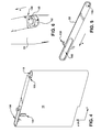
- FIGS. 4-6 a first three dimensional perspective view of a vane 30, a second three dimensional perspective view of a vane 30, and a top view of vane 30 are shown, respectively.
- Vane 30 is shown including an aperture 100 extending at least partially therethrough.
- aperture 100 may extend along an entire height (along y-axis) of vane 30, and may be configured to receive guide arm 70 ( FIGS. 1 , 3 ).
- Aperture 100 may further extend along at least a portion of the length (along x-axis) of vane 30, and may allow for movement of vane 30 with respect to guide arm 70 positioned therein ( FIG. 1 ).
- vane 30 is configured to move with respect to guide arm 70 ( FIGS.
- aperture 100 may be a substantially oblong circular slot, extending completely through vane 30 in only one direction (axial direction, A).
- Vane 30 may also include a second aperture 110, configured to pivotably attach vane 30 to pivot pin 50 ( FIGS. 1-2 , 6 ).
- second aperture 110 may extend substantially through vane 30 along one direction (A-axis).
- second aperture 110 and first aperture 100 may be configured to extend only partially through vane 30 (not shown).
- second aperture 110 may allow vane 30 to pivotably attach to pivot pin 50, such that vane 30 may rotate about the primary axis of pivot pin 50 (primary axis of pivot pin 50 being parallel with the A-axis in FIG. 4 ). This may allow for movement of vane 30 from a clockwise-leaning to an anti-clockwise-leaning position, and vice versa, within bidirectional fan 10.
- second aperture 110 may be positioned adjacent to a shoulder 120 (or, shelf, or other contour) that may allow for pivot pin 50 to be securely attached to vane 30, via, e.g., a nut, pin, or other fastener 52. Shelf 120 may allow for the secure attachment of vane to pivot pin 50 without disrupting the clearance between vane 30 and driving disc 20.
- Vane 30 may further include one or more protrusion(s) 130 extending therefrom, each protrusion 130 configured to engage one of the stoppers 80 ( FIG. 1 , 3 ) attached to trailing disc 40.
- protrusion 130 may include a guideway configured to engage a stopper 80 by at least partially surrounding the stopper 80.
- protrusion 130 may take the form of a hook or other multi-sided extension capable of contacting stopper 80 at more than one circumferential location.
- protrusion 130 may be configured as any shape that engages stopper 80 in response to a lag in rotation of trailing disc 40 with respect to driving disc 20.
- FIG. 7 a three-dimensional perspective view of bidirectional fan 10 in a neutral position (neither clockwise-leaning nor anti-clockwise-leaning vanes 30) is shown.
- vanes 30 are neither forward-leaning nor backward-leaning. That is, the radial ends of vanes 30 are at approximately their greatest radial distance from the central (rotational) axis (A) of bidirectional fan 10.
- a space exits between protrusions 130 (e.g., guideways) and stoppers 80, such that protrusions 130 do not engage stoppers 80.
- driving disc 20 has yet to initiate rotational motion about axis (A), and a portion of aperture 100 is radially outward (extending beyond) of an outer circumference of trailing disc 40.
- FIG. 8 a three-dimensional perspective view of bidirectional fan 10 is shown after rotation of driving disc 20 in a clockwise direction (indicated by arrow).
- driving disc 20 may be lighter (in weight) than trailing disc 40, such that when driving disc 20 is first rotated from a neutral position or any other inclined-vane position, by a drive shaft ( FIG. 10 , numeral 230, attached via apertures 60), trailing disc 40 does not immediately follow.
- vanes 30 are pivotably attached to the pivot pins 60 of driving disc 20, the radially inward portions of vanes 30 are rotated along with driving disc 20.
- vanes 30 rotate ahead of the radially outward portions of vanes 60 (e.g., near aperture 100), thereby producing a "leaning" vane 30.
- This leaning position of vane 30 may be secured by, e.g., the stopper 80 and protrusion 130. That is, during rotation of driving disc 20, but before substantial rotation of trailing disc 40, a protrusion 130 of vane 30 may engage (contact and/or rest upon) a stopper 80. In one embodiment, one protrusion 130 of each vane 30 may engage a stopper 80 located toward the direction of rotation of the driving disc 20.
- a protrusion 130 on the leading edge of vane 30 will engage with a stopper 80 located on the side of that leading edge.
- vane 30 may act as a connecting mechanism between driving disc 20 and trailing disc 40. More specifically, after engagement of protrusion 130 with stopper 80, trailing disc 40 may move in step with driving disc 20 in the clockwise rotation (such that trailing disc 40 is no longer trailing). This may allow bidirectional fan 10 to rotate about its central axis (A) in the clockwise direction, while keeping vanes 30 secure in an anti-clockwise-leaning direction.
- the angle of inclination of one or more vanes 30 by modifying: a position of protrusion 130 along the primary axis (x) of vane 30, a position of stopper 80 in the radial and/or circumferential directions, a size of aperture 100 (e.g., along primary axis (x) or along circumferential direction), or a position of guide arm 70 (either along axial direction or circumferential direction of trailing disc 40).
- the angle of inclination of one or more vanes 30 may be varied by dynamically modifying the position of stopper 80. That is, trailing disc 40 may be configured with a number of apertures for which to insert a stopper 80. Stopper 80 may be moved (e.g., by an operator during fan assembly / manufacture) from one aperture to another to vary the angle of inclination of a vane 30 during operation of the bidirectional fan 10.
- FIG. 9 the bidirectional fan 10 of FIGS. 7-8 is shown during rotation in the anti-clockwise direction.
- the driving disc 20 may begin its rotation from a neutral position ( FIG. 7 ) in the anti-clockwise direction.
- driving disc 20 may be lighter (in weight) than trailing disc 40, such that when driving disc 20 is first rotated from a neutral position or any inclined-vane position by a drive shaft ( FIG. 10 , numeral 230, attached via apertures 60), trailing disc 40 does not immediately follow. This applies to both clockwise and anti-clockwise rotation of driving disc 20 from the neutral position.
- FIG. 10 , numeral 230 attached via apertures 60
- trailing disc 40 may follow in step with driving disc 20.
- the lag in rotation between the driving disc 20 and trailing disc 40 allows for the vanes 30 to pivot about pivot pins 50 and alter their orientation (or lean).
- protrusion 130 on the leading edge of vane 30 may engage stopper 80 the stopper on that side of vane 30.
- protrusion 130 on the leading edge of vane 30 is shown as engaging stopper 80, it is also possible that protrusion 130 on the trailing edge of vane 30 could be configured to engage a stopper 80 on that side of vane 30.
- stopper 80 may be located radially closer to axis A than shown herein. In this case, a protrusion 130 on the trailing edge of vane 30 may engage a stopper on that side of vane 30.
- stopper 80 and protrusion 130 are not required to engage vanes 30 in a particular orientation (clockwise leaning or anti-clockwise leaning).
- the length of aperture 100 ( FIGS. 4-5 ) along the primary axis (x) of vane 30 may be modified to control how far vanes 30 may lean when leading disc 20 rotates with respect to trailing disc 40 (producing the lag described herein).
- the length of aperture 100 along the primary axis (x) may be such that an inner surface of the radially outward portion of aperture 100 engages guide arm 70 after rotation of leading disc 20 with respect to trailing disc 40. This allows the inner surface of aperture 100 to pull trailing disc 40, via contact with guide arm 70.
- use of protrusions 130 and/or stoppers 80 may be unnecessary in order to self-adjust vanes 30 in bidirectional fan 10.
- bidirectional fan 10 may be rotated from an engaged clockwise rotation position, to a neutral position, to an engaged anti-clockwise rotation position, without the need to manually adjust vanes 30. That is, vanes 30 may be adjusted from clock-wise leaning, to neutral, to anti-clockwise leaning simply by rotating a drive shaft (not shown) connected to apertures 60.
- FIG. 10 a cut-away view of a motor assembly 200 including bidirectional fan 10 is shown according to an embodiment.
- bidirectional fan 10 may be coupled to a motor body 220 via a shaft 230. Operation of motor assembly 200 is omitted for brevity, but motor assembly 200 (including motor body 220) may function as any conventional motor assembly configured to drive a flow creating device (e.g., a fan or impeller or pump).
- a flow creating device e.g., a fan or impeller or pump.
Landscapes
- Engineering & Computer Science (AREA)
- Mechanical Engineering (AREA)
- General Engineering & Computer Science (AREA)
- Structures Of Non-Positive Displacement Pumps (AREA)
Applications Claiming Priority (1)
| Application Number | Priority Date | Filing Date | Title |
|---|---|---|---|
| US12/881,308 US8662846B2 (en) | 2010-09-14 | 2010-09-14 | Bidirectional fan having self-adjusting vane |
Publications (2)
| Publication Number | Publication Date |
|---|---|
| EP2428682A2 true EP2428682A2 (de) | 2012-03-14 |
| EP2428682A3 EP2428682A3 (de) | 2017-06-07 |
Family
ID=44582708
Family Applications (1)
| Application Number | Title | Priority Date | Filing Date |
|---|---|---|---|
| EP11181159.2A Withdrawn EP2428682A3 (de) | 2010-09-14 | 2011-09-13 | Bidirektionales Radialgebläse mit selbsteinstellenden Schaufeln |
Country Status (3)
| Country | Link |
|---|---|
| US (1) | US8662846B2 (de) |
| EP (1) | EP2428682A3 (de) |
| JP (1) | JP5798418B2 (de) |
Cited By (6)
| Publication number | Priority date | Publication date | Assignee | Title |
|---|---|---|---|---|
| CN104595233A (zh) * | 2014-11-21 | 2015-05-06 | 江苏国泉泵业制造有限公司 | 一种直线型骨线双向轴流泵水力设计方法 |
| CN105216997A (zh) * | 2015-11-04 | 2016-01-06 | 倪忠 | 船用桨式推进器装置 |
| CN107264757A (zh) * | 2017-06-26 | 2017-10-20 | 吴其兵 | 一种船舶推进装置 |
| CN110901316A (zh) * | 2019-11-29 | 2020-03-24 | 哈尔滨工程大学 | 一种拍动推进式推进器和推进系统及水陆两栖车 |
| WO2022089262A1 (zh) * | 2020-10-28 | 2022-05-05 | 青岛海尔空调器有限总公司 | 贯流风扇及空调器 |
| EP4435170A1 (de) | 2023-03-20 | 2024-09-25 | Arçelik Anonim Sirketi | Haushaltsgerät |
Families Citing this family (12)
| Publication number | Priority date | Publication date | Assignee | Title |
|---|---|---|---|---|
| CN104533828B (zh) * | 2014-11-21 | 2017-08-08 | 江苏国泉泵业制造有限公司 | 一种双向轴流泵水力设计方法 |
| CN106949090B (zh) * | 2017-04-24 | 2023-03-31 | 浙江理工大学 | 一种可调节叶片的离心通风机装置 |
| CN106870449B (zh) * | 2017-04-24 | 2023-03-28 | 浙江理工大学 | 可调节叶片的离心通风机装置 |
| CN108105125A (zh) * | 2017-12-18 | 2018-06-01 | 卧龙电气集团股份有限公司 | 一种集成多旋向风扇 |
| KR102119006B1 (ko) * | 2018-08-03 | 2020-06-04 | 한국수자원공사 | 펌프의 가변형 임펠러 |
| CN108953230A (zh) * | 2018-08-06 | 2018-12-07 | 南京磁谷科技有限公司 | 一种离心风机扩压器结构 |
| CN113261693B (zh) * | 2021-04-27 | 2025-05-06 | 河南农业大学 | 一种循环风机扇叶可调的烟叶密集烤房 |
| CN113202819B (zh) * | 2021-05-31 | 2024-05-28 | 河海大学 | 基于可调节叶片数量的轴伸贯流泵用导流装置及控制方法 |
| CN113264379B (zh) * | 2021-07-19 | 2021-09-10 | 南通九港通机械科技有限公司 | 一种粉末输送装置的动力元件及其加工方法 |
| JP7294710B1 (ja) | 2022-02-09 | 2023-06-20 | Necプラットフォームズ株式会社 | シロッコファン、シロッコファンユニット及び送風方法 |
| CN114458618B (zh) * | 2022-03-22 | 2022-12-09 | 西安交通大学 | 一种正反调节可逆多翼离心风机叶轮装置及风机 |
| JP7408049B1 (ja) | 2022-11-11 | 2024-01-05 | 昇 望月 | 撹拌翼、撹拌方法、撹拌翼の組立方法 |
Family Cites Families (15)
| Publication number | Priority date | Publication date | Assignee | Title |
|---|---|---|---|---|
| GB1430596A (en) | 1972-07-06 | 1976-03-31 | Rolls Royce | Multi-bladed fans |
| US3932054A (en) | 1974-07-17 | 1976-01-13 | Western Engineering & Mfg. Co. | Variable pitch axial fan |
| JPS5742200U (de) * | 1980-08-15 | 1982-03-08 | ||
| US4412783A (en) | 1981-10-08 | 1983-11-01 | Thermo King Corporation | Centrifugal fan wheel with changeable pitch blades |
| DE3248760C2 (de) * | 1982-12-31 | 1984-10-31 | Siemens AG, 1000 Berlin und 8000 München | Axiallüfter mit sich selbst entsprechend der Drehrichtung einstellenden Lüfterflügeln |
| JPS61151100U (de) * | 1985-03-11 | 1986-09-18 | ||
| FR2595417A1 (fr) * | 1986-03-04 | 1987-09-11 | Curtila Serge | Dispositif a pales du type turbine, ventilateur, pompe ou autres |
| US4662819A (en) | 1986-04-10 | 1987-05-05 | American Standard Inc. | Centrifugal fan with variable blade pitch |
| US5800058A (en) * | 1995-11-06 | 1998-09-01 | The Research Foundation Of State University Of New York | Vortex elimination device |
| JP4191863B2 (ja) * | 1999-11-05 | 2008-12-03 | 独立行政法人 日本原子力研究開発機構 | 可変ノズル機構付きタービン膨張機 |
| US6547520B2 (en) * | 2001-05-24 | 2003-04-15 | Carrier Corporation | Rotating vane diffuser for a centrifugal compressor |
| US6699013B2 (en) | 2002-05-31 | 2004-03-02 | Quantum Corporation | Forced air cooling fan having pivotal fan blades for unidirectional air flow |
| US20060078423A1 (en) | 2004-10-08 | 2006-04-13 | Nonlinear Tech, Inc. | Bi-directional Blowers for Cooling Laptop Computers |
| US7270512B2 (en) * | 2005-08-24 | 2007-09-18 | General Electric Company | Stacked steampath and grooved bucket wheels for steam turbines |
| ATE509204T1 (de) * | 2008-07-28 | 2011-05-15 | Bombardier Transp Gmbh | Bidirektionales radialgebläse |
-
2010
- 2010-09-14 US US12/881,308 patent/US8662846B2/en not_active Expired - Fee Related
-
2011
- 2011-09-08 JP JP2011195531A patent/JP5798418B2/ja not_active Expired - Fee Related
- 2011-09-13 EP EP11181159.2A patent/EP2428682A3/de not_active Withdrawn
Non-Patent Citations (1)
| Title |
|---|
| None |
Cited By (8)
| Publication number | Priority date | Publication date | Assignee | Title |
|---|---|---|---|---|
| CN104595233A (zh) * | 2014-11-21 | 2015-05-06 | 江苏国泉泵业制造有限公司 | 一种直线型骨线双向轴流泵水力设计方法 |
| CN105216997A (zh) * | 2015-11-04 | 2016-01-06 | 倪忠 | 船用桨式推进器装置 |
| CN105216997B (zh) * | 2015-11-04 | 2017-05-10 | 倪忠 | 船用桨式推进器装置 |
| CN107264757A (zh) * | 2017-06-26 | 2017-10-20 | 吴其兵 | 一种船舶推进装置 |
| CN107264757B (zh) * | 2017-06-26 | 2019-01-04 | 吴其兵 | 一种船舶推进装置 |
| CN110901316A (zh) * | 2019-11-29 | 2020-03-24 | 哈尔滨工程大学 | 一种拍动推进式推进器和推进系统及水陆两栖车 |
| WO2022089262A1 (zh) * | 2020-10-28 | 2022-05-05 | 青岛海尔空调器有限总公司 | 贯流风扇及空调器 |
| EP4435170A1 (de) | 2023-03-20 | 2024-09-25 | Arçelik Anonim Sirketi | Haushaltsgerät |
Also Published As
| Publication number | Publication date |
|---|---|
| JP2012062886A (ja) | 2012-03-29 |
| US20120063892A1 (en) | 2012-03-15 |
| EP2428682A3 (de) | 2017-06-07 |
| JP5798418B2 (ja) | 2015-10-21 |
| US8662846B2 (en) | 2014-03-04 |
Similar Documents
| Publication | Publication Date | Title |
|---|---|---|
| US8662846B2 (en) | Bidirectional fan having self-adjusting vane | |
| EP3296572B1 (de) | Lüfterkopfteil, vertikale und wandmontierte lüfter, haushaltsgerät und luftblasverfahren | |
| CA2862280C (fr) | Aube pour soufflante de turboreacteur | |
| US1445402A (en) | Disappearing electric fan | |
| US4662823A (en) | Air turbulence blades for ceiling fans | |
| US20200224671A1 (en) | Ceiling fan blade | |
| US20080253896A1 (en) | High efficiency fan blades with airflow-directing baffle elements | |
| US20090155076A1 (en) | Shrouded Dual-Swept Fan Impeller | |
| BRPI0908752B1 (pt) | Sistema de hélices contra-rotativas para turbomáquina de aeronave, turbomáquina para aeronave e processo de pilotagem de um sistema de hélices contra-rotativas para turbomáquina de aeronave | |
| US10082147B2 (en) | Regulator assembly and centrifugal compressor | |
| US20110058932A1 (en) | Variable stator vane assemblies | |
| CA2662744A1 (en) | Centrifugal force bearing with steady pitching moment | |
| CN110435877A (zh) | 一种自适应气动变距螺旋桨 | |
| EP3932799B1 (de) | Rotorrückhaltevorrichtung mit integriertem lager und blattwinkelverstellung | |
| US7484934B2 (en) | Method and apparatus for propelling an intercepted fluid | |
| GB2412947A (en) | Variable stator vane connection | |
| CN212074399U (zh) | 螺旋桨变距装置以及设有该装置的飞行器 | |
| CN103210183B (zh) | 改变螺旋桨螺距用的液压装置 | |
| WO2015090318A1 (en) | Axial flow fan with blades twisted according to a blade pitch ratio that decreases (quasi) linearly with the radial position | |
| KR101119204B1 (ko) | 가변적인 설정 각도를 가진 블레이드를 위한 유동 보상이있는 제어 레버의 부착 | |
| CN111852941B (zh) | 用于吊扇的叶片 | |
| JP2000009097A (ja) | 送風機用羽根車 | |
| US12098729B2 (en) | Ceiling fan blade | |
| CN220505393U (zh) | 轴流风轮、空调外机及空调器 | |
| CN216887217U (zh) | 一种飞行器 |
Legal Events
| Date | Code | Title | Description |
|---|---|---|---|
| AK | Designated contracting states |
Kind code of ref document: A2 Designated state(s): AL AT BE BG CH CY CZ DE DK EE ES FI FR GB GR HR HU IE IS IT LI LT LU LV MC MK MT NL NO PL PT RO RS SE SI SK SM TR |
|
| AX | Request for extension of the european patent |
Extension state: BA ME |
|
| PUAI | Public reference made under article 153(3) epc to a published international application that has entered the european phase |
Free format text: ORIGINAL CODE: 0009012 |
|
| PUAL | Search report despatched |
Free format text: ORIGINAL CODE: 0009013 |
|
| AK | Designated contracting states |
Kind code of ref document: A3 Designated state(s): AL AT BE BG CH CY CZ DE DK EE ES FI FR GB GR HR HU IE IS IT LI LT LU LV MC MK MT NL NO PL PT RO RS SE SI SK SM TR |
|
| AX | Request for extension of the european patent |
Extension state: BA ME |
|
| RIC1 | Information provided on ipc code assigned before grant |
Ipc: F04D 29/28 20060101AFI20170503BHEP |
|
| PUAL | Search report despatched |
Free format text: ORIGINAL CODE: 0009013 |
|
| STAA | Information on the status of an ep patent application or granted ep patent |
Free format text: STATUS: REQUEST FOR EXAMINATION WAS MADE |
|
| 17P | Request for examination filed |
Effective date: 20171207 |
|
| RBV | Designated contracting states (corrected) |
Designated state(s): AL AT BE BG CH CY CZ DE DK EE ES FI FR GB GR HR HU IE IS IT LI LT LU LV MC MK MT NL NO PL PT RO RS SE SI SK SM TR |
|
| STAA | Information on the status of an ep patent application or granted ep patent |
Free format text: STATUS: THE APPLICATION IS DEEMED TO BE WITHDRAWN |
|
| 18D | Application deemed to be withdrawn |
Effective date: 20190402 |