EP2428670A1 - Treiberschaltung für eine Einspritzventilanordnung und Diagnosemethode - Google Patents
Treiberschaltung für eine Einspritzventilanordnung und Diagnosemethode Download PDFInfo
- Publication number
- EP2428670A1 EP2428670A1 EP11191576A EP11191576A EP2428670A1 EP 2428670 A1 EP2428670 A1 EP 2428670A1 EP 11191576 A EP11191576 A EP 11191576A EP 11191576 A EP11191576 A EP 11191576A EP 2428670 A1 EP2428670 A1 EP 2428670A1
- Authority
- EP
- European Patent Office
- Prior art keywords
- drive circuit
- fault
- voltage
- switch
- fuel injector
- Prior art date
- Legal status (The legal status is an assumption and is not a legal conclusion. Google has not performed a legal analysis and makes no representation as to the accuracy of the status listed.)
- Granted
Links
- 238000002405 diagnostic procedure Methods 0.000 title description 27
- 239000000446 fuel Substances 0.000 claims abstract description 198
- 238000000034 method Methods 0.000 claims abstract description 56
- 238000001514 detection method Methods 0.000 claims abstract description 30
- 230000008929 regeneration Effects 0.000 claims description 67
- 238000011069 regeneration method Methods 0.000 claims description 67
- 238000007599 discharging Methods 0.000 claims description 10
- 238000004590 computer program Methods 0.000 claims description 8
- 238000012546 transfer Methods 0.000 claims description 8
- 239000003990 capacitor Substances 0.000 description 38
- 238000002347 injection Methods 0.000 description 32
- 239000007924 injection Substances 0.000 description 32
- 238000012360 testing method Methods 0.000 description 16
- 238000010586 diagram Methods 0.000 description 14
- 230000004044 response Effects 0.000 description 12
- 230000000694 effects Effects 0.000 description 5
- 230000003213 activating effect Effects 0.000 description 4
- 230000008901 benefit Effects 0.000 description 3
- 230000007423 decrease Effects 0.000 description 3
- 238000006073 displacement reaction Methods 0.000 description 3
- 238000002485 combustion reaction Methods 0.000 description 2
- 230000008602 contraction Effects 0.000 description 2
- 238000013500 data storage Methods 0.000 description 2
- 239000002283 diesel fuel Substances 0.000 description 2
- 238000004146 energy storage Methods 0.000 description 2
- 230000006870 function Effects 0.000 description 2
- 238000005259 measurement Methods 0.000 description 2
- 238000012986 modification Methods 0.000 description 2
- 230000004048 modification Effects 0.000 description 2
- 230000009286 beneficial effect Effects 0.000 description 1
- 230000000295 complement effect Effects 0.000 description 1
- 230000003247 decreasing effect Effects 0.000 description 1
- 239000012530 fluid Substances 0.000 description 1
- 230000000977 initiatory effect Effects 0.000 description 1
- 238000012545 processing Methods 0.000 description 1
- 230000036962 time dependent Effects 0.000 description 1
Images


Classifications
-
- F—MECHANICAL ENGINEERING; LIGHTING; HEATING; WEAPONS; BLASTING
- F02—COMBUSTION ENGINES; HOT-GAS OR COMBUSTION-PRODUCT ENGINE PLANTS
- F02D—CONTROLLING COMBUSTION ENGINES
- F02D41/00—Electrical control of supply of combustible mixture or its constituents
- F02D41/20—Output circuits, e.g. for controlling currents in command coils
- F02D41/2096—Output circuits, e.g. for controlling currents in command coils for controlling piezoelectric injectors
-
- F—MECHANICAL ENGINEERING; LIGHTING; HEATING; WEAPONS; BLASTING
- F02—COMBUSTION ENGINES; HOT-GAS OR COMBUSTION-PRODUCT ENGINE PLANTS
- F02D—CONTROLLING COMBUSTION ENGINES
- F02D41/00—Electrical control of supply of combustible mixture or its constituents
- F02D41/22—Safety or indicating devices for abnormal conditions
- F02D41/221—Safety or indicating devices for abnormal conditions relating to the failure of actuators or electrically driven elements
-
- F—MECHANICAL ENGINEERING; LIGHTING; HEATING; WEAPONS; BLASTING
- F02—COMBUSTION ENGINES; HOT-GAS OR COMBUSTION-PRODUCT ENGINE PLANTS
- F02D—CONTROLLING COMBUSTION ENGINES
- F02D41/00—Electrical control of supply of combustible mixture or its constituents
- F02D41/20—Output circuits, e.g. for controlling currents in command coils
- F02D2041/2003—Output circuits, e.g. for controlling currents in command coils using means for creating a boost voltage, i.e. generation or use of a voltage higher than the battery voltage, e.g. to speed up injector opening
- F02D2041/2006—Output circuits, e.g. for controlling currents in command coils using means for creating a boost voltage, i.e. generation or use of a voltage higher than the battery voltage, e.g. to speed up injector opening by using a boost capacitor
-
- F—MECHANICAL ENGINEERING; LIGHTING; HEATING; WEAPONS; BLASTING
- F02—COMBUSTION ENGINES; HOT-GAS OR COMBUSTION-PRODUCT ENGINE PLANTS
- F02D—CONTROLLING COMBUSTION ENGINES
- F02D41/00—Electrical control of supply of combustible mixture or its constituents
- F02D41/20—Output circuits, e.g. for controlling currents in command coils
- F02D2041/202—Output circuits, e.g. for controlling currents in command coils characterised by the control of the circuit
- F02D2041/2051—Output circuits, e.g. for controlling currents in command coils characterised by the control of the circuit using voltage control
-
- F—MECHANICAL ENGINEERING; LIGHTING; HEATING; WEAPONS; BLASTING
- F02—COMBUSTION ENGINES; HOT-GAS OR COMBUSTION-PRODUCT ENGINE PLANTS
- F02D—CONTROLLING COMBUSTION ENGINES
- F02D41/00—Electrical control of supply of combustible mixture or its constituents
- F02D41/20—Output circuits, e.g. for controlling currents in command coils
- F02D2041/202—Output circuits, e.g. for controlling currents in command coils characterised by the control of the circuit
- F02D2041/2058—Output circuits, e.g. for controlling currents in command coils characterised by the control of the circuit using information of the actual current value
-
- F—MECHANICAL ENGINEERING; LIGHTING; HEATING; WEAPONS; BLASTING
- F02—COMBUSTION ENGINES; HOT-GAS OR COMBUSTION-PRODUCT ENGINE PLANTS
- F02D—CONTROLLING COMBUSTION ENGINES
- F02D41/00—Electrical control of supply of combustible mixture or its constituents
- F02D41/20—Output circuits, e.g. for controlling currents in command coils
- F02D2041/2068—Output circuits, e.g. for controlling currents in command coils characterised by the circuit design or special circuit elements
- F02D2041/2072—Bridge circuits, i.e. the load being placed in the diagonal of a bridge to be controlled in both directions
-
- F—MECHANICAL ENGINEERING; LIGHTING; HEATING; WEAPONS; BLASTING
- F02—COMBUSTION ENGINES; HOT-GAS OR COMBUSTION-PRODUCT ENGINE PLANTS
- F02D—CONTROLLING COMBUSTION ENGINES
- F02D41/00—Electrical control of supply of combustible mixture or its constituents
- F02D41/20—Output circuits, e.g. for controlling currents in command coils
- F02D2041/2086—Output circuits, e.g. for controlling currents in command coils with means for detecting circuit failures
- F02D2041/2089—Output circuits, e.g. for controlling currents in command coils with means for detecting circuit failures detecting open circuits
-
- F—MECHANICAL ENGINEERING; LIGHTING; HEATING; WEAPONS; BLASTING
- F02—COMBUSTION ENGINES; HOT-GAS OR COMBUSTION-PRODUCT ENGINE PLANTS
- F02D—CONTROLLING COMBUSTION ENGINES
- F02D41/00—Electrical control of supply of combustible mixture or its constituents
- F02D41/20—Output circuits, e.g. for controlling currents in command coils
- F02D2041/2086—Output circuits, e.g. for controlling currents in command coils with means for detecting circuit failures
- F02D2041/2093—Output circuits, e.g. for controlling currents in command coils with means for detecting circuit failures detecting short circuits
-
- F—MECHANICAL ENGINEERING; LIGHTING; HEATING; WEAPONS; BLASTING
- F02—COMBUSTION ENGINES; HOT-GAS OR COMBUSTION-PRODUCT ENGINE PLANTS
- F02D—CONTROLLING COMBUSTION ENGINES
- F02D41/00—Electrical control of supply of combustible mixture or its constituents
- F02D41/02—Circuit arrangements for generating control signals
- F02D41/04—Introducing corrections for particular operating conditions
- F02D41/06—Introducing corrections for particular operating conditions for engine starting or warming up
- F02D41/062—Introducing corrections for particular operating conditions for engine starting or warming up for starting
Definitions
- the present invention relates to a drive circuit for an injector arrangement having a diagnostic means for detecting a fault, and a diagnostic method for the drive circuit of an injector arrangement.
- the drive circuit is especially, although not exclusively, for an injector arrangement in an internal combustion engine, the injector arrangement including an injector of the type having a piezoelectric actuator for controlling injector valve needle movement.
- Automotive vehicle engines are generally equipped with fuel injectors for injecting fuel (e.g., gasoline or diesel fuel) into the individual cylinders or intake manifold of the engine.
- fuel e.g., gasoline or diesel fuel
- the engine fuel injectors are coupled to a fuel rail which contains high pressure fuel that is delivered by way of a fuel delivery system.
- conventional fuel injectors typically employ a valve that is actuated to open and to close in order to control the amount of fluid fuel metered from the fuel rail and injected into the corresponding engine cylinder or intake manifold.
- Piezoelectric fuel injectors employ piezoelectric actuators made of a stack of piezoelectric elements arranged mechanically in series for opening and for closing an injection valve to meter fuel injected into the engine. Piezoelectric fuel injectors are well known for use in automotive engines.
- the metering of fuel with a piezoelectric fuel injector is generally achieved by controlling the electrical voltage potential applied to the piezoelectric elements to vary the amount of expansion and contraction of the piezoelectric elements.
- the amount of expansion and contraction of the piezoelectric elements varies the travel distance of a valve piston and, thus, the amount of fuel that is passed through the fuel injector.
- Piezoelectric fuel injectors offer the ability to meter precisely a small amount of fuel.
- each bank of injectors has its own drive circuit for controlling operation of the injectors.
- the circuitry includes a power supply, such as a transformer, which steps-up the voltage V S generated by the power supply, i.e. from 12 Volts to a higher voltage, and storage capacitors for storing charge and, thus, energy. The higher voltage is applied across the storage capacitors which are used to power the charging and discharging of the piezoelectric fuel injectors for each injection event.
- Drive circuits have also been developed, as described in WO 2005/028836A1 , which do not require a dedicated power supply, such as a transformer.
- These drive circuits enables the voltage applied across the storage capacitors, and thus the piezoelectric fuel injectors, to be controlled dynamically. This is achieved by using two storage capacitors which are alternately connected to an injector arrangement. One of the storage capacitors is connected to the injector arrangement during a discharge phase when a discharge current flows through the injector arrangement, initiating an injection event. The other storage capacitor is connected to the injector arrangement during a charging phase, terminating the injection event. A regeneration switch is used at the end of the charging phase, before a later discharge phase, to replenish the storage capacitors.
- faults may occur in a drive circuit.
- safety critical systems such as diesel engine fuel injection systems
- a fault in the drive circuit may lead to a failure of the injection system, which could consequentially result in a catastrophic failure of the engine.
- a robust diagnostic system is therefore required to detect critical failure modes of piezoelectric actuators, and of the associated drive circuits, particularly whilst the drive circuit is in use.
- An aim of the invention is therefore to provide a diagnostic tool that is capable of detecting critical failure modes, or fault response characteristics, of an injector arrangement, and the associated drive circuits, and a method of operating the diagnostic tool.
- a drive circuit for an injector arrangement comprising a fuel injector, the drive circuit comprising diagnostic means operable: a) to sense a measured voltage between the injector and a known voltage level, the measured voltage being biased with respect to the known voltage to a predicted voltage unless the drive circuit has a fault; and b) to provide a fault signal on sensing of a measured voltage that differs from the predicted voltage.
- the drive circuit comprises a robust diagnostic system that is capable of detecting critical failure modes of the drive circuit, preventing failure of the drive circuit and the injector arrangement to which the drive circuit is connected.
- the diagnostic means uses a voltage associated with the fuel injector in order to detect the fault and to identify the type of fault.
- the drive circuit may further comprise selector switch means operable to select the fuel injector into the drive circuit and to deselect the fuel injector from the drive circuit.
- selector switch means operable to select the fuel injector into the drive circuit and to deselect the fuel injector from the drive circuit.
- the fuel injector may also be connected to and removed from the drive circuit by operation of the selector switch means.
- the predicted voltage may be the voltage between the fuel injector and the known voltage level when the injector is deselected from the drive circuit.
- the diagnostic means is capable of detecting a short circuit fault associated with the fuel injector. Thus, it is possible to detect the short circuit without having to select the injector (and hence connect it to the drive circuit), restricting the damage caused to it and the rest of the drive circuit by a short circuit fault.
- the diagnostic means is, preferably, capable of detecting an open circuit fault associated with the fuel injector.
- the predicted voltage may be substantially the sum of the known voltage and a voltage across the fuel injector when the fuel injector is selected in the drive circuit.
- the selector switch means may be operable to enable detection of a fault.
- the selector switch means is operable prior to detection of the fault.
- open circuit faults associated with the fuel injector can be detected when voltage is being sensed.
- the signal may be provided if the measured voltage is outside a tolerance voltage of the predicted voltage. This provides the benefit that the diagnostic means only provides a signal where the fuel injector is unable to function satisfactorily.
- the measured voltage may be sensed across part of a potential divider connected to the injector and the known voltage.
- the potential divider may be connected to a high voltage rail.
- the injector may have a high side and the diagnostic means may be operable to sense a measured voltage between the high side of the fuel injector and the known voltage.
- the low side of the injector may be connected a low voltage rail.
- the low voltage rail may, in use, be at a lower voltage than the high voltage rail.
- the divider may comprise at least two resistive elements. The resistive elements may each have a high resistance.
- the diagnostic means may be in a connection of the drive circuit to a ground potential.
- the diagnostic means may be operable to sense a detected current.
- the diagnostic means may also be operable by sensing a current to provide a signal on detection of a fault.
- the signal is provided when the detected current is at variance from a threshold current.
- the diagnostic means uses a current associated with the fuel injector, in order to detect a fault.
- the type of short circuit fault can be determined by the sensing current that is used to determine the presence of a fault.
- the signal may be provided when the detected current is greater than the threshold current.
- the diagnostic means may comprise a resistive element through which the detected current is sensed.
- the connection of the drive circuit to the ground potential may be connected to charge storage means.
- the connection of the drive circuit to the ground potential may be connected to a discharge switch.
- the drive circuit may comprise first charge storage means (e.g. comprising a capacitor) for operative connection with the fuel injector during a charging phase so as to cause a charge current to flow therethrough.
- the drive circuit may comprise second charge storage means (e.g. comprising a capacitor) for operative connection with the fuel injector during a discharge phase so as to permit a discharge current to flow therethrough.
- the drive circuit may comprise switch means for operably controlling the connection of the fuel injector to the first charge storage means or the second charge storage means.
- the discharging phase may initiate an injection event, and the charging phase may terminate the injection event, or vice versa. In another embodiment there may be only one charge storage means.
- the switch means may comprise a charge switch operable to close so as to activate the charging phase.
- a charge switch operable to close so as to activate the charging phase.
- the switch means may comprise a discharge switch operable to close so as to activate the discharge phase.
- a discharge switch operable to close so as to activate the discharge phase.
- a low side to ground potential short circuit fault can be detected at start up if there is residual charge on the fuel injector.
- the drive circuit may comprise a power supply means.
- the drive circuit may comprise regeneration switch means. Operating the regeneration switch provides an advantage of enabling detection of a fault. Preferably, the regeneration switch is operated prior to the detection of the fault.
- the regeneration switch means may be operable at the end of the charging phase to transfer charge. The operation of the regeneration switch means may transfer charge from the power supply means to the first charge storage means, before a subsequent discharging phase.
- the drive circuit may be deliberately tripped at start-up when sensing current to detect a fault in order to rule out high side and low side to ground short circuit faults. Note that in this mode of operation, low side to ground short circuit faults may only be detected by using the regeneration switch means if there is no charge, if any, on the fuel injector.
- the regeneration switch is operated during normal running conditions to detect a fault.
- Charge may be transferred from the first to the second charge storage means via an energy storage device.
- the drive circuit is particularly suitable for use with fuel injectors comprising a piezoelectric actuator, but other fuel injector types are also envisaged (e.g. solenoid actuated).
- a drive circuit for an injector arrangement comprising a fuel injector, the drive circuit comprising diagnostic means in a connection of the drive circuit to a ground potential, the diagnostic means being operable: a) to sense a detected current; and b) to provide a signal on detection of a fault, wherein the signal is provided when the detected current is at variance from a threshold current.
- This aspect of the invention provides a robust diagnostic system to detect critical failure modes of the drive circuit, preventing failure of the drive circuit and the injector arrangement to which it is connected.
- the diagnostic means uses a current associated with the fuel injector, in order to detect a fault. The type of short circuit fault can be determined from the sensed current.
- the signal may be provided when the detected current is greater than the threshold current.
- the connection of the drive circuit to the ground potential may be connected to charge storage means.
- the charge storage means may comprise first charge storage means for operative connection with the fuel injector during a charging phase so as to cause a charge current to flow therethrough. Additionally, the charge storage means may comprise second charge storage means for operative connection with the fuel injection during a discharge phase so as to permit a discharge current to flow therethrough.
- connection of the drive circuit to the ground potential may be connected to switch means for operably controlling the connection of the fuel injector to the first charge storage means or the second charge storage means.
- the switch means typically includes one or more of a charge switch operable to close so as to activate the charging phase and a discharge switch operable to close so as to activate the discharging phase.
- the connection of the drive circuit to the ground potential may be connected to the discharge switch.
- the drive circuit may comprise a power supply means.
- the drive circuit may comprise regeneration switch means.
- the regeneration switch means may be operable at the end of the charging phase to transfer charge from the power supply means to the first charge storage means, before a subsequent discharging phase.
- the drive circuit may comprise selector switch means. It may be beneficial to have the selector switch means operable to select the fuel injector into the drive circuit so as to enable a high side to ground potential short circuit fault to be detected.
- the second aspect of the invention may take any of the optional features of the first aspect of the invention.
- a drive circuit for an injector arrangement comprising a fuel injector, the drive circuit comprising: i) first charge storage means for operative connection with the fuel injector during a charging phase so as to cause a charge current to flow therethrough; ii) second charge storage means for operative connection with the fuel injector during a discharge phase so as to permit a discharge current to flow therethrough; iii) switch means for operably controlling the connection of the fuel injector to the first charge storage means or the second charge storage means; and diagnostic means operable to provide a signal on detection of a fault.
- the switch means is operable prior to detection of the fault.
- the third aspect of the invention may take any of the optional features of the first or second aspects of the invention.
- an injector bank for an automotive engine, the bank comprising a fuel injector and a drive circuit according to any of the first, second or third aspects of the invention, wherein the fuel injector is operable by the drive circuit.
- an engine control module for controlling the operation of an engine, the engine comprising a microprocessor for controlling the operation of the engine, a memory for recording data, and a drive circuit according to any of the first, second or third aspects of the invention, wherein the drive circuit is controllable by the microprocessor.
- a method of detecting faults in a drive circuit for an injector arrangement comprising a fuel injector, the method comprising: a) sensing a measured voltage between the injector and a known voltage level, the measured voltage being biased with respect to the known voltage to a predicted voltage unless the drive circuit has a fault; and b) providing a fault signal on sensing of a measured voltage that differs from the predicted voltage.
- the method may comprise operating selector switch means to select the fuel injector into the drive circuit.
- Selector switch means may be operated to deselect the fuel injector from the drive circuit.
- the selector switch means is operated to enable detection of a fault.
- the selector switch means may be operated prior to detection of the fault.
- the predicted voltage On deselecting the fuel injector from the drive circuit the predicted voltage may be the voltage between the fuel injector and the known voltage level. On selecting the fuel injector in the drive circuit the predicted voltage may be substantially the sum of the known voltage and a voltage across the fuel injector.
- the method may comprise operating the selector switch at start-up of the drive circuit.
- the selector switch may be operated during operation of the drive circuit.
- the method may comprise providing the signal if the measured voltage is outside a tolerance voltage of the predicted voltage.
- the detected current may be sensed through a connection of the drive circuit to the ground potential.
- the method further comprises providing a signal when the detected current is at variance from a threshold current.
- the signal is provided as an indication when the detected current is greater than the threshold current.
- the detected current is preferably sensed through a resistive element.
- connection of the drive circuit to the ground potential may be connected to charge storage means.
- the connection of the drive circuit to the ground potential may be connected to a discharge switch.
- the switch means may comprise a charge switch for operably activating a charging phase.
- the method may comprise operating the charge switch to enable the detection of a fault associated with the drive circuit.
- the charge switch is operated prior to detection of the fault.
- the method may comprise detecting a fault if substantially no charge is present on the injector.
- the charge switch may be operated for a predetermined period of time before operating the diagnostic means in order to detect a fault.
- the charge switch is preferably closed so as to activate the charging phase.
- the switch means may comprise a discharge switch for operably activating the discharge phase.
- the method may comprise closing the discharge switch so as to activate the discharge phase.
- On closing the discharge switch detection of a fault associated with the drive circuit may be enabled.
- the discharge switch is operated prior to detection of the fault. If any charge is substantially present on the fuel injector, the method may comprise operating the discharge switch for a predetermined period of time to enable a fault to be detected.
- the drive circuit may comprise a power supply means. It may also comprise regeneration switch means for operably transferring charge from the power supply means to the first charge storage means.
- the method may comprise operating the regeneration switch means to enable detection of a fault. Preferably, the regeneration switch means is operable prior to detection of the fault.
- the method may comprise operating the regeneration switch means when there is substantially no charge on the fuel injector.
- the method may comprise operating the regeneration switch means at the end of the charging phase so as to transfer charge from the power supply means to the first charge storage means.
- the transfer of charge may occur before a subsequent discharging phase. Transferring of charge from the power supply means to the first charge storage means may be via an energy storage device.
- the injector arrangement may comprise more than one fuel injector, in which case the method may comprise selecting each fuel injector in turn.
- the drive circuit may be one of a plurality of drive circuits, each of which is associated with a different fuel injector.
- the method may comprise operating each drive circuit in turn in order to detect a fault.
- All activity may be stopped on the fuel injector associated with the drive circuit before operating the drive circuit in order to detect a fault.
- the method may comprise opening all switches of the drive circuit before operating the drive circuit in order to detect a fault.
- a fuel injector is then enabled for operation.
- a seventh aspect of the invention there is provided a method of detecting faults in a drive circuit for an injector arrangement comprising a fuel injector, the method comprising: a) sensing a detected current through a connection of the drive circuit to the ground potential; and b) providing a signal when the detected current is at variance from a threshold current.
- the signal is provided to indicate a fault when the detected current is greater than the threshold current.
- the switch means may comprise a charge switch for operably activating a charging phase.
- operation of the charge switch enables the detection of a fault associated with the drive circuit. Operation of the charge switch is, preferably, prior to detection of the fault.
- the switch means may comprise a discharge switch for operably activating the discharge phase. Operation of the discharge switch may enable the detection of a fault associated with the drive circuit. Preferably, operation of the discharge switch is prior to detection of the fault.
- the drive circuit may comprise a power supply means.
- the drive circuit may comprise regeneration switch means for operably transferring charge from the power supply means to the first charge storage means.
- the method comprises operating the regeneration switch means to enable detection of a fault. Operation of the regeneration switch means may be prior to detection of the fault.
- the drive circuit may comprise selector switch means for selecting the fuel injector into the drive circuit and for deselecting the fuel injector from the drive circuit.
- the method may comprise operating the selector switch means to enable detection of a fault. Preferably, operation of the selector switch means is prior to the detection of the fault.
- the seventh aspect of the invention may take any of the steps of the method according to the sixth aspect of the invention.
- an eighth aspect of the invention there is provided a method of operating the drive circuit according to the third aspect of the invention.
- the eighth aspect of the invention may optionally take any of the steps of the method according to the sixth or seventh aspects of the invention.
- a computer program product comprising at least one computer program software portion which, when executed in an executing environment, is operable to implement one or more of the steps of the method of the sixth, seventh or eighth aspects of the invention.
- a data storage medium having the or each computer software portion according to the ninth aspect of the invention.
- a microcomputer provided with a data storage medium according to the aspect of the invention.
- close and activate are interchangeable when used in connection with a switch, and are intended to include the actuation of any suitable switching means to create an electrical connection across the switch.
- open and deactivate when used in connection with a switch, are interchangeable, and are intended to include the actuation of any suitable switching means to break an electrical connection across the switch.
- an engine 8 such as an automotive vehicle engine, is generally shown having an injector arrangement comprising a first fuel injector 12a and a second fuel injector 12b.
- the fuel injectors 12a, 12b each have an injector valve 13 and a piezoelectric actuator 11.
- the piezoelectric actuator 11 is operable to cause the injector valve 13 to open and close to control the injection of fuel into an associated cylinder of the engine 8.
- the fuel injectors 12a, 12b may be employed in a diesel engine to inject diesel fuel into the engine 8, or they may be employed in a spark ignited internal combustion engine to inject combustible gasoline into the engine 8.
- the fuel injectors 12a, 12b form a first bank 10 of fuel injectors of the engine 8 and are controlled by means of a drive circuit 20a.
- the drive circuit 20a is arranged to monitor and control the injector high side voltages V I1HI , V I2HI and injector low side voltages V I1LO , V I2LO so as to control actuation of the first and second fuel injectors 12a, 12b respectively, to open and close the injectors.
- Voltages V I1HI and V I2HI represent the high side voltages of injectors 12a, 12b, respectively
- V I1LO , V I2LO represent the low side voltages of fuel injectors 12a, 12b, respectively.
- the engine 8 may be provided with two or more banks, each containing one or more fuel injectors and each bank having its own drive circuit 20b to 20 N . Where possible, for reasons of clarity, the following description relates to only one of the banks.
- the fuel injectors 12a, 12b are of a negative-charge displacement type. The fuel injectors 12a, 12b are therefore opened to inject fuel into the engine cylinder during a discharge phase and closed to terminate injection of fuel during a charging phase.
- the engine 8 is controlled by an Engine Control Module (ECM) 14, of which the drive circuit 20a forms an integral part.
- the ECM 14 includes a microprocessor 16 and a memory 24 which are arranged to perform various routines to control the operation of the engine 8, including the control of the fuel injector arrangement.
- the ECM 14 is arranged to monitor engine speed and load. It also controls the amount of fuel supplied to the fuel injectors 12a, 12b and the timing of operation of the fuel injectors.
- the ECM 14 is connected to an engine battery (not shown) which has battery voltage V BAT of about 12 Volts.
- the ECM 14 generates the voltages required by other components of the engine 8 from the battery voltage V BAT.
- the drive circuit 20a operates in three main phases: a charging phase, a discharge phase and a regeneration phase.
- the discharge phase the drive circuit 20a operates to discharge one of the fuel injectors 12a, 12b to open the injector valve 13 to inject fuel.
- the drive circuit 20a operates to charge the fuel injector 12a, 12b to close the injector valve 13 to terminate injection of fuel.
- the regeneration phase energy in the form of electric charge is replenished to a first storage capacitor C 1 and a second storage capacitor C 2 (not shown in Figure 1 ), for use in subsequent injection cycles, so that a dedicated power supply is not required.
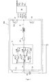
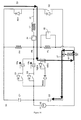
- the drive circuit 20a comprises a first voltage rail V 0 and a second voltage rail V 1 .
- the first voltage rail V 0 is at a higher voltage than the second voltage rail V 1 .
- the drive circuit 20a also includes a half-H-bridge circuit having a middle current path 32 which serves as a bi-directional current path.
- the middle current path 32 has an inductor L 1 coupled in series with a bank 10 of fuel injectors 12a, 12b.
- the fuel injectors 12a, 12b and their associated switching circuitry are connected in parallel with each other.
- Each fuel injector 12a, 12b has the electrical characteristics of a capacitor, with its piezoelectric actuator 11 being chargeable to hold voltage which is the potential difference between a low side (+) terminal and a high side (-) terminal of the piezoelectric actuator 11.
- the drive circuit 20a further comprises the first storage capacitor C 1 , and the second storage capacitor C 2 .
- Each of the storage capacitors C 1 , C 2 has a positive and a negative terminal.
- Each storage capacitor C 1 , C 2 has a high side and a low side; the high side is on the positive terminal of the capacitor and the low side is on the negative terminal.
- the first storage capacitor C 1 is connected between the first voltage rail V 0 and the second voltage rail V 1 .
- the second storage capacitor C 2 is connected between the second voltage rail V 1 and the ground potential V GND .
- the drive circuit 20a has a voltage source V S , or power supply, 22 supplied by the ECU 14.
- the voltage source V S is connected between the second voltage rail V 1 and the ground potential V GND , and is thus arranged to supply energy to the second storage capacitor C 2 .
- the voltage source V S is between 50 and 60 Volts.
- the drive circuit 20a does not have a dedicated power supply to supply charge to the first and second storage capacitors C 1 , C 2 .
- the second storage capacitor C 2 is connected to the power supply 22, but the first storage capacitor C 1 relies on regeneration of charge to it during the regeneration phase.
- the drive circuit 20a there is a charge switch Q 1 and a discharge switch Q 2 for controlling, respectively, the charging and discharging operations of the first and second fuel injectors 12a, 12b.
- the charge and the discharge switches Q 1 , Q 2 are operable by the microprocessor 16.
- Each of the charge and the discharge switches Q 1 , Q 2 when closed, allows for unidirectional current flow through the switch and, when open, prevents current flow.
- the charge switch Q 1 has a first recirculation diode RD 1 , connected across it.
- the discharge switch Q 2 has a second recirculation diode RD 2 connected across it.
- recirculation diodes RD 1 , RD 2 permit recirculation current to return charge to the first storage capacitor C 1 and the second storage capacitor C 2 , respectively, during an energy recirculation phase of operation of the drive circuit 20a, in which energy is recovered from at least one of the fuel injectors 12a, 12b.
- the first fuel injector 12a is connected in series with an associated first selector switch SQ 1
- the second fuel injector 12b is connected in series with an associated second selector switch SQ 2 .
- Each of the selector switches SQ 1 , SQ 2 is operable by the microprocessor 16.
- a first diode D 1 is connected in parallel with the first selector switch SQ 1
- a second diode D 2 is connected in parallel with the second selector switch SQ 2 .
- a current I DISCHARGE is permitted to flow in a discharge direction through the selected fuel injector 12a.
- the first and second diodes D 1 , D 2 each allow a current I CHARGE to flow in a charge direction during the charging phase of operation of the circuit, across the first and the second fuel injectors 12a, 12b, respectively.
- a regeneration switch circuitry is included in the drive circuit 20a in parallel with the injectors 12a, 12b to implement the regeneration phase.
- the regeneration switch circuitry serves to connect the second storage capacitor C 2 to the inductor L 1 .
- the regeneration switch circuitry comprises a regeneration switch RSQ which is operable by the microprocessor 16.
- a first regeneration switch diode RSD 1 is connected in parallel with the regeneration switch RSQ.
- a second regeneration switch diode RSD 2 is coupled in series to the first regeneration switch diode RSD 1 , and the regeneration switch RSQ, and acts as a protection diode.
- the first and second regeneration switch diodes RSD 1 , RSD 2 are opposed to each other such that current will not flow through the regeneration switch circuitry unless the regeneration switch RSQ is closed and current is flowing from the second voltage rail V 1 . Current, thus, cannot pass through the regeneration switch circuitry during the charging phase.
- the middle current path 32 includes a current sensing and control means 34 that arranged to communicate with the microprocessor 16.
- the current sensing and control means 34 is arranged to sense the current in the middle current path 32, to compare the sensed current with a predetermined current threshold, and to generate an output signal when the sensed current is substantially equal to the predetermined current threshold.
- a voltage sensing means V SENSE (not shown) is also provided to sense the voltage across the fuel injector 12a,12b selected for injection.
- the voltage sensing means is also used to sense the voltages V C1 , V C2 across the first and second storage capacitors C 1 , C 2 , and the power supply 22.
- the regeneration phase is terminated when sensed voltage levels V C1 , V C2 across the first and second storage capacitors C 1 , C 2 are substantially the same as predetermined voltage levels.
- the drive circuit 20a also includes control logic 30 for receiving the output of the current sensing and control means 34, the sensed voltage, V SENSE , from the positive terminal (+) of the actuators 11 of the fuel injectors 12a and 12b, and the various output signals from the microprocessor 16 and its memory 24.
- the control logic 30 includes software executable by the microprocessor 16 for processing the various inputs so as to generate control signals for each of the charge and the discharge switches Q 1 , Q 2 , the first and second selector switches SQ 1 , SQ 2 , and the regeneration switch RSQ.
- a drive pulse (or voltage waveform) is applied to the piezoelectric actuator 11 of each fuel injector 12a and 12b, for example the first fuel injector 12a.
- the drive pulse varies between the charging voltage, V CHARGE , and the discharging voltage, V DISCHARGE .
- V CHARGE the charging voltage
- V DISCHARGE the discharging voltage
- the drive pulse is at V CHARGE so that a relatively high voltage is applied to the piezoelectric actuator 11.
- V CHARGE is around 200 to 300 V.
- the drive pulse is reduced to V DISCHARGE , which is typically around -100 V.
- the voltage of the drive pulse is increased to its charging voltage level, V CHARGE , once again.
- the associated drive circuit 20a is operated in the following manner. Firstly, the discharge switch Q 2 and the first selector switch SQ 1 of the first fuel injector 12a are closed. During the discharge phase that follows, the discharge switch Q 2 is automatically opened and closed until the voltage across the selected fuel injector 12a is reduced to the appropriate voltage discharge level (i.e. V DISCHARGE ,) to initiate injection. After a predetermined time when injection is required, closing of the fuel injector 12a is achieved by closing the charge switch Q 1 , causing a charging current to flow through the first and second fuel injectors 12a and 12b.
- V DISCHARGE appropriate voltage discharge level
- the charge switch Q 1 is continually opened and closed until the appropriate charge voltage level is achieved (i.e. V CHARGE ).
- the regeneration switch RSQ is activated, and the discharge switch Q 2 is periodically opened and closed under the control of a signal emitted by the microprocessor 16 until the energy on the first storage capacitor C 1 reaches a predetermined level.
- the regeneration phase follows the charging phase at the end of an injection event.
- the regeneration switch RSQ (which has remained deactivated during the charging and discharge phases) is activated, and the discharge switch Q 2 is opened, and closed, under the control of a modulated signal from the microprocessor 16, until the energy on the first storage capacitor C 1 reaches a predetermined level.
- Faults such as short circuits and open circuit faults associated with the fuel injectors 12a, 12b in the drive circuit 20a have detectable fault response characteristics. These fault response characteristics are critical failure modes of a drive circuit and its associated bank. Such a fault present in the drive circuit 20a may affect the performance of the injector arrangement and may be critical, ultimately, to the performance of the engine 8. Although the aforementioned drive circuit 20a and its associated injectors 12a, 12b have already been developed, a suitable diagnostic tool and a suitable diagnostic method to detect these fault response characteristics has been, until now, unknown.
- the drive circuit 20a is provided with an integral diagnostic tool.
- the diagnostic tool provides a robust diagnostic system that is operated according to specific diagnostic methods to detect critical failure modes of the drive circuit 20a, and its associated piezoelectric fuel injectors 12a, 12b, thereby preventing complete failure of the drive circuit 20a and the fuel injectors 12a, 12b.
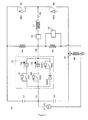
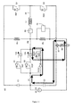
- the diagnostic tool may be embodied, in general, in two different forms, both of which are shown in Figure 3 .
- the first embodiment of the diagnostic tool is a resistive bias network comprising a first resistor R H and a second resistor R L .
- the first resistor R H is connected between the first voltage rail V 0 and the high side of the fuel injectors 12a, 12b at a bias point P B that is connected to the inductor L 1 .
- the second resistor R L is also connected to the high side of the fuel injectors 12a, 12b, at the bias point P B , and to the ground potential V GND .
- the first and second resistors R L and R H each have a known resistance of a high order of magnitude.
- a volt sensor 25 is connected across the second resistor R L and provides an output to the microprocessor 16.
- the microprocessor 16 is arranged to operate the volt sensor 25 and receives signals from the volt sensor 25 indicative of a bias voltage across the second resistor R L .
- a fault trip resistor R F in the connection of the drive circuit 20a to the ground potential V GND .
- a current sensor 27 is connected in series with the fault trip resistor R F in order to sense the current that passes through the fault trip resistor R F .
- the fault trip resistor R F is of very low resistance with an order of magnitude of milliohms.
- the microprocessor 16 is arranged to transmit control signals to the current sensor 27 and receives signals from the current sensor 27 indicative of the current flow through the fault trip resistor R F .
- the fault trip resistor R F is in series with the ground potential V GND that is connected to all of the banks in an injector arrangement, only one fault trip resistor R F is required.
- the fault trip circuit if a failure of the drive circuit 20a or the bank 10 is detected, it will only be possible in some circumstances to determine that there is a fault in the injector arrangement. It will not be possible to determine with which fuel injector 12a, 12b the fault is associated. Indeed, if the injector arrangement has more than one bank 10, it may not be possible in some circumstances to determine with which bank 10 the fault is associated.
- the charges on the piezoelectric actuators 11 of the associated fuel injectors 12a, 12b of the bank 10 are accurately predictable at any point during an injection cycle. Therefore, for faults in a drive circuit 20a that occur whilst the drive circuit 20a is in operation, the charges on the piezoelectric actuators 11 of the fuel injectors 12a, 12b are generally, known. However, at start-up the charges on the piezoelectric actuators 11 are not known. Therefore, it is necessary to test for faults at start up using a different method from that used when the bank 10 is in operation.
- the two embodiments of the diagnostic tool i.e.
- the resistive bias network with its resistors R H , R L , and the fault trip circuit with its fault trip resistor R F ) enable both types of fault to be detected, one being used whilst the drive circuit 20a and its associated bank 10 is in operation, and the other being used when the drive circuit 20a and the bank 10 are at start-up.
- the detected voltage at the bias point P B relative to the ground potential V GND , across the second resistor R L is equal to a measured bias voltage V BIAS.
- the measured bias voltage V BIAS is substantially the same as the predetermined bias voltage V Bcalc . If there is a short circuit fault associated with any of the fuel injectors 12a, 12b in the particular bank 10, the measured bias voltage V BIAS at the bias point P B will not be the predetermined bias voltage V Bcalc .
- the value of the measured bias voltage V BIAS is used to determine the nature of the short circuit fault.
- the measured bias voltage V BIAS is around the voltage of the second voltage rail V 1 , it is sometimes not possible to accurately to determine whether the short circuit fault is a short circuit between the terminals of the actuator 11 of one of the fuel injectors 12a, 12b, or a short circuit from the high side of an actuator 11 to the ground potential V GND .
- the range of measured bias voltages V BIAS which are within a tolerance voltage V Btol , either side of the predetermined bias voltage V Bcalc , is not considered to indicate a short circuit fault because, at each of these measured bias voltage V BIAS , the piezoelectric actuator 11 is sufficiently charged to operate its associated fuel injector 12a, 12b.
- the tolerance voltage V Btol is within 10 Volts of the predetermined bias voltage V Bcalc .
- the measured bias voltage V BIAS increases to a predicted selected injector voltage V PinjN , that is substantially equal to the sum of the voltage of the second voltage rail V 1 and the voltage across the selected injector V injN .
- the associated selector switch SQ 1 is opened and the measured bias voltage V BIAS exponentially decays to a voltage level set by the resistive bias network (i.e. the first and second resistors R H , R L ). Where the measured bias voltage V BIAS decay is achieved rapidly, the circuit is arranged to have a time constant that minimises the exponential decay.
- the measured bias voltage V BIAS should account for this exponential decay. Thus, for a time period after the deselection of the first fuel injector 12a, the measured bias voltage V BIAS will be greater than would normally be expected. Also, if the measurement is taken shortly after opening the selector switch SQ 1 associated with the selected fuel injector 12a, the measured bias voltage V BIAS decreases. If a short circuit is not present in the drive circuit 20a, the measured bias voltage V BIAS decreases towards the predetermined bias voltage V Bcalc . To avoid a varying measured bias voltage V BIAS , the measurement is taken after a predetermined time period. Alternatively, if the time constant of the exponential decay of the measured bias voltage V BIAS is known, this is accounted for by having a predetermined bias voltage V Bcalc that is time dependent, decreasing from the predicted selected injector voltage V PinjN .
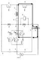
- FIG. 4 shows an arrangement of the drive circuit 20a when testing for an open circuit fault having selected the second fuel injector12b.
- the measured bias voltage V BIAS is again determined with all the switches (Q 1 , Q 2 , SQ 1 , SQ 2 , and RSQ) in the drive circuit 20a are open, with the exception of the second selector switch SQ 2 that is associated with the selected, second fuel injector 12b.
- the measured bias voltage V BIAS is substantially equal to the predicted selected injector voltage V PinjN . If the selected fuel injector 12b has an open circuit fault, the measured bias voltage V BIAS is the voltage of the first voltage rail V 0 as apportioned across the second resistor R L , when the voltage of the first voltage rail V 0 is applied across the first and second resistors R H , R L in series. The measured bias voltage V BIAS is accepted when it is within the tolerance voltage V Btol of the predicted selected injector voltage V P inj N .
- the diagnostic tests, or methods, for short and open circuit faults using the resistive bias network are carried out during normal running conditions at discrete points during the injection cycle.
- the drive pulse (the voltage across the fuel injector) is increased to the charge voltage level, V CHARGE , as shown in a first period 70.
- the bank then undergoes the regeneration phase in a second period 72.
- all other activity on the bank 10, including the regeneration phase is stopped at a point A at the beginning of a third period 74.
- the preferred diagnostic method of testing using the resistive bias network whilst the bank 10 is in operation has a number of steps which are carried out during the third period 74 of the injection cycle.
- the diagnostic method of operating the resistive bias network will now be described in more detail.
- a first step 80 all activity on the bank 10 is ceased, and all the switches (Q 1 , Q 2 , SQ 1 , SQ 2 and RSQ) are open.
- a second step 82 the voltage at the bias point P B is measured, without having closed one of the selector switches SQ 1 , SQ 2 . Thus, none of the fuel injectors 12a, 12b are selected.
- the measured bias voltage V BIAS is assessed to determine if it is within the tolerance voltage V Btol of the predetermined bias voltage V Bcalc .
- a fourth step 86 if the measured bias voltage V BIAS is outside the tolerance voltage V Btol of the predetermined bias voltage V Bcalc , a short circuit is present in the bank 10, and a short circuit fault response is initiated.
- the fuel injector that is next to inject in the bank 10 in the injection cycle is tested for an open circuit fault. The fuel injector that is next to inject is selected by closing the selector switch SQ 1 , SQ 2 associated with the fuel injector, as described previously.
- the measured bias voltage V BIAS is assessed in a fifth step 88 to determine if it is within the tolerance voltage V Btol of the predicted selected injector voltage V PinjN .
- a sixth step 90 if the difference between the measured bias voltage V BIAS and the predicted selected injector voltage V PinjN is more than the voltage tolerance V Btol , an open circuit fault in the bank is detected, and an open circuit fault response is initiated.
- a seventh step 92 if a fault is not detected on the bank 10, injection is enabled.
- the microprocessor 16 is configured to implement the method described above with reference to Figure 6 whilst the drive circuit 20a and the bank 10 are in operation.
- the method is embodied in a computer program, or a series of computer programs, stored in the memory 24 of the microprocessor 16 and executed by the microprocessor 16 to implement the method.
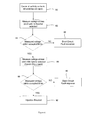
- the diagnostic method of testing using the resistive bias network whilst the bank is in operation is adapted for use at start-up.
- the charge switch Q 1 is closed for a predetermined time.
- a second step 102 all the switches (Q 1 , Q 2 , SQ 1 , SQ 2 and RSQ) are opened and the voltage at the bias point P B is measured in order to detect short circuit faults in the drive circuit 20a.
- a third step 104 the measured bias voltage V BIAS is assessed to determine if it is within the tolerance voltage V Btol of the predetermined bias voltage V Bcalc .
- a fourth step 106 if the measured bias voltage V BIAS is outside the tolerance voltage V Btol of the predetermined bias voltage V Bcalc , a short circuit fault is detected in the drive circuit 20a, and a short circuit fault response is initiated. Alternatively, if the measured bias voltage V BIAS is within the tolerance voltage V Btol of the predetermined bias voltage V Bcalc , no short circuit is detected.
- a fifth step 108 the charge switch Q 1 is re-closed for a calibrated time period in order to detect an open circuit fault in the drive circuit 20a.
- a sixth step 110 the voltage at the bias point P B is measured, with one of the selector switches closed, for example the first selector switch SQ 1 in order to select the first fuel injector 12a.
- the measured bias voltage V BIAS is assessed to determine if it is within the tolerance voltage V Btol of the predicted selected injector voltage V PinjN .
- an open circuit fault is detected that is associated with the selected fuel injector 12a, 12b, and an open circuit fault response is initiated; otherwise an open circuit fault has not been detected.
- the method proceeds to the ninth step 116 in which the method returns to the sixth step 110 to test another of the fuel injectors 12a, 12b on the bank 10, for example the second fuel injector 12b.
- the sixth to the ninth steps 110, 112, 114, 116 are repeated until all the fuel injectors 12a, 12b on the bank 10 have been tested for an open circuit fault.
- the method proceeds to a tenth step 118 in which other activity is enabled on the bank 10.
- the microprocessor 16 is configured to implement the method at start-up of the drive circuit 20a, using the resistive bias network as described above with reference to Figure 7 .
- the method is embodied in a computer program, or a series of computer programs, stored in the memory 24 of the microprocessor 16 and executed by the microprocessor 16 to implement the method.
- the current through the fault trip resistor R F is monitored by the current sensor 27 that is operable by the microprocessor 16.
- the circuit is arranged to trip, and the microprocessor 16 is arranged to initiate a signal.
- the drive circuit 20a is arranged to trip if one of the fuel injectors 12a, 12b has a low side, or a high side, short circuit fault to the ground potential V GND at any time when any of the switches (Q 1 , Q 2 , SQ 1 , SQ 2 and RSQ) are closed.
- a number of arrangements of the switches (Q 1 , Q 2 , SQ 1 , SQ 2 and RSQ) in the drive circuit 20a will now be described in detail with reference to Figures 8 to 11 . In all these arrangements all of the switches (Q 1 , Q 2 , SQ 1 , SQ 2 and RSQ) are open, unless specifically mentioned. Also, note that each of these figures has a bold line that represents the path in the drive circuit 20a taken by the short circuit current.
- the corresponding figures show the short circuit affecting the second fuel injector 12b.
- the short circuit might equally be located in the first fuel injector 12a, or any other fuel injector present in the bank 10.
- the fault trip circuit By operating the fault trip circuit, it is not possible to determine with which fuel injector of the bank 10 the fault is associated, because only one fault trip resistor R F is present in the drive circuit 20a.
- the fault trip circuit can detect the presence of a short circuit fault in the injector arrangement but cannot be used to identify the fuel injector 12a, 12b, or even the specific bank, with which the fault is associated.
- the regeneration switch RSQ is closed, and all the other switches (Q 1 , Q 2 , SQ 1 and SQ 2 ) of the drive circuit 20a are open.
- a high side to ground potential V GND short circuit fault that is associated with the second fuel injector 12b is detectable.
- a low side to ground potential V GND short circuit fault that is associated with the second fuel injector 12b is detectable.
- the short circuit fault shown in Figure 13 is only detectable if there is no, or negligible, charge on the selected, second fuel injector 12b.
- an injector arrangement comprising more than one bank
- one of the banks comprises more than one fuel injector 12a, 12b
- the fault trip circuit may be tripped deliberately at start-up.
- the circuitry of the fault trip circuit is tripped deliberately at start-up by operating the regeneration switch RSQ of a bank 10, or the discharge switch Q 2 of the associated drive circuit 20a, as shown in Figures 8 , 12 and 13 .
- the fault trip circuit is used in preference to the resistive bias network at start-up because the resistive bias network is less reliable at start-up than the fault trip circuit due to the possibility of unknown voltages being present across the fuel injectors 12a, 12b.
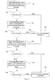
- Figure 14 shows, in the form of a flow diagram, the steps of the method used to trip the fault trip circuit deliberately when applied to an injector arrangement comprising at least two banks: the first bank 10, and a second bank 10b. If the injector arrangement comprises more than two banks, the same steps that are applied to each of the first two banks 10, 10b are then applied to the third and further banks, 10c to10 N , in turn.
- the regeneration switch RSQ is closed on the first bank 10 of the injector arrangement for a predetermined period of time.
- a second step 122 the current flowing through the fault trip resistor R F is monitored in order to measure the detected current I dect .
- a short circuit fault response is initiated.
- the testing of the first bank 10 is now complete, and the method proceeds directly to a sixth step 130.
- the discharge switch Q 2 of the first bank 10 is closed for a predetermined amount of time.
- a fourth step 126 the current passing through the fault trip resistor R F is monitored in order to measure the detected current I dect .
- a short circuit fault response is initiated.
- the testing of the first bank 10 is now complete.
- the method continues by testing the second bank 10b.
- the regeneration switch RSQ of the second bank 10b is closed for a predetermined amount of time.
- a seventh step 132 the current passing through the fault trip resistor R F is monitored to measure the detected current I dect .
- step 134 if the detected current I dect is in excess of the threshold current I trip , a short circuit fault response is initiated and the testing of the second bank 10b is complete.
- the injector arrangement is now ready for start-up.
- the discharge switch Q 2 of the second bank 10b is closed for a predetermined amount of time.
- a ninth step 136 the current passing through the fault trip resistor R F is monitored to measure the detected current I dect .
- a short circuit fault response is initiated.
- the microprocessor 16 is configured to implement the diagnostic methods of testing the drive circuit 20a using the fault trip circuit at start-up, and during normal running conditions of the drive circuit 20a.
- the method is embodied in a computer program, or a series of computer programs, stored in the memory 24 of the microprocessor 16 and executed by the microprocessor 16 to implement these methods.
- both the fault trip circuit and the bias network are present in the drive circuit 20a. They are used independently to detect short circuits, but only the bias network is capable of being used to detect open circuit faults. These two diagnostic tools are, thus, complementary.
- the resistive bias network can be used to identify with which bank 10, 10b the short circuit is associated, because there is a bias network integrated into each drive circuit 20a, 20b.
- the bank 10, 10b is identified by applying to each of the drive circuits 20a, 20b the diagnostic method in which the bias network is used.
- the steps of the diagnostic method in which the resistive bias network is used to detect open circuit faults may be combined with the diagnostic method in which the fault trip circuit is used.
- the combined diagnostic method can therefore detect reliably both short and open circuit faults at start-up.
- an injector arrangement that has at least two banks 10, 10b (each having an associated drive circuit 20a, 20b) it is preferable to apply the diagnostic method in which the fault trip circuit is used, instead of the bias network.
- the diagnostic method in which the bias network is used is limited in its performance by the presence of an unknown voltage across each of the fuel injectors 12a, 12b.
- the diagnostic method in which the resistive bias network is used is applied to each of the drive circuits 20a, 20b of the injector arrangement after the diagnostic method using the fault trip circuit has been applied.
- the diagnostic methods in which the resistive bias network is used are capable of detecting both short and open circuit faults. These methods may be used to detect these two types of fault separately, instead of together as described for the preferred embodiment.
- the resistive biasing network may be adapted to test only for short circuit faults or only for open circuit faults.
- Only one of the two aforementioned diagnostic tools, the resistive bias network and the fault trip circuit, may be included in the drive circuit 20a.
- the drive circuit 20a herein described is a generic drive circuit.
- the resistive bias network and fault trip circuit may be adapted for use with similar drive circuits which obviate the need for a dedicated power supply, for example, the drive circuits described in WO 2005/028836 .
- drive circuit may be used with each of the diagnostic tools.
- the drive circuit may only have one voltage rail, or it may not have the circuitry that is used in the regeneration phase.
- the drive circuit 20a is integrated within the ECM 14. In another embodiment, however, the drive circuit 20a is separate from, but connected to, the rest of the ECM 14.
- the fuel injectors 12a, 12b are of a negative-charge displacement type.
- the fuel injectors 12a, 12b are of a positive-charge displacement type, in which case the drive circuits 20a are configured with the fuel injectors 12a, 12b so that the fuel injectors 12a, 12b are open to inject fuel during a charging phase and are closed to terminate fuel injection during a discharge phase.
- the method of operating the fault trip circuit at start up is applied to each of the banks of the injector arrangement. After the first two banks 10, 10b have been tested, the method is repeated from the sixth step 130 to the tenth step 138, inclusive, on each of the third and further banks 10c to 10 N.
- the fault trip resistor R F operates as the current sensor 27.
- the diagnostic methods that test the drive circuit 20a for short circuit faults to the ground potential V GND are also capable of detecting equivalent short circuits to the voltage V BAT of the engine battery.
- the tolerance voltage may be any value so that the measured bias voltage is sufficient to operate the fuel injector 12a, 12b concerned.
- the tolerance voltage may be between 5 and 20 Volts.
- each bank has a current sensor 27.
- each bank has a current sensor 27.
- the plurality of current sensors 27 it would be possible using the plurality of current sensors 27 to determine with which bank a detected short circuit fault is associated, because the fault is only detectable by the current sensor 27 of the bank associated with the fault.
- a bank may have a plurality of injectors 12a to 12 N , with a corresponding number of selector switches SQ 1 to SQ N .
Landscapes
- Engineering & Computer Science (AREA)
- Chemical & Material Sciences (AREA)
- Combustion & Propulsion (AREA)
- Mechanical Engineering (AREA)
- General Engineering & Computer Science (AREA)
- Electrical Control Of Air Or Fuel Supplied To Internal-Combustion Engine (AREA)
- Fuel-Injection Apparatus (AREA)
Priority Applications (1)
| Application Number | Priority Date | Filing Date | Title |
|---|---|---|---|
| EP11191576.5A EP2428670B1 (de) | 2006-04-03 | 2006-04-03 | Treiberschaltung für eine Einspritzventilanordnung |
Applications Claiming Priority (2)
| Application Number | Priority Date | Filing Date | Title |
|---|---|---|---|
| EP11191576.5A EP2428670B1 (de) | 2006-04-03 | 2006-04-03 | Treiberschaltung für eine Einspritzventilanordnung |
| EP06251881.6A EP1843027B1 (de) | 2006-04-03 | 2006-04-03 | Treiberschaltung für eine Einspritzventilanordnung und Diagnosemethode |
Related Parent Applications (3)
| Application Number | Title | Priority Date | Filing Date |
|---|---|---|---|
| EP06251881.6A Division EP1843027B1 (de) | 2006-04-03 | 2006-04-03 | Treiberschaltung für eine Einspritzventilanordnung und Diagnosemethode |
| EP06251881.6A Division-Into EP1843027B1 (de) | 2006-04-03 | 2006-04-03 | Treiberschaltung für eine Einspritzventilanordnung und Diagnosemethode |
| EP06251881.6 Division | 2006-04-03 |
Publications (2)
| Publication Number | Publication Date |
|---|---|
| EP2428670A1 true EP2428670A1 (de) | 2012-03-14 |
| EP2428670B1 EP2428670B1 (de) | 2021-06-09 |
Family
ID=36729823
Family Applications (2)
| Application Number | Title | Priority Date | Filing Date |
|---|---|---|---|
| EP11191576.5A Active EP2428670B1 (de) | 2006-04-03 | 2006-04-03 | Treiberschaltung für eine Einspritzventilanordnung |
| EP06251881.6A Active EP1843027B1 (de) | 2006-04-03 | 2006-04-03 | Treiberschaltung für eine Einspritzventilanordnung und Diagnosemethode |
Family Applications After (1)
| Application Number | Title | Priority Date | Filing Date |
|---|---|---|---|
| EP06251881.6A Active EP1843027B1 (de) | 2006-04-03 | 2006-04-03 | Treiberschaltung für eine Einspritzventilanordnung und Diagnosemethode |
Country Status (3)
| Country | Link |
|---|---|
| US (1) | US7640918B2 (de) |
| EP (2) | EP2428670B1 (de) |
| JP (2) | JP4741543B2 (de) |
Families Citing this family (40)
| Publication number | Priority date | Publication date | Assignee | Title |
|---|---|---|---|---|
| US7400477B2 (en) | 1998-08-24 | 2008-07-15 | Leviton Manufacturing Co., Inc. | Method of distribution of a circuit interrupting device with reset lockout and reverse wiring protection |
| US7852606B2 (en) * | 2005-08-24 | 2010-12-14 | Leviton Manufacturing Company, Inc. | Self-testing circuit interrupting device |
| US7372678B2 (en) | 2005-08-24 | 2008-05-13 | Leviton Manufacturing Co., Inc. | Circuit interrupting device with automatic test |
| GB0610226D0 (en) * | 2006-05-23 | 2006-07-05 | Delphi Tech Inc | Drive circuit for an injector arrangement and a diagnostic method |
| US7911746B2 (en) * | 2006-06-01 | 2011-03-22 | Leviton Manufacturing Co., Inc. | GFCI with self-test and remote annunciation capabilities |
| EP1927743A1 (de) * | 2006-11-30 | 2008-06-04 | Delphi Technologies, Inc. | Fehlerdetektion in einer Injektoranordnung |
| DE102007014330A1 (de) * | 2007-03-26 | 2008-10-02 | Robert Bosch Gmbh | Ansteuerschaltung und Ansteuerverfahren für ein piezoelektrisches Element |
| DE102007023898A1 (de) * | 2007-05-23 | 2008-11-27 | Robert Bosch Gmbh | Verfahren zum Ansteuern eines Einspritzventils |
| DE102007026946B4 (de) * | 2007-06-12 | 2009-06-04 | Continental Automotive Gmbh | Verfahren und Vorrichtung zum Betreiben eines Einspritzventils, Computerprogramm und Einspritzventil |
| ATE531919T1 (de) * | 2007-06-22 | 2011-11-15 | Delphi Tech Holding Sarl | Fehlerdetektion in einer injektoranordnung |
| JP4469886B2 (ja) * | 2007-09-20 | 2010-06-02 | 日立オートモティブシステムズ株式会社 | 負荷駆動回路 |
| EP2048343A1 (de) | 2007-10-11 | 2009-04-15 | Delphi Technologies, Inc. | Fehlererkennung in einer Injektoranordnung |
| DE602007011945D1 (de) | 2007-11-09 | 2011-02-24 | Delphi Technologies Holding | Fehlerdetektion in einer Injektoranordnung |
| CN101910856B (zh) | 2008-01-29 | 2014-06-18 | 立维腾制造有限公司 | 自测试故障电路中断器装置和方法 |
| GB0807854D0 (en) * | 2008-04-30 | 2008-06-04 | Delphi Tech Inc | Detection of faults in an injector arrangement |
| DE102008001571A1 (de) * | 2008-05-06 | 2009-11-12 | Robert Bosch Gmbh | Verfahren und Vorrichtung zur Überwachung eines Piezoaktors |
| US8183869B2 (en) * | 2008-09-23 | 2012-05-22 | Leviton Manufacturing Co., Inc. | Circuit interrupter with continuous self-testing feature |
| DE102008042981A1 (de) * | 2008-10-21 | 2010-04-22 | Robert Bosch Gmbh | Verfahren und Steuervorrichtung zur Ansteuerung eines Kraftstoffinjektors |
| DE102008054512B4 (de) * | 2008-12-11 | 2021-08-05 | Robert Bosch Gmbh | Verfahren zum Betreiben eines Kraftstoffeinspritzsystems einer Brennkraftmaschine |
| US8161946B2 (en) * | 2009-11-20 | 2012-04-24 | Ford Global Technologies, Llc | Fuel injector interface and diagnostics |
| GB2476105A (en) * | 2009-12-14 | 2011-06-15 | Gm Global Tech Operations Inc | Fault management in an i.c. engine piezoelectric fuel injection system |
| FR2955516B1 (fr) * | 2010-01-26 | 2012-04-20 | Prospection & Inventions | Procede de commande d'un outil a moteur a combustion interne et l'outil ainsi commande |
| US8813723B2 (en) * | 2011-05-20 | 2014-08-26 | GM Global Technology Operations LLC | System and method for detecting a stuck fuel injector |
| CN103748353B (zh) * | 2011-09-02 | 2016-04-13 | 丰田自动车株式会社 | 内燃机的燃料供给装置 |
| US9048775B2 (en) | 2012-10-30 | 2015-06-02 | National Instruments Corporation | H-bridge for combined solenoid and piezo injection control |
| US9611797B2 (en) * | 2012-10-30 | 2017-04-04 | National Instruments Corporation | Direct injection flexible multiplexing scheme |
| KR101567165B1 (ko) * | 2013-12-19 | 2015-11-09 | 현대자동차주식회사 | 인젝터 드라이버 |
| US9708998B2 (en) | 2014-04-01 | 2017-07-18 | GM Global Technology Operations LLC | System and method for improving fuel delivery accuracy by detecting and compensating for fuel injector characteristics |
| US9683510B2 (en) | 2014-04-01 | 2017-06-20 | GM Global Technology Operations LLC | System and method for improving fuel delivery accuracy by learning and compensating for fuel injector characteristics |
| US9458789B2 (en) * | 2014-04-01 | 2016-10-04 | GM Global Technology Operations LLC | Missed fuel injection diagnostic systems and methods |
| US9435289B2 (en) * | 2014-04-01 | 2016-09-06 | GM Global Technology Operations LLC | Systems and methods for minimizing throughput |
| US9759758B2 (en) | 2014-04-25 | 2017-09-12 | Leviton Manufacturing Co., Inc. | Ground fault detector |
| WO2015174310A1 (ja) * | 2014-05-13 | 2015-11-19 | 日立オートモティブシステムズ株式会社 | 内燃機関の燃料噴射装置 |
| DE102015214780A1 (de) * | 2015-08-03 | 2017-02-09 | Continental Automotive Gmbh | Verfahren zur Erkennung fehlerhafter Komponenten eines Kraftstoffeinspritzsystems |
| CN105569859B (zh) * | 2015-12-14 | 2018-08-28 | 中国北方发动机研究所(天津) | 具有升压和故障诊断功能的高速电磁阀驱动方法及电路 |
| JP6555287B2 (ja) | 2017-03-03 | 2019-08-07 | トヨタ自動車株式会社 | 内燃機関の燃料噴射制御装置 |
| JP6970823B2 (ja) * | 2018-05-23 | 2021-11-24 | 日立Astemo株式会社 | 燃料噴射制御装置 |
| FR3082315B1 (fr) * | 2018-06-11 | 2020-05-15 | Continental Automotive France | Procede de detection d'un dysfonctionnement d'un circuit limiteur de tension et systeme de controle pour la mise en œuvre dudit procede de detection de dysfonctionnement |
| CN112628453B (zh) * | 2020-12-29 | 2023-03-21 | 潍柴动力股份有限公司 | 电磁阀故障诊断方法、装置及燃气发动机 |
| CN115387923B (zh) * | 2022-09-15 | 2023-09-12 | 一汽解放汽车有限公司 | 发动机的喷射器的故障检测方法、装置、设备及介质 |
Citations (7)
| Publication number | Priority date | Publication date | Assignee | Title |
|---|---|---|---|---|
| US6212053B1 (en) * | 1997-06-06 | 2001-04-03 | Siemens Aktiengesellschaft | Device and method for driving at least one capacitive actuator |
| EP1139442A1 (de) * | 2000-04-01 | 2001-10-04 | Robert Bosch GmbH | Vorrichtung und Verfahren zur Kurzschlusserkennung zum Batteriespannung eines piezoelektrischen Antriebs |
| US20010039484A1 (en) * | 1998-09-30 | 2001-11-08 | Hellmut Freudenberg | Method and configuration for diagnosis of a capacitive actuator |
| US6472796B1 (en) * | 1998-06-25 | 2002-10-29 | Siemens Aktiengesellschaft | Method and apparatus for controlling a capacitive actuator |
| EP1400676A2 (de) | 2002-09-23 | 2004-03-24 | Delphi Technologies, Inc. | Treiberschaltung für eine Kraftstoff-Einspritzdüse |
| WO2005028836A1 (en) | 2003-09-23 | 2005-03-31 | Delphi Technologies, Inc. | A drive circuit for an injector arrangement |
| US20060067024A1 (en) * | 2002-12-03 | 2006-03-30 | Eric Chemisky | Monitoring method for an actuator and corresponding driver circuit |
Family Cites Families (11)
| Publication number | Priority date | Publication date | Assignee | Title |
|---|---|---|---|---|
| GB2306679B (en) * | 1995-11-03 | 2000-05-17 | Motorola Ltd | Method for detecting closure of a solenoid coil |
| DE19632837A1 (de) * | 1996-08-14 | 1998-02-19 | Siemens Ag | Vorrichtung und Verfahren zum Ansteuern wenigstens eines kapazitiven Stellgliedes |
| DE19804196A1 (de) * | 1998-02-03 | 1999-08-12 | Siemens Ag | Verfahren zur Auswertung von Kennwerten piezo-mechanischer Systeme |
| US6560528B1 (en) * | 2000-03-24 | 2003-05-06 | Internal Combustion Technologies, Inc. | Programmable internal combustion engine controller |
| DE10016476A1 (de) * | 2000-04-01 | 2001-12-06 | Bosch Gmbh Robert | Verfahren zur Diagnose der Spannungsansteuerung für einen piezoelektrischen Aktor eines Einspritzventils |
| JP4456285B2 (ja) * | 2001-02-05 | 2010-04-28 | 本田技研工業株式会社 | 燃料噴射弁駆動装置 |
| JP2002246667A (ja) * | 2001-02-13 | 2002-08-30 | Denso Corp | ピエゾアクチュエータ駆動回路および燃料噴射装置 |
| US6923161B2 (en) * | 2002-03-28 | 2005-08-02 | Siemens Vdo Automotive Corporation | Fuel injection timer and current regulator |
| US6760212B2 (en) * | 2002-09-23 | 2004-07-06 | Delphi Technologies, Inc. | Piezoelectric injector drive circuit |
| ITBO20030642A1 (it) * | 2003-10-31 | 2005-05-01 | Magneti Marelli Powertrain Spa | Metodo per il pilotaggio di un iniettore con verifica |
| DE102004021377A1 (de) * | 2004-04-30 | 2005-11-17 | Robert Bosch Gmbh | Verfahren zur Diagnose einer Ansteuerschaltung |
-
2006
- 2006-04-03 EP EP11191576.5A patent/EP2428670B1/de active Active
- 2006-04-03 EP EP06251881.6A patent/EP1843027B1/de active Active
-
2007
- 2007-04-03 US US11/732,295 patent/US7640918B2/en active Active
- 2007-04-03 JP JP2007097118A patent/JP4741543B2/ja active Active
-
2010
- 2010-12-08 JP JP2010273757A patent/JP5400018B2/ja active Active
Patent Citations (7)
| Publication number | Priority date | Publication date | Assignee | Title |
|---|---|---|---|---|
| US6212053B1 (en) * | 1997-06-06 | 2001-04-03 | Siemens Aktiengesellschaft | Device and method for driving at least one capacitive actuator |
| US6472796B1 (en) * | 1998-06-25 | 2002-10-29 | Siemens Aktiengesellschaft | Method and apparatus for controlling a capacitive actuator |
| US20010039484A1 (en) * | 1998-09-30 | 2001-11-08 | Hellmut Freudenberg | Method and configuration for diagnosis of a capacitive actuator |
| EP1139442A1 (de) * | 2000-04-01 | 2001-10-04 | Robert Bosch GmbH | Vorrichtung und Verfahren zur Kurzschlusserkennung zum Batteriespannung eines piezoelektrischen Antriebs |
| EP1400676A2 (de) | 2002-09-23 | 2004-03-24 | Delphi Technologies, Inc. | Treiberschaltung für eine Kraftstoff-Einspritzdüse |
| US20060067024A1 (en) * | 2002-12-03 | 2006-03-30 | Eric Chemisky | Monitoring method for an actuator and corresponding driver circuit |
| WO2005028836A1 (en) | 2003-09-23 | 2005-03-31 | Delphi Technologies, Inc. | A drive circuit for an injector arrangement |
Also Published As
| Publication number | Publication date |
|---|---|
| EP1843027A1 (de) | 2007-10-10 |
| EP2428670B1 (de) | 2021-06-09 |
| US20070227506A1 (en) | 2007-10-04 |
| JP2007292067A (ja) | 2007-11-08 |
| EP1843027B1 (de) | 2018-12-19 |
| JP2011122592A (ja) | 2011-06-23 |
| US7640918B2 (en) | 2010-01-05 |
| JP5400018B2 (ja) | 2014-01-29 |
| JP4741543B2 (ja) | 2011-08-03 |
Similar Documents
| Publication | Publication Date | Title |
|---|---|---|
| US7640918B2 (en) | Drive circuit for an injector arrangement and a diagnostic method | |
| US7624721B2 (en) | Drive circuit for an injector arrangement and a diagnostic method | |
| EP2006518B1 (de) | Fehlerdetektion in einer Injektoranordnung | |
| US7822537B2 (en) | Detection of faults in an injector arrangement | |
| US8248074B2 (en) | Detection of faults in an injector arrangement | |
| US7966871B2 (en) | Detection of faults in an injector arrangement | |
| US8193816B2 (en) | Detection of faults in an injector arrangement | |
| US20020008440A1 (en) | Method and apparatus for timed measurement of the voltage across a device in the charging circuit of a piezoelectric element |
Legal Events
| Date | Code | Title | Description |
|---|---|---|---|
| AC | Divisional application: reference to earlier application |
Ref document number: 1843027 Country of ref document: EP Kind code of ref document: P |
|
| AK | Designated contracting states |
Kind code of ref document: A1 Designated state(s): AT BE BG CH CY CZ DE DK EE ES FI FR GB GR HU IE IS IT LI LT LU LV MC NL PL PT RO SE SI SK TR |
|
| AX | Request for extension of the european patent |
Extension state: AL BA HR MK YU |
|
| PUAI | Public reference made under article 153(3) epc to a published international application that has entered the european phase |
Free format text: ORIGINAL CODE: 0009012 |
|
| 17P | Request for examination filed |
Effective date: 20120914 |
|
| RAP1 | Party data changed (applicant data changed or rights of an application transferred) |
Owner name: DELPHI INTERNATIONAL OPERATIONS LUXEMBOURG S.A.R.L |
|
| 17Q | First examination report despatched |
Effective date: 20140320 |
|
| STAA | Information on the status of an ep patent application or granted ep patent |
Free format text: STATUS: EXAMINATION IS IN PROGRESS |
|
| RAP1 | Party data changed (applicant data changed or rights of an application transferred) |
Owner name: DELPHI TECHNOLOGIES IP LIMITED |
|
| STAA | Information on the status of an ep patent application or granted ep patent |
Free format text: STATUS: EXAMINATION IS IN PROGRESS |
|
| RIC1 | Information provided on ipc code assigned before grant |
Ipc: F02D 41/06 20060101ALN20201223BHEP Ipc: F02D 41/22 20060101ALI20201223BHEP Ipc: F02D 41/20 20060101AFI20201223BHEP |
|
| GRAP | Despatch of communication of intention to grant a patent |
Free format text: ORIGINAL CODE: EPIDOSNIGR1 |
|
| STAA | Information on the status of an ep patent application or granted ep patent |
Free format text: STATUS: GRANT OF PATENT IS INTENDED |
|
| INTG | Intention to grant announced |
Effective date: 20210205 |
|
| GRAS | Grant fee paid |
Free format text: ORIGINAL CODE: EPIDOSNIGR3 |
|
| GRAA | (expected) grant |
Free format text: ORIGINAL CODE: 0009210 |
|
| STAA | Information on the status of an ep patent application or granted ep patent |
Free format text: STATUS: THE PATENT HAS BEEN GRANTED |
|
| AC | Divisional application: reference to earlier application |
Ref document number: 1843027 Country of ref document: EP Kind code of ref document: P |
|
| AK | Designated contracting states |
Kind code of ref document: B1 Designated state(s): AT BE BG CH CY CZ DE DK EE ES FI FR GB GR HU IE IS IT LI LT LU LV MC NL PL PT RO SE SI SK TR |
|
| REG | Reference to a national code |
Ref country code: GB Ref legal event code: FG4D |
|
| REG | Reference to a national code |
Ref country code: CH Ref legal event code: EP Ref country code: AT Ref legal event code: REF Ref document number: 1400701 Country of ref document: AT Kind code of ref document: T Effective date: 20210615 |
|
| REG | Reference to a national code |
Ref country code: DE Ref legal event code: R096 Ref document number: 602006060084 Country of ref document: DE |
|
| REG | Reference to a national code |
Ref country code: IE Ref legal event code: FG4D |
|
| REG | Reference to a national code |
Ref country code: LT Ref legal event code: MG9D |
|
| PG25 | Lapsed in a contracting state [announced via postgrant information from national office to epo] |
Ref country code: BG Free format text: LAPSE BECAUSE OF FAILURE TO SUBMIT A TRANSLATION OF THE DESCRIPTION OR TO PAY THE FEE WITHIN THE PRESCRIBED TIME-LIMIT Effective date: 20210909 Ref country code: LT Free format text: LAPSE BECAUSE OF FAILURE TO SUBMIT A TRANSLATION OF THE DESCRIPTION OR TO PAY THE FEE WITHIN THE PRESCRIBED TIME-LIMIT Effective date: 20210609 Ref country code: FI Free format text: LAPSE BECAUSE OF FAILURE TO SUBMIT A TRANSLATION OF THE DESCRIPTION OR TO PAY THE FEE WITHIN THE PRESCRIBED TIME-LIMIT Effective date: 20210609 |
|
| REG | Reference to a national code |
Ref country code: AT Ref legal event code: MK05 Ref document number: 1400701 Country of ref document: AT Kind code of ref document: T Effective date: 20210609 |
|
| REG | Reference to a national code |
Ref country code: NL Ref legal event code: MP Effective date: 20210609 |
|
| PG25 | Lapsed in a contracting state [announced via postgrant information from national office to epo] |
Ref country code: GR Free format text: LAPSE BECAUSE OF FAILURE TO SUBMIT A TRANSLATION OF THE DESCRIPTION OR TO PAY THE FEE WITHIN THE PRESCRIBED TIME-LIMIT Effective date: 20210910 Ref country code: LV Free format text: LAPSE BECAUSE OF FAILURE TO SUBMIT A TRANSLATION OF THE DESCRIPTION OR TO PAY THE FEE WITHIN THE PRESCRIBED TIME-LIMIT Effective date: 20210609 Ref country code: SE Free format text: LAPSE BECAUSE OF FAILURE TO SUBMIT A TRANSLATION OF THE DESCRIPTION OR TO PAY THE FEE WITHIN THE PRESCRIBED TIME-LIMIT Effective date: 20210609 |
|
| PG25 | Lapsed in a contracting state [announced via postgrant information from national office to epo] |
Ref country code: CZ Free format text: LAPSE BECAUSE OF FAILURE TO SUBMIT A TRANSLATION OF THE DESCRIPTION OR TO PAY THE FEE WITHIN THE PRESCRIBED TIME-LIMIT Effective date: 20210609 Ref country code: EE Free format text: LAPSE BECAUSE OF FAILURE TO SUBMIT A TRANSLATION OF THE DESCRIPTION OR TO PAY THE FEE WITHIN THE PRESCRIBED TIME-LIMIT Effective date: 20210609 Ref country code: SK Free format text: LAPSE BECAUSE OF FAILURE TO SUBMIT A TRANSLATION OF THE DESCRIPTION OR TO PAY THE FEE WITHIN THE PRESCRIBED TIME-LIMIT Effective date: 20210609 Ref country code: ES Free format text: LAPSE BECAUSE OF FAILURE TO SUBMIT A TRANSLATION OF THE DESCRIPTION OR TO PAY THE FEE WITHIN THE PRESCRIBED TIME-LIMIT Effective date: 20210609 Ref country code: RO Free format text: LAPSE BECAUSE OF FAILURE TO SUBMIT A TRANSLATION OF THE DESCRIPTION OR TO PAY THE FEE WITHIN THE PRESCRIBED TIME-LIMIT Effective date: 20210609 Ref country code: PT Free format text: LAPSE BECAUSE OF FAILURE TO SUBMIT A TRANSLATION OF THE DESCRIPTION OR TO PAY THE FEE WITHIN THE PRESCRIBED TIME-LIMIT Effective date: 20211011 Ref country code: NL Free format text: LAPSE BECAUSE OF FAILURE TO SUBMIT A TRANSLATION OF THE DESCRIPTION OR TO PAY THE FEE WITHIN THE PRESCRIBED TIME-LIMIT Effective date: 20210609 Ref country code: AT Free format text: LAPSE BECAUSE OF FAILURE TO SUBMIT A TRANSLATION OF THE DESCRIPTION OR TO PAY THE FEE WITHIN THE PRESCRIBED TIME-LIMIT Effective date: 20210609 |
|
| PG25 | Lapsed in a contracting state [announced via postgrant information from national office to epo] |
Ref country code: PL Free format text: LAPSE BECAUSE OF FAILURE TO SUBMIT A TRANSLATION OF THE DESCRIPTION OR TO PAY THE FEE WITHIN THE PRESCRIBED TIME-LIMIT Effective date: 20210609 |
|
| REG | Reference to a national code |
Ref country code: DE Ref legal event code: R097 Ref document number: 602006060084 Country of ref document: DE |
|
| PLBE | No opposition filed within time limit |
Free format text: ORIGINAL CODE: 0009261 |
|
| STAA | Information on the status of an ep patent application or granted ep patent |
Free format text: STATUS: NO OPPOSITION FILED WITHIN TIME LIMIT |
|
| PG25 | Lapsed in a contracting state [announced via postgrant information from national office to epo] |
Ref country code: DK Free format text: LAPSE BECAUSE OF FAILURE TO SUBMIT A TRANSLATION OF THE DESCRIPTION OR TO PAY THE FEE WITHIN THE PRESCRIBED TIME-LIMIT Effective date: 20210609 |
|
| 26N | No opposition filed |
Effective date: 20220310 |
|
| PG25 | Lapsed in a contracting state [announced via postgrant information from national office to epo] |
Ref country code: IT Free format text: LAPSE BECAUSE OF FAILURE TO SUBMIT A TRANSLATION OF THE DESCRIPTION OR TO PAY THE FEE WITHIN THE PRESCRIBED TIME-LIMIT Effective date: 20210609 |
|
| REG | Reference to a national code |
Ref country code: CH Ref legal event code: PL |
|
| REG | Reference to a national code |
Ref country code: BE Ref legal event code: MM Effective date: 20220430 |
|
| PG25 | Lapsed in a contracting state [announced via postgrant information from national office to epo] |
Ref country code: MC Free format text: LAPSE BECAUSE OF FAILURE TO SUBMIT A TRANSLATION OF THE DESCRIPTION OR TO PAY THE FEE WITHIN THE PRESCRIBED TIME-LIMIT Effective date: 20210609 Ref country code: LU Free format text: LAPSE BECAUSE OF NON-PAYMENT OF DUE FEES Effective date: 20220403 Ref country code: LI Free format text: LAPSE BECAUSE OF NON-PAYMENT OF DUE FEES Effective date: 20220430 Ref country code: CH Free format text: LAPSE BECAUSE OF NON-PAYMENT OF DUE FEES Effective date: 20220430 |
|
| PG25 | Lapsed in a contracting state [announced via postgrant information from national office to epo] |
Ref country code: BE Free format text: LAPSE BECAUSE OF NON-PAYMENT OF DUE FEES Effective date: 20220430 |
|
| PG25 | Lapsed in a contracting state [announced via postgrant information from national office to epo] |
Ref country code: IE Free format text: LAPSE BECAUSE OF NON-PAYMENT OF DUE FEES Effective date: 20220403 |
|
| PGFP | Annual fee paid to national office [announced via postgrant information from national office to epo] |
Ref country code: FR Payment date: 20230320 Year of fee payment: 18 |
|
| P01 | Opt-out of the competence of the unified patent court (upc) registered |
Effective date: 20230327 |
|
| PGFP | Annual fee paid to national office [announced via postgrant information from national office to epo] |
Ref country code: DE Payment date: 20230320 Year of fee payment: 18 |
|
| PG25 | Lapsed in a contracting state [announced via postgrant information from national office to epo] |
Ref country code: HU Free format text: LAPSE BECAUSE OF FAILURE TO SUBMIT A TRANSLATION OF THE DESCRIPTION OR TO PAY THE FEE WITHIN THE PRESCRIBED TIME-LIMIT; INVALID AB INITIO Effective date: 20060403 |
|
| REG | Reference to a national code |
Ref country code: DE Ref legal event code: R081 Ref document number: 602006060084 Country of ref document: DE Owner name: PHINIA DELPHI LUXEMBOURG SARL, LU Free format text: FORMER OWNER: DELPHI TECHNOLOGIES IP LIMITED, ST. MICHAEL, BB |
|
| PG25 | Lapsed in a contracting state [announced via postgrant information from national office to epo] |
Ref country code: CY Free format text: LAPSE BECAUSE OF FAILURE TO SUBMIT A TRANSLATION OF THE DESCRIPTION OR TO PAY THE FEE WITHIN THE PRESCRIBED TIME-LIMIT Effective date: 20210609 |
|
| PGFP | Annual fee paid to national office [announced via postgrant information from national office to epo] |
Ref country code: GB Payment date: 20240314 Year of fee payment: 19 |