EP2426725B1 - Apparatus for detecting abnormality of solar cell power generation system and method therefor - Google Patents
Apparatus for detecting abnormality of solar cell power generation system and method therefor Download PDFInfo
- Publication number
- EP2426725B1 EP2426725B1 EP09843957.3A EP09843957A EP2426725B1 EP 2426725 B1 EP2426725 B1 EP 2426725B1 EP 09843957 A EP09843957 A EP 09843957A EP 2426725 B1 EP2426725 B1 EP 2426725B1
- Authority
- EP
- European Patent Office
- Prior art keywords
- solar cell
- power generation
- generation system
- backflow preventing
- voltage
- Prior art date
- Legal status (The legal status is an assumption and is not a legal conclusion. Google has not performed a legal analysis and makes no representation as to the accuracy of the status listed.)
- Not-in-force
Links
- 230000005856 abnormality Effects 0.000 title claims description 54
- 238000010248 power generation Methods 0.000 title claims description 48
- 238000000034 method Methods 0.000 title claims description 9
- 238000004891 communication Methods 0.000 claims description 30
- 230000006870 function Effects 0.000 description 11
- 230000002159 abnormal effect Effects 0.000 description 8
- 238000010586 diagram Methods 0.000 description 7
- 238000001514 detection method Methods 0.000 description 4
- 239000000470 constituent Substances 0.000 description 3
- 238000009434 installation Methods 0.000 description 3
- 238000012423 maintenance Methods 0.000 description 3
- 230000005540 biological transmission Effects 0.000 description 1
- 239000003990 capacitor Substances 0.000 description 1
- 230000015556 catabolic process Effects 0.000 description 1
- 230000003247 decreasing effect Effects 0.000 description 1
- 238000007689 inspection Methods 0.000 description 1
- 238000005259 measurement Methods 0.000 description 1
- 230000004044 response Effects 0.000 description 1
Images


Classifications
-
- H—ELECTRICITY
- H10—SEMICONDUCTOR DEVICES; ELECTRIC SOLID-STATE DEVICES NOT OTHERWISE PROVIDED FOR
- H10F—INORGANIC SEMICONDUCTOR DEVICES SENSITIVE TO INFRARED RADIATION, LIGHT, ELECTROMAGNETIC RADIATION OF SHORTER WAVELENGTH OR CORPUSCULAR RADIATION
- H10F77/00—Constructional details of devices covered by this subclass
- H10F77/95—Circuit arrangements
- H10F77/953—Circuit arrangements for devices having potential barriers
- H10F77/955—Circuit arrangements for devices having potential barriers for photovoltaic devices
-
- H—ELECTRICITY
- H02—GENERATION; CONVERSION OR DISTRIBUTION OF ELECTRIC POWER
- H02S—GENERATION OF ELECTRIC POWER BY CONVERSION OF INFRARED RADIATION, VISIBLE LIGHT OR ULTRAVIOLET LIGHT, e.g. USING PHOTOVOLTAIC [PV] MODULES
- H02S50/00—Monitoring or testing of PV systems, e.g. load balancing or fault identification
- H02S50/10—Testing of PV devices, e.g. of PV modules or single PV cells
-
- H—ELECTRICITY
- H04—ELECTRIC COMMUNICATION TECHNIQUE
- H04Q—SELECTING
- H04Q9/00—Arrangements in telecontrol or telemetry systems for selectively calling a substation from a main station, in which substation desired apparatus is selected for applying a control signal thereto or for obtaining measured values therefrom
-
- H—ELECTRICITY
- H10—SEMICONDUCTOR DEVICES; ELECTRIC SOLID-STATE DEVICES NOT OTHERWISE PROVIDED FOR
- H10F—INORGANIC SEMICONDUCTOR DEVICES SENSITIVE TO INFRARED RADIATION, LIGHT, ELECTROMAGNETIC RADIATION OF SHORTER WAVELENGTH OR CORPUSCULAR RADIATION
- H10F19/00—Integrated devices, or assemblies of multiple devices, comprising at least one photovoltaic cell covered by group H10F10/00, e.g. photovoltaic modules
- H10F19/70—Integrated devices, or assemblies of multiple devices, comprising at least one photovoltaic cell covered by group H10F10/00, e.g. photovoltaic modules comprising bypass diodes
-
- H—ELECTRICITY
- H04—ELECTRIC COMMUNICATION TECHNIQUE
- H04Q—SELECTING
- H04Q2209/00—Arrangements in telecontrol or telemetry systems
- H04Q2209/40—Arrangements in telecontrol or telemetry systems using a wireless architecture
-
- H—ELECTRICITY
- H04—ELECTRIC COMMUNICATION TECHNIQUE
- H04Q—SELECTING
- H04Q2209/00—Arrangements in telecontrol or telemetry systems
- H04Q2209/80—Arrangements in the sub-station, i.e. sensing device
- H04Q2209/88—Providing power supply at the sub-station
- H04Q2209/886—Providing power supply at the sub-station using energy harvesting, e.g. solar, wind or mechanical
-
- Y—GENERAL TAGGING OF NEW TECHNOLOGICAL DEVELOPMENTS; GENERAL TAGGING OF CROSS-SECTIONAL TECHNOLOGIES SPANNING OVER SEVERAL SECTIONS OF THE IPC; TECHNICAL SUBJECTS COVERED BY FORMER USPC CROSS-REFERENCE ART COLLECTIONS [XRACs] AND DIGESTS
- Y02—TECHNOLOGIES OR APPLICATIONS FOR MITIGATION OR ADAPTATION AGAINST CLIMATE CHANGE
- Y02E—REDUCTION OF GREENHOUSE GAS [GHG] EMISSIONS, RELATED TO ENERGY GENERATION, TRANSMISSION OR DISTRIBUTION
- Y02E10/00—Energy generation through renewable energy sources
- Y02E10/50—Photovoltaic [PV] energy
Definitions
- the present invention relates to an apparatus and a method for easily detecting an abnormal status of power generation of a solar cell panel in a solar cell power generation system.
- the present invention is suitable for the detection of abnormality in a mega solar system of a power generation scale of 1 MW or higher.
- a solar cell power generation system having numerous solar cell panels arranged therein is getting into widespread use in order to effectively utilize solar energy.
- Such a solar cell power generation system has various kinds such as a small-sized system which is installed on a roof of a house and a large-scaled system which has generation power of mega watt or higher and can provide electric power throughout a region.
- Document JP 2005044824 describes an apparatus to detect abnormalities in solar cell devices.
- the bypass diode 104 has the function of, when electromotive force of a certain one of the solar cell modules is degraded, bypassing a current generated in the other solar cell module.
- Each of the backflow preventing diodes 141 and 142 has a function of preventing any backflow of a current to the solar cell string having a lower potential in the case where a difference in potential is generated between the solar cell strings. In most cases, the backflow preventing diodes 141 and 142 are two diodes connected to each other in series for withstanding a high voltage.
- Patent Document 1 discloses a solar cell module including detecting means for detecting a current or a voltage per solar cell module and communication means for performing communication according to an output from the detecting means, so as to easily specify the occurrence of a failure in the solar cell module and a troubled solar cell module.
- Patent Document 2 discloses a characteristic evaluating apparatus for a solar cell, including a measuring unit for measuring current-voltage characteristics in units of a plurality of solar cell modules, a converting unit for converting the measured current-voltage characteristics into a predetermined standard, a memory storing a plurality of standard characteristics therein, and a determining unit for determining by comparing the current-voltage characteristics converted into the standard status and each of the standard characteristics read from the memory.
- An object of the present invention is to provide an apparatus and a method for easily detecting an abnormal status of power generation of a solar cell panel in a solar cell power generation system.
- an object of the present invention is to provide an apparatus and a method suitable for detecting abnormality in a large-scaled mega solar system constituted from 1000 or more solar cell strings and having the power generation of 1 MW or higher.
- the present inventors have focused attention on a backflow preventing diode housed inside of a branch casing disposed at an output terminal of a solar cell string in a solar cell power generation system, and then, have found that data useful for abnormality detection in a solar cell panel can be obtained with a simple configuration by measuring a current flowing in the backflow preventing diode and by obtaining electric power for driving an electric circuit such as measuring means therefrom. Finally, they have reached the completion of the present invention.
- the present invention is an abnormality detecting apparatus for a solar cell power generation system including a plurality of solar cell strings each having a plurality of solar cell modules connected to each other in series and a backflow preventing diode connected to a power output terminal of each of the solar cell strings, characterized in that the abnormality detecting apparatus further includes measuring means for measuring a current flowing in the backflow preventing diode; and that the measuring means is supplied with electric power from both terminals of the backflow preventing diode.
- Preferred aspects of the abnormality detecting apparatus for a solar cell power generation system according to the present invention are as follows.
- the present invention is a method for detecting abnormality of a solar cell power generation system, wherein the solar cell power generation system includes a plurality of solar cell strings each having a plurality of solar cell modules connected to each other in series and a backflow preventing diode connected to a power output terminal of each of the solar cell strings, characterized in that a current flowing in the backflow preventing diode is measured by using electric power supplied from both terminals of the backflow preventing diode as a power source; and that the measured data are transmitted to a central information control apparatus via multi-hop wireless communication means.
- the current flowing in the backflow preventing diode disposed at the output terminal of the solar cell string is measured, and further, the power source for use in measuring etc. is obtained from the output terminal. Therefore, the abnormal status of the power generation in the solar cell panel can be detected by a remarkably simple configuration without consuming the electric power generated in a solar cell. Moreover, all of the constituent elements for detecting the abnormality can be housed inside of the branch casing containing the backflow preventing diodes therein, thus achieving the simple configuration and safeness. Additionally, the multi-hop wireless communication means are provided for easily transmitting the measured data on the solar cell strings to the central information control apparatus, thus facilitating determination and control of numerous pieces of measured data. As a consequence, the present invention is remarkably useful in the mega solar system using many solar cell panels.
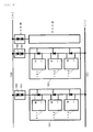
- FIG. 2 is a diagram exemplifying an abnormality detecting apparatus for a solar cell power generation system according to the present invention.
- FIG. 2 shows solar cell modules 111, 112, and 113, each having a solar cell panel mounted thereon.
- a bypass diode 104 is connected in parallel to each of the solar cell modules.
- the bypass diode 104 is provided for bypassing a generated current supplied from the solar cell module forward and backward in the case where a specified solar cell module cannot generate power due to lack of difference in potential between both terminals thereof by a failure or shade.
- a solar cell string 101 is configured by connecting the solar cell modules 111, 112, and 113 to each other in series.
- a power output generated in the solar cell string 101 is connected to backflow preventing diodes 141 and 142 through a connector 121, passes through the backflow preventing diodes 141 and 142, and then, is supplied to a power cable 150 connected to a power collecting terminal through a connector 122.
- the other output terminal of the solar cell string 101 is connected to a power cable 151 through a connector 123.
- the reason why the two backflow preventing diodes 141 and 142 are connected to each other in series is to enhance a reverse diode withstand voltage so as to satisfactorily withstand a reverse voltage applied to the backflow preventing diodes 141 and 142 when a difference in potential between the power cables 150 and 151 is large and a voltage generated in the solar cell module is reduced due to a failure etc.
- the number of solar cell modules connected to each other in series inside of the solar cell string 101 may be increased up to about 10 in order to increase the generated voltage up to the withstand voltage of the backflow preventing diode.
- the number of solar cell strings 101 in a solar cell power generation system depends upon a power generation scale. In general, the number may be widely varied from several tens to several ten thousands.
- An abnormality detecting apparatus 100 is characterized in that it includes measuring means for measuring a current flowing in the backflow preventing diode, and that an operation power of a constituent element in the abnormality detecting apparatus such as the measuring means is taken out from both terminals of the backflow preventing diode.
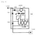
- a voltage taken out from an anode side of the backflow preventing diode 141 is converted into a required voltage in a voltage boosting DC converter 131 through a reverse withstand voltage protecting diode 143, and is supplied to each of circuits installed inside of the abnormality detecting apparatus.
- the abnormality detecting apparatus In the case where the abnormality detecting apparatus is required to be operated even when a solar cell can generate no power or only a small amount of power during nighttime or in the shade, the electric power from both terminals of the backflow preventing diode supplied upon power generation can be accumulated in a capacitor or the like.
- the reverse withstand voltage protecting diode 143 allows the voltage boosting DC converter 131 and an electric circuit such as the measuring means to be protected from a large negative breakdown voltage beyond a rating.
- the two backflow preventing diodes are connected to each other in series.
- a rating current at a forward current IF becomes extremely small in comparison with that of the backflow preventing diode. Therefore, a single diode having the performance capable of meeting a required reverse withstand rating voltage value may be selectively adopted.
- An input voltage to the voltage boosting DC converter 131 is equal to a voltage lower by a forward drop voltage V F , in which the reverse withstand voltage protecting diode 143 is inserted, than a voltage that is twice a forward voltage V F between both terminals of the backflow preventing diodes 141 and 142 connected to each other in series, and therefore, results in a small voltage of about 0.7 V.
- a voltage required for the electric circuit such as the measuring means and wireless communication means can be achieved from about 3 V to about 5 V.
- the voltage boosting DC converter 131 meeting the demand for the above input and output voltages can be easily implemented by the recent advance of technique.
- a current value is the most important information in order to detect the abnormal status of the power generation in the solar cell power generation system.
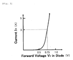
- a current generated in the solar cell string 101 passes through the backflow preventing diode. Therefore, the current value generated in the solar cell string 101 can be acquired by measuring the voltage between both terminals of the backflow preventing diode and calculating the current value based on a previously measured relationship between a forward voltage V F and a current I D in the backflow preventing diode.
- FIG. 3 is a graph illustrating a previously measured relationship between a forward voltage V F and a current I D in a backflow preventing diode.
- the current value becomes 3 A in accordance with the relationship illustrated in this graph.
- Such data measured as described above are transmitted to a central information control apparatus via a wireless communication circuit 146 and an antenna 147. It is determined based on these data whether or not the power generation status in the solar cell string is abnormal.
- the above-described abnormality detecting apparatus 100 is housed inside of a single casing 148 having a waterproof structure together with the backflow preventing diodes 141 and 142.
- the current value generated in the solar cell string can be obtained by the simple apparatus.
- the obtained current value includes a large error.
- description will be made on one example of an apparatus for acquiring information on an accurate current value even in the above-described case.
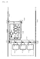
- FIG. 4 is a diagram exemplifying an abnormality detecting apparatus equipped with a function of measuring ambient temperature and a function of calculating a correct current value based on the ambient temperature and a measured voltage.
- a voltage boosting DC converter 131 allows the generation of a voltage suitable for actuating electric circuits such as the measuring means and the wireless communication means.
- Connectors 132 and 133 are connected to an output terminal of a solar cell string and a power cable 150.
- Backflow preventing diodes 141 and 142 prevent the current from flowing back to the solar cell panels in the case where the voltage generated in the solar cell string is lower than a potential generated in the power cable 150 due to some factor.
- this abnormality detecting apparatus includes a calculation control circuit 145, a wireless communication circuit 146, an antenna 147, and a waterproof casing 148.
- a temperature detecting diode 157 is supplied with a constant current via a resistance 156 connected to a thermally stable high output voltage in the voltage boosting DC converter 131. Moreover, voltage value obtained by measuring diode forward voltage VF between both terminals of the temperature detecting diode 157 by a multi-channel AD converter 158 is supplied to the calculation control circuit 145 as temperature information. On the other hand, diode forward voltage V F between both terminals of the backflow preventing diode is measured by the multi-channel AD converter 158, and then transmitted to the calculation control circuit 145.
- the calculation control circuit 145 stores therein the relationship between a forward voltage V F and a current I D in the backflow preventing diode 142 at each of previously measured temperatures. Based on this relationship, the current value generated in the solar cell string can be more accurately acquired by the calculation based on the temperature information and the voltage V F .
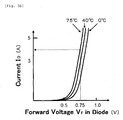
- FIG. 5(a) is a graph illustrating a relationship between a forward voltage VF and a temperature in a temperature detecting diode
- FIG. 5(b) is a graph illustrating a relationship between a forward voltage V F and a current I D , which are measured at each of the temperatures, in a backflow preventing diode.
- a constant current of 1 mA flows in the temperature detecting diode.
- the ambient temperature is 75°C based on the graph of FIG. 5(a) .
- a flowing current is calculated as being 4 A based on characteristics curve data at 75°C in FIG. 5(b) .
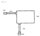
- FIG. 6 is a view showing an external appearance of the abnormality detecting apparatus for the solar cell power generation system according to the present invention.
- the waterproof casing 148 has a structure that can stand outdoor use. All of the constituent elements such as the backflow preventing diodes, the measuring means, and the wireless communication means described above are housed inside of the casing 148.
- the connectors 132 and 133 have a structure of an electric polarity so as to avoid any erroneous connection.
- Power cables 153 and 154 have a connection length of good operability enough to be connected to the power cables 150 and 151 connected to a power collecting terminal device.
- FIG. 7 is a diagram exemplifying maintenance using the abnormality detecting apparatus for the solar cell power generation system according to the present invention.
- the currents generated in the solar cell strings 101 pass through the abnormality detecting apparatus 100, which houses the backflow preventing diodes therein, are collected in a power collecting terminal apparatus 201 through the power cables 150 and 151, and thus, are processed to become a commercial power source as final outputs in a solar photovoltaic power generating apparatus.
- the antenna transmits the information on the status of the current generated in each of the solar cell strings etc.
- the central receiver 203 determines based on the predetermined data whether or not the information on the current etc. is abnormal, and further specifies an abnormal site while displaying a power generation situation by using a central information controlling apparatus 204, and if necessary, issues an instruction of inspection and maintenance.
- the wireless communication circuit in the abnormality detecting apparatus 100 may transmit the information such as the measurement data to the wireless communication circuit in another abnormality detecting apparatus existing within its communication range, so that the information can be finally transmitted to the central information controlling apparatus via each of the wireless communication means (i.e., multi-hop wireless communication). In this manner, it is possible to easily monitor the status of the solar cell strings with the simple configuration even when the installation area of the solar cell panel is large in scale so that the solar cell strings are located much apart from the central information controlling apparatus.
- the wireless communication means i.e., multi-hop wireless communication
- the wireless communication circuit 146 in one abnormality detecting apparatus capable of communicating with both of the central antenna 200 and another abnormality detecting apparatus located at a position where a radio wave cannot reach from the central antenna 200 is provided with the function capable of identifying the radio wave from the another abnormality detecting apparatus.
- the one abnormality detecting apparatus receives the radio wave, the one abnormality detecting apparatus retransmits the measured data together with its identified information to the central antenna 200.
- An abnormality detecting apparatus for the solar cell power generation system can accurately detect an abnormal status of power generation in a solar cell panel with a simple configuration. Moreover, the abnormality detecting apparatus can be easily installed inside of a branch casing incorporating backflow preventing diodes therein, and therefore, installation work is light, thereby reducing installation cost. Consequently, the abnormality detecting apparatus according to the present invention is remarkably useful for abnormality detection in a large-scaled mega solar system including numerous solar cell panels.
Landscapes
- Engineering & Computer Science (AREA)
- Computer Networks & Wireless Communication (AREA)
- Photovoltaic Devices (AREA)
Applications Claiming Priority (2)
| Application Number | Priority Date | Filing Date | Title |
|---|---|---|---|
| JP2009111698A JP4673921B2 (ja) | 2009-05-01 | 2009-05-01 | 太陽電池発電システムの異常検出装置及び方法 |
| PCT/JP2009/002264 WO2010125612A1 (ja) | 2009-05-01 | 2009-05-22 | 太陽電池発電システムの異常検出装置及び方法 |
Publications (3)
| Publication Number | Publication Date |
|---|---|
| EP2426725A1 EP2426725A1 (en) | 2012-03-07 |
| EP2426725A4 EP2426725A4 (en) | 2015-04-08 |
| EP2426725B1 true EP2426725B1 (en) | 2016-03-30 |
Family
ID=43031779
Family Applications (1)
| Application Number | Title | Priority Date | Filing Date |
|---|---|---|---|
| EP09843957.3A Not-in-force EP2426725B1 (en) | 2009-05-01 | 2009-05-22 | Apparatus for detecting abnormality of solar cell power generation system and method therefor |
Country Status (5)
| Country | Link |
|---|---|
| US (1) | US8581608B2 (enExample) |
| EP (1) | EP2426725B1 (enExample) |
| JP (1) | JP4673921B2 (enExample) |
| CN (1) | CN102318076B (enExample) |
| WO (1) | WO2010125612A1 (enExample) |
Families Citing this family (21)
| Publication number | Priority date | Publication date | Assignee | Title |
|---|---|---|---|---|
| US20100300509A1 (en) * | 2009-05-26 | 2010-12-02 | Douglas William Raymond | Solar photovoltaic modules with integral wireless telemetry |
| JP5295996B2 (ja) * | 2010-03-10 | 2013-09-18 | 株式会社東芝 | 太陽光発電システム |
| US9299861B2 (en) | 2010-06-15 | 2016-03-29 | Tenksolar, Inc. | Cell-to-grid redundandt photovoltaic system |
| JP5613963B2 (ja) * | 2011-01-17 | 2014-10-29 | 小真株式会社 | 太陽電池モジュール電源システム |
| JP2012156317A (ja) * | 2011-01-26 | 2012-08-16 | Icom Inc | 太陽電池発電装置 |
| US20120229161A1 (en) * | 2011-03-11 | 2012-09-13 | E-Lightric, Inc. | Method For Detecting Underperforming Solar Wafers In A Solar Panel or Underperforming Solar Panel in a Solar Array |
| KR101602800B1 (ko) * | 2011-10-31 | 2016-03-11 | 텐케이솔라 인코포레이티드 | 셀-격자 중복식 태양광발전 시스템 |
| DE102011089188A1 (de) * | 2011-12-20 | 2013-06-20 | Enextra Gmbh | Vorrichtung für Photovoltaik-Anlagen und Photovoltaik-Anlage |
| WO2013179655A1 (ja) * | 2012-05-29 | 2013-12-05 | 東京エレクトロン株式会社 | 太陽光発電監視方法及びその方法に用いられる太陽光発電監視システム |
| CN102841301A (zh) * | 2012-09-27 | 2012-12-26 | 常州旭能新能源科技有限公司 | 一种光伏组件监测系统 |
| JP2015079799A (ja) * | 2013-10-15 | 2015-04-23 | パナソニックIpマネジメント株式会社 | 発電監視装置及び発電監視システム |
| US20150162871A1 (en) * | 2013-12-06 | 2015-06-11 | Jean-Claude Koffi Rock | Method of Cell Isolation in Photovoltaic Solar Module or Solar Array |
| JP5567752B1 (ja) * | 2014-02-25 | 2014-08-06 | 株式会社ヒロセー | ストリング監視システム |
| ES2481091A1 (es) * | 2014-03-17 | 2014-07-29 | Universidad Politécnica de Madrid | Procedimiento para la detección automática de fallos en el funcionamiento de sistemas fotovoltaicos centralizados e instalación para la puesta en practica del mismo |
| CN105703710B (zh) * | 2014-11-28 | 2018-08-21 | 中电电气(上海)太阳能科技有限公司 | 一种带保护组件的el测试电路 |
| WO2016166787A1 (ja) * | 2015-04-13 | 2016-10-20 | 国立大学法人東京工業大学 | 太陽光発電システム |
| KR101858080B1 (ko) * | 2015-10-06 | 2018-06-29 | 한국에너지기술연구원 | 정션박스 조립체가 구비되는 태양전지 모듈 |
| JP6834334B2 (ja) * | 2016-10-17 | 2021-02-24 | 富士電機機器制御株式会社 | アーク故障検出システム |
| JP6834458B2 (ja) * | 2016-12-20 | 2021-02-24 | 富士電機機器制御株式会社 | アーク故障検出システム |
| CN107947324A (zh) * | 2017-12-11 | 2018-04-20 | 杭州博阳太阳能科技有限公司 | 一种太阳能供电系统 |
| TWI723851B (zh) * | 2020-04-21 | 2021-04-01 | 友達光電股份有限公司 | 太陽能電池檢測系統 |
Family Cites Families (12)
| Publication number | Priority date | Publication date | Assignee | Title |
|---|---|---|---|---|
| JPH0534199Y2 (enExample) * | 1987-06-20 | 1993-08-30 | ||
| US5669987A (en) * | 1994-04-13 | 1997-09-23 | Canon Kabushiki Kaisha | Abnormality detection method, abnormality detection apparatus, and solar cell power generating system using the same |
| JP3165606B2 (ja) * | 1994-12-27 | 2001-05-14 | シャープ株式会社 | 太陽電池モジュールの異常チェック機能付連系形太陽光発電装置 |
| JPH10201105A (ja) * | 1997-01-14 | 1998-07-31 | Nissin Electric Co Ltd | 太陽光発電装置 |
| JPH10326902A (ja) * | 1997-05-26 | 1998-12-08 | Canon Inc | 太陽電池出力特性の測定装置及びその測定方法 |
| JP2000196127A (ja) * | 1998-12-25 | 2000-07-14 | Honda Motor Co Ltd | 集光追尾式発電システムの故障診断装置及び故障診断方法 |
| JP2000269531A (ja) * | 1999-01-14 | 2000-09-29 | Canon Inc | 太陽電池モジュール、太陽電池モジュール付き建材、太陽電池モジュール外囲体及び太陽光発電装置 |
| JP2001068706A (ja) * | 1999-08-25 | 2001-03-16 | Sanyo Electric Co Ltd | 太陽電池装置 |
| JP2004260015A (ja) | 2003-02-26 | 2004-09-16 | Kyocera Corp | 太陽光発電装置 |
| JP2005044824A (ja) * | 2003-07-22 | 2005-02-17 | Fuji Electric Holdings Co Ltd | 太陽電池モジュールの故障検出方法および故障検出回路 |
| JP4515817B2 (ja) * | 2004-05-18 | 2010-08-04 | 株式会社三社電機製作所 | 太陽電池モジュール接続具 |
| US8204709B2 (en) * | 2005-01-18 | 2012-06-19 | Solar Sentry Corporation | System and method for monitoring photovoltaic power generation systems |
-
2009
- 2009-05-01 JP JP2009111698A patent/JP4673921B2/ja active Active
- 2009-05-22 CN CN200980136942.XA patent/CN102318076B/zh not_active Expired - Fee Related
- 2009-05-22 EP EP09843957.3A patent/EP2426725B1/en not_active Not-in-force
- 2009-05-22 US US13/058,327 patent/US8581608B2/en not_active Expired - Fee Related
- 2009-05-22 WO PCT/JP2009/002264 patent/WO2010125612A1/ja not_active Ceased
Also Published As
| Publication number | Publication date |
|---|---|
| CN102318076B (zh) | 2014-01-15 |
| CN102318076A (zh) | 2012-01-11 |
| EP2426725A4 (en) | 2015-04-08 |
| WO2010125612A1 (ja) | 2010-11-04 |
| US20110133764A1 (en) | 2011-06-09 |
| JP2010263027A (ja) | 2010-11-18 |
| US8581608B2 (en) | 2013-11-12 |
| JP4673921B2 (ja) | 2011-04-20 |
| EP2426725A1 (en) | 2012-03-07 |
Similar Documents
| Publication | Publication Date | Title |
|---|---|---|
| EP2426725B1 (en) | Apparatus for detecting abnormality of solar cell power generation system and method therefor | |
| US8446043B1 (en) | Photovoltaic array systems, methods, and devices and improved diagnostics and monitoring | |
| JP6336528B2 (ja) | 方法およびシステム | |
| US5669987A (en) | Abnormality detection method, abnormality detection apparatus, and solar cell power generating system using the same | |
| CN102362360B (zh) | 用于太阳能发电系统的故障检测方法 | |
| US8744791B1 (en) | Automatic generation and analysis of solar cell IV curves | |
| EP0677749A2 (en) | Abnormality detection method, abnormality detection apparatus, and power generating system using the same | |
| US20040211456A1 (en) | Apparatus, system, and method of diagnosing individual photovoltaic cells | |
| KR100918964B1 (ko) | 분산감지에 의한 태양전지판 고장을 검출하는 태양광 발전시스템 | |
| JP2007311487A (ja) | 太陽電池の特性評価装置 | |
| US10992257B2 (en) | State of health mechanisms for energy generation systems | |
| EP2725372B1 (en) | System and method of determination of connectivity resistance of power generating component | |
| US20120229161A1 (en) | Method For Detecting Underperforming Solar Wafers In A Solar Panel or Underperforming Solar Panel in a Solar Array | |
| KR20150127978A (ko) | 태양 광 발전모듈의 원격 진단시스템 | |
| EP3872985B1 (en) | Early detection of potential induced degradation in photovoltaic systems | |
| JP2011187808A (ja) | 太陽光発電システム | |
| KR20150033469A (ko) | 무선전송 단자함체를 적용한 태양광 발전설비의 다채널 계측 시스템 | |
| KR20220039505A (ko) | 태양전지모듈 센싱장치 |
Legal Events
| Date | Code | Title | Description |
|---|---|---|---|
| PUAI | Public reference made under article 153(3) epc to a published international application that has entered the european phase |
Free format text: ORIGINAL CODE: 0009012 |
|
| 17P | Request for examination filed |
Effective date: 20110705 |
|
| AK | Designated contracting states |
Kind code of ref document: A1 Designated state(s): AT BE BG CH CY CZ DE DK EE ES FI FR GB GR HR HU IE IS IT LI LT LU LV MC MK MT NL NO PL PT RO SE SI SK TR |
|
| DAX | Request for extension of the european patent (deleted) | ||
| RA4 | Supplementary search report drawn up and despatched (corrected) |
Effective date: 20150309 |
|
| RIC1 | Information provided on ipc code assigned before grant |
Ipc: H01L 31/04 20140101AFI20150303BHEP |
|
| GRAP | Despatch of communication of intention to grant a patent |
Free format text: ORIGINAL CODE: EPIDOSNIGR1 |
|
| INTG | Intention to grant announced |
Effective date: 20151001 |
|
| GRAS | Grant fee paid |
Free format text: ORIGINAL CODE: EPIDOSNIGR3 |
|
| GRAA | (expected) grant |
Free format text: ORIGINAL CODE: 0009210 |
|
| AK | Designated contracting states |
Kind code of ref document: B1 Designated state(s): AT BE BG CH CY CZ DE DK EE ES FI FR GB GR HR HU IE IS IT LI LT LU LV MC MK MT NL NO PL PT RO SE SI SK TR |
|
| REG | Reference to a national code |
Ref country code: GB Ref legal event code: FG4D |
|
| REG | Reference to a national code |
Ref country code: CH Ref legal event code: EP |
|
| REG | Reference to a national code |
Ref country code: AT Ref legal event code: REF Ref document number: 786211 Country of ref document: AT Kind code of ref document: T Effective date: 20160415 |
|
| REG | Reference to a national code |
Ref country code: IE Ref legal event code: FG4D |
|
| REG | Reference to a national code |
Ref country code: DE Ref legal event code: R096 Ref document number: 602009037431 Country of ref document: DE |
|
| REG | Reference to a national code |
Ref country code: LT Ref legal event code: MG4D |
|
| PG25 | Lapsed in a contracting state [announced via postgrant information from national office to epo] |
Ref country code: HR Free format text: LAPSE BECAUSE OF FAILURE TO SUBMIT A TRANSLATION OF THE DESCRIPTION OR TO PAY THE FEE WITHIN THE PRESCRIBED TIME-LIMIT Effective date: 20160330 Ref country code: GR Free format text: LAPSE BECAUSE OF FAILURE TO SUBMIT A TRANSLATION OF THE DESCRIPTION OR TO PAY THE FEE WITHIN THE PRESCRIBED TIME-LIMIT Effective date: 20160701 Ref country code: FI Free format text: LAPSE BECAUSE OF FAILURE TO SUBMIT A TRANSLATION OF THE DESCRIPTION OR TO PAY THE FEE WITHIN THE PRESCRIBED TIME-LIMIT Effective date: 20160330 Ref country code: NO Free format text: LAPSE BECAUSE OF FAILURE TO SUBMIT A TRANSLATION OF THE DESCRIPTION OR TO PAY THE FEE WITHIN THE PRESCRIBED TIME-LIMIT Effective date: 20160630 |
|
| PGFP | Annual fee paid to national office [announced via postgrant information from national office to epo] |
Ref country code: DE Payment date: 20160530 Year of fee payment: 8 |
|
| REG | Reference to a national code |
Ref country code: NL Ref legal event code: MP Effective date: 20160330 |
|
| REG | Reference to a national code |
Ref country code: AT Ref legal event code: MK05 Ref document number: 786211 Country of ref document: AT Kind code of ref document: T Effective date: 20160330 |
|
| PG25 | Lapsed in a contracting state [announced via postgrant information from national office to epo] |
Ref country code: SE Free format text: LAPSE BECAUSE OF FAILURE TO SUBMIT A TRANSLATION OF THE DESCRIPTION OR TO PAY THE FEE WITHIN THE PRESCRIBED TIME-LIMIT Effective date: 20160330 Ref country code: LT Free format text: LAPSE BECAUSE OF FAILURE TO SUBMIT A TRANSLATION OF THE DESCRIPTION OR TO PAY THE FEE WITHIN THE PRESCRIBED TIME-LIMIT Effective date: 20160330 Ref country code: LV Free format text: LAPSE BECAUSE OF FAILURE TO SUBMIT A TRANSLATION OF THE DESCRIPTION OR TO PAY THE FEE WITHIN THE PRESCRIBED TIME-LIMIT Effective date: 20160330 Ref country code: BE Free format text: LAPSE BECAUSE OF NON-PAYMENT OF DUE FEES Effective date: 20160531 |
|
| PGFP | Annual fee paid to national office [announced via postgrant information from national office to epo] |
Ref country code: IT Payment date: 20160531 Year of fee payment: 8 |
|
| PG25 | Lapsed in a contracting state [announced via postgrant information from national office to epo] |
Ref country code: NL Free format text: LAPSE BECAUSE OF FAILURE TO SUBMIT A TRANSLATION OF THE DESCRIPTION OR TO PAY THE FEE WITHIN THE PRESCRIBED TIME-LIMIT Effective date: 20160330 |
|
| PG25 | Lapsed in a contracting state [announced via postgrant information from national office to epo] |
Ref country code: IS Free format text: LAPSE BECAUSE OF FAILURE TO SUBMIT A TRANSLATION OF THE DESCRIPTION OR TO PAY THE FEE WITHIN THE PRESCRIBED TIME-LIMIT Effective date: 20160730 Ref country code: EE Free format text: LAPSE BECAUSE OF FAILURE TO SUBMIT A TRANSLATION OF THE DESCRIPTION OR TO PAY THE FEE WITHIN THE PRESCRIBED TIME-LIMIT Effective date: 20160330 Ref country code: PL Free format text: LAPSE BECAUSE OF FAILURE TO SUBMIT A TRANSLATION OF THE DESCRIPTION OR TO PAY THE FEE WITHIN THE PRESCRIBED TIME-LIMIT Effective date: 20160330 |
|
| PG25 | Lapsed in a contracting state [announced via postgrant information from national office to epo] |
Ref country code: AT Free format text: LAPSE BECAUSE OF FAILURE TO SUBMIT A TRANSLATION OF THE DESCRIPTION OR TO PAY THE FEE WITHIN THE PRESCRIBED TIME-LIMIT Effective date: 20160330 Ref country code: CZ Free format text: LAPSE BECAUSE OF FAILURE TO SUBMIT A TRANSLATION OF THE DESCRIPTION OR TO PAY THE FEE WITHIN THE PRESCRIBED TIME-LIMIT Effective date: 20160330 Ref country code: RO Free format text: LAPSE BECAUSE OF FAILURE TO SUBMIT A TRANSLATION OF THE DESCRIPTION OR TO PAY THE FEE WITHIN THE PRESCRIBED TIME-LIMIT Effective date: 20160330 Ref country code: SK Free format text: LAPSE BECAUSE OF FAILURE TO SUBMIT A TRANSLATION OF THE DESCRIPTION OR TO PAY THE FEE WITHIN THE PRESCRIBED TIME-LIMIT Effective date: 20160330 Ref country code: ES Free format text: LAPSE BECAUSE OF FAILURE TO SUBMIT A TRANSLATION OF THE DESCRIPTION OR TO PAY THE FEE WITHIN THE PRESCRIBED TIME-LIMIT Effective date: 20160330 Ref country code: PT Free format text: LAPSE BECAUSE OF FAILURE TO SUBMIT A TRANSLATION OF THE DESCRIPTION OR TO PAY THE FEE WITHIN THE PRESCRIBED TIME-LIMIT Effective date: 20160801 |
|
| PG25 | Lapsed in a contracting state [announced via postgrant information from national office to epo] |
Ref country code: BE Free format text: LAPSE BECAUSE OF FAILURE TO SUBMIT A TRANSLATION OF THE DESCRIPTION OR TO PAY THE FEE WITHIN THE PRESCRIBED TIME-LIMIT Effective date: 20160330 Ref country code: LU Free format text: LAPSE BECAUSE OF FAILURE TO SUBMIT A TRANSLATION OF THE DESCRIPTION OR TO PAY THE FEE WITHIN THE PRESCRIBED TIME-LIMIT Effective date: 20160522 |
|
| REG | Reference to a national code |
Ref country code: CH Ref legal event code: PL |
|
| REG | Reference to a national code |
Ref country code: DE Ref legal event code: R097 Ref document number: 602009037431 Country of ref document: DE |
|
| PG25 | Lapsed in a contracting state [announced via postgrant information from national office to epo] |
Ref country code: LI Free format text: LAPSE BECAUSE OF NON-PAYMENT OF DUE FEES Effective date: 20160531 Ref country code: CH Free format text: LAPSE BECAUSE OF NON-PAYMENT OF DUE FEES Effective date: 20160531 Ref country code: DK Free format text: LAPSE BECAUSE OF FAILURE TO SUBMIT A TRANSLATION OF THE DESCRIPTION OR TO PAY THE FEE WITHIN THE PRESCRIBED TIME-LIMIT Effective date: 20160330 |
|
| PLBE | No opposition filed within time limit |
Free format text: ORIGINAL CODE: 0009261 |
|
| STAA | Information on the status of an ep patent application or granted ep patent |
Free format text: STATUS: NO OPPOSITION FILED WITHIN TIME LIMIT |
|
| REG | Reference to a national code |
Ref country code: IE Ref legal event code: MM4A |
|
| GBPC | Gb: european patent ceased through non-payment of renewal fee |
Effective date: 20160630 |
|
| REG | Reference to a national code |
Ref country code: FR Ref legal event code: ST Effective date: 20170131 |
|
| 26N | No opposition filed |
Effective date: 20170103 |
|
| PG25 | Lapsed in a contracting state [announced via postgrant information from national office to epo] |
Ref country code: FR Free format text: LAPSE BECAUSE OF NON-PAYMENT OF DUE FEES Effective date: 20160531 |
|
| PG25 | Lapsed in a contracting state [announced via postgrant information from national office to epo] |
Ref country code: SI Free format text: LAPSE BECAUSE OF FAILURE TO SUBMIT A TRANSLATION OF THE DESCRIPTION OR TO PAY THE FEE WITHIN THE PRESCRIBED TIME-LIMIT Effective date: 20160330 Ref country code: GB Free format text: LAPSE BECAUSE OF NON-PAYMENT OF DUE FEES Effective date: 20160630 Ref country code: IE Free format text: LAPSE BECAUSE OF NON-PAYMENT OF DUE FEES Effective date: 20160522 |
|
| REG | Reference to a national code |
Ref country code: DE Ref legal event code: R119 Ref document number: 602009037431 Country of ref document: DE |
|
| PG25 | Lapsed in a contracting state [announced via postgrant information from national office to epo] |
Ref country code: DE Free format text: LAPSE BECAUSE OF NON-PAYMENT OF DUE FEES Effective date: 20171201 |
|
| PG25 | Lapsed in a contracting state [announced via postgrant information from national office to epo] |
Ref country code: HU Free format text: LAPSE BECAUSE OF FAILURE TO SUBMIT A TRANSLATION OF THE DESCRIPTION OR TO PAY THE FEE WITHIN THE PRESCRIBED TIME-LIMIT; INVALID AB INITIO Effective date: 20090522 Ref country code: IT Free format text: LAPSE BECAUSE OF NON-PAYMENT OF DUE FEES Effective date: 20170522 Ref country code: CY Free format text: LAPSE BECAUSE OF FAILURE TO SUBMIT A TRANSLATION OF THE DESCRIPTION OR TO PAY THE FEE WITHIN THE PRESCRIBED TIME-LIMIT Effective date: 20160330 |
|
| PG25 | Lapsed in a contracting state [announced via postgrant information from national office to epo] |
Ref country code: MK Free format text: LAPSE BECAUSE OF FAILURE TO SUBMIT A TRANSLATION OF THE DESCRIPTION OR TO PAY THE FEE WITHIN THE PRESCRIBED TIME-LIMIT Effective date: 20160330 Ref country code: TR Free format text: LAPSE BECAUSE OF FAILURE TO SUBMIT A TRANSLATION OF THE DESCRIPTION OR TO PAY THE FEE WITHIN THE PRESCRIBED TIME-LIMIT Effective date: 20160330 Ref country code: MC Free format text: LAPSE BECAUSE OF FAILURE TO SUBMIT A TRANSLATION OF THE DESCRIPTION OR TO PAY THE FEE WITHIN THE PRESCRIBED TIME-LIMIT Effective date: 20160330 Ref country code: MT Free format text: LAPSE BECAUSE OF NON-PAYMENT OF DUE FEES Effective date: 20160531 |
|
| PG25 | Lapsed in a contracting state [announced via postgrant information from national office to epo] |
Ref country code: BG Free format text: LAPSE BECAUSE OF FAILURE TO SUBMIT A TRANSLATION OF THE DESCRIPTION OR TO PAY THE FEE WITHIN THE PRESCRIBED TIME-LIMIT Effective date: 20160330 |