EP2426501A2 - Inspecting jig for testing circuits - Google Patents
Inspecting jig for testing circuits Download PDFInfo
- Publication number
- EP2426501A2 EP2426501A2 EP11007286A EP11007286A EP2426501A2 EP 2426501 A2 EP2426501 A2 EP 2426501A2 EP 11007286 A EP11007286 A EP 11007286A EP 11007286 A EP11007286 A EP 11007286A EP 2426501 A2 EP2426501 A2 EP 2426501A2
- Authority
- EP
- European Patent Office
- Prior art keywords
- guide
- connector
- relative position
- board
- probe
- Prior art date
- Legal status (The legal status is an assumption and is not a legal conclusion. Google has not performed a legal analysis and makes no representation as to the accuracy of the status listed.)
- Withdrawn
Links
- 239000000523 sample Substances 0.000 claims abstract description 146
- 230000008878 coupling Effects 0.000 claims abstract description 19
- 238000010168 coupling process Methods 0.000 claims abstract description 19
- 238000005859 coupling reaction Methods 0.000 claims abstract description 19
- 230000002093 peripheral effect Effects 0.000 claims description 2
- 238000007689 inspection Methods 0.000 description 14
- 230000003247 decreasing effect Effects 0.000 description 4
- 238000000034 method Methods 0.000 description 4
- 230000000007 visual effect Effects 0.000 description 4
- 239000000470 constituent Substances 0.000 description 3
- 210000000887 face Anatomy 0.000 description 3
- 230000002349 favourable effect Effects 0.000 description 3
- 230000008569 process Effects 0.000 description 3
- 229910052782 aluminium Inorganic materials 0.000 description 2
- XAGFODPZIPBFFR-UHFFFAOYSA-N aluminium Chemical compound [Al] XAGFODPZIPBFFR-UHFFFAOYSA-N 0.000 description 2
- 229910052751 metal Inorganic materials 0.000 description 2
- 239000002184 metal Substances 0.000 description 2
- 230000004048 modification Effects 0.000 description 2
- 238000012986 modification Methods 0.000 description 2
- 239000011347 resin Substances 0.000 description 2
- 229920005989 resin Polymers 0.000 description 2
- 230000015556 catabolic process Effects 0.000 description 1
- 230000007704 transition Effects 0.000 description 1
Images


Classifications
-
- G—PHYSICS
- G01—MEASURING; TESTING
- G01R—MEASURING ELECTRIC VARIABLES; MEASURING MAGNETIC VARIABLES
- G01R31/00—Arrangements for testing electric properties; Arrangements for locating electric faults; Arrangements for electrical testing characterised by what is being tested not provided for elsewhere
- G01R31/28—Testing of electronic circuits, e.g. by signal tracer
- G01R31/2801—Testing of printed circuits, backplanes, motherboards, hybrid circuits or carriers for multichip packages [MCP]
- G01R31/2806—Apparatus therefor, e.g. test stations, drivers, analysers, conveyors
- G01R31/2808—Holding, conveying or contacting devices, e.g. test adapters, edge connectors, extender boards
-
- G—PHYSICS
- G01—MEASURING; TESTING
- G01R—MEASURING ELECTRIC VARIABLES; MEASURING MAGNETIC VARIABLES
- G01R1/00—Details of instruments or arrangements of the types included in groups G01R5/00 - G01R13/00 and G01R31/00
- G01R1/02—General constructional details
- G01R1/06—Measuring leads; Measuring probes
- G01R1/067—Measuring probes
-
- G—PHYSICS
- G01—MEASURING; TESTING
- G01R—MEASURING ELECTRIC VARIABLES; MEASURING MAGNETIC VARIABLES
- G01R31/00—Arrangements for testing electric properties; Arrangements for locating electric faults; Arrangements for electrical testing characterised by what is being tested not provided for elsewhere
- G01R31/50—Testing of electric apparatus, lines, cables or components for short-circuits, continuity, leakage current or incorrect line connections
- G01R31/66—Testing of connections, e.g. of plugs or non-disconnectable joints
- G01R31/68—Testing of releasable connections, e.g. of terminals mounted on a printed circuit board
-
- H—ELECTRICITY
- H01—ELECTRIC ELEMENTS
- H01R—ELECTRICALLY-CONDUCTIVE CONNECTIONS; STRUCTURAL ASSOCIATIONS OF A PLURALITY OF MUTUALLY-INSULATED ELECTRICAL CONNECTING ELEMENTS; COUPLING DEVICES; CURRENT COLLECTORS
- H01R43/00—Apparatus or processes specially adapted for manufacturing, assembling, maintaining, or repairing of line connectors or current collectors or for joining electric conductors
Definitions
- the present invention relates to an inspecting jig for connecting a connector on a board of a device such as a mobile phone, to an inspecting apparatus by way of a probe.
- a relay connector for electrically connecting a connector to an inspecting apparatus, in JP-A-2008-140770 .
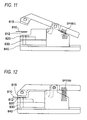
- This relay connector has such a structure, as shown in Figs. 11 and 12 (Related Art 1), that probes 830 are brought into contact with a connector 812, by clamping a board 810 and the connector 812 between a pressure block 815 and a guide 820.
- the connector 812 is electrically connected to the inspecting apparatus (not shown) by way of the probes 830 and a wiring pattern (not shown) of a wiring board 840, and thus, the inspection is carried out.
- Figs. 13 and 14 show an example where the probes 830 and the wiring board 840 are held at a side of the pressure block 815.
- Fig. 15 is a perspective view for exemplifying the connector 812 to be inspected.
- JP-A-2005-283218 discloses a connector inspecting jig for electrically connecting a connector to an inspecting apparatus.
- This connector inspecting jig is different from the relay connector disclosed in JP-A-2008-140770 , and so constructed that the probes are pressed against the connector from above of the board to be contacted with each other, without clamping the board and the connector.
- the relay connector disclosed in JP-A-2008-140770 is so constructed that the board and the connector are clamped. Therefore, there is a problem that although the relay connector favorably works, in case where the connector is in an end part of the board, it is difficult or impossible to bring the probes into contact with the connector, in case where the connector is in a center part of the board.
- the probes can be brought into contact with the connector, even in case where the connector is in the center part of the board, because it is so constructed that the probes are pressed against the connector from the above of the board, without clamping the board and connector.
- an inspecting jig operable to bring a probe into contact with a connector on a board
- the inspecting jig comprising: a probe holding body holding the probe; a guide guiding the probe to be brought into contact with the connector on the board, the guide being engaged with the connector thereby to be positioned with respect to the connector; and a coupling unit coupling the probe holding body and the guide so as to relatively move with respect to each other, between a first relative position and a second relative position, the first relative portion where a distal end of the probe is brought into contact with the connector when the guide is positioned with respect to the connector, the second relative position where the distal end of the probe is separated from the board and is separated from an imaginary line, which is perpendicular to the board and passes the connector, when the guide is positioned with respect to the connector.
- the connector can be visually observed, when the probe holding body and the guide are at least in the second relative position.
- the coupling unit may linearly couple the probe holding body and the guide so as to relatively move with respect to each other, between the first relative position and a third relative position where the distal end of the probe is separated from the board and the probe is in parallel with the imaginary line when the guide is positioned with respect to the connector.
- the guide may include a leg part which is erected toward the board, in such a manner that a side face of a lower end part of the leg part is butted against a side face of the connector, and a lower end of the leg part functions as a butting part to be butted against the board, in a state where the guide is positioned with respect to the connector.
- the guide may include a bottom face part, and first and second side wall parts which are erected from both sides of the bottom face parts to an opposite side to the board and which are opposed to each other, the first and second side wall parts may be erected from right and left sides of the bottom face part, whereas a front side may be open without a side wall part, and the connector can be visually observed from the front side through an opening in the bottom face part, when the probe holding body and the guide are in the second relative position.
- the inspecting jig may further include a spring provided between the probe holding body and the guide and urging the probe holding body and the guide to the second relative position.
- the coupling unit may include a guide groove or a guide slit provided in one of the probe holding body and the guide, and a boss or a rod member provided in the other of the probe holding body and the guide, and the boss or the rod member may be engaged with the guide groove or the guide slit to relatively move along the guide groove or the guide slit, thereby enabling the probe holding body and the guide to relatively move between the first relative position and the second relative position.
- the guide may include a bottom face part, a leg part which is erected from a peripheral edge of an opening in the bottom face part, and first and second side wall parts, which are erected from the bottom face part at both sides of a position where the leg part is erected, to an opposite side to the leg part, to be opposed to each other, the probe holding body may be positioned between the first and second side wall parts, and include first and second opposed faces to be opposed to the first and second side wall parts, the coupling unit may include a guide groove or a guide slit provided in one pair of the first and second opposed faces and the first and second side wall parts, and a boss or a rod member provided in the other pair of the first and second opposed faces and the first and second side wall parts, the boss or the rod member may be engaged with the guide groove or the guide slit to relatively move along the guide groove or the guide slit, thereby enabling the probe holding body and the guide to relatively move between the first relative position and the second relative position, and in a state where the guide is
- the leg part may have a tubular shape, and an inner side face of the leg part may be butted against the side face of the connector.
- the guide may be butted against the board only at the distal end of the leg part thereof.
- Fig. 1 is a side view of an inspecting jig in a first embodiment according to the invention.
- Fig. 1B is a partial enlarged view of a portion indicated by A shown in Fig. 1A .
- Fig. 2 is an exploded perspective view of the inspecting jig.
- This inspecting jig is used for conducting an inspection by bringing probes 17 into contact with a connector 2 to be inspected which is provided on a board 1, as shown in Fig. 1A (A number of electrodes are disposed on the connector 2 (See Fig. 15 ), with which the probes 17 are to be contacted).
- the inspecting jig includes a probe holding body 10, a guide 30, and a spring 90.
- the probe holding body 10 formed of insulating resin for example, has a sliding member 11, an on-board cover 15, an under-board cover 18, and a pin block 19.
- the sliding member 11 has a laterally symmetrical shape. As shown in Fig. 2 , the sliding member 11 has a first sliding part 111 which is opposed to (or contacted with) a first side wall part 35, which will be described below, thereby to slide relative to each other, and a second sliding part 112 which is opposed to (or contacted with) a second side wall part 37, which will be described below, thereby to slide relative to each other.
- the first and second sliding parts 111, 112 are integrally formed so that a space 113 is formed between them.
- the space 113 functions as a movable space of the spring 90, as described below.
- the first sliding part 111 is provided with guide grooves 11a, 11b having a mutually same shape, on a right side face thereof (the face opposed to the first side wall part 35) .
- the guide groove 11b is in such a positional relation with respect to the guide groove 11a that the guide groove 11a is displaced in parallel, on the right side face of the first sliding part 111.
- the second sliding part 112 is also provided with guide grooves having a mutually same shape (the same shape as the guide grooves 11a, 11b, although not shown in the drawings), on a left side face thereof (the face opposed to the second side wall part 37).
- These guide grooves constitute a coupling unit for coupling the probe holding body 10 and the guide 30, in combination with bosses 35a, 35b, 37a, 37b which will be described below.
- the first sliding part 111 has a through hole 115.
- the second sliding part 112 has a through hole (not shown in the drawings) in the same manner. Both ends of a rod member 119 formed of metal such as aluminum, for example, are respectively inserted into these through holes (both the ends do not protrude outside), so as to bridge the first and the second sliding parts 111, 112 through the space 113. One end of the spring 90 is attached to (hooked on) the rod member 119.
- the on-board cover 15 is fixed to a bottom face of the sliding member 11 with screws or the like.
- a wiring board 13 is fixed to the on-board cover 15 with screws or the like.
- An upper face of the wiring board 13 is covered with the on-board cover 15.
- a wiring pattern for connecting the probes 17 to an inspecting apparatus (not shown) is formed on the wiring board 13.
- An under-board cover 18 is fixed to the on-board cover 15 with screws or the like, at a position covering a part of a lower face of the wiring board 13, in other words, at a position clamping the wiring board 13 between the on-board cover 15 and the under-board cover 18 itself.
- the pin block 19 is fixed to the on-board cover 15 with screws or the like, at a position clamping the wiring board 13 between the on-board cover 15 and the pin block 19 itself.
- the pin block 19 may be integrally formed with the under-board cover 18, or may be separately formed.
- the probes 17 of a determined number are respectively inserted into through holes 161 in the pin block 19 to be held therein, and distal ends of the probes 17 are projected downward from the through holes 161 by a determined length.
- the probes 17 are preferably urged by springs (not shown) which are respectively incorporated therein, for example, in such a manner that the distal ends can be contracted so as to be withdrawn into the through holes 161, but the distal ends remain protruded from the through hole 161 by a determined length.
- the guide 30 which is formed of insulating resin, and preferably, colorless and transparent, has a bottom face part 31, and the first and second side wall parts 35, 37.
- the bottom face part 31 in a shape of a flat plate has an opening 32 in its center part.
- a leg part 33 is erected (projected downward) from an edge of the opening 32. Size of space inside of the opening 32 and the leg part 33 is equal to or a slightly larger than a size of a projected part 192 of the pin block 19 so that the projected part 192 of the pin block 19 can be guided without a backlash.
- a lower end of the leg part 33 is inwardly folded to form a folded part 331, and an opening 332 at a lower end of the leg part 33 has a size corresponding to the connector 2.
- the lower end opening 332 includes a taper part 333 having an opening which is gradually reduced from a distal end, by a determined length, and a butting part 334 having a constant opening extending upward from the taper part 333.
- the taper part 333 facilitates positioning of the leg part 33 (positioning of the guide 30) with respect to the connector 2.
- an inner side face of the butting part 334 is butted against side faces of the connector 2.
- the first and second side wall parts 35, 37 are erected from the bottom face part 31 to an opposite side to the leg part 33 (upward), at both sides of the position where the leg part 33 is erected, so as to be opposed to each other in parallel.
- Both ends of a rod member 38 formed of metal such as aluminum, for example, are respectively inserted into stepped through holes 352, 372 in the first and second side wall parts 35, 37, so as to bridge the first and second side wall parts 35, 37.
- the other end of the spring 90 is attached to (hooked on) the rod member 38.
- the bottom face part 31 and the leg part 33 are integrally formed, while the bottom face part 31 and the first and second side wall parts 35, 37 are separate bodies.
- the bottom face part 31, and the first and second side wall parts 35, 37 are fixed together with screws 313, 314, in a state where convex parts 351, 371 at respective center parts of lower ends of the first and second side wall parts 35, 37 are engaged with concave parts 311, 312 at both side edges of the bottom part 31.
- female thread holes are formed at both ends of the rod member 38, and screws 381, 382 are screwed into the female thread holes thereby to fix the rod member 38 to the first and second side wall parts 35, 37.
- the first and second side wall parts 35, 37 preferably have the same shape from a viewpoint of productivity.
- the bosses 35a, 35b which constitute the coupling unit in combination with the aforesaid guide grooves 11a, 11b are fitted into holes 353, 354 in the first side wall part 35.
- the bosses 37a, 37b which constitute the coupling unit are fitted into holes 373, 374 in the second side wall part 37.
- the bosses 35a, 35b are projected from the first side wall part 35, and the projected portions are engaged with the guide grooves 11a, 11b on the right side face of the sliding member 11 of the probe holding body 10 so as to relatively slide along the guide grooves 11a, 11b.
- the bosses 37a, 37b are engaged with the guide grooves (not shown) on the left side face of the sliding member 11 so as to relatively slide along the relevant guide grooves. Accordingly, the probe holding body 10 and the guide 30 can relatively slide with respect to each other.
- a slidable range is determined (restricted) by a shape of the guide grooves.
- the guide grooves 11a, 11b have first guide groove parts 121a, 121b for linearly guiding the bosses 35a, 35b in parallel with and in a longitudinal direction of the probes 17, and second guide groove parts 122a, 122b which are extended at a determined angle from lower ends of the first guide groove parts 121a, 121b for guiding the bosses 35a, 35b diagonally downward.
- Connection points between the first guide groove parts 121a, 121b and the second guide groove parts 122a, 122b are R-shaped so as not to be angulated.
- the probe holding body 10 is pulled with respect to the guide 30, by the spring 90 which interconnects the rod members 38 and 119, and the guide 30 is urged to a relative position as shown in Fig. 1A (and in Fig. 3A ) (corresponding to the second relative position).
- an inspector presses down the probe holding body 10 against an urging force of the spring 90, thereby to move the probe holding body 10 and the guide 30 from the relative position as shown in Fig. 1 (and in Fig. 3 ) to a relative position as shown in Fig. 4 (corresponding to the third relative position) and a relative position as shown in Fig. 5 (corresponding to the first relative position).
- the inspector sets the inspecting jig, as shown in Fig. 3A .
- the leg part 33 of the guide 30 is engaged with the connector 2 on the board 1. More specifically, the lower end of the leg part 33 is butted against the board 1 so that the connector 2 may be inserted into the lower end opening 332 of the leg part 33.
- the inner face of the butting part 334 of the lower end opening 332 is butted against the side faces of the connector 2.
- the probe holding body 10 and the guide 30 are maintained in the second relative position.
- the distal ends of the probes 17 are separated from the board 1, the probes 17 are in parallel with an imaginary line 5, which is perpendicular to the board 1 and passes the connector 2, and the distal ends of the probes 17 are separated from the imaginary line 5.
- the probe holding body 10 and the wiring board 13 are also separated from the imaginary line 5.
- the guide 30 has nothing which is erected upward from the bottom face part 31, except the first and second side wall parts 35, 37. Therefore, eyes of the inspector (shown by an arrow mark X in Fig. 3 ) can visually recognize the connector 2 through the opening 32 of the bottom face part 31, while the positioning step is carried out, and hence, good positioning workability can be obtained.
- the inspector presses down the probe holding body 10 against the urging force of the spring 90, thereby to relatively move the probe holding body 10 and the guide 30 from the second relative position as shown in Fig. 3A to the third relative position as shown in Fig. 4 .
- the bosses 35a, 35b are relatively moved along the guide groove parts 122a, 122b (The bosses 37a, 37b are also relatively moved, at the same time and in the same manner).
- the distal ends of the probes 17 are separated from the board 1, and the probes 17 are in parallel with the imaginary line 5 and positioned directly above the connector 2.
- the connector 2 is positioned on an imaginary extending line of the probes 17.
- the distal ends of the probes 17 come near the board 1, as compared with the second relative position.
- a distance between the distal ends of the probes 17 and the board 1 is flatly decreased.
- the probes 17 linearly move diagonally downward in a process of the relative movement from the second relative position to the third relative position, and hence, the distance between the distal ends of the probes 17 and the board 1 is not increased, but decreased.
- the inspector further presses down the probe holding body 10 resisting the urging force of the spring 90 thereby to relatively move the probe holding body 10 and the guide 30 linearly from the third relative position as shown in Fig. 4 to the first relative position as shown in Fig. 5 .
- the bosses 35a, 35b are relatively moved linearly along the guide groove parts 121a, 121b (The bosses 37a, 37b are also relatively moved, at the same time and in the same manner).
- a direction of the relative movement, on this occasion, is in parallel with the imaginary line 5 and the probes 17.
- the projected part 192 of the pin block 19 is inserted into the leg part 33 of the guide 30 (guided by the leg part 33), the probes 17 are in parallel with the imaginary line 5, and the distal ends of the probes 17 are brought into contact with the connector 2. Then, an object to be inspected such as an electronic component having the connector 2 is inspected. Specifically, the probes 17 receive a signal from the connector 2, and transmit the signal to an inspecting apparatus, which is not shown, by way of the wiring board 13. Alternatively, the signal sent from the inspecting apparatus, which is not shown, is transmitted from the probes 17 to the connector 2, by way of the wiring board 13. It is to be noted that the relative movement from the second relative position as shown in Fig.
- Fig. 6 is a side view of an inspecting jig according a second embodiment of the invention.
- Fig. 7 is an exploded perspective view of the inspecting jig.
- the probes 17 are moved in parallel between the respective relative positions in the first embodiment, the probes 17 are rotated in addition to the parallel movement, in this embodiment.
- the second embodiment will be described below, mainly referring to different points from the first embodiment.
- a guide slit 110 which is formed on a right side face of a sliding member 11 (herein, having a laterally symmetrical shape) includes a first guide slit part 121 having a linear shape in parallel with the probes 17, and a second guide slit part 122 having a curved shape such as an arc-shape.
- a left side face of the sliding member 11 is also formed with a guide slit (not shown) having the same shape, and both the guide slits are bridged by a rod member 38.
- Both ends of the rod member 38 passing through both the guide slits are respectively inserted into stepped through holes 352, 372 of first and second side wall parts 35, 37, and screws 381, 382 are screwed into female thread holes in the both ends thereby to fix the rod member 38 to the first and second side wall parts 35, 37.
- a boss 35a is fitted into a hole 353 in the first side wall part 35.
- a boss 37a is fitted into a hole 373 in the second side wall part 37.
- a portion of the boss 35a projected from the first side wall part 35 is engaged with a guide groove 11a (having a linear shape in parallel with the probes 17) on the right side face of the sliding member 11 of the probe holding body 10, and the boss 35a can relatively slide along the guide groove 11a.
- the boss 37a is engaged with a guide groove (not shown, having the same shape as the guide groove 11a) on the left side face of the sliding member 11, and can relatively slide along the relevant guide groove.
- a spring 90 is attached to (hooked on) a hooking part 118 of the sliding member 11, and the other end is attached to (hooked on) the rod member 38.
- the spring 90 urges the probe holding body 10 and the guide 30 to a relative position as shown in Fig. 6 (and in Fig. 8 ) (corresponding to the second relative position).
- an inspector rotates and presses down the probe holding body 10 resisting an urging force of the spring 90, thereby to relatively move the probe holding body 10 and the guide 30 from the relative position as shown in Fig. 6 (and in Fig. 8 ) to a relative position as shown in Fig. 9 (corresponding to the third relative position) and a relative position as shown in Fig. 10 (corresponding to the first relative position).
- the inspector sets the inspecting jig, as shown in Fig. 8 .
- the leg part 33 of the guide 30 is engaged with the connector 2 on the board 1.
- the probe holding body 10 and the guide 30 are in the second relative position under the urging force of the spring 90.
- the distal ends of the probes 17 are separated from the board 1, the probes 17 are perpendicular to an imaginary line 5, which is perpendicular to the board 1 and passes the connector 2, and the distal ends of the probes 17 are separated from the imaginary line 5.
- the probe holding body 10 and the wiring board 13 are also separated from the imaginary line 5.
- the guide 30 has nothing which is erected upward from the bottom face part 31, except the first and second side wall parts 35, 37.
- the inspector rotates the probe holding body 10 around the bosses 35a, 37a with respect to the guide 30, resisting the urging force of the spring 90, thereby to relatively move the probe holding body 10 and the guide 30 from the second relative position as shown in Fig. 8 to the third relative position as shown in Fig. 9 .
- the rod member 38 is relatively moved along the second guide slit part 122.
- the distal ends of the probes 17 are separated from the board 1, and the probes 17 are directly above the connector 2 in parallel with the imaginary line 5, and the connector 2 is positioned on an imaginary extending line of the probes 17.
- the distal ends of the probes 17 come near the board 1, as compared with the second relative position.
- the rod member 38 relatively moves linearly along the first guide slit part 121.
- the boss 35a relatively moves linearly along the guide groove 11a (The boss 37a too relatively moves at the same time and in the same manner).
- a direction of the relative movement on this occasion is in parallel with the imaginary line 5 and the probes 17.
- the projected part 192 of the pin block 19 is inserted into the leg part 33 of the guide 30 (guided by the leg part 33), the probes 17 are in parallel with the imaginary line 5, and the distal ends of the probes 17 are brought into contact with the connector 2. Then, the inspection is carried out on the object to be inspected having the connector 2.
- the probe holding body 10 and the guide 30 are returned to the second relative position as shown in Fig. 6 by the urging force of the spring 90.
- the guide groove 11a and the like in the embodiments may be a guide slit.
- such devices as forming the guide slit as a stepped slit had better be adopted.
- a rod member interconnecting the right and left guide slits may be provided instead of the bosses.
- the guide groove 11a and the like may be provided on the guide 30 (the first and second side wall parts 35, 37), and the boss 35a may be provided on the probe holding body 10 (the sliding member 11). In this case too, substantially the same relative movements can be realized.
- the spring 90 is not provided in view of cost or other reasons, although the operability is deteriorated.
- the leg part 33 is not necessarily in a shape shown in Fig. 2 and Fig. 7 . It is also possible to erect separate leg parts (for example, four), which guide the side faces of the projected part 192 of the pin block 19 and come into contact with the side faces of the connector 2, from the bottom face part 31.
- the leg part 33 may be formed in a tubular shape, and an inner side face of the leg part 33 is butted against a side face of the connector 2.
- the coupling unit couples the probe holding body and the guide so as to relatively move between the first relative position and the second relative position, and therefore, by maintaining the second relative position, when the guide is positioned with respect to the connector, more favorable visual observation can be secured, as compared with the jig in JP-A-2005-283218 .
- the board is not clamped in the structure according to the invention, and therefore, it is possible to bring the probe into contact with the connector, even in case where the connector is in a center part of the board.
Landscapes
- Engineering & Computer Science (AREA)
- Physics & Mathematics (AREA)
- General Physics & Mathematics (AREA)
- Computer Hardware Design (AREA)
- Microelectronics & Electronic Packaging (AREA)
- General Engineering & Computer Science (AREA)
- Manufacturing & Machinery (AREA)
- Manufacturing Of Electrical Connectors (AREA)
- Measuring Leads Or Probes (AREA)
- Testing Of Short-Circuits, Discontinuities, Leakage, Or Incorrect Line Connections (AREA)
Abstract
Description
- The present invention relates to an inspecting jig for connecting a connector on a board of a device such as a mobile phone, to an inspecting apparatus by way of a probe.
- In a small electronic apparatus such as a mobile phone, a digital camera, it has been conducted that a plurality of boards are disposed in a stacked manner, for the purpose of mounting a number of electronic circuits in a small space, and the boards are electrically connected by coupling connectors which are respectively provided on the boards. In order to inspect the boards and the connectors disposed thereon, it is necessary to electrically connect an inspecting apparatus to the connectors.
- The applicant has already proposed a relay connector for electrically connecting a connector to an inspecting apparatus, in
JP-A-2008-140770 Figs. 11 and 12 (Related Art 1), thatprobes 830 are brought into contact with aconnector 812, by clamping aboard 810 and theconnector 812 between apressure block 815 and aguide 820. Theconnector 812 is electrically connected to the inspecting apparatus (not shown) by way of theprobes 830 and a wiring pattern (not shown) of awiring board 840, and thus, the inspection is carried out.Figs. 13 and 14 (Related Art 2) show an example where theprobes 830 and thewiring board 840 are held at a side of thepressure block 815.Fig. 15 is a perspective view for exemplifying theconnector 812 to be inspected. -
JP-A-2005-283218 JP-A-2008-140770 - The relay connector disclosed in
JP-A-2008-140770 JP-A-2005-283218 JP-A-2005-283218 - It is therefore an object of the invention to provide an inspecting jig in which a probe can be brought into contact with a connector, even in case where the connector is in a center part of a board, and favorable visual observation of an inspector can be attained, when the probe is positioned with respect to the connector.
- In order to achieve the object, according to the invention, there is provided an inspecting jig operable to bring a probe into contact with a connector on a board, the inspecting jig comprising: a probe holding body holding the probe; a guide guiding the probe to be brought into contact with the connector on the board, the guide being engaged with the connector thereby to be positioned with respect to the connector; and a coupling unit coupling the probe holding body and the guide so as to relatively move with respect to each other, between a first relative position and a second relative position, the first relative portion where a distal end of the probe is brought into contact with the connector when the guide is positioned with respect to the connector, the second relative position where the distal end of the probe is separated from the board and is separated from an imaginary line, which is perpendicular to the board and passes the connector, when the guide is positioned with respect to the connector.
- The connector can be visually observed, when the probe holding body and the guide are at least in the second relative position.
- The coupling unit may linearly couple the probe holding body and the guide so as to relatively move with respect to each other, between the first relative position and a third relative position where the distal end of the probe is separated from the board and the probe is in parallel with the imaginary line when the guide is positioned with respect to the connector.
- The guide may include a leg part which is erected toward the board, in such a manner that a side face of a lower end part of the leg part is butted against a side face of the connector, and a lower end of the leg part functions as a butting part to be butted against the board, in a state where the guide is positioned with respect to the connector.
- The guide may include a bottom face part, and first and second side wall parts which are erected from both sides of the bottom face parts to an opposite side to the board and which are opposed to each other, the first and second side wall parts may be erected from right and left sides of the bottom face part, whereas a front side may be open without a side wall part, and the connector can be visually observed from the front side through an opening in the bottom face part, when the probe holding body and the guide are in the second relative position.
- The inspecting jig may further include a spring provided between the probe holding body and the guide and urging the probe holding body and the guide to the second relative position.
- The coupling unit may include a guide groove or a guide slit provided in one of the probe holding body and the guide, and a boss or a rod member provided in the other of the probe holding body and the guide, and the boss or the rod member may be engaged with the guide groove or the guide slit to relatively move along the guide groove or the guide slit, thereby enabling the probe holding body and the guide to relatively move between the first relative position and the second relative position.
- The guide may include a bottom face part, a leg part which is erected from a peripheral edge of an opening in the bottom face part, and first and second side wall parts, which are erected from the bottom face part at both sides of a position where the leg part is erected, to an opposite side to the leg part, to be opposed to each other, the probe holding body may be positioned between the first and second side wall parts, and include first and second opposed faces to be opposed to the first and second side wall parts, the coupling unit may include a guide groove or a guide slit provided in one pair of the first and second opposed faces and the first and second side wall parts, and a boss or a rod member provided in the other pair of the first and second opposed faces and the first and second side wall parts, the boss or the rod member may be engaged with the guide groove or the guide slit to relatively move along the guide groove or the guide slit, thereby enabling the probe holding body and the guide to relatively move between the first relative position and the second relative position, and in a state where the guide is positioned with respect to the connector, a side face of a distal end part of the leg part may be butted against a side face of the connector, and a distal end of the leg part may be butted against the board.
- The leg part may have a tubular shape, and an inner side face of the leg part may be butted against the side face of the connector.
- The guide may be butted against the board only at the distal end of the leg part thereof.
- It is to be noted that desired combinations of the above described constituent elements, and descriptions of the invention which are exchanged between methods and systems also effectively function as features of the invention.
-
-
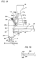
Fig. 1A is a side view of an inspecting jig in a first embodiment according to the invention.Fig. 1B is a partial enlarged view of a portion indicated by A shown inFig. 1A . -
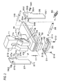
Fig. 2 is an exploded perspective view of the inspecting jig in the first embodiment. -
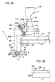
Fig. 3A is a side view of the inspecting jig in the first embodiment, when a guide is positioned with respect to a connector on a board.Fig. 3B is a partial enlarged view of a portion indicated by B shown inFig. 3B . -
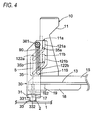
Fig. 4 is a side view of the inspecting jig in the first embodiment, when probes are directly above the connector. -
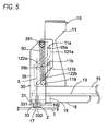
Fig. 5 is a side view of the inspecting jig in the first embodiment, when distal ends of the probes are brought into contact with the connector. -
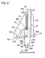
Fig. 6 is a side view of an inspecting jig in a second embodiment according to the invention. -
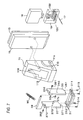
Fig. 7 is an exploded perspective view of the inspecting jig in the second embodiment. -
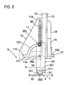
Fig. 8 is a side view of the inspecting jig in the second embodiment, when a guide is positioned with respect to a connector on a board. -
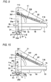
Fig. 9 is a side view of the inspecting jig in the second embodiment, when probes are directly above the connector. -
Fig. 10 is a side view of the inspecting jig in the second embodiment, when distal ends of the probes are brought into contact with the connector. -
Fig. 11 is a side view of a relay connector inRelated Art 1, when probes are not in contact with a connector. -
Fig. 12 is a side view of the relay connector inRelated Art 1, when the probes are in contact with the connector. -
Fig. 13 is a side view of a relay connector inRelated Art 2, when probes are not in contact with a connector. -
Fig. 14 is a side view of the relay connectorRelated Art 2, when the probes are in contact with the connector. -
Fig. 15 is a perspective view for exemplifying the connector to be inspected. - Now, preferred embodiments of the invention will be described in detail, referring to the drawings. It is to be noted that same reference numerals are given to the same or equivalent constituent elements, members and so on which are shown in the drawings, and overlapped descriptions are appropriately omitted. Moreover, the embodiments do not limit the invention, but only exemplify the invention, and all the features described in the embodiments and combinations of the features are not absolutely essential to the invention.
-
Fig. 1 is a side view of an inspecting jig in a first embodiment according to the invention.Fig. 1B is a partial enlarged view of a portion indicated by A shown inFig. 1A .Fig. 2 is an exploded perspective view of the inspecting jig. This inspecting jig is used for conducting an inspection by bringingprobes 17 into contact with aconnector 2 to be inspected which is provided on aboard 1, as shown inFig. 1A (A number of electrodes are disposed on the connector 2 (SeeFig. 15 ), with which theprobes 17 are to be contacted). The inspecting jig includes aprobe holding body 10, aguide 30, and aspring 90. - The
probe holding body 10 formed of insulating resin, for example, has a slidingmember 11, an on-board cover 15, an under-board cover 18, and apin block 19. The slidingmember 11 has a laterally symmetrical shape. As shown inFig. 2 , the slidingmember 11 has a first slidingpart 111 which is opposed to (or contacted with) a firstside wall part 35, which will be described below, thereby to slide relative to each other, and a second slidingpart 112 which is opposed to (or contacted with) a secondside wall part 37, which will be described below, thereby to slide relative to each other. The first and second slidingparts space 113 is formed between them. Thespace 113 functions as a movable space of thespring 90, as described below. - The first sliding
part 111 is provided withguide grooves guide groove 11b is in such a positional relation with respect to theguide groove 11a that theguide groove 11a is displaced in parallel, on the right side face of the first slidingpart 111. The second slidingpart 112 is also provided with guide grooves having a mutually same shape (the same shape as theguide grooves probe holding body 10 and theguide 30, in combination withbosses - The first sliding
part 111 has a throughhole 115. The second slidingpart 112 has a through hole (not shown in the drawings) in the same manner. Both ends of arod member 119 formed of metal such as aluminum, for example, are respectively inserted into these through holes (both the ends do not protrude outside), so as to bridge the first and the second slidingparts space 113. One end of thespring 90 is attached to (hooked on) therod member 119. - The on-
board cover 15 is fixed to a bottom face of the slidingmember 11 with screws or the like. Awiring board 13 is fixed to the on-board cover 15 with screws or the like. An upper face of thewiring board 13 is covered with the on-board cover 15. A wiring pattern for connecting theprobes 17 to an inspecting apparatus (not shown) is formed on thewiring board 13. An under-board cover 18 is fixed to the on-board cover 15 with screws or the like, at a position covering a part of a lower face of thewiring board 13, in other words, at a position clamping thewiring board 13 between the on-board cover 15 and the under-board cover 18 itself. - The
pin block 19 is fixed to the on-board cover 15 with screws or the like, at a position clamping thewiring board 13 between the on-board cover 15 and thepin block 19 itself. Thepin block 19 may be integrally formed with the under-board cover 18, or may be separately formed. Theprobes 17 of a determined number are respectively inserted into throughholes 161 in thepin block 19 to be held therein, and distal ends of theprobes 17 are projected downward from the throughholes 161 by a determined length. Theprobes 17 are preferably urged by springs (not shown) which are respectively incorporated therein, for example, in such a manner that the distal ends can be contracted so as to be withdrawn into the throughholes 161, but the distal ends remain protruded from the throughhole 161 by a determined length. - As shown in
Fig. 2 , theguide 30 which is formed of insulating resin, and preferably, colorless and transparent, has abottom face part 31, and the first and secondside wall parts bottom face part 31 in a shape of a flat plate has anopening 32 in its center part. Aleg part 33 is erected (projected downward) from an edge of theopening 32. Size of space inside of theopening 32 and theleg part 33 is equal to or a slightly larger than a size of a projectedpart 192 of thepin block 19 so that the projectedpart 192 of thepin block 19 can be guided without a backlash. As shown inFig. 1A , a lower end of theleg part 33 is inwardly folded to form a foldedpart 331, and anopening 332 at a lower end of theleg part 33 has a size corresponding to theconnector 2. As shown inFig. 1B , thelower end opening 332 includes ataper part 333 having an opening which is gradually reduced from a distal end, by a determined length, and abutting part 334 having a constant opening extending upward from thetaper part 333. Thetaper part 333 facilitates positioning of the leg part 33 (positioning of the guide 30) with respect to theconnector 2. On occasion of conducting the inspection, an inner side face of the buttingpart 334 is butted against side faces of theconnector 2. - The first and second
side wall parts bottom face part 31 to an opposite side to the leg part 33 (upward), at both sides of the position where theleg part 33 is erected, so as to be opposed to each other in parallel. Both ends of arod member 38 formed of metal such as aluminum, for example, are respectively inserted into stepped throughholes side wall parts side wall parts spring 90 is attached to (hooked on) therod member 38. - As shown in
Fig. 2 , thebottom face part 31 and theleg part 33 are integrally formed, while thebottom face part 31 and the first and secondside wall parts bottom face part 31, and the first and secondside wall parts screws convex parts side wall parts concave parts bottom part 31. Moreover, female thread holes are formed at both ends of therod member 38, and screws 381, 382 are screwed into the female thread holes thereby to fix therod member 38 to the first and secondside wall parts side wall parts - Coupling between the
probe holding body 10 and theguide 30 will be described. Thebosses aforesaid guide grooves holes side wall part 35. In the same manner, thebosses holes side wall part 37. Thebosses side wall part 35, and the projected portions are engaged with theguide grooves member 11 of theprobe holding body 10 so as to relatively slide along theguide grooves bosses member 11 so as to relatively slide along the relevant guide grooves. Accordingly, theprobe holding body 10 and theguide 30 can relatively slide with respect to each other. A slidable range is determined (restricted) by a shape of the guide grooves. - As shown in
Fig. 1A , theguide grooves guide groove parts bosses probes 17, and secondguide groove parts guide groove parts bosses guide groove parts guide groove parts - The
probe holding body 10 is pulled with respect to theguide 30, by thespring 90 which interconnects therod members guide 30 is urged to a relative position as shown inFig. 1A (and inFig. 3A ) (corresponding to the second relative position). On occasion of conducting the inspection, an inspector presses down theprobe holding body 10 against an urging force of thespring 90, thereby to move theprobe holding body 10 and theguide 30 from the relative position as shown inFig. 1 (and inFig. 3 ) to a relative position as shown inFig. 4 (corresponding to the third relative position) and a relative position as shown inFig. 5 (corresponding to the first relative position). - Now, a flow of the inspection using the inspecting jig in this embodiment will be described.
- The inspector sets the inspecting jig, as shown in
Fig. 3A . Specifically, theleg part 33 of theguide 30 is engaged with theconnector 2 on theboard 1. More specifically, the lower end of theleg part 33 is butted against theboard 1 so that theconnector 2 may be inserted into thelower end opening 332 of theleg part 33. As shown inFig. 3B , the inner face of the buttingpart 334 of thelower end opening 332 is butted against the side faces of theconnector 2. - On this occasion, urged by the
spring 90, theprobe holding body 10 and theguide 30 are maintained in the second relative position. In this second relative position, the distal ends of theprobes 17 are separated from theboard 1, theprobes 17 are in parallel with animaginary line 5, which is perpendicular to theboard 1 and passes theconnector 2, and the distal ends of theprobes 17 are separated from theimaginary line 5. Moreover, theprobe holding body 10 and thewiring board 13 are also separated from theimaginary line 5. Further, theguide 30 has nothing which is erected upward from thebottom face part 31, except the first and secondside wall parts Fig. 3 ) can visually recognize theconnector 2 through theopening 32 of thebottom face part 31, while the positioning step is carried out, and hence, good positioning workability can be obtained. - The inspector presses down the
probe holding body 10 against the urging force of thespring 90, thereby to relatively move theprobe holding body 10 and theguide 30 from the second relative position as shown inFig. 3A to the third relative position as shown inFig. 4 . Specifically, thebosses guide groove parts bosses probes 17 are separated from theboard 1, and theprobes 17 are in parallel with theimaginary line 5 and positioned directly above theconnector 2. Theconnector 2 is positioned on an imaginary extending line of theprobes 17. Moreover, the distal ends of theprobes 17 come near theboard 1, as compared with the second relative position. During the relative movement from the second relative position to the third relative position, a distance between the distal ends of theprobes 17 and theboard 1 is flatly decreased. Specifically, theprobes 17 linearly move diagonally downward in a process of the relative movement from the second relative position to the third relative position, and hence, the distance between the distal ends of theprobes 17 and theboard 1 is not increased, but decreased. - The inspector further presses down the
probe holding body 10 resisting the urging force of thespring 90 thereby to relatively move theprobe holding body 10 and theguide 30 linearly from the third relative position as shown inFig. 4 to the first relative position as shown inFig. 5 . Specifically, thebosses guide groove parts bosses imaginary line 5 and theprobes 17. - In this first relative position, the projected
part 192 of thepin block 19 is inserted into theleg part 33 of the guide 30 (guided by the leg part 33), theprobes 17 are in parallel with theimaginary line 5, and the distal ends of theprobes 17 are brought into contact with theconnector 2. Then, an object to be inspected such as an electronic component having theconnector 2 is inspected. Specifically, theprobes 17 receive a signal from theconnector 2, and transmit the signal to an inspecting apparatus, which is not shown, by way of thewiring board 13. Alternatively, the signal sent from the inspecting apparatus, which is not shown, is transmitted from theprobes 17 to theconnector 2, by way of thewiring board 13. It is to be noted that the relative movement from the second relative position as shown inFig. 3A to the first relative position as shown inFig. 5 is continuously performed without once stopping in the third relative position as shown inFig. 4 . When the inspecting jig is separated from theboard 1, after the inspection has been finished, theprobe holding body 10 and theguide 30 are returned to the second relative position as shown inFig. 1A , by the urging force of thespring 90. - According to this embodiment, the following advantages can be obtained.
- (1) Because the
probe holding body 10 and theguide 30 are coupled as described above, it is possible to maintain theprobes 17, theprobe holding body 10, and thewiring board 13 in a state separated from theimaginary line 5 which is perpendicular to theboard 1 and passes the connector 2 (in other words, directly above the connector 2), while the positioning step is carried out (the second relative position as shown inFigs. 1A and3A ) . Moreover, the side wall part is not present in front and in rear of theopening 32 of thebottom face part 31. Therefore, the inspector can visually observe theconnector 2 through the opening 32 from diagonally above at the front side. As the results, workability in the positioning step is enhanced, and there occur less errors, as compared with the structure in which the connector and its surroundings are covered with the guide plate, the probes, and the holding body, on occasion of positioning, as inJP-A-2005-283218 - (2) Because of the urging force of the
spring 90, the inspector can unconsciously maintain theprobe holding body 10 and theguide 30 in the second relative position as shown inFigs. 1A and3A , during the positioning step. Accordingly, favorable visual observation of theconnector 2 in the positioning step can be easily secured. Moreover, after the inspection has been finished, theprobe holding body 10 and theguide 30 are automatically returned by the urging force of thespring 90 from the first relative position as shown inFig. 5 to the second relative position as shown inFigs. 1A and3A , and therefore, smooth transition to the next inspection can be attained. - (3) The movement from the third relative position as shown in
Fig. 4 to the first relative position as shown inFig. 5 is linearly made in parallel with theimaginary line 5 and theprobes 17. Therefore, theprobes 17 can be perpendicularly butted against theconnector 2, and stress in the lateral direction (the direction perpendicular to the probes 17) is not generated. As the results, it is possible to prevent breakdown of theprobes 17, and butting reliability is enhanced. - (4) Because the
bottom face part 31 is colorless and transparent, theconnector 2 can be visually observed not only through theopening 32, but also through thebottom face part 31. As the results, the positioning workability is further enhanced. - (5) Because the
probes 17 are butted against theconnector 2 without interposing theboard 1, it is possible to conduct the inspection without any inconvenience, different from the structure inJP-A-2008-140770 connector 2 is in the center part of theboard 1. - (6) Because only the lower end of the
leg part 33 is the butting part to be butted against theboard 1, it is possible to conduct the inspection without any trouble, even though other components are present around theconnector 2 on theboard 1. - (7) Because the
guide grooves probes 17 and theboard 1 is flatly decreased in the process of the relative movement from the second relative position as shown inFig. 3A to the third relative position as shown inFig. 4 (In short, not increased but decreased). Specifically, in case of the relative movement from the second relative position as shown inFig. 3A to the first relative position as shown inFig. 5 , via the third relative position as shown inFig. 4 , the inspector need not apply a force in an upward direction to theprobe holding body 10. Therefore, the smooth relative movement from the second relative position as shown inFig. 3A to the first relative position as shown inFig. 5 can be easily made, without once stopping in the third relative position as shown inFig. 4 , and the workability is enhanced. -
Fig. 6 is a side view of an inspecting jig according a second embodiment of the invention.Fig. 7 is an exploded perspective view of the inspecting jig. Although theprobes 17 are moved in parallel between the respective relative positions in the first embodiment, theprobes 17 are rotated in addition to the parallel movement, in this embodiment. The second embodiment will be described below, mainly referring to different points from the first embodiment. - A guide slit 110 which is formed on a right side face of a sliding member 11 (herein, having a laterally symmetrical shape) includes a first guide slit
part 121 having a linear shape in parallel with theprobes 17, and a second guide slitpart 122 having a curved shape such as an arc-shape. A left side face of the slidingmember 11 is also formed with a guide slit (not shown) having the same shape, and both the guide slits are bridged by arod member 38. Both ends of therod member 38 passing through both the guide slits are respectively inserted into stepped throughholes side wall parts rod member 38 to the first and secondside wall parts - A
boss 35a is fitted into ahole 353 in the firstside wall part 35. Aboss 37a is fitted into ahole 373 in the secondside wall part 37. A portion of theboss 35a projected from the firstside wall part 35 is engaged with aguide groove 11a (having a linear shape in parallel with the probes 17) on the right side face of the slidingmember 11 of theprobe holding body 10, and theboss 35a can relatively slide along theguide groove 11a. Theboss 37a is engaged with a guide groove (not shown, having the same shape as theguide groove 11a) on the left side face of the slidingmember 11, and can relatively slide along the relevant guide groove. - One end of a
spring 90 is attached to (hooked on) a hookingpart 118 of the slidingmember 11, and the other end is attached to (hooked on) therod member 38. Thespring 90 urges theprobe holding body 10 and theguide 30 to a relative position as shown inFig. 6 (and inFig. 8 ) (corresponding to the second relative position). On occasion of conducting an inspection, an inspector rotates and presses down theprobe holding body 10 resisting an urging force of thespring 90, thereby to relatively move theprobe holding body 10 and theguide 30 from the relative position as shown inFig. 6 (and inFig. 8 ) to a relative position as shown inFig. 9 (corresponding to the third relative position) and a relative position as shown inFig. 10 (corresponding to the first relative position). - A flow of the inspection using the inspecting jig in this embodiment will be described below.
- The inspector sets the inspecting jig, as shown in
Fig. 8 . Specifically, theleg part 33 of theguide 30 is engaged with theconnector 2 on theboard 1. On this occasion, theprobe holding body 10 and theguide 30 are in the second relative position under the urging force of thespring 90. In this second relative position, the distal ends of theprobes 17 are separated from theboard 1, theprobes 17 are perpendicular to animaginary line 5, which is perpendicular to theboard 1 and passes theconnector 2, and the distal ends of theprobes 17 are separated from theimaginary line 5. Theprobe holding body 10 and thewiring board 13 are also separated from theimaginary line 5. Further, theguide 30 has nothing which is erected upward from thebottom face part 31, except the first and secondside wall parts Fig. 8 ) can visually observe theconnector 2 through theopening 32 in thebottom face part 31, and thus, good positioning workability can be attained. It is also possible to see theconnector 2 through thespace 113 in the slidingmember 11 and through theopening 32 in thebottom face part 31. - The inspector rotates the
probe holding body 10 around thebosses guide 30, resisting the urging force of thespring 90, thereby to relatively move theprobe holding body 10 and theguide 30 from the second relative position as shown inFig. 8 to the third relative position as shown inFig. 9 . Specifically, therod member 38 is relatively moved along the second guide slitpart 122. In this third relative position, the distal ends of theprobes 17 are separated from theboard 1, and theprobes 17 are directly above theconnector 2 in parallel with theimaginary line 5, and theconnector 2 is positioned on an imaginary extending line of theprobes 17. Moreover, the distal ends of theprobes 17 come near theboard 1, as compared with the second relative position. - The inspector presses down the
probe holding body 10 against the urging force of thespring 90 thereby to relatively move theprobe holding body 10 and theguide 30 linearly from the third relative position as shown inFig. 9 to a first relative position as shown inFig. 10 . Specifically, therod member 38 relatively moves linearly along the first guide slitpart 121. At the same time, theboss 35a relatively moves linearly along theguide groove 11a (Theboss 37a too relatively moves at the same time and in the same manner). A direction of the relative movement on this occasion is in parallel with theimaginary line 5 and theprobes 17. - In this first relative position, the projected
part 192 of thepin block 19 is inserted into theleg part 33 of the guide 30 (guided by the leg part 33), theprobes 17 are in parallel with theimaginary line 5, and the distal ends of theprobes 17 are brought into contact with theconnector 2. Then, the inspection is carried out on the object to be inspected having theconnector 2. When the inspecting jig is separated from theboard 1, after the inspection has been finished, theprobe holding body 10 and theguide 30 are returned to the second relative position as shown inFig. 6 by the urging force of thespring 90. - According to this second embodiment, operability is rather complicated, but in other points, substantially the same advantages as in the first embodiment can be achieved.
- Although the invention has been heretofore described referring to the embodiments by way of example, it is to be understood by those skilled in the art that various modifications can be added to the constituent elements and processes in the embodiments. Now, the modifications will be described.
- The
guide groove 11a and the like in the embodiments may be a guide slit. In this case, for preventing the bosses from being disengaged, such devices as forming the guide slit as a stepped slit had better be adopted. Alternatively, a rod member interconnecting the right and left guide slits may be provided instead of the bosses. - On the contrary to the embodiments, the
guide groove 11a and the like may be provided on the guide 30 (the first and secondside wall parts 35, 37), and theboss 35a may be provided on the probe holding body 10 (the sliding member 11). In this case too, substantially the same relative movements can be realized. - It is considered that the
spring 90 is not provided in view of cost or other reasons, although the operability is deteriorated. - The
leg part 33 is not necessarily in a shape shown inFig. 2 andFig. 7 . It is also possible to erect separate leg parts (for example, four), which guide the side faces of the projectedpart 192 of thepin block 19 and come into contact with the side faces of theconnector 2, from thebottom face part 31. Theleg part 33 may be formed in a tubular shape, and an inner side face of theleg part 33 is butted against a side face of theconnector 2. - According to an aspect of the invention, the coupling unit couples the probe holding body and the guide so as to relatively move between the first relative position and the second relative position, and therefore, by maintaining the second relative position, when the guide is positioned with respect to the connector, more favorable visual observation can be secured, as compared with the jig in
JP-A-2005-283218 JP-A-2008-140770
Claims (10)
- An inspecting jig operable to bring a probe into contact with a connector on a board, the inspecting jig comprising:a probe holding body holding the probe;a guide guiding the probe to be brought into contact with the connector on the board, the guide being engaged with the connector thereby to be positioned with respect to the connector; anda coupling unit coupling the probe holding body and the guide so as to relatively move with respect to each other, between a first relative position and a second relative position, the first relative portion where a distal end of the probe is brought into contact with the connector when the guide is positioned with respect to the connector, the second relative position where the distal end of the probe is separated from the board and is separated from an imaginary line, which is perpendicular to the board and passes the connector, when the guide is positioned with respect to the connector.
- The inspecting jig according to claim 1, wherein the connector can be visually observed, when the probe holding body and the guide are at least in the second relative position.
- The inspecting jig according to claim 1, wherein the coupling unit linearly couples the probe holding body and the guide so as to relatively move with respect to each other, between the first relative position and a third relative position where the distal end of the probe is separated from the board and the probe is in parallel with the imaginary line when the guide is positioned with respect to the connector.
- The inspecting jig according to claim 1, wherein the guide includes a leg part which is erected toward the board, in such a manner that a side face of a lower end part of the leg part is butted against a side face of the connector, and a lower end of the leg part functions as a butting part to be butted against the board, in a state where the guide is positioned with respect to the connector.
- The inspecting jig according to claim 1, wherein
the guide includes a bottom face part, and first and second side wall parts which are erected from both sides of the bottom face parts to an opposite side to the board and which are opposed to each other,
the first and second side wall parts are erected from right and left sides of the bottom face part, whereas a front side is open without a side wall part, and
the connector can be visually observed from the front side through an opening in the bottom face part, when the probe holding body and the guide are in the second relative position. - The inspecting jig according to claim 1 further comprising a spring provided between the probe holding body and the guide and urging the probe holding body and the guide to the second relative position.
- The inspecting jig according to claim 1, wherein
the coupling unit includes a guide groove or a guide slit provided in one of the probe holding body and the guide, and a boss or a rod member provided in the other of the probe holding body and the guide, and
the boss or the rod member is engaged with the guide groove or the guide slit to relatively move along the guide groove or the guide slit, thereby enabling the probe holding body and the guide to relatively move between the first relative position and the second relative position. - The inspecting jig according to claim 1, wherein
the guide includes a bottom face part, a leg part which is erected from a peripheral edge of an opening in the bottom face part, and first and second side wall parts, which are erected from the bottom face part at both sides of a position where the leg part is erected, to an opposite side to the leg part, to be opposed to each other,
the probe holding body is positioned between the first and second side wall parts, and includes first and second opposed faces to be opposed to the first and second side wall parts,
the coupling unit includes a guide groove or a guide slit provided in one pair of the first and second opposed faces and the first and second side wall parts, and a boss or a rod member provided in the other pair of the first and second opposed faces and the first and second side wall parts,
the boss or the rod member is engaged with the guide groove or the guide slit to relatively move along the guide groove or the guide slit, thereby enabling the probe holding body and the guide to relatively move between the first relative position and the second relative position, and
in a state where the guide is positioned with respect to the connector, a side face of a distal end part of the leg part is butted against a side face of the connector, and a distal end of the leg part is butted against the board. - The inspecting jig according to claim 8, wherein the leg part has a tubular shape, and an inner side face of the leg part is butted against the side face of the connector.
- The inspecting jig according to claim 8, the guide is butted against the board only at the distal end of the leg part thereof.
Applications Claiming Priority (1)
| Application Number | Priority Date | Filing Date | Title |
|---|---|---|---|
| JP2010199503A JP5579547B2 (en) | 2010-09-07 | 2010-09-07 | Inspection jig for connector connection |
Publications (2)
| Publication Number | Publication Date |
|---|---|
| EP2426501A2 true EP2426501A2 (en) | 2012-03-07 |
| EP2426501A3 EP2426501A3 (en) | 2017-11-22 |
Family
ID=44799472
Family Applications (1)
| Application Number | Title | Priority Date | Filing Date |
|---|---|---|---|
| EP11007286.5A Withdrawn EP2426501A3 (en) | 2010-09-07 | 2011-09-07 | Inspecting jig for testing circuits |
Country Status (6)
| Country | Link |
|---|---|
| US (1) | US9063195B2 (en) |
| EP (1) | EP2426501A3 (en) |
| JP (1) | JP5579547B2 (en) |
| KR (1) | KR101812809B1 (en) |
| CN (1) | CN102403642B (en) |
| TW (1) | TWI534443B (en) |
Families Citing this family (6)
| Publication number | Priority date | Publication date | Assignee | Title |
|---|---|---|---|---|
| US10506454B2 (en) | 2012-07-31 | 2019-12-10 | Dali Systems Co., Ltd. | Optimization of traffic load in a distributed antenna system |
| JP6114615B2 (en) * | 2013-04-05 | 2017-04-12 | モレックス エルエルシー | Connector fitting device and electronic device inspection method |
| CN105486970B (en) * | 2015-11-24 | 2019-02-15 | 深圳市思榕科技有限公司 | A kind of Pogopin module performance test macro and its test method |
| CN106546868A (en) * | 2016-10-13 | 2017-03-29 | 深圳市燕麦科技股份有限公司 | The lossless lower pin method of testing of B2B adapters and device |
| US10871507B2 (en) * | 2018-12-20 | 2020-12-22 | Texas Instruments Incorporated | Semiconductor device handler with chuck clamp interlock |
| KR102847400B1 (en) * | 2023-03-15 | 2025-08-18 | 한화솔루션 주식회사 | Probe connection device, its bracket assembly, and reverse bias processing apparatus including them |
Citations (2)
| Publication number | Priority date | Publication date | Assignee | Title |
|---|---|---|---|---|
| JP2005283218A (en) | 2004-03-29 | 2005-10-13 | Eight Kogyo:Kk | Connector inspection jig |
| JP2008140770A (en) | 2006-11-10 | 2008-06-19 | Yokowo Co Ltd | Relay connector |
Family Cites Families (22)
| Publication number | Priority date | Publication date | Assignee | Title |
|---|---|---|---|---|
| US4225819A (en) * | 1978-10-12 | 1980-09-30 | Bell Telephone Laboratories, Incorporated | Circuit board contact contamination probe |
| US4232262A (en) * | 1978-10-12 | 1980-11-04 | Emo George C | Connector contact terminal contamination probe |
| US4978912A (en) * | 1989-10-23 | 1990-12-18 | Ag Communication Systems Corporation | Chip carrier socket test probe |
| DE4116457C1 (en) * | 1991-05-21 | 1992-10-29 | Helmut 7800 Freiburg De Lang-Dahlke | |
| US5572144A (en) * | 1993-02-22 | 1996-11-05 | Seagate Technology | Test jig and method for probing a printed circuit board |
| JP2678875B2 (en) * | 1993-10-14 | 1997-11-19 | 日本航空電子工業株式会社 | Connector inspection jig |
| JP2940401B2 (en) * | 1994-06-10 | 1999-08-25 | 住友電装株式会社 | Connector inspection device |
| JP3293502B2 (en) * | 1996-12-20 | 2002-06-17 | セイコーエプソン株式会社 | Inspection device and inspection method for liquid crystal display device |
| JPH1152001A (en) * | 1997-07-31 | 1999-02-26 | Sumitomo Wiring Syst Ltd | Inspection part of connector-inspection apparatus |
| JPH11295376A (en) * | 1998-04-08 | 1999-10-29 | Yazaki Corp | Connector inspection tool |
| US6064195A (en) * | 1998-05-11 | 2000-05-16 | R-Tec Corporation | Test probe positioning device |
| JP2001194408A (en) * | 2000-01-11 | 2001-07-19 | Yazaki Corp | Contact structure between lance displacement detection pin of connector continuity inspection tool and lance of connector |
| EP1124136A1 (en) * | 2000-02-10 | 2001-08-16 | Sumitomo Wiring Systems, Ltd. | Electrical connection testing device and method for connector terminals |
| US6524123B2 (en) * | 2001-01-19 | 2003-02-25 | Agilent Technologies, Inc. | Self-aligning, quick-release connector |
| US6911814B2 (en) | 2003-07-01 | 2005-06-28 | Formfactor, Inc. | Apparatus and method for electromechanical testing and validation of probe cards |
| JP2006196211A (en) * | 2005-01-11 | 2006-07-27 | Nec Saitama Ltd | Base plate connector device and jig |
| JP4845031B2 (en) | 2006-11-10 | 2011-12-28 | 株式会社ヨコオ | Relay connector |
| US7656179B2 (en) | 2006-11-10 | 2010-02-02 | Yokowo Co., Ltd. | Relay connector having a pin block and a floating guide with guide hole |
| JP5004233B2 (en) * | 2007-11-08 | 2012-08-22 | 株式会社ヨコオ | Relay connector |
| JP2009162589A (en) * | 2007-12-28 | 2009-07-23 | Yazaki Corp | Connector continuity inspection jig |
| DE102008011240B4 (en) * | 2008-02-26 | 2016-11-17 | Airbus Ds Electronics And Border Security Gmbh | Device for contacting a T / R module with a test device |
| JP5203785B2 (en) * | 2008-04-16 | 2013-06-05 | 大西電子株式会社 | Inspection jig |
-
2010
- 2010-09-07 JP JP2010199503A patent/JP5579547B2/en not_active Expired - Fee Related
-
2011
- 2011-09-06 US US13/225,805 patent/US9063195B2/en not_active Expired - Fee Related
- 2011-09-07 EP EP11007286.5A patent/EP2426501A3/en not_active Withdrawn
- 2011-09-07 CN CN201110271359.9A patent/CN102403642B/en not_active Expired - Fee Related
- 2011-09-07 TW TW100132187A patent/TWI534443B/en not_active IP Right Cessation
- 2011-09-07 KR KR1020110090672A patent/KR101812809B1/en not_active Expired - Fee Related
Patent Citations (2)
| Publication number | Priority date | Publication date | Assignee | Title |
|---|---|---|---|---|
| JP2005283218A (en) | 2004-03-29 | 2005-10-13 | Eight Kogyo:Kk | Connector inspection jig |
| JP2008140770A (en) | 2006-11-10 | 2008-06-19 | Yokowo Co Ltd | Relay connector |
Also Published As
| Publication number | Publication date |
|---|---|
| JP5579547B2 (en) | 2014-08-27 |
| KR20120025439A (en) | 2012-03-15 |
| TW201234028A (en) | 2012-08-16 |
| EP2426501A3 (en) | 2017-11-22 |
| KR101812809B1 (en) | 2017-12-27 |
| US9063195B2 (en) | 2015-06-23 |
| CN102403642B (en) | 2015-06-24 |
| JP2012059427A (en) | 2012-03-22 |
| US20120119772A1 (en) | 2012-05-17 |
| TWI534443B (en) | 2016-05-21 |
| CN102403642A (en) | 2012-04-04 |
Similar Documents
| Publication | Publication Date | Title |
|---|---|---|
| US9063195B2 (en) | Inspecting jig | |
| US7656179B2 (en) | Relay connector having a pin block and a floating guide with guide hole | |
| KR102063019B1 (en) | Probe pin | |
| TWI438449B (en) | Relay connector | |
| EP3264535B1 (en) | Connector and camera device equipped therewith | |
| KR102564386B1 (en) | Connector apparatus having visible member | |
| US7568957B2 (en) | Relay connector | |
| KR20150146383A (en) | Electrical Contactor and Electrical Connecting Apparatus | |
| KR102599359B1 (en) | Probe replaceable pinboard and method for replacing probe on the pinboard | |
| EP3499652A2 (en) | Connector assembly and method of manufacturing socket for connector assembly | |
| KR101444787B1 (en) | Socket for testing electronics | |
| WO2019221076A1 (en) | Inspection jig and probe exchange system | |
| KR102333471B1 (en) | Terminal Position Inspection Device | |
| WO2018168136A1 (en) | Probe pin and inspection unit | |
| JP2012013649A (en) | Wire harness size inspection tool and wire harness size inspection method | |
| JP2018036129A (en) | Probe pin | |
| JP2001126815A (en) | connector | |
| JP6309788B2 (en) | connector | |
| JP2010015707A (en) | Connector | |
| US20200091644A1 (en) | Electric contact and socket for electric component | |
| JP2805551B2 (en) | Functional inspection equipment for mounted printed circuit boards | |
| JP3356081B2 (en) | Inspection equipment for electrical junction boxes | |
| US6239592B1 (en) | Test fixture with quick connect and release board interconnect mechanism | |
| JP4898600B2 (en) | A connector that enables efficient dimensional inspection. | |
| JP2002202338A (en) | Connector inspection unit and connector inspecting device using the same |
Legal Events
| Date | Code | Title | Description |
|---|---|---|---|
| AK | Designated contracting states |
Kind code of ref document: A2 Designated state(s): AL AT BE BG CH CY CZ DE DK EE ES FI FR GB GR HR HU IE IS IT LI LT LU LV MC MK MT NL NO PL PT RO RS SE SI SK SM TR |
|
| AX | Request for extension of the european patent |
Extension state: BA ME |
|
| PUAI | Public reference made under article 153(3) epc to a published international application that has entered the european phase |
Free format text: ORIGINAL CODE: 0009012 |
|
| PUAL | Search report despatched |
Free format text: ORIGINAL CODE: 0009013 |
|
| AK | Designated contracting states |
Kind code of ref document: A3 Designated state(s): AL AT BE BG CH CY CZ DE DK EE ES FI FR GB GR HR HU IE IS IT LI LT LU LV MC MK MT NL NO PL PT RO RS SE SI SK SM TR |
|
| AX | Request for extension of the european patent |
Extension state: BA ME |
|
| RIC1 | Information provided on ipc code assigned before grant |
Ipc: G01R 31/28 20060101ALI20171019BHEP Ipc: G01R 31/04 20060101AFI20171019BHEP |
|
| STAA | Information on the status of an ep patent application or granted ep patent |
Free format text: STATUS: THE APPLICATION IS DEEMED TO BE WITHDRAWN |
|
| 18D | Application deemed to be withdrawn |
Effective date: 20180523 |