EP2426344B1 - Heating system for an internal combustion engine - Google Patents
Heating system for an internal combustion engine Download PDFInfo
- Publication number
- EP2426344B1 EP2426344B1 EP10175608.8A EP10175608A EP2426344B1 EP 2426344 B1 EP2426344 B1 EP 2426344B1 EP 10175608 A EP10175608 A EP 10175608A EP 2426344 B1 EP2426344 B1 EP 2426344B1
- Authority
- EP
- European Patent Office
- Prior art keywords
- fuel
- lube oil
- internal combustion
- injector
- combustion engine
- Prior art date
- Legal status (The legal status is an assumption and is not a legal conclusion. Google has not performed a legal analysis and makes no representation as to the accuracy of the status listed.)
- Active
Links
Images

Classifications
-
- F—MECHANICAL ENGINEERING; LIGHTING; HEATING; WEAPONS; BLASTING
- F02—COMBUSTION ENGINES; HOT-GAS OR COMBUSTION-PRODUCT ENGINE PLANTS
- F02M—SUPPLYING COMBUSTION ENGINES IN GENERAL WITH COMBUSTIBLE MIXTURES OR CONSTITUENTS THEREOF
- F02M63/00—Other fuel-injection apparatus having pertinent characteristics not provided for in groups F02M39/00 - F02M57/00 or F02M67/00; Details, component parts, or accessories of fuel-injection apparatus, not provided for in, or of interest apart from, the apparatus of groups F02M39/00 - F02M61/00 or F02M67/00; Combination of fuel pump with other devices, e.g. lubricating oil pump
- F02M63/0001—Fuel-injection apparatus with specially arranged lubricating system, e.g. by fuel oil
-
- F—MECHANICAL ENGINEERING; LIGHTING; HEATING; WEAPONS; BLASTING
- F02—COMBUSTION ENGINES; HOT-GAS OR COMBUSTION-PRODUCT ENGINE PLANTS
- F02M—SUPPLYING COMBUSTION ENGINES IN GENERAL WITH COMBUSTIBLE MIXTURES OR CONSTITUENTS THEREOF
- F02M53/00—Fuel-injection apparatus characterised by having heating, cooling or thermally-insulating means
- F02M53/04—Injectors with heating, cooling, or thermally-insulating means
Definitions
- the present disclosure generally refers to internal combustion engines configured to burn fuel of a specific type, e.g. heavy fuel oil. More specifically, the present disclosure refers to internal combustion engines configured to operate in an operation mode in which said fuel is burned, and a standby mode in which no fuel is burned, wherein switching from the standby mode into the operation mode may be performed without burning any other fuel than said fuel, for example heavy fuel oil.
- fuel of a specific type e.g. heavy fuel oil.
- the present disclosure refers to internal combustion engines configured to operate in an operation mode in which said fuel is burned, and a standby mode in which no fuel is burned, wherein switching from the standby mode into the operation mode may be performed without burning any other fuel than said fuel, for example heavy fuel oil.
- the present disclosure refers to an internal combustion engine of the type mentioned herein comprising a heating system, and, in addition, to a method for operating an internal combustion engine of the type mentioned herein.
- Internal combustion engines e.g. common rail engines and, in particular, medium-speed common rail engines, may be configured to operate with a specific type of fuel having a relatively high viscosity.
- the types of fuel include, for example, diesel oil (DO), marine diesel oil (MDO), and particularly heavy fuel oil (HFO), as exemplary shown in Fig. 4 .
- DO diesel oil
- MDO marine diesel oil
- HFO heavy fuel oil
- the viscosity of these fuels may vary from 2.5 cSt to 16 cSt.
- internal combustion engine refers to internal combustion engines which may be used as main or auxiliary engines of ships/vessels such as cruiser liners, cargo ships, container ships, and tankers, or in power plants for production of heat and/or electricity.
- these engines which are also known as “middle” and “large” internal combustion engines, may be configured to bum at least one fuel selected from the group consisting of diesel, marine diesel oil (MDO), and heavy fuel oil (HFO).
- MDO marine diesel oil
- HFO heavy fuel oil
- Heavy fuel oil may contain "asphaltenes”. Asphaltenes may be defined as molecular substances that are found in crude oil, along with resins, aromatic hydrocarbon, and alcane (i.e, saturated hydrocarbons). Asphaltenes may consist primarily of carbon, hydrogen, nitrogen, oxygen, and sulfur, as well as great amounts of vanadium and nickel. Heavy oils may contain a much higher proportion of asphaltenes than of medium API graphic oil or light crude oils. Fuel Standard ISO 8217, for example, describes various parameters of "heavy fuel oil”, also referred to as “marine distillate fuels" or "marine residual fuels”.
- the fuel injectors used may become soiled by the fuel injected, particularly if a type of fuel with a high viscosity, particularly HFO, is injected.
- the problems may even get worse when the internal combustion engine is put in a standby mode as defined above.
- JP 2005146964 A discloses an arrangement including a pump, which supplies liquefied gas fuel from a feed pipe to an injection pipe connected to a fuel injection nozzle of a diesel engine.
- a cooling-medium path cools the injection pipe.
- US 7,383,794 shows an injection nozzle having channels connected to lubricant oil or motor oil lines, through which lubricant oil or motor oil can flow. These channels are arranged in the region of the nozzle needle. Channels connected to lubricant oil or motor oil lines, through which lubricant oil or motor oil can flow, are also arranged in the region of the control valve and/or an electromagnet actuating the control valve.
- the valve needle cooperating with the valve seat has a branch line which allows lubricating oil, such as motor oil, to flow.
- JP 2007303404A discloses a large sized two-cycle multi cylinder engine of cross head delivery type for use as a main engine in a power station.
- the engine has a valve that connects a medium-pressure pipe to an injection pipe via a control valve for fuel circulation.
- a control valve which connects an injection pipe to a common rail during start of fuel injection, controls the flow of heavy fuel oil from the common rail to an injection valve.
- a fuel valve has an intake connected to the control valve, and an output opening connected to a low pressure pipe.
- the injection pipe is connected to a medium-pressure pipe during fuel injection.
- a valve connects the pipe to the pipe via the control valve for fuel circulation, when the engine is not operating.
- KR 2008/068500 A shows a fuel filter unit for a fuel reduction system.
- the filter unit has a fuel injection port that is connected to a two-way valve via a link tube, said fuel injection port being provided to introduce fuel into a heating device.
- the valve selectively supplies fuel to be injected to the filters through the fuel injection port.
- the fuel injection port is connected to the valve through a link tube.
- CN 201351555 Y discloses an oil injector cooling unit for diesel engines, having an automatic temperature regulator connected to a feeding hole of a cooler, and a pressure oil pump coupled to a power driving device.
- the oil pump is driven by a power driving device.
- the cooling unit has a cooler, i.e. a tube bundle, that is connected to an oil feeding pipe to form two connecting points as a front parallel connection pivot (a) and a back parallel connection pivot (b).
- the automatic temperature regulator is provided in the front parallel connection pivot and connected to a feeding hole of the cooler.
- a pressure oil pump is provided in the back parallel connection pivot and connected to the oil feeding pipe.
- the pressure oil pump is connected to a power driving device, and is driven by the power driving device.
- US 3,945,353 A discloses a two phase fuel injection nozzle cooling system having a hydraulically cooled heat pipe.
- the heat pipe contains a hermetically sealed cooling medium which has a broiling point corresponding to the upper range of acceptable nozzle operating temperatures to transfer heat from the nozzle tip to the circulating hydraulic fluid which operates as a heat sink.
- US 4,432,329 A discloses an apparatus for easily starting up an engine under cold conditions and avoid any crystallization of the diesel oil under these conditions.
- the apparatus comprises a heat exchanger heating fuel by means of a heat-carrying fluid, such as the cooling liquid of the engine, when it has reached a predetermined minimum value.
- a reserve supply of hot fuel is connected to the heat exchanger.
- the reserve supply of hot fuel is connected to an injection pump.
- GB 1,121,013 A generally refers to fuel injection in internal combustion engines which operate on high-viscosity fuel.
- the document discloses an apparatus including an injection valve arranged to receive relatively high viscosity fuel from the supply source and to inject that fuel into in said engine.
- a pressure-tight closed circuit is operably selectively to supply heated or cooled fluid to said injection valve to control the temperature thereof and hence heat or cool the fuel injected thereby.
- the circuit incorporating a pump for circulating the fluid, a heating device, a cooling device, and a control valve operable to control the amount of fluid flowing through the heating and cooling device and hence the temperature of the fluid circulated through the injection valve.
- Means are provided operable to regulate the control valve in response to the temperatures recorded by the temperature sensitive elements located at the injection valve and in the fuel supply line. Water is circulated to heat and cool the injector.
- EP 0 304 742 A1 discloses a fuel injection system with controlled injectors for diesel engines. A system is provided for regulating the temperature of the fuel.
- US 3,354,872 A discloses a fuel supply system for an internal combustion engine comprising a water circulation heating the heavy fuel in a heat exchanger only during operation mode. Clean diesel is used for starting the internal combustion engine.
- WO 2006/021014 A 1 relates to an injection nozzle for injecting fuel into a combustion chamber of an internal combustion engine.
- the injection nozzle is provided with channels connected to lubricant oil and motor oil lines.
- the lubricant oil is used to cool the nozzle.
- the present disclosure is directed, at least in part, to improving or overcoming one or more aspects of prior systems.
- an internal combustion engine configured to be operated in an operation mode and a standby mode.
- a fuel of a specific type e.g. heavy fuel oil of the type mentioned herein
- the internal combustion engine does not burn any fuel. Switching from the standby mode into the operation mode may be performed without burning any other fuel than said fuel injected during the operation mode.
- the internal combustion engine comprises at least one injector configured to inject the specific fuel in an associated combustion chamber during the operation mode.
- the at least one fuel injector is configured such that lube oil for heating the at least one fuel injector can be circulated therein.
- a heating system of the internal combustion engine comprises a lube oil supply system and a fuel supply system.
- the lube oil supply system is configured to circulate lubricating oil, also known as "lube oil", through the at least one injector in order to heat the at least one injector.
- the fuel supply system is configured to circulate said fuel heated during the standby mode for maintaining a predetermined temperature of at least a part of the internal combustion engine.
- the fuel supply system is configured to supply said fuel to the at least one injector for injecting the same into the combustion chamber.
- a heat exchanger is provided. The heat exchanger is connected to the lube oil supply system and the fuel supply system.
- the heat exchanger is arranged upstream of the at least one injector and configured such that thermal energy from the fuel circulating in the fuel supply system is transferred to the lube oil circulating in the lube oil supply system.
- This thermal energy transfer is particularly be used for heating lube oil at a predetermined temperature, and, subsequently, for heating the at least one fuel injector during the standby mode by means of the heated lube oil.
- a method for operating an internal combustion engine comprises the step of circulating heated fuel during a standby mode of the internal combustion engine.
- no fuel may be burned in the combustion chamber.
- lube oil is circulated.
- a thermal energy transfer from the circulated heated fuel to the circulating lube oil, thereby heating the lube oil is performed upstream of the at least one injector during the standby mode of the internal combustion engine.
- the circulating heated lube oil is supplied through the at least one fuel injector which is configured to inject the fuel into an associated combustion chamber.
- Fig. 4 shows an exemplary diagram of an engine operation over a wide range of fuel viscosities.
- an internal combustion engine may include one or more injectors 15.
- Each injector 15 may be associated with a combustion chamber of the internal combustion engine.
- Each combustion chamber of the internal combustion engine may be equipped with one or more injectors 15.
- the injectors 15 may be configured to inject fuel into the associated combustion chamber.
- An injector 15 may have a structure as shown in Fig. 3 and will be discussed later in more detail.
- Each injector 15 may be connected to a branch line 55, which in turn may be connected to a common supply line 50 for heated lube oil.
- each injector 15 may be connected to a lube oil drain line 60.
- the common supply line 50 for heated lube oil may be connected to a primary lube oil supply line 70 and/or a secondary lube oil supply line 40.
- a check valve 45 or any other control means known in the art for controlling the supply of lube oil from the secondary lube oil supply line 40 into the common supply line 50 for lube oil may be provided.
- Another check valve 65 may be interconnected between the primary lube oil supply line 70 and the common supply line 50 for lube oil.
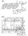
- a heat exchanger 25 may be provided in the arrangement shown in Fig. 1 , e.g. providing a heating system 10 for an internal combustion engine.
- the heat exchanger 25 may be coupled to a lube oil inlet 35 for cool lube oil and a fuel inlet 20 for heated fuel of a specific type, e.g. heavy fuel oil (HFO).
- the heat exchanger 25 may be also connected to a fuel outlet 30 and the secondary lube oil supply line 40.
- the heat exchanger 25 may be designed such that lube oil flowing via the lube oil inlet 35 into the heat exchanger 25 and the fuel flowing in the fuel inlet 20 into the heat exchanger, are guided within the heat exchanger 25 in a manner that at least part of the thermal energy of one of the fluids entering via the inlets 20 or 35 is exchanged between the fluids.
- That transfer of thermal energy may result in that fuel entering the heat exchanger 25 via the HFO inlet 20 leaves the heat exchanger 25 via outlet 30 with a temperature lower than the fuel's entering temperature, and lube oil entering the heat exchanger 25 via the lube oil inlet 35 leaves the heat exchanger 25 via the outlet or secondary lube oil supply line 40 with a temperature higher than the temperature of the lube oil at the entrance of the heat exchanger 25.
- the heat exchanger 25 may be of any type known in the art, in particular of the type including tube bundle heat exchangers, shell and tube heat exchangers, plate heat exchangers, plate fin heat exchangers etc.
- FIG. 2 Another schematic diagram of a part of an internal combustion engine equipped with a heating system 10 as outlined above, is shown in Fig. 2 .
- reference signs used in Fig. 2 that are identical with reference signs used in Fig. 1 may refer to the same components or elements. Accordingly, as far as elements or components in Fig. 2 are labeled with reference signs already mentioned with respect to Fig. 1 , it is referred to the corresponding explanations.
- the arrangement shown in Fig. 2 shows a an oil pan or reservoir 215 for lube oil 220.
- the reservoir 215 may include a pre-lubricating pump 240 for lube oil 220.
- the pre-lubricating pump 240 may be connected to the heat exchanger 25 via the lube oil inlet 35.
- a pipe coil 210 for lube oil may be housed in the heat exchanger 25.
- the pipe coil 210 for lube oil 220 may be connected to the lube oil inlet 35 at a first side and may be connected to the secondary lube oil supply line 40 at a second end of the pipe coil 210.
- the pipe coil 210 may be provided within a chamber 235 defined within the heat exchanger 25.
- the heat exchanger 25 itself may be arranged within a housing 24 of a fuel filter 23. However, the heat exchanger 25 may be also arranged at another location of the heating system 10. The arrangement within or as part of the fuel filter 23 may provide the benefit of reducing the size of the system.
- the lube oil drain lines 60 of each injector 15 may extend to the reservoir 215, whereby lube oil leaving an injector body 151 (see Fig. 3 ) of an injector 15 is guided back to the reservoir 215.
- the heat exchanger 25 as shown in Fig. 2 may be equipped with the fuel inlet 20 and the fuel outlet 30.
- the fuel outlet 30 may be connected to a common rail 300 from which fuel branch lines 310 are extending to each injector 15.
- a lube oil pump 250 e.g. mechanically driven by the internal combustion engine during the operation mode, may be provided and connected at an inlet side with the reservoir 215 via a line 255, and at an outlet side of the pump 250 with the primary lube oil supply line 70.
- a control unit 260 may be connected to the pump 240 and the the pump 270 for controlling the flow rate of the respective fluid, namely the lube oil and the fuel, flowing in the heat exchanger 25 via the lines 20 and 35 respectively.
- the pump 270 and the line 20, 30 may form a part of a fuel supply system 7.
- a lube oil supply system 6 may be formed by pumps 240 and/or 250 and associated lines, e.g. 35, 40, 50.
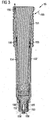
- Fig. 3 shows a longitudinal cross section of an exemplary embodiment of a fuel injector 15 as may be used in the systems shown in Fig. 1 or 2 and as described herein.
- the shown injector body 151 may be provided with lube oil channels 152, 153 and 154.
- the exemplary design of the channels 152, 153, 154 may be such that at least part of the injector 15 can be cooled or heated via the lube oil 220 flowing in direction 155.
- the channels 152 and 154 are straight, but in other exemplary embodiments these channels may be designed or shaped differently, e.g. like a coil, or the channels 152, 153, 154 may meander.
- the channel 153 is shown as a ring channel surrounding a movable injector needle 157, but can also have any other design appropriate for providing a thermal heat transfer from the lube oil flowing within channel 153 to parts of the injector 15 in the vicinity of channel 153. The same applies to channels 152, 154.
- two or more nozzle holes 158 are provided through which fuel can be injected into an associated combustion chamber (not shown).
- the point of time and the amount of fuel injected via the nozzle holes 158 may be controlled by the movable needle 157.
- An entrance opening of channel 152 at the upper side of the injector body 151 may be connected to an associated branch line 55.
- An outlet opening of channel 156 at the upper side of the injector body 151 may be connected to an associated drain line 60.
- Fig. 4 shows a diagram where kinematic viscosities and the viscosities of different types of fuel are plotted at different temperatures.
- the different kinematic viscosities and the different viscosities of various kinds of heavy fuel oil are plotted at different temperatures in comparison to marine gas oil and marine diesel oil.
- the limit for pre-heating and the limit of pumpability are also plotted for different temperatures.
- marine diesel oil need not be pre-heated to more than 50°C.
- the heavy fuel oil has to be pre-heated, because otherwise its viscosity would be too high and the HFO could not flow within the fuel supply lines and its components, particularly within the injectors. This problem may particularly arise in a standby mode when the internal combustion engine does not bum any fuel. Accordingly, it might be known that heavy fuel oil is pre-heated and circulated in the supply lines during the standby mode.
- the principle concept may include using lube oil heated by circulating fuel, e.g. heavy fuel oil, which itself is heated, to keep the injector warm, even in a standby mode.
- fuel e.g. heavy fuel oil
- fuel e.g. heavy fuel oil of the type mentioned, for example, in Fig. 4
- common rail 300 is supplied via common rail 300 and branch lines 310 to each injector 15.
- an appropriate amount of fuel may be injected into the associated combustion chamber at a controlled point of time.
- a common rail 300 is used to provide sufficient pressure to the fuel to be injected via the injectors 15.
- other technologies than common rail technology can also be used, for example an arrangement including separate high-pressure pumps connected to injectors.
- lube oil 220 may be supplied via the primary lube oil supply line 70 and the common supply line 50 and branch lines 55 to each injector 15.
- the lube oil 220 may flow in the direction as indicated by reference sign 155 in the injector body 151 within channels 152, 153 and 154, and leave the injector body 151 via the respective drain line 60.
- the lube oil 220 may cool each injector 15 and the lube oil 220 may have a temperature lower than the temperature of each injector 15 supplied with fuel at a high pressure, e.g. 1500 bar to 2000 bar or even more. Accordingly, the temperatures of the injectors 15 may rise during the operation mode and may have to be lowered by the lube oil 220 circulating therein.
- the fuel particularly heavy fuel oil
- a heating device may be provided for heating the circulating fuel during standby mode.
- check valve 65 may open due to the high pressure of the lube oil 220 supplied by the pump 250, and check valve 45 may close due to the lower pressure of the lube oil within line 40, so that no lube oil in the secondary lube oil supply line 40 can enter the common supply line 50.
- the pump 240 may be switched off during the operation mode.
- the system according to the present disclosure may operate as follows.
- the pump 240 may pump lube oil 220 from the reservoir 215 into the heat exchanger 25.
- heated fuel circulating in the fuel supply system 7 may be directed into heat exchanger 25 and may leave the heat exchanger via outlet 30.
- the heated fuel may be circulated back to the inlet 20 as indicated by the broken line in Fig. 2 .
- the temperature of the lube oil within the pipe coil 210 may be increased.
- the temperature increase may be controlled by a control unit, which may be connected to pump 240 and the fuel supply pump 270.
- the pumping rotation speed of the pump 240 and/or of the pump 270 may be adjusted, such that a desired temperature of the lube oil 220 leaving the heat exchanger 25 may be reached.
- Another alternative may include controlling mechanically the flow rate of heated lube oil 220 entering each injector 15.
- the flow rate of heated lube oil 220 entering the common supply line 50 may mechanically controlled, e.g. via an aperture plate.
- the aperture plate may be adjustable, such that the aperture diameter may be adjustable.
- the heated lube oil may leave the heat exchanger 25 via the secondary lube oil supply line 40 and may flow through the respective injector body 151 via the channels 152, 153, 154.
- the lube oil leaving each injector 15 may flow back to the reservoir 215 via drain lines 60. Accordingly, the temperatures of injectors 15 may be kept above a predetermined temperature level, such that a solidification of fuel or residues etc. in the proposed system, and particularly in the injectors 15, may be avoided or at least may be reduced.
Description
- The present disclosure generally refers to internal combustion engines configured to burn fuel of a specific type, e.g. heavy fuel oil. More specifically, the present disclosure refers to internal combustion engines configured to operate in an operation mode in which said fuel is burned, and a standby mode in which no fuel is burned, wherein switching from the standby mode into the operation mode may be performed without burning any other fuel than said fuel, for example heavy fuel oil.
- Furthermore, the present disclosure refers to an internal combustion engine of the type mentioned herein comprising a heating system, and, in addition, to a method for operating an internal combustion engine of the type mentioned herein.
- Internal combustion engines, e.g. common rail engines and, in particular, medium-speed common rail engines, may be configured to operate with a specific type of fuel having a relatively high viscosity. The types of fuel include, for example, diesel oil (DO), marine diesel oil (MDO), and particularly heavy fuel oil (HFO), as exemplary shown in
Fig. 4 . When supplied to the engine for combustion, the viscosity of these fuels may vary from 2.5 cSt to 16 cSt. - Generally, the term "internal combustion engine" refers to internal combustion engines which may be used as main or auxiliary engines of ships/vessels such as cruiser liners, cargo ships, container ships, and tankers, or in power plants for production of heat and/or electricity. In particular, these engines, which are also known as "middle" and "large" internal combustion engines, may be configured to bum at least one fuel selected from the group consisting of diesel, marine diesel oil (MDO), and heavy fuel oil (HFO).
- Heavy fuel oil may contain "asphaltenes". Asphaltenes may be defined as molecular substances that are found in crude oil, along with resins, aromatic hydrocarbon, and alcane (i.e, saturated hydrocarbons). Asphaltenes may consist primarily of carbon, hydrogen, nitrogen, oxygen, and sulfur, as well as great amounts of vanadium and nickel. Heavy oils may contain a much higher proportion of asphaltenes than of medium API graphic oil or light crude oils. Fuel Standard ISO 8217, for example, describes various parameters of "heavy fuel oil", also referred to as "marine distillate fuels" or "marine residual fuels".
- The fuel injectors used may become soiled by the fuel injected, particularly if a type of fuel with a high viscosity, particularly HFO, is injected. The problems may even get worse when the internal combustion engine is put in a standby mode as defined above.
-
JP 2005146964 A -
US 7,383,794 shows an injection nozzle having channels connected to lubricant oil or motor oil lines, through which lubricant oil or motor oil can flow. These channels are arranged in the region of the nozzle needle. Channels connected to lubricant oil or motor oil lines, through which lubricant oil or motor oil can flow, are also arranged in the region of the control valve and/or an electromagnet actuating the control valve. The valve needle cooperating with the valve seat has a branch line which allows lubricating oil, such as motor oil, to flow. -
JP 2007303404A -
KR 2008/068500 A -
CN 201351555 Y discloses an oil injector cooling unit for diesel engines, having an automatic temperature regulator connected to a feeding hole of a cooler, and a pressure oil pump coupled to a power driving device. The oil pump is driven by a power driving device. The cooling unit has a cooler, i.e. a tube bundle, that is connected to an oil feeding pipe to form two connecting points as a front parallel connection pivot (a) and a back parallel connection pivot (b). The automatic temperature regulator is provided in the front parallel connection pivot and connected to a feeding hole of the cooler. A pressure oil pump is provided in the back parallel connection pivot and connected to the oil feeding pipe. The pressure oil pump is connected to a power driving device, and is driven by the power driving device. -
US 3,945,353 A discloses a two phase fuel injection nozzle cooling system having a hydraulically cooled heat pipe. The heat pipe contains a hermetically sealed cooling medium which has a broiling point corresponding to the upper range of acceptable nozzle operating temperatures to transfer heat from the nozzle tip to the circulating hydraulic fluid which operates as a heat sink. -
US 4,432,329 A discloses an apparatus for easily starting up an engine under cold conditions and avoid any crystallization of the diesel oil under these conditions. The apparatus comprises a heat exchanger heating fuel by means of a heat-carrying fluid, such as the cooling liquid of the engine, when it has reached a predetermined minimum value. A reserve supply of hot fuel is connected to the heat exchanger. The reserve supply of hot fuel is connected to an injection pump. -
GB 1,121,013 A -
EP 0 304 742 A1 discloses a fuel injection system with controlled injectors for diesel engines. A system is provided for regulating the temperature of the fuel. -
US 3,354,872 A discloses a fuel supply system for an internal combustion engine comprising a water circulation heating the heavy fuel in a heat exchanger only during operation mode. Clean diesel is used for starting the internal combustion engine. -
WO 2006/021014 relates to an injection nozzle for injecting fuel into a combustion chamber of an internal combustion engine. The injection nozzle is provided with channels connected to lubricant oil and motor oil lines. The lubricant oil is used to cool the nozzle.A 1 - In internal combustion engines of the type mentioned herein, the possible negative effects of fuels particularly fuels having a relatively high viscosity, shall be addressed. The present disclosure is directed, at least in part, to improving or overcoming one or more aspects of prior systems.
- According to a first aspect of the present disclosure, an internal combustion engine is provided. The internal combustion engine is configured to be operated in an operation mode and a standby mode. During the operation mode, a fuel of a specific type, e.g. heavy fuel oil of the type mentioned herein, is injected into an associated combustion chamber via at least one injector. During the standby mode, the internal combustion engine does not burn any fuel. Switching from the standby mode into the operation mode may be performed without burning any other fuel than said fuel injected during the operation mode. The internal combustion engine comprises at least one injector configured to inject the specific fuel in an associated combustion chamber during the operation mode. The at least one fuel injector is configured such that lube oil for heating the at least one fuel injector can be circulated therein. A heating system of the internal combustion engine comprises a lube oil supply system and a fuel supply system. The lube oil supply system is configured to circulate lubricating oil, also known as "lube oil", through the at least one injector in order to heat the at least one injector. The fuel supply system is configured to circulate said fuel heated during the standby mode for maintaining a predetermined temperature of at least a part of the internal combustion engine. During the operation mode, the fuel supply system is configured to supply said fuel to the at least one injector for injecting the same into the combustion chamber. A heat exchanger is provided. The heat exchanger is connected to the lube oil supply system and the fuel supply system. The heat exchanger is arranged upstream of the at least one injector and configured such that thermal energy from the fuel circulating in the fuel supply system is transferred to the lube oil circulating in the lube oil supply system. This thermal energy transfer is particularly be used for heating lube oil at a predetermined temperature, and, subsequently, for heating the at least one fuel injector during the standby mode by means of the heated lube oil.
- According to another aspect of the present disclosure, a method for operating an internal combustion engine is provided. The method comprises the step of circulating heated fuel during a standby mode of the internal combustion engine. During the standby mode, no fuel may be burned in the combustion chamber. In addition, during the standby mode of the internal combustion chamber, lube oil is circulated. Furthermore, a thermal energy transfer from the circulated heated fuel to the circulating lube oil, thereby heating the lube oil, is performed upstream of the at least one injector during the standby mode of the internal combustion engine. During the standby mode of the internal combustion engine, the circulating heated lube oil is supplied through the at least one fuel injector which is configured to inject the fuel into an associated combustion chamber.
- Other features and aspects of this disclosure will be apparent from the following description and the accompanying drawings.
-
-
Fig. 1 shows a schematic diagram of an exemplary embodiment of a heating system for an internal combustion engine according to the present disclosure, -
Fig. 2 shows another schematic view of an exemplary embodiment of a part of an internal combustion engine and a heating system according to the present disclosure, -
Fig. 3 shows an exemplary embodiment of a fuel injector which may be used in an internal combustion engine according to the present disclosure, and -
Fig. 4 shows an exemplary diagram of an engine operation over a wide range of fuel viscosities. - Referring to
Fig. 1 , an internal combustion engine (only partly shown) may include one ormore injectors 15. Eachinjector 15 may be associated with a combustion chamber of the internal combustion engine. In other words: Each combustion chamber of the internal combustion engine may be equipped with one ormore injectors 15. Theinjectors 15 may be configured to inject fuel into the associated combustion chamber. Aninjector 15 may have a structure as shown inFig. 3 and will be discussed later in more detail. Eachinjector 15 may be connected to abranch line 55, which in turn may be connected to acommon supply line 50 for heated lube oil. Furthermore, eachinjector 15 may be connected to a lubeoil drain line 60. - The
common supply line 50 for heated lube oil may be connected to a primary lubeoil supply line 70 and/or a secondary lubeoil supply line 40. Acheck valve 45 or any other control means known in the art for controlling the supply of lube oil from the secondary lubeoil supply line 40 into thecommon supply line 50 for lube oil may be provided. Anothercheck valve 65 may be interconnected between the primary lubeoil supply line 70 and thecommon supply line 50 for lube oil. - A
heat exchanger 25 may be provided in the arrangement shown inFig. 1 , e.g. providing aheating system 10 for an internal combustion engine. Theheat exchanger 25 may be coupled to alube oil inlet 35 for cool lube oil and afuel inlet 20 for heated fuel of a specific type, e.g. heavy fuel oil (HFO). Theheat exchanger 25 may be also connected to afuel outlet 30 and the secondary lubeoil supply line 40. Theheat exchanger 25 may be designed such that lube oil flowing via thelube oil inlet 35 into theheat exchanger 25 and the fuel flowing in thefuel inlet 20 into the heat exchanger, are guided within theheat exchanger 25 in a manner that at least part of the thermal energy of one of the fluids entering via theinlets heat exchanger 25 via theHFO inlet 20 leaves theheat exchanger 25 viaoutlet 30 with a temperature lower than the fuel's entering temperature, and lube oil entering theheat exchanger 25 via thelube oil inlet 35 leaves theheat exchanger 25 via the outlet or secondary lubeoil supply line 40 with a temperature higher than the temperature of the lube oil at the entrance of theheat exchanger 25. - The
heat exchanger 25 may be of any type known in the art, in particular of the type including tube bundle heat exchangers, shell and tube heat exchangers, plate heat exchangers, plate fin heat exchangers etc. - Another schematic diagram of a part of an internal combustion engine equipped with a
heating system 10 as outlined above, is shown inFig. 2 . It shall be noted that reference signs used inFig. 2 that are identical with reference signs used inFig. 1 may refer to the same components or elements. Accordingly, as far as elements or components inFig. 2 are labeled with reference signs already mentioned with respect toFig. 1 , it is referred to the corresponding explanations. - The arrangement shown in
Fig. 2 shows a an oil pan orreservoir 215 forlube oil 220. Thereservoir 215 may include apre-lubricating pump 240 forlube oil 220. Thepre-lubricating pump 240 may be connected to theheat exchanger 25 via thelube oil inlet 35. In this exemplary embodiment of the present disclosure, apipe coil 210 for lube oil may be housed in theheat exchanger 25. Thepipe coil 210 forlube oil 220 may be connected to thelube oil inlet 35 at a first side and may be connected to the secondary lubeoil supply line 40 at a second end of thepipe coil 210. Thepipe coil 210 may be provided within achamber 235 defined within theheat exchanger 25. - The
heat exchanger 25 itself may be arranged within a housing 24 of afuel filter 23. However, theheat exchanger 25 may be also arranged at another location of theheating system 10. The arrangement within or as part of thefuel filter 23 may provide the benefit of reducing the size of the system. - As shown in
Fig. 2 , the lubeoil drain lines 60 of eachinjector 15 may extend to thereservoir 215, whereby lube oil leaving an injector body 151 (seeFig. 3 ) of aninjector 15 is guided back to thereservoir 215. - The
heat exchanger 25 as shown inFig. 2 may be equipped with thefuel inlet 20 and thefuel outlet 30. Thefuel outlet 30 may be connected to acommon rail 300 from whichfuel branch lines 310 are extending to eachinjector 15. - A
lube oil pump 250, e.g. mechanically driven by the internal combustion engine during the operation mode, may be provided and connected at an inlet side with thereservoir 215 via aline 255, and at an outlet side of thepump 250 with the primary lubeoil supply line 70. - A
control unit 260 may be connected to thepump 240 and the thepump 270 for controlling the flow rate of the respective fluid, namely the lube oil and the fuel, flowing in theheat exchanger 25 via thelines - The
pump 270 and theline fuel supply system 7. A lubeoil supply system 6 may be formed bypumps 240 and/or 250 and associated lines, e.g. 35, 40, 50. -
Fig. 3 shows a longitudinal cross section of an exemplary embodiment of afuel injector 15 as may be used in the systems shown inFig. 1 or 2 and as described herein. - The shown
injector body 151 may be provided withlube oil channels channels injector 15 can be cooled or heated via thelube oil 220 flowing indirection 155. Here, thechannels channels channel 153 is shown as a ring channel surrounding amovable injector needle 157, but can also have any other design appropriate for providing a thermal heat transfer from the lube oil flowing withinchannel 153 to parts of theinjector 15 in the vicinity ofchannel 153. The same applies tochannels - In this exemplary embodiment of a
fuel injector 15, two or more nozzle holes 158 are provided through which fuel can be injected into an associated combustion chamber (not shown). The point of time and the amount of fuel injected via the nozzle holes 158 may be controlled by themovable needle 157. - An entrance opening of
channel 152 at the upper side of theinjector body 151 may be connected to an associatedbranch line 55. An outlet opening ofchannel 156 at the upper side of theinjector body 151 may be connected to an associateddrain line 60. -
Fig. 4 shows a diagram where kinematic viscosities and the viscosities of different types of fuel are plotted at different temperatures. In particular, the different kinematic viscosities and the different viscosities of various kinds of heavy fuel oil are plotted at different temperatures in comparison to marine gas oil and marine diesel oil. Furthermore, the limit for pre-heating and the limit of pumpability are also plotted for different temperatures. - It is obvious that marine diesel oil need not be pre-heated to more than 50°C. The viscosities of the different types of heavy fuel oil (IF 700), however, are much higher than that of MDO, even at temperatures of 150°C or more. Hence, if an internal combustion engine is supplied with heavy fuel oil and bums heavy fuel oil, for example one of the types of heavy fuel oils mentioned herein, the heavy fuel oil has to be pre-heated, because otherwise its viscosity would be too high and the HFO could not flow within the fuel supply lines and its components, particularly within the injectors. This problem may particularly arise in a standby mode when the internal combustion engine does not bum any fuel. Accordingly, it might be known that heavy fuel oil is pre-heated and circulated in the supply lines during the standby mode.
- However, during standby mode, particularly heavy fuel oil remaining in an injector may be stagnant and cool down to a temperature of e.g. about 60°C. As shown in
Fig. 4 , at this temperature, the viscosity of heavy fuel oil is very high and it could be difficult to re-start the internal combustion engine. - According to the present disclosure, the principle concept may include using lube oil heated by circulating fuel, e.g. heavy fuel oil, which itself is heated, to keep the injector warm, even in a standby mode.
- In the following, the basic operation of a
fuel injection system 10 including aheating system 10 is described. - In an operation mode of the internal combustion engine, fuel, e.g. heavy fuel oil of the type mentioned, for example, in
Fig. 4 , is supplied viacommon rail 300 andbranch lines 310 to eachinjector 15. Via thefuel injectors 15, an appropriate amount of fuel may be injected into the associated combustion chamber at a controlled point of time. Here, acommon rail 300 is used to provide sufficient pressure to the fuel to be injected via theinjectors 15. However, other technologies than common rail technology can also be used, for example an arrangement including separate high-pressure pumps connected to injectors. - During the operation mode of the internal combustion engine,
lube oil 220 may be supplied via the primary lubeoil supply line 70 and thecommon supply line 50 andbranch lines 55 to eachinjector 15. In this case, thelube oil 220 may flow in the direction as indicated byreference sign 155 in theinjector body 151 withinchannels injector body 151 via therespective drain line 60. - In the operation mode, the
lube oil 220 may cool eachinjector 15 and thelube oil 220 may have a temperature lower than the temperature of eachinjector 15 supplied with fuel at a high pressure, e.g. 1500 bar to 2000 bar or even more. Accordingly, the temperatures of theinjectors 15 may rise during the operation mode and may have to be lowered by thelube oil 220 circulating therein. - If the internal combustion engine is switched to a standby mode in which less or no fuel is burned in the
injectors 15, the fuel, particularly heavy fuel oil, may be circulated to keep the whole engine at a temperature level appropriate to avoid any undesired solidification of fuel in the system. Accordingly, particularly a heating device (not shown) may be provided for heating the circulating fuel during standby mode. - By the way, in case the internal combustion engine is running in the operation mode,
check valve 65 may open due to the high pressure of thelube oil 220 supplied by thepump 250, andcheck valve 45 may close due to the lower pressure of the lube oil withinline 40, so that no lube oil in the secondary lubeoil supply line 40 can enter thecommon supply line 50. In addition, thepump 240 may be switched off during the operation mode. - During the standby mode, the system according to the present disclosure may operate as follows.
- The
pump 240 may pumplube oil 220 from thereservoir 215 into theheat exchanger 25. At the same time, heated fuel circulating in thefuel supply system 7 may be directed intoheat exchanger 25 and may leave the heat exchanger viaoutlet 30. The heated fuel may be circulated back to theinlet 20 as indicated by the broken line inFig. 2 . As thelube oil 220 flows within thepipe coil 210 arranged within theheat exchanger 25 and, at the same time, the heated fuel circulates in theheat exchanger 25 within thechamber 235, the temperature of the lube oil within thepipe coil 210 may be increased. The temperature increase may be controlled by a control unit, which may be connected to pump 240 and thefuel supply pump 270. - As an alternative, the pumping rotation speed of the
pump 240 and/or of thepump 270 may be adjusted, such that a desired temperature of thelube oil 220 leaving theheat exchanger 25 may be reached. - Another alternative may include controlling mechanically the flow rate of
heated lube oil 220 entering eachinjector 15. According to another exemplary embodiment of the present disclosure the flow rate ofheated lube oil 220 entering thecommon supply line 50 may mechanically controlled, e.g. via an aperture plate. The aperture plate may be adjustable, such that the aperture diameter may be adjustable. - The heated lube oil may leave the
heat exchanger 25 via the secondary lubeoil supply line 40 and may flow through therespective injector body 151 via thechannels injector 15 may flow back to thereservoir 215 via drain lines 60. Accordingly, the temperatures ofinjectors 15 may be kept above a predetermined temperature level, such that a solidification of fuel or residues etc. in the proposed system, and particularly in theinjectors 15, may be avoided or at least may be reduced. - Although the preferred embodiments of this disclosure have been described herein, improvements and modifications may be incorporated without departing from the scope of the following claims.
Claims (13)
- An internal combustion engine configured to be operated in an operation mode in which fuel of a specific type is burned and a standby mode in which no fuel is burned, the switching from the standby mode into the operation mode being performed by burning exclusively said fuel, the internal combustion engine comprising:at least one injector (15) configured to inject the fuel in an associated combustion chamber during the operation mode, the at least one injector (15) being configured such that lube oil (220) can be circulated therein for cooling and heating the at least one injector (15);a lube oil supply system (6) configured to circulate lube oil (220) through the at least one injector (15) for heating the at least one injector (15) during the standby mode;a fuel supply system (7) configured to circulate said fuel and to supply it to the at least one injector (15) for injection into the associated combustion chamber; anda heat exchanger (25) connected to the lube oil supply system (6) and the fuel supply system (5), the heat exchanger (25) being arranged upstream of the at least one injector (15) and configured such that during the standby mode thermal energy from said fuel circulating in the fuel supply system (7) is transferred to the lube oil (220) circulating in the lube oil supply system (6) and the lube oil (220) is heated to an appropriate temperature.
- The internal combustion engine of claim 1, further comprising a control unit (260) configured to control the lube oil supply system (6) and the fuel supply system (7), such that during the standby mode the lube oil (220) circulating in the lube oil supply system (6) is heated to an appropriate temperature.
- The internal combustion engine of claim 2, wherein the lube oil supply system (6) includes a lube oil pump (240) and the fuel supply system (7) includes a fuel pump (270), the lube oil pump (240) and the fuel pump (270) being controlled by the control unit (260), such that appropriate amounts of lube oil (220) and fuel are circulating in the respective fluid supply system (6, 7).
- The internal combustion engine of any one of the preceding claims, further comprising a fuel filter (23) including a filter housing (24), the filter housing (24) being configured to house the heat exchanger (25).
- The internal combustion engine of any one of the preceding claims, wherein the at least one injector (15) includes an injector body (151) with at least one lube oil channel (152, 153, 154) fluidly connected to the lube oil supply system (6), the injector body (151) being cooled by the lube oil (220) circulating in the at least one lube oil channel (152, 153, 154) during the operation mode, and being heated by heated lube oil (220) circulating in the at least one lube oil channel (152, 153, 154) during the standby mode.
- The internal combustion engine of any one of claims 1-5, further comprising a common rail (300) to which the at least one injector (15) is connected.
- A method for operating an internal combustion engine, the internal combustion engine being configured to be operated in an operation mode in which fuel of a specific type is being injected into at least one combustion chamber, and in a standby mode in which no fuel is burned in the at least one combustion chamber;
the method comprising the steps of:circulating heated fuel during the standby mode of the internal combustion engine;circulating lube oil (220) during the standby mode of the internal combustion engine;performing a thermal energy transfer from said circulating heated fuel to said circulating lube oil upstream of the at least one injector (15), thereby heating the lube oil (220) during the standby mode of the internal combustion engine; andsupplying said circulating heated lube oil (220) through the at least one injector (15) for heating the same during the standby mode of the internal combustion engine. - The method of claim 7, further comprising the steps of:switching from the standby mode to the operation mode, andsupplying exclusively said fuel to the at least one injector (15) during the switching to the operation mode.
- The method of claim 7 or 8, further comprising the steps of:operating the internal combustion engine in the operation mode;switching from the operation mode to the standby mode.
- The method of any one of claims 7-9 , further comprising the steps of:circulating lube oil (220) during the operation mode such that the at least one injector (15) is cooled.
- The method of any one of claims 7-10 , wherein the step of performing a thermal energy transfer from said fuel to said lube oil (220) is executed within the housing (24) of the fuel filter (23).
- The method of any one of claims 7-11, wherein the step of performing a thermal energy transfer from said fuel to said lube oil (220) is executed within a heat exchanger (25).
- The method of any one of claims 7-12, wherein said fuel is heavy fuel oil.
Priority Applications (4)
| Application Number | Priority Date | Filing Date | Title |
|---|---|---|---|
| EP10175608.8A EP2426344B1 (en) | 2010-09-07 | 2010-09-07 | Heating system for an internal combustion engine |
| PCT/EP2011/004387 WO2012031713A1 (en) | 2010-09-07 | 2011-08-31 | Heating system for an internal combustion engine |
| KR1020137008745A KR101834591B1 (en) | 2010-09-07 | 2011-08-31 | Heating system for an internal combustion engine |
| CN201180043133.1A CN103097709B (en) | 2010-09-07 | 2011-08-31 | For the heating system of internal-combustion engine |
Applications Claiming Priority (1)
| Application Number | Priority Date | Filing Date | Title |
|---|---|---|---|
| EP10175608.8A EP2426344B1 (en) | 2010-09-07 | 2010-09-07 | Heating system for an internal combustion engine |
Publications (2)
| Publication Number | Publication Date |
|---|---|
| EP2426344A1 EP2426344A1 (en) | 2012-03-07 |
| EP2426344B1 true EP2426344B1 (en) | 2015-02-25 |
Family
ID=43513710
Family Applications (1)
| Application Number | Title | Priority Date | Filing Date |
|---|---|---|---|
| EP10175608.8A Active EP2426344B1 (en) | 2010-09-07 | 2010-09-07 | Heating system for an internal combustion engine |
Country Status (4)
| Country | Link |
|---|---|
| EP (1) | EP2426344B1 (en) |
| KR (1) | KR101834591B1 (en) |
| CN (1) | CN103097709B (en) |
| WO (1) | WO2012031713A1 (en) |
Families Citing this family (6)
| Publication number | Priority date | Publication date | Assignee | Title |
|---|---|---|---|---|
| FI123449B (en) * | 2011-04-12 | 2013-05-15 | Waertsilae Finland Oy | Arrangement and method for controlling the fuel temperature in at least one fuel injection nozzle |
| EP3036427B1 (en) * | 2013-08-20 | 2017-10-04 | Wärtsilä Finland Oy | Fuel injection system and method for operating a multi-fuel piston engine |
| CN105473843B (en) * | 2013-08-20 | 2019-02-12 | 瓦锡兰芬兰有限公司 | Fuel injection circuit and the operation piston-engined method of multi fuel |
| US10738749B1 (en) | 2019-01-18 | 2020-08-11 | Pratt & Whitney Canada Corp. | Method of using heat from fuel of common-rail injectors |
| US10865728B2 (en) | 2019-01-18 | 2020-12-15 | Pratt & Whitney Canada Corp. | Method of using backflow from common-rail fuel injector |
| CN112594103A (en) * | 2020-12-28 | 2021-04-02 | 雷贱来 | Energy-saving method for reducing oil consumption of vehicle fuel engine |
Family Cites Families (13)
| Publication number | Priority date | Publication date | Assignee | Title |
|---|---|---|---|---|
| FR1411759A (en) * | 1964-07-23 | 1965-09-24 | Heavy fuel diesel engine | |
| CH432934A (en) * | 1965-07-10 | 1967-03-31 | Maschf Augsburg Nuernberg Ag | Device for operating an internal combustion engine with fuel of higher viscosity |
| US3945353A (en) * | 1974-11-29 | 1976-03-23 | Allis-Chalmers Corporation | Two phase nozzle cooling system |
| FR2509380A1 (en) * | 1981-07-08 | 1983-01-14 | Scoma Energie | INSTALLATION FOR FUEL HEATING INJECTED IN A DIESEL ENGINE |
| CH667698A5 (en) * | 1985-05-03 | 1988-10-31 | Sulzer Ag | DEVICE FOR OPERATING A PISTON INTERNAL COMBUSTION ENGINE WITH A FUEL RELATIVELY HIGH VISCOSITY. |
| IT1217257B (en) * | 1987-08-25 | 1990-03-22 | Weber Srl | FUEL INJECTION SYSTEM WITH COMMANDED INJECTORS FOR DIESEL CYCLE ENGINES |
| JP2005146964A (en) | 2003-11-14 | 2005-06-09 | Bosch Automotive Systems Corp | Liquefied gas fuel supplying device for diesel engine |
| AT500773B8 (en) * | 2004-08-24 | 2007-02-15 | Bosch Gmbh Robert | INJECTION NOZZLE FOR INTERNAL COMBUSTION ENGINES |
| JP4121531B2 (en) | 2006-05-12 | 2008-07-23 | エムエーエヌ・ディーゼル・エーエス | Fuel circulation common rail fuel injection system for large two-cycle diesel engines |
| KR20080068500A (en) | 2007-01-19 | 2008-07-23 | 정영훈 | A fuel filter unit of fuel reduction system |
| DE102007016418A1 (en) * | 2007-04-05 | 2008-10-09 | Man Diesel Se | Temperature control of the switching valve unit in injection systems |
| CN100520049C (en) | 2007-09-04 | 2009-07-29 | 中国计量学院 | Fuel injector with built-in positive temperature coefficient ceramic heating material |
| CN201351555Y (en) | 2009-01-22 | 2009-11-25 | 广州柴油机厂 | Cooling unit of diesel fuel injector |
-
2010
- 2010-09-07 EP EP10175608.8A patent/EP2426344B1/en active Active
-
2011
- 2011-08-31 CN CN201180043133.1A patent/CN103097709B/en not_active Expired - Fee Related
- 2011-08-31 WO PCT/EP2011/004387 patent/WO2012031713A1/en active Application Filing
- 2011-08-31 KR KR1020137008745A patent/KR101834591B1/en active IP Right Grant
Also Published As
| Publication number | Publication date |
|---|---|
| WO2012031713A1 (en) | 2012-03-15 |
| KR20130103740A (en) | 2013-09-24 |
| CN103097709A (en) | 2013-05-08 |
| CN103097709B (en) | 2016-03-02 |
| EP2426344A1 (en) | 2012-03-07 |
| KR101834591B1 (en) | 2018-03-05 |
Similar Documents
| Publication | Publication Date | Title |
|---|---|---|
| EP2426344B1 (en) | Heating system for an internal combustion engine | |
| US20130206085A1 (en) | Combustion engine with coolant collector for shut-down cooling and/or warm-up cooling | |
| US9303605B2 (en) | System and method for circulating fuel through a direct injection pump of a bi-fuel engine | |
| WO2011088830A1 (en) | Dual fuel supply system, methods for switching between different fuel types and method for retro-fitting a heavy fuel system | |
| JP5888276B2 (en) | Fuel supply device | |
| JP2016537547A (en) | Fuel supply system for internal combustion engine | |
| KR20130123967A (en) | Generator engine preheating system for a ship | |
| CN108999694B (en) | Cooling device, motor vehicle and method for operating a cooling device | |
| JP2002202014A (en) | Fuel injection system used in internal combustion engine | |
| JP2010174692A (en) | Liquefied gas fuel feed system | |
| CA2768974A1 (en) | Fuel economizer fuel vapor system for internal combustion engine | |
| KR101757514B1 (en) | Fuel injection system, cylinder head assembly, and arrangement for and method of regulating fuel temperature in at least one fuel injector | |
| JP2001115908A (en) | Fuel supply device for diesel engine for dimethyl ether | |
| KR101294511B1 (en) | Fuel circulation system for dimethyl-ether fuel vehicle | |
| US10202950B2 (en) | Temperature varying circulation system for use with alternative fuels | |
| KR101583933B1 (en) | Apparatus and method for supplying fuel using egr cooler | |
| EP3440338B1 (en) | Injection system and method for injecting supplementary liquid into cylinders of piston engine | |
| CN112112722B (en) | Internal combustion engine with a cooling system comprising an exhaust gas recirculation cooler | |
| KR102632392B1 (en) | Fuel Oil Change Over System and Method for Vessel | |
| JP2009024508A (en) | Bio fuel engine and bio fuel feeding method | |
| US20150053162A1 (en) | Ethanol/castor oil based fuel conditioning | |
| KR102406158B1 (en) | Fuel supply device for diesel vehicle | |
| JP2004027863A5 (en) | ||
| KR20160098618A (en) | Fuel supply system of engine | |
| CN102493898A (en) | Diesel supplying and heating device and diesel case with same |
Legal Events
| Date | Code | Title | Description |
|---|---|---|---|
| AK | Designated contracting states |
Kind code of ref document: A1 Designated state(s): AL AT BE BG CH CY CZ DE DK EE ES FI FR GB GR HR HU IE IS IT LI LT LU LV MC MK MT NL NO PL PT RO SE SI SK SM TR |
|
| AX | Request for extension of the european patent |
Extension state: BA ME RS |
|
| PUAI | Public reference made under article 153(3) epc to a published international application that has entered the european phase |
Free format text: ORIGINAL CODE: 0009012 |
|
| 17P | Request for examination filed |
Effective date: 20120330 |
|
| 17Q | First examination report despatched |
Effective date: 20130131 |
|
| GRAP | Despatch of communication of intention to grant a patent |
Free format text: ORIGINAL CODE: EPIDOSNIGR1 |
|
| INTG | Intention to grant announced |
Effective date: 20140304 |
|
| GRAP | Despatch of communication of intention to grant a patent |
Free format text: ORIGINAL CODE: EPIDOSNIGR1 |
|
| INTG | Intention to grant announced |
Effective date: 20141110 |
|
| GRAS | Grant fee paid |
Free format text: ORIGINAL CODE: EPIDOSNIGR3 |
|
| GRAA | (expected) grant |
Free format text: ORIGINAL CODE: 0009210 |
|
| AK | Designated contracting states |
Kind code of ref document: B1 Designated state(s): AL AT BE BG CH CY CZ DE DK EE ES FI FR GB GR HR HU IE IS IT LI LT LU LV MC MK MT NL NO PL PT RO SE SI SK SM TR |
|
| REG | Reference to a national code |
Ref country code: GB Ref legal event code: FG4D |
|
| REG | Reference to a national code |
Ref country code: CH Ref legal event code: EP |
|
| REG | Reference to a national code |
Ref country code: IE Ref legal event code: FG4D |
|
| REG | Reference to a national code |
Ref country code: DE Ref legal event code: R096 Ref document number: 602010022450 Country of ref document: DE Effective date: 20150409 |
|
| REG | Reference to a national code |
Ref country code: AT Ref legal event code: REF Ref document number: 712207 Country of ref document: AT Kind code of ref document: T Effective date: 20150415 |
|
| REG | Reference to a national code |
Ref country code: NL Ref legal event code: VDEP Effective date: 20150225 |
|
| REG | Reference to a national code |
Ref country code: AT Ref legal event code: MK05 Ref document number: 712207 Country of ref document: AT Kind code of ref document: T Effective date: 20150225 |
|
| REG | Reference to a national code |
Ref country code: LT Ref legal event code: MG4D |
|
| PG25 | Lapsed in a contracting state [announced via postgrant information from national office to epo] |
Ref country code: ES Free format text: LAPSE BECAUSE OF FAILURE TO SUBMIT A TRANSLATION OF THE DESCRIPTION OR TO PAY THE FEE WITHIN THE PRESCRIBED TIME-LIMIT Effective date: 20150225 Ref country code: HR Free format text: LAPSE BECAUSE OF FAILURE TO SUBMIT A TRANSLATION OF THE DESCRIPTION OR TO PAY THE FEE WITHIN THE PRESCRIBED TIME-LIMIT Effective date: 20150225 Ref country code: NO Free format text: LAPSE BECAUSE OF FAILURE TO SUBMIT A TRANSLATION OF THE DESCRIPTION OR TO PAY THE FEE WITHIN THE PRESCRIBED TIME-LIMIT Effective date: 20150525 Ref country code: LT Free format text: LAPSE BECAUSE OF FAILURE TO SUBMIT A TRANSLATION OF THE DESCRIPTION OR TO PAY THE FEE WITHIN THE PRESCRIBED TIME-LIMIT Effective date: 20150225 Ref country code: SE Free format text: LAPSE BECAUSE OF FAILURE TO SUBMIT A TRANSLATION OF THE DESCRIPTION OR TO PAY THE FEE WITHIN THE PRESCRIBED TIME-LIMIT Effective date: 20150225 |
|
| PG25 | Lapsed in a contracting state [announced via postgrant information from national office to epo] |
Ref country code: LV Free format text: LAPSE BECAUSE OF FAILURE TO SUBMIT A TRANSLATION OF THE DESCRIPTION OR TO PAY THE FEE WITHIN THE PRESCRIBED TIME-LIMIT Effective date: 20150225 Ref country code: IS Free format text: LAPSE BECAUSE OF FAILURE TO SUBMIT A TRANSLATION OF THE DESCRIPTION OR TO PAY THE FEE WITHIN THE PRESCRIBED TIME-LIMIT Effective date: 20150625 Ref country code: AT Free format text: LAPSE BECAUSE OF FAILURE TO SUBMIT A TRANSLATION OF THE DESCRIPTION OR TO PAY THE FEE WITHIN THE PRESCRIBED TIME-LIMIT Effective date: 20150225 Ref country code: GR Free format text: LAPSE BECAUSE OF FAILURE TO SUBMIT A TRANSLATION OF THE DESCRIPTION OR TO PAY THE FEE WITHIN THE PRESCRIBED TIME-LIMIT Effective date: 20150526 |
|
| PG25 | Lapsed in a contracting state [announced via postgrant information from national office to epo] |
Ref country code: NL Free format text: LAPSE BECAUSE OF FAILURE TO SUBMIT A TRANSLATION OF THE DESCRIPTION OR TO PAY THE FEE WITHIN THE PRESCRIBED TIME-LIMIT Effective date: 20150225 |
|
| PG25 | Lapsed in a contracting state [announced via postgrant information from national office to epo] |
Ref country code: EE Free format text: LAPSE BECAUSE OF FAILURE TO SUBMIT A TRANSLATION OF THE DESCRIPTION OR TO PAY THE FEE WITHIN THE PRESCRIBED TIME-LIMIT Effective date: 20150225 Ref country code: SK Free format text: LAPSE BECAUSE OF FAILURE TO SUBMIT A TRANSLATION OF THE DESCRIPTION OR TO PAY THE FEE WITHIN THE PRESCRIBED TIME-LIMIT Effective date: 20150225 Ref country code: CZ Free format text: LAPSE BECAUSE OF FAILURE TO SUBMIT A TRANSLATION OF THE DESCRIPTION OR TO PAY THE FEE WITHIN THE PRESCRIBED TIME-LIMIT Effective date: 20150225 Ref country code: RO Free format text: LAPSE BECAUSE OF FAILURE TO SUBMIT A TRANSLATION OF THE DESCRIPTION OR TO PAY THE FEE WITHIN THE PRESCRIBED TIME-LIMIT Effective date: 20150225 Ref country code: DK Free format text: LAPSE BECAUSE OF FAILURE TO SUBMIT A TRANSLATION OF THE DESCRIPTION OR TO PAY THE FEE WITHIN THE PRESCRIBED TIME-LIMIT Effective date: 20150225 |
|
| PGFP | Annual fee paid to national office [announced via postgrant information from national office to epo] |
Ref country code: FI Payment date: 20150907 Year of fee payment: 6 |
|
| REG | Reference to a national code |
Ref country code: DE Ref legal event code: R097 Ref document number: 602010022450 Country of ref document: DE |
|
| PG25 | Lapsed in a contracting state [announced via postgrant information from national office to epo] |
Ref country code: PL Free format text: LAPSE BECAUSE OF FAILURE TO SUBMIT A TRANSLATION OF THE DESCRIPTION OR TO PAY THE FEE WITHIN THE PRESCRIBED TIME-LIMIT Effective date: 20150225 |
|
| PGFP | Annual fee paid to national office [announced via postgrant information from national office to epo] |
Ref country code: IT Payment date: 20150914 Year of fee payment: 6 |
|
| PLBE | No opposition filed within time limit |
Free format text: ORIGINAL CODE: 0009261 |
|
| STAA | Information on the status of an ep patent application or granted ep patent |
Free format text: STATUS: NO OPPOSITION FILED WITHIN TIME LIMIT |
|
| 26N | No opposition filed |
Effective date: 20151126 |
|
| PG25 | Lapsed in a contracting state [announced via postgrant information from national office to epo] |
Ref country code: SI Free format text: LAPSE BECAUSE OF FAILURE TO SUBMIT A TRANSLATION OF THE DESCRIPTION OR TO PAY THE FEE WITHIN THE PRESCRIBED TIME-LIMIT Effective date: 20150225 |
|
| PG25 | Lapsed in a contracting state [announced via postgrant information from national office to epo] |
Ref country code: LU Free format text: LAPSE BECAUSE OF FAILURE TO SUBMIT A TRANSLATION OF THE DESCRIPTION OR TO PAY THE FEE WITHIN THE PRESCRIBED TIME-LIMIT Effective date: 20150907 Ref country code: MC Free format text: LAPSE BECAUSE OF FAILURE TO SUBMIT A TRANSLATION OF THE DESCRIPTION OR TO PAY THE FEE WITHIN THE PRESCRIBED TIME-LIMIT Effective date: 20150225 |
|
| REG | Reference to a national code |
Ref country code: CH Ref legal event code: PL |
|
| GBPC | Gb: european patent ceased through non-payment of renewal fee |
Effective date: 20150907 |
|
| PG25 | Lapsed in a contracting state [announced via postgrant information from national office to epo] |
Ref country code: BE Free format text: LAPSE BECAUSE OF FAILURE TO SUBMIT A TRANSLATION OF THE DESCRIPTION OR TO PAY THE FEE WITHIN THE PRESCRIBED TIME-LIMIT Effective date: 20150225 |
|
| REG | Reference to a national code |
Ref country code: IE Ref legal event code: MM4A |
|
| REG | Reference to a national code |
Ref country code: FR Ref legal event code: ST Effective date: 20160531 |
|
| PG25 | Lapsed in a contracting state [announced via postgrant information from national office to epo] |
Ref country code: GB Free format text: LAPSE BECAUSE OF NON-PAYMENT OF DUE FEES Effective date: 20150907 Ref country code: LI Free format text: LAPSE BECAUSE OF NON-PAYMENT OF DUE FEES Effective date: 20150930 Ref country code: CH Free format text: LAPSE BECAUSE OF NON-PAYMENT OF DUE FEES Effective date: 20150930 Ref country code: IE Free format text: LAPSE BECAUSE OF NON-PAYMENT OF DUE FEES Effective date: 20150907 |
|
| PG25 | Lapsed in a contracting state [announced via postgrant information from national office to epo] |
Ref country code: FR Free format text: LAPSE BECAUSE OF NON-PAYMENT OF DUE FEES Effective date: 20150930 |
|
| PG25 | Lapsed in a contracting state [announced via postgrant information from national office to epo] |
Ref country code: MT Free format text: LAPSE BECAUSE OF FAILURE TO SUBMIT A TRANSLATION OF THE DESCRIPTION OR TO PAY THE FEE WITHIN THE PRESCRIBED TIME-LIMIT Effective date: 20150225 |
|
| PG25 | Lapsed in a contracting state [announced via postgrant information from national office to epo] |
Ref country code: FI Free format text: LAPSE BECAUSE OF NON-PAYMENT OF DUE FEES Effective date: 20160907 |
|
| PG25 | Lapsed in a contracting state [announced via postgrant information from national office to epo] |
Ref country code: SM Free format text: LAPSE BECAUSE OF FAILURE TO SUBMIT A TRANSLATION OF THE DESCRIPTION OR TO PAY THE FEE WITHIN THE PRESCRIBED TIME-LIMIT Effective date: 20150225 Ref country code: BG Free format text: LAPSE BECAUSE OF FAILURE TO SUBMIT A TRANSLATION OF THE DESCRIPTION OR TO PAY THE FEE WITHIN THE PRESCRIBED TIME-LIMIT Effective date: 20150225 Ref country code: HU Free format text: LAPSE BECAUSE OF FAILURE TO SUBMIT A TRANSLATION OF THE DESCRIPTION OR TO PAY THE FEE WITHIN THE PRESCRIBED TIME-LIMIT; INVALID AB INITIO Effective date: 20100907 |
|
| PG25 | Lapsed in a contracting state [announced via postgrant information from national office to epo] |
Ref country code: CY Free format text: LAPSE BECAUSE OF FAILURE TO SUBMIT A TRANSLATION OF THE DESCRIPTION OR TO PAY THE FEE WITHIN THE PRESCRIBED TIME-LIMIT Effective date: 20150225 |
|
| PG25 | Lapsed in a contracting state [announced via postgrant information from national office to epo] |
Ref country code: IT Free format text: LAPSE BECAUSE OF NON-PAYMENT OF DUE FEES Effective date: 20160907 Ref country code: TR Free format text: LAPSE BECAUSE OF FAILURE TO SUBMIT A TRANSLATION OF THE DESCRIPTION OR TO PAY THE FEE WITHIN THE PRESCRIBED TIME-LIMIT Effective date: 20150225 |
|
| PG25 | Lapsed in a contracting state [announced via postgrant information from national office to epo] |
Ref country code: MK Free format text: LAPSE BECAUSE OF FAILURE TO SUBMIT A TRANSLATION OF THE DESCRIPTION OR TO PAY THE FEE WITHIN THE PRESCRIBED TIME-LIMIT Effective date: 20150225 Ref country code: PT Free format text: LAPSE BECAUSE OF FAILURE TO SUBMIT A TRANSLATION OF THE DESCRIPTION OR TO PAY THE FEE WITHIN THE PRESCRIBED TIME-LIMIT Effective date: 20150225 |
|
| PG25 | Lapsed in a contracting state [announced via postgrant information from national office to epo] |
Ref country code: AL Free format text: LAPSE BECAUSE OF FAILURE TO SUBMIT A TRANSLATION OF THE DESCRIPTION OR TO PAY THE FEE WITHIN THE PRESCRIBED TIME-LIMIT Effective date: 20150225 |
|
| PGFP | Annual fee paid to national office [announced via postgrant information from national office to epo] |
Ref country code: DE Payment date: 20220818 Year of fee payment: 13 |
|
| P01 | Opt-out of the competence of the unified patent court (upc) registered |
Effective date: 20230517 |