EP2426295A1 - Door or window with invisible hinges and striker plate - Google Patents
Door or window with invisible hinges and striker plate Download PDFInfo
- Publication number
- EP2426295A1 EP2426295A1 EP10175516A EP10175516A EP2426295A1 EP 2426295 A1 EP2426295 A1 EP 2426295A1 EP 10175516 A EP10175516 A EP 10175516A EP 10175516 A EP10175516 A EP 10175516A EP 2426295 A1 EP2426295 A1 EP 2426295A1
- Authority
- EP
- European Patent Office
- Prior art keywords
- assembly
- opening
- frame
- bolt
- wall
- Prior art date
- Legal status (The legal status is an assumption and is not a legal conclusion. Google has not performed a legal analysis and makes no representation as to the accuracy of the status listed.)
- Withdrawn
Links
- 238000000034 method Methods 0.000 claims abstract description 4
- 239000002699 waste material Substances 0.000 claims 1
- 241001669679 Eleotris Species 0.000 abstract 1
- 230000000007 visual effect Effects 0.000 description 5
- 238000009434 installation Methods 0.000 description 4
- 241001080024 Telles Species 0.000 description 2
- 230000006978 adaptation Effects 0.000 description 2
- 238000004026 adhesive bonding Methods 0.000 description 1
- 230000000295 complement effect Effects 0.000 description 1
- 238000003780 insertion Methods 0.000 description 1
- 230000037431 insertion Effects 0.000 description 1
- 238000009413 insulation Methods 0.000 description 1
- 230000000873 masking effect Effects 0.000 description 1
- 238000009418 renovation Methods 0.000 description 1
- 238000007789 sealing Methods 0.000 description 1
- 229920002725 thermoplastic elastomer Polymers 0.000 description 1
Images

Classifications
-
- E—FIXED CONSTRUCTIONS
- E05—LOCKS; KEYS; WINDOW OR DOOR FITTINGS; SAFES
- E05B—LOCKS; ACCESSORIES THEREFOR; HANDCUFFS
- E05B15/00—Other details of locks; Parts for engagement by bolts of fastening devices
- E05B15/02—Striking-plates; Keepers; Bolt staples; Escutcheons
- E05B15/0205—Striking-plates, keepers, staples
-
- E—FIXED CONSTRUCTIONS
- E05—LOCKS; KEYS; WINDOW OR DOOR FITTINGS; SAFES
- E05B—LOCKS; ACCESSORIES THEREFOR; HANDCUFFS
- E05B17/00—Accessories in connection with locks
- E05B17/20—Means independent of the locking mechanism for preventing unauthorised opening, e.g. for securing the bolt in the fastening position
- E05B17/2084—Means to prevent forced opening by attack, tampering or jimmying
- E05B17/2088—Means to prevent disengagement of lock and keeper
-
- E—FIXED CONSTRUCTIONS
- E05—LOCKS; KEYS; WINDOW OR DOOR FITTINGS; SAFES
- E05B—LOCKS; ACCESSORIES THEREFOR; HANDCUFFS
- E05B63/00—Locks or fastenings with special structural characteristics
- E05B63/08—Mortise locks
-
- E—FIXED CONSTRUCTIONS
- E06—DOORS, WINDOWS, SHUTTERS, OR ROLLER BLINDS IN GENERAL; LADDERS
- E06B—FIXED OR MOVABLE CLOSURES FOR OPENINGS IN BUILDINGS, VEHICLES, FENCES OR LIKE ENCLOSURES IN GENERAL, e.g. DOORS, WINDOWS, BLINDS, GATES
- E06B1/00—Border constructions of openings in walls, floors, or ceilings; Frames to be rigidly mounted in such openings
- E06B1/04—Frames for doors, windows, or the like to be fixed in openings
- E06B1/52—Frames specially adapted for doors
-
- E—FIXED CONSTRUCTIONS
- E05—LOCKS; KEYS; WINDOW OR DOOR FITTINGS; SAFES
- E05Y—INDEXING SCHEME ASSOCIATED WITH SUBCLASSES E05D AND E05F, RELATING TO CONSTRUCTION ELEMENTS, ELECTRIC CONTROL, POWER SUPPLY, POWER SIGNAL OR TRANSMISSION, USER INTERFACES, MOUNTING OR COUPLING, DETAILS, ACCESSORIES, AUXILIARY OPERATIONS NOT OTHERWISE PROVIDED FOR, APPLICATION THEREOF
- E05Y2600/00—Mounting or coupling arrangements for elements provided for in this subclass
- E05Y2600/40—Mounting location; Visibility of the elements
- E05Y2600/41—Concealed
- E05Y2600/412—Concealed in the rabbet
Definitions
- the invention is in the field of shutter bays practiced in walls such as doors or windows.
- a door or window consists of a fixed frame (or frame) overflowing the wall and on which is fixed, by means of hinges or hinges, a pivoting sheet (the opening).
- the hinges are fixed to the frame and the door in a manner visible to the user.
- the bolt is visible since it comes from the side of the door.
- the frame is usually visible even when the door is closed.
- the invention proposes to solve the disadvantages of the prior art by proposing a new type of assembly for closing a bay of a wall and whose visual appearance for example the fact that the hinges, the bolt and / or the frame are visible is changed.
- the invention relates to an assembly comprising an opening pivotally mounted on a frame, the frame having a latch in which engages the bolt of a lock carried by the remarkable opening in that the latch is disposed protruding on the frame and is intended to be inserted into a recess carried by the opening for cooperation with the bolt to maintain the opening in closed position on the frame.
- one of its faces is in contact with the front face of the fixed frame. That is to say that the flank of the opening is not in contact with the frame.
- the opening is of similar size or greater than the fixed frame so that the front face of the fixed frame is completely covered by the opening when the opening is in the closed position. , preferably the opening is larger than the frame.
- the strike is fixed on the front face of the frame.
- the opening has an internal cavity formed in its thickness, in which is confined the bolt of the lock and wherein said bolt moves.
- the recess is a groove opening on the internal cavity (23) housing the bolt so that when the keeper fits into said internal cavity it is in position to be traversed by said bolt.
- the bolt is a latch bolt whose bevelled face is disposed opposite the recess.
- the striker has two mouths and is adapted to cooperate with two bolts carried by the lock, preferably at least one of the two bolts is an ordinary bolt.
- the opening is pivotally mounted on the frame by means of a system of invisible hinges when the door is closed.
- the frame is dimensioned to have a spacing between its vertical uprights less than the width of the wall bay to be closed by the opening.
- access to the locksmithing elements is only on the sides of the opening so that the sidewall of the opening is free of any locksmithing element.
- the assembly as defined further constitutes a door block.
- the base of the amounts of the fixed frame has a cutout on the rear face of said frame coming into contact with the wall, said cutout being of shape and size adapted to bypass the baseboards disposed at the base of said wall.
- the assembly as defined above constitutes a window block.
- the invention consists in making the strike of a lock penetrate the opening it is intended to keep closed.
- the invention consists in proposing to confine the whole of a lock device in the thickness of an opening so as to mask it in the view of the user.
- the invention therefore consists in bringing the striker inside the opening to meet the bolt which can not be reached from the outside.
- the invention consists of a striker protruding from the frame that will be placed in the opening.
- this assembly (1) constitutes a door block, but this application to the doors can not be limiting of the invention. Indeed, the invention can be applied to any assembly intended to come close the bay of a wall such as a window.
- the door block (1) is presented on the figure 1 with the door (3) closed.
- the door (3) that is to say the opening (3)
- the doorframe (5) that is to say against the frame (5).
- the opening (3) has the same size as the frame (5) so that the frame (5) is hidden from view when the user presents himself facing the door (3).
- the frame (5) is smaller than the opening (3).
- the opening (3) has a larger size than the fixed frame (5) and for example exceeds 3 mm on each side. Furthermore, the side (7) of the opening (3) is free of any element. locksmiths and even preferably hinges.
- Another feature of the assembly (1) according to the invention is that the frame (5) is placed against the wall (9) and does not enter the bay. The assembly (1) is placed and attached to the outside of the opening in the wall to put a door or window. Nevertheless, it is possible to insert a frame (5) according to the invention in the doorway of a door or a window.
- the figure 2 shows the door block with the door (3) open.
- the opening (3) is pivotally mounted on the frame (5) by a system of invisible hinges (11). This makes it possible to hide the hinges (11) in the view of the user when the opening (3) is closed, placed against the fixed frame (5).
- the skilled person will take care to practice in the opening (3) and the frame (5) blind holes able to receive said invisible hinges.
- This system of hinges is known to those skilled in the art and will not be detailed further.
- a seal (29) is arranged on the frame (5).
- This seal (29) is preferably made of thermoplastic rubber and is intended to come crashing against one of the faces of the opening (3), so as to be sandwiched between the opening (3) and the sleeping frame (5).
- the frame (5) does not enter the bay but is mounted against the wall (9) in which this opening is formed.
- the assembly according to the invention can be laid after the end of the work.
- the fixed frame (5) according to the invention will preferably have a cutout at its vertical uprights on the rear face intended to be placed against the wall (9). Said cuts are of size and shape adapted to allow the passage of skirting boards.
- Another advantage of the door block (1) according to the invention is that it is no longer necessary to ensure that the jambs of the bay to receive the door are perfectly vertical.
- the jambs of the door openings are not perfectly vertical. This lack of verticality must be overtaken when the frame of the door is mounted failing otherwise not being able to close the door properly.
- the spacing between the vertical uprights of the frame is less than the width of the bay and the frame (5) is set astride the bay.
- the door block (1) according to the invention therefore makes it possible to overcome at the time of its installation some of the constraints related to the bay which makes its installation easier. Nevertheless, for aesthetic reasons, and as illustrated in figure 4 , it is possible to provide the laying of strips (31) masking or adaptation to the junction areas between the wall (9) and the frame (5).
- the opening (3) is placed on the frame (5) by its face (13) so that its side (7) is not in contact with the frame (5).
- the contact of the opening (3) with the fixed frame (5) is only by contact between the face (13) of the opening (3) and the front face of the fixed frame (5).
- the dormant frame (5) does not have an embrasure.
- the opening (3) carries a lock (15) integrally integrated in its thickness.
- This insertion is for example by digging a cavity from the side (7) of the door and then closing the cavity with a rod (not shown).
- the rosettes (33) of the handles are also integrated in the thickness of the opening (3).
- the lock (15) is a conventional lock with bolt (19).
- the bolt (19) used may be a latch bolt (or spring) operated by a handle (17).
- the bolt (19) is integrally contained in the thickness of the opening (3) and moves in an internal cavity (23) provided for this purpose.
- the bolt (19) is not salient with respect to the opening (3), it is confined inside the opening (3).
- the opening has on its face intended to come into contact with the frame (5) a recess (21) for example in the form of a vertical groove and opening from the outside of the opening (3) on the internal cavity (23). ) housing the bolt (19).
- This groove (21) is intended to receive the striker (25) carried by the frame (5) for its cooperation with the bolt (19).
- the striker (25) is mounted protruding on the frame (5). It is disposed on the front face of the frame (5), that is to say on the face placed opposite the opening (3) and against which the opening (3) is placed and comes into contact .
- the striker (25) penetrates into the internal cavity (23) through the groove (21) at a location allowing it to be traversed at the same time by the bolt (19) of the lock or of be released from the same bolt when unlocking the door.
- the invention proposes to move a bolt (19) confined in the opening to allow the striker (25) to enter or exit the opening (3).
- the striker (25) has two mouths (27) and is adapted to cooperate with two bolts carried by the lock (15).
- the bolts are an ordinary bolt for locking the door by means of a key.
- the fixing of the frame (5) on the wall (9) can be done by gluing but also, or in a complementary manner by means of a mechanical attachment, for example by means of screws.
- a rod (35) placed on the frame (5) Preferably, said rod (35) also makes it possible to mask the fastening means of the striker (25) on the frame.
Landscapes
- Engineering & Computer Science (AREA)
- Structural Engineering (AREA)
- Civil Engineering (AREA)
- Wing Frames And Configurations (AREA)
Abstract
Description
L'invention se situe dans le domaine de l'obturation de baies pratiquées dans des murs tels que des portes ou des fenêtres.The invention is in the field of shutter bays practiced in walls such as doors or windows.
Habituellement, une porte ou une fenêtre se composent d'un cadre fixe (ou cadre dormant) débordant sur le mur et sur lequel est fixée, par le biais de gonds ou de charnières, une feuille pivotante (l'ouvrant). Dans le cas d'une porte, par exemple, les gonds sont fixés au cadre et à la porte de manière visible pour l'utilisateur. De même, le pêne est visible puisqu'il sort depuis le flanc de la porte. Enfin, le cadre est généralement visible même lorsque la porte est fermée.Usually, a door or window consists of a fixed frame (or frame) overflowing the wall and on which is fixed, by means of hinges or hinges, a pivoting sheet (the opening). In the case of a door, for example, the hinges are fixed to the frame and the door in a manner visible to the user. Similarly, the bolt is visible since it comes from the side of the door. Finally, the frame is usually visible even when the door is closed.
Or il pourrait être intéressant de sortir de cet aspect visuel très traditionnel afin de donner par exemple aux architectes d'intérieur de nouveaux produits présentant un aspect visuel original et nouveau. Mais le fait de chercher à modifier cet aspect visuel traditionnel n'est pas sans engendrer quelques difficultés techniques.But it could be interesting to leave this very traditional visual aspect to give to interior designers, for example, new products presenting an original and new visual aspect. But trying to change this traditional visual aspect is not without generating some technical difficulties.
L'invention propose de résoudre les inconvénients de l'art antérieur en proposant un nouveau type d'ensemble permettant d'obturer une baie d'un mur et dont l'aspect visuel par exemple le fait que les gonds, le pêne et/ou le cadre soient visibles est modifié.The invention proposes to solve the disadvantages of the prior art by proposing a new type of assembly for closing a bay of a wall and whose visual appearance for example the fact that the hinges, the bolt and / or the frame are visible is changed.
A cet effet L'invention a pour objet un ensemble comprenant un ouvrant monté pivotant sur un cadre dormant, le cadre dormant présentant une gâche dans laquelle s'engage le pêne d'une serrure portée par l'ouvrant remarquable en ce que la gâche est disposée saillante sur le cadre dormant et est destinée à s'insérer dans un évidement porté par l'ouvrant en vue de sa coopération avec le pêne afin de maintenir l'ouvrant en position fermée sur le cadre dormant.For this purpose the invention relates to an assembly comprising an opening pivotally mounted on a frame, the frame having a latch in which engages the bolt of a lock carried by the remarkable opening in that the latch is disposed protruding on the frame and is intended to be inserted into a recess carried by the opening for cooperation with the bolt to maintain the opening in closed position on the frame.
De préférence, lorsque l'ouvrant se trouve en position fermée, une de ses faces est en contact avec la face avant du cadre dormant. C'est-à dire que le flanc de l'ouvrant n'est pas en contact avec le cadre dormant.Preferably, when the door is in the closed position, one of its faces is in contact with the front face of the fixed frame. That is to say that the flank of the opening is not in contact with the frame.
Dans une mise en oeuvre préférée de l'invention, l'ouvrant est de taille similaire ou supérieure au cadre dormant de telle sorte à ce que la face avant du cadre dormant soit intégralement recouverte par l'ouvrant lorsque l'ouvrant est en position fermée, de préférence l'ouvrant est de taille supérieure au cadre dormant.In a preferred embodiment of the invention, the opening is of similar size or greater than the fixed frame so that the front face of the fixed frame is completely covered by the opening when the opening is in the closed position. , preferably the opening is larger than the frame.
De manière optionnelle, la gâche est fixée sur la face avant du cadre dormant.Optionally, the strike is fixed on the front face of the frame.
Avantageusement, l'ouvrant présente une cavité interne ménagée dans son épaisseur, dans laquelle est confiné le pêne de la serrure et dans laquelle ledit pêne se meut.Advantageously, the opening has an internal cavity formed in its thickness, in which is confined the bolt of the lock and wherein said bolt moves.
Eventuellement, l'évidement est une rainure débouchant sur la cavité interne (23) abritant le pêne de telle sorte que lorsque la gâche s'insère dans ladite cavité interne elle se trouve en position pour être traversée par ledit pêne.Optionally, the recess is a groove opening on the internal cavity (23) housing the bolt so that when the keeper fits into said internal cavity it is in position to be traversed by said bolt.
De manière optionnelle, le pêne est à un pêne à demi-tour dont la face biseauté est disposée en regard de l'évidement.Optionally, the bolt is a latch bolt whose bevelled face is disposed opposite the recess.
Dans un mode de réalisation de l'invention, la gâche présente deux bouches et est apte à coopérer avec deux pênes portés par la serrure, de préférence au moins un des deux pênes est un pêne ordinaire.In one embodiment of the invention, the striker has two mouths and is adapted to cooperate with two bolts carried by the lock, preferably at least one of the two bolts is an ordinary bolt.
Dans un autre mode de réalisation de l'invention, l'ouvrant est monté pivotant sur le cadre dormant au moyen d'un système de gonds invisibles lorsque l'ouvrant est fermé.In another embodiment of the invention, the opening is pivotally mounted on the frame by means of a system of invisible hinges when the door is closed.
Préférentiellement, le cadre dormant est dimensionné pour présenter un espacement entre ses montants verticaux inférieur à la largeur de la baie du mur destiné à pouvoir être obturé par l'ouvrant.Preferably, the frame is dimensioned to have a spacing between its vertical uprights less than the width of the wall bay to be closed by the opening.
De manière avantageuse, l'accès aux éléments de serrurerie se fait uniquement sur les faces de l'ouvrant de telle sorte à ce que le flanc de l'ouvrant soit exempt de tout élément de serrurerie.Advantageously, access to the locksmithing elements is only on the sides of the opening so that the sidewall of the opening is free of any locksmithing element.
Dans un mode de réalisation préféré de l'invention l'ensemble tel que défini plus avant constitue un bloc-porte. De préférence, la base des montants du cadre dormant présente une découpe sur la face arrière dudit cadre dormant venant en contact avec le mur, la dite découpe étant de forme et de taille adaptée pour contourner les plinthes disposée à la base dudit mur.In a preferred embodiment of the invention the assembly as defined further constitutes a door block. Preferably, the base of the amounts of the fixed frame has a cutout on the rear face of said frame coming into contact with the wall, said cutout being of shape and size adapted to bypass the baseboards disposed at the base of said wall.
Dans un autre mode de réalisation préféré de l'invention l'ensemble tel que défini plus avant constitue un bloc-fenêtre.In another preferred embodiment of the invention, the assembly as defined above constitutes a window block.
L'invention a également pour objet un procédé de pose d'un ensemble tel que défini ci-dessus remarquable en ce qu'il comprend les étapes suivantes :
- positionnement de l'ensemble autour d'une baie pratiquée dans un mur de telle sorte à ce que l'ensemble ne pénètre pas dans ladite baie ;
- fixation de l'ensemble sur la face dudit mur.
- positioning the assembly around a bay made in a wall so that the assembly does not penetrate into said bay;
- fixing the assembly on the face of said wall.
Comme on l'aura compris à la lecture de cette définition, l'invention consiste à faire pénétrer la gâche d'une serrure dans l'ouvrant qu'elle est destinée à maintenir fermé. L'invention consiste à proposer de confiner la totalité d'un dispositif de serrure dans l'épaisseur d'un ouvrant de sorte à le masquer à la vue de l'utilisateur. L'invention consiste donc à amener la gâche à l'intérieur de l'ouvrant à la rencontre du pêne qui ne peut être atteint depuis l'extérieur. Contrairement à l'art antérieur où le pêne saillant depuis l'ouvrant allait se placer dans le cadre dormant, l'invention consiste en une gâche saillante depuis le cadre dormant qui va se placer dans l'ouvrant.As will be understood from reading this definition, the invention consists in making the strike of a lock penetrate the opening it is intended to keep closed. The invention consists in proposing to confine the whole of a lock device in the thickness of an opening so as to mask it in the view of the user. The invention therefore consists in bringing the striker inside the opening to meet the bolt which can not be reached from the outside. Unlike the prior art where the bolt projecting from the opening was to be placed in the frame, the invention consists of a striker protruding from the frame that will be placed in the opening.
On notera qu'il est déjà connu de l'art antérieur des ensembles de portes présentant un élément faisant office de gâche monté saillant depuis le cadre dormant. C'est le cas de l'ensemble présenté dans le document
L'invention sera bien comprise et d'autres aspects et avantages apparaîtront clairement au vu de la description qui suit donnée à titre d'exemple en référence
- La
figure 1 est une vue d'une porte selon l'invention dans sa position fermée - La
figure 2 est une vue d'une porte selon l'invention dans sa position ouverte - La
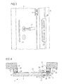
figure 3 est un détail du système de fermeture - La
figure 4 est une coupe transversale du système de porte.
- The
figure 1 is a view of a door according to the invention in its closed position - The
figure 2 is a view of a door according to the invention in its open position - The
figure 3 is a detail of the closure system - The
figure 4 is a cross section of the door system.
On se réfère à la
La
De manière particulièrement avantageuse, le cadre dormant (5) ne pénètre pas dans la baie mais est monté contre le mur (9) dans laquelle est ménagée cette ouverture. Ceci offre plusieurs avantages. En premier lieu, l'ensemble selon l'invention peut être posé après la fin des travaux. De manière avantageuse, il est possible de poser le bloc-porte selon l'invention après la mise en place des plinthes ce qui permet d'éviter une intervention supplémentaire d'adaptation des plinthes. A cet effet, le cadre dormant (5) selon l'invention présentera, de préférence, une découpe au niveau de ses montants verticaux sur la face arrière destinée à être posée contre le mur (9). Lesdites découpes sont de taille et de forme adaptée pour permettre le passage des plinthes. Un autre avantage du bloc porte (1) selon l'invention est qu'il n'est plus nécessaire de s'assurer que les jambages de la baie destinés à recevoir la porte soient parfaitement verticaux. Dans le cas d'une rénovation d'immeuble, il arrive en effet que les jambages des ouvertures de porte ne soient pas parfaitement verticaux. Ce manque de verticalité doit être rattrapé lorsque le châssis de la porte est monté à défaut sinon de ne pas pouvoir fermer correctement la porte. De même, il n'est plus obligatoire d'avoir un dimensionnement exact de la baie par rapport au cadre dormant (5), une certaine tolérance dans les côtes est rendue possible. D'ailleurs, de préférence, l'espacement entre les montants verticaux du cadre est inférieur à la largeur de la baie et le cadre dormant (5) est posé à cheval sur la baie. Le bloc-porte (1) selon l'invention permet donc de s'affranchir au moment de sa pose de certaines des contraintes liées à la baie ce qui rend sa pose facilitée. Néanmoins, pour des raisons esthétiques, et comme illustré à la
Selon l'invention donc est ainsi qu'illustré à la
En se référant à la
Comme on peut le constater, contrairement à la pratique du métier où le pêne est monté saillant et se meut afin d'entrer ou de sortir du cadre dormant, l'invention propose de mouvoir un pêne (19) confiné dans l'ouvrant afin de permettre à la gâche (25) d'entrer ou de sortir de l'ouvrant (3).As can be seen, contrary to the practice of the profession where the bolt is projecting and moves to enter or exit the frame, the invention proposes to move a bolt (19) confined in the opening to allow the striker (25) to enter or exit the opening (3).
Lorsqu'il utilise un pêne à demi-tour, l'homme du métier verra l'avantage à placer la face biseautée du pêne (19) en regard de l'évidement (21) en vue de sa coopération avec la gâche (25).When using a latch bolt, the skilled person will see the advantage of placing the beveled face of the bolt (19) facing the recess (21) for its cooperation with the latch (25) .
Selon une mise en oeuvre préférée de l'invention, la gâche (25) présente deux bouches (27) et est apte à coopérer avec deux pênes portés par la serrure (15). De préférence au moins un des pênes est un pêne ordinaire permettant le verrouillage de la porte au moyen d'une clef.According to a preferred embodiment of the invention, the striker (25) has two mouths (27) and is adapted to cooperate with two bolts carried by the lock (15). Preferably at least one of the bolts is an ordinary bolt for locking the door by means of a key.
Comme on l'aura compris le procédé de pose d'un ensemble selon l'invention est simplifié par rapport à la pose d'une porte ou d'une fenêtre selon l'art antérieur.
En effet, la pose d'un ensemble (1) selon l'invention comprend les étapes suivantes :
- positionnement de l'ensemble (1) autour d'une baie pratiquée dans un mur (9), de préférence de telle sorte à ce que l'ensemble (1) ne pénètre pas dans la baie du mur (9) ;
- fixation de l'ensemble (1) sur la face dudit mur (9).
Indeed, the installation of an assembly (1) according to the invention comprises the following steps:
- positioning the assembly (1) around a bay made in a wall (9), preferably so that the assembly (1) does not enter the wall bay (9);
- fixing the assembly (1) on the face of said wall (9).
La fixation du cadre (5) sur le mur (9) peut se faire par collage mais également, ou de manière complémentaire par le biais d'une fixation mécanique, par exemple au moyen de vis. Dans un tel cas, pour des raisons esthétiques, on aura avantage à masquer ces moyens de fixations au moyen d'une baguette (35) posée sur le cadre (5). De préférence ladite baguette (35) permet également de masquer le moyen de fixation de la gâche (25) sur le cadre.The fixing of the frame (5) on the wall (9) can be done by gluing but also, or in a complementary manner by means of a mechanical attachment, for example by means of screws. In such a case, for aesthetic reasons, it will be advantageous to mask these fastening means by means of a rod (35) placed on the frame (5). Preferably, said rod (35) also makes it possible to mask the fastening means of the striker (25) on the frame.
L'invention ne se limite pas aux modes de réalisation décrits ci-avants, donnés seulement à titre d'exemple mais englobe toutes les variantes que pourra envisager l'homme du métier dans le cadre de la définition qui en a été donnée.The invention is not limited to the embodiments described above, given only by way of example but encompasses all the variants that may be envisaged by those skilled in the art within the framework of the definition that has been given.
Claims (15)
Priority Applications (1)
| Application Number | Priority Date | Filing Date | Title |
|---|---|---|---|
| EP10175516A EP2426295A1 (en) | 2010-09-07 | 2010-09-07 | Door or window with invisible hinges and striker plate |
Applications Claiming Priority (1)
| Application Number | Priority Date | Filing Date | Title |
|---|---|---|---|
| EP10175516A EP2426295A1 (en) | 2010-09-07 | 2010-09-07 | Door or window with invisible hinges and striker plate |
Publications (1)
| Publication Number | Publication Date |
|---|---|
| EP2426295A1 true EP2426295A1 (en) | 2012-03-07 |
Family
ID=43530547
Family Applications (1)
| Application Number | Title | Priority Date | Filing Date |
|---|---|---|---|
| EP10175516A Withdrawn EP2426295A1 (en) | 2010-09-07 | 2010-09-07 | Door or window with invisible hinges and striker plate |
Country Status (1)
| Country | Link |
|---|---|
| EP (1) | EP2426295A1 (en) |
Citations (3)
| Publication number | Priority date | Publication date | Assignee | Title |
|---|---|---|---|---|
| FR2286933A1 (en) * | 1974-10-01 | 1976-04-30 | Gardenghi Aldo | High security closure lock for doors - has vertically mobilised inverted L-shaped bolt which engages slot in horizontal catch plate |
| DE2912627A1 (en) * | 1979-03-30 | 1980-10-02 | Salice Gmbh | HIDDEN HINGE FOR DOORS, FLAPS OR THE LIKE. |
| DE202009010049U1 (en) | 2009-07-24 | 2009-10-08 | Budak System | closure device |
-
2010
- 2010-09-07 EP EP10175516A patent/EP2426295A1/en not_active Withdrawn
Patent Citations (3)
| Publication number | Priority date | Publication date | Assignee | Title |
|---|---|---|---|---|
| FR2286933A1 (en) * | 1974-10-01 | 1976-04-30 | Gardenghi Aldo | High security closure lock for doors - has vertically mobilised inverted L-shaped bolt which engages slot in horizontal catch plate |
| DE2912627A1 (en) * | 1979-03-30 | 1980-10-02 | Salice Gmbh | HIDDEN HINGE FOR DOORS, FLAPS OR THE LIKE. |
| DE202009010049U1 (en) | 2009-07-24 | 2009-10-08 | Budak System | closure device |
Similar Documents
| Publication | Publication Date | Title |
|---|---|---|
| FR2912180A1 (en) | SLIDING DOOR OR WINDOW CHASSIS HAVING A VERTICAL SIDE OPENING CACHE. | |
| FR2971289A1 (en) | Access door system for allowing access through e.g. airtight ceiling of dwelling, has plate supported on splice plate, and flexible joint arranged on inner face of spillplate and compressed through locking unit, in locking position | |
| EP1574657A2 (en) | Device preventing lifting of doors | |
| CH652167A5 (en) | AERATOR. | |
| EP2426295A1 (en) | Door or window with invisible hinges and striker plate | |
| CA2990896C (en) | Seal with magnetic fastening | |
| FR2950100A1 (en) | Sliding joinery work device for e.g. window, created in wall of e.g. domestic building, has opening frame whose end and central posts are formed of aluminum parts, where bases of posts form central cavity divided by bar equipped with tabs | |
| FR3009332A1 (en) | CARPENTRY HAVING A GLASS AND INSULATING GLAZING WITH A BLADE OF AIR BETWEEN THEM, ALLOWING THE COMMUNICATION OF THE BLADE OF AIR WITH EXTERNAL AIR EXTERIOR | |
| FR2978482A1 (en) | Closure door for closing longitudinal outlet of recess of tunnel-shaped casing that is utilized for installing e.g. window, has two elements slidably mounted to each other so as to change width of closure door | |
| EP0866204B1 (en) | Burglar-proof locking device for a roller shutter cabinet | |
| FR2967196A1 (en) | Roller blind box for placing above joinery work in building to place e.g. joinery element, has effort collecting unit including fixing element for fixing upper cross beam, where collecting unit is connected to rear face | |
| FR2912175A1 (en) | LOCKED DOOR OR WINDOW FRAME COMPRISING A FRAME AND AT LEAST ONE SLIDING OPENING. | |
| FR2743388A1 (en) | Lock for window or door | |
| BE1015014A4 (en) | FITTING LOCK OPENING HAVING MEANS FOR FIXING SUPPORT INTERIOR AND EXTERIOR AND OPENING shifted EQUIPPED WITH BRACKET AS. | |
| FR2969205A1 (en) | SHUTTER CASE | |
| FR3029557B1 (en) | CARPENTRY ELEMENT | |
| FR3133212A1 (en) | Fire-resistant and flame-resistant carpentry | |
| FR2986259A1 (en) | CARPENTRY PIECE OF THE POROUS TYPE OR WINDOW REMOVABLE MULTILAYER | |
| FR2771128A1 (en) | Wedge for keeping building window open | |
| EP3401490B1 (en) | Door shielding structure and armor block using such a structure | |
| EP0147448A1 (en) | Safety door unit. | |
| EP1431479B1 (en) | Fitting sling door, sliding window or similar | |
| FR2689172A1 (en) | Door and frame assembly, designed to resist attempted break-in - has tongue and groove along hinged side of door and frame opposite side made with angled surfaces, allowing door to open outwards | |
| FR2783555A1 (en) | Door edge seal which prevents finger pinching, e.g. for sliding or swinging fire doors has edges with inserts engaging with retaining elements | |
| FR3040417B1 (en) | METHOD FOR FIXING A DOOR THRESHOLD AND ASSEMBLY FOR ITS IMPLEMENTATION |
Legal Events
| Date | Code | Title | Description |
|---|---|---|---|
| AK | Designated contracting states |
Kind code of ref document: A1 Designated state(s): AL AT BE BG CH CY CZ DE DK EE ES FI FR GB GR HR HU IE IS IT LI LT LU LV MC MK MT NL NO PL PT RO SE SI SK SM TR |
|
| AX | Request for extension of the european patent |
Extension state: BA ME RS |
|
| PUAI | Public reference made under article 153(3) epc to a published international application that has entered the european phase |
Free format text: ORIGINAL CODE: 0009012 |
|
| STAA | Information on the status of an ep patent application or granted ep patent |
Free format text: STATUS: THE APPLICATION IS DEEMED TO BE WITHDRAWN |
|
| 18D | Application deemed to be withdrawn |
Effective date: 20120908 |