EP2426256A1 - Biegeausgleichswalze für eine Papier- oder Kartonmaschine - Google Patents
Biegeausgleichswalze für eine Papier- oder Kartonmaschine Download PDFInfo
- Publication number
- EP2426256A1 EP2426256A1 EP11175685A EP11175685A EP2426256A1 EP 2426256 A1 EP2426256 A1 EP 2426256A1 EP 11175685 A EP11175685 A EP 11175685A EP 11175685 A EP11175685 A EP 11175685A EP 2426256 A1 EP2426256 A1 EP 2426256A1
- Authority
- EP
- European Patent Office
- Prior art keywords
- pressure
- pressure chamber
- roller
- roller according
- yoke
- Prior art date
- Legal status (The legal status is an assumption and is not a legal conclusion. Google has not performed a legal analysis and makes no representation as to the accuracy of the status listed.)
- Granted
Links
- 239000000123 paper Substances 0.000 title 1
- 239000011087 paperboard Substances 0.000 title 1
- 239000012530 fluid Substances 0.000 claims abstract description 45
- 238000013016 damping Methods 0.000 description 12
- 238000005452 bending Methods 0.000 description 10
- 125000006850 spacer group Chemical group 0.000 description 3
- 238000005253 cladding Methods 0.000 description 2
- 239000012528 membrane Substances 0.000 description 2
- 230000010355 oscillation Effects 0.000 description 2
- 230000010349 pulsation Effects 0.000 description 2
- 230000006399 behavior Effects 0.000 description 1
- 238000006243 chemical reaction Methods 0.000 description 1
- 238000004891 communication Methods 0.000 description 1
- 230000005489 elastic deformation Effects 0.000 description 1
- 230000005284 excitation Effects 0.000 description 1
- 230000002349 favourable effect Effects 0.000 description 1
- 239000002657 fibrous material Substances 0.000 description 1
- 238000002955 isolation Methods 0.000 description 1
- 239000000463 material Substances 0.000 description 1
- 230000013011 mating Effects 0.000 description 1
- 230000003534 oscillatory effect Effects 0.000 description 1
- 230000000737 periodic effect Effects 0.000 description 1
- 230000002093 peripheral effect Effects 0.000 description 1
- 230000002265 prevention Effects 0.000 description 1
- 230000003313 weakening effect Effects 0.000 description 1
Images


Classifications
-
- F—MECHANICAL ENGINEERING; LIGHTING; HEATING; WEAPONS; BLASTING
- F16—ENGINEERING ELEMENTS AND UNITS; GENERAL MEASURES FOR PRODUCING AND MAINTAINING EFFECTIVE FUNCTIONING OF MACHINES OR INSTALLATIONS; THERMAL INSULATION IN GENERAL
- F16C—SHAFTS; FLEXIBLE SHAFTS; ELEMENTS OR CRANKSHAFT MECHANISMS; ROTARY BODIES OTHER THAN GEARING ELEMENTS; BEARINGS
- F16C13/00—Rolls, drums, discs, or the like; Bearings or mountings therefor
- F16C13/02—Bearings
- F16C13/022—Bearings supporting a hollow roll mantle rotating with respect to a yoke or axle
- F16C13/024—Bearings supporting a hollow roll mantle rotating with respect to a yoke or axle adjustable for positioning, e.g. radial movable bearings for controlling the deflection along the length of the roll mantle
- F16C13/026—Bearings supporting a hollow roll mantle rotating with respect to a yoke or axle adjustable for positioning, e.g. radial movable bearings for controlling the deflection along the length of the roll mantle by fluid pressure
- F16C13/028—Bearings supporting a hollow roll mantle rotating with respect to a yoke or axle adjustable for positioning, e.g. radial movable bearings for controlling the deflection along the length of the roll mantle by fluid pressure with a plurality of supports along the length of the roll mantle, e.g. hydraulic jacks
Definitions
- the invention relates to a roller, in particular for a paper or board machine, with a circumferential roll shell and a fixed yoke, which passes through the roll shell axially, the roll shell by the pressure in at least two pressure chambers radially outwardly resilient, the pressure chambers with in at least one axial bore in the yoke introduced pressure fluid lines are connected, and wherein at least one pressure chamber is connected via at least one connection with at least one pressure chamber having a variable volume.
- Such rolls are used as bending compensating rolls, as floating rolls or as shoe rolls for forming a nip with a counter roll.
- a fibrous material web usually a paper or board web guided and applied in the nip with increased pressure and optionally elevated temperature.
- the bending compensation rollers may have a bore in the yoke, in which a compact tube bundle is inserted as pressure fluid lines. Each of the tubes of the tube bundle is then in communication with a pressure chamber.
- a pressure chamber To illustrate an exemplary structure is the EP 1 380 762 B1 called.
- the roller and in particular the roll shell is subjected during operation, for example, by inhomogeneities, anisotropies or geometry errors, but also by paper thickness fluctuations with excitation forces, which causes a swinging of the roll shell cause.
- the resulting oscillating motion is usually so small that it does not disturb immediately.
- these oscillatory movements are reflected in the roll shell after a longer period, which leads to a further increase in vibration. This manifests itself on the one hand as acoustic vibrations, ie in an increased sound level, but can also lead to periodic thickness variations of the material web, the so-called barring phenomenon.
- three particularly pronounced natural frequencies can be measured in a calender with a mating roll and a roll.
- a particularly low natural frequency in the order of 10 to 40 Hz is excited by the rotational frequency of the roller or the counter-roller, so that the roller and the counter-roller oscillate in phase.
- a natural frequency is measured whose size is 100 - 300 Hz. This is an antiphase oscillation between roller and counter-roller, which originates mainly from the Jocheigenfrequenz.
- the third striking natural frequency is 500 to 800 Hz and also describes an antiphase oscillation of roller and counter roll, here dominated by the contact own frequency of the shell of the roller.
- the vibration of the roll mantle is transmitted either directly or by a support element to a pressure medium arranged in the pressure chamber, which is thereby pushed back and forth over the throttle point.
- vibration energy is removed from the system by friction in the throttle point, so that there is a damping of the vibration.
- the throttle point must be designed so that enough oil can pulsate through the throttle point.
- a bending compensating roller has been proposed in which the pressure chamber is initially connected via throttle points to a pressure chamber, wherein the pressure chamber is connected via a throttle point to a pressure fluid line. Between the pressure fluid line and the pressure chamber so a pressure chamber is arranged in series, which causes isolation of the pressure fluid line.
- the pressure chamber may have a partially elastic boundary wall, by the elastic deformation of a further vibration damping is achieved.
- the invention is therefore an object of the invention to provide a bending compensating roll, can be provided in the pressure chambers or storage in a simple manner even with existing rollers near the pressure chamber, in such a way that the pressure chambers or memory, the bending behavior of the yoke or not only insignificantly influence.
- this object is achieved in a roller of the type mentioned above in that the at least one pressure chamber and the pressure fluid lines are accommodated adjacent in the axial bore.
- the pressure chamber is housed in an existing cavity of the yoke anyway.
- the pressure chambers can be brought relatively close to the pressure chambers, and even with rollers already in use, where the pressure chambers are to be introduced with the shortest possible conversion in the roll.
- the pressure chambers themselves are arranged as usual in the yoke, wherein in each pressure chamber, a support element is guided, which can be pressed by a pressure in the pressure chamber with a Anlegeseite against the roll shell.
- the support element is generally feasible radially in the pressure chamber and limits one side of the pressure chamber. It can be between the support member and a peripheral surface of the Pressure chamber to be arranged a seal.
- the support element forms one side of the pressure chamber.
- oil chambers On the abutment side of the support member, oil chambers may be formed which serve to form an oil film between the abutment side of the support member and an inner side of the roll shell. This oil film may be, for example 20 to 50 microns thick and is very stiff, so that there is almost no vibration damping.
- the vibrations of the roll mantle are thus transferred directly to the support element which swings correspondingly with the roll shell within the pressure chamber and thus transmits the vibration to the pressure medium arranged in the pressure chamber.
- the support member may be formed as a shoe shoe shoe, but it can also be arranged axially adjacent to each other a plurality of support elements in a corresponding plurality of pressure chambers.
- the arrangement of the pressure chamber in the yoke can be relatively well sealed to the outside.
- the pressure fluid lines are located in an axial bore in the yoke.
- At least one pressure chamber and the pressure fluid lines form a structural unit. Such a unit can be inserted after the pre-assembly of the axial end of the yoke ago in the axial bore.
- a pressure chamber and the pressure fluid lines are hydraulically coupled in the axial bore.
- the pressure chamber can then be hydraulically linked without further measures with the pressure chamber. It is favorable if the pressure chamber is within a membrane reservoir. Diaphragm stores are often round and build relatively small. Thereby can also be kept the diameter of the axial bore in the usual framework.
- the discs have a radial bore which is aligned with the pressure chamber and which communicates at least with a pressurized fluid line.
- a radial bore which is aligned with the pressure chamber and which communicates at least with a pressurized fluid line.
- the pressure chamber (also) is connected to the disc. This makes the unit compact and stable.
- a throttle point is arranged.
- the throttles work by the resulting friction of the pressure fluid as "energy shredder” and dampen in this way vibrations of the roller.
- two throttles are provided, namely one in front of the pressure chamber and one in the pressure fluid line, so can by the vibrations of the Roll mantle moving hydraulic fluid can be pushed back and forth not only on the first throttle point, but also via the second throttle point in at least one pressure chamber whose volume is changed by the corresponding pressure fluctuations.
- the special feature of two reactors is that you can influence the Jöchigenigenfrequency and the contact eigenfrequency of the shell largely independent throttling on the respective throttle resistors. This reduces the occurrence of barring and extends the life of the roller.
- a plurality of pressure chambers in the axial direction of the roller are arranged side by side.
- the storage tanks can then be connected to different pressure chambers.
- the pressure chambers can all be connected to different discs and communicate with them via an associated pressure chamber.
- the pressure chamber may, for example, be located in a diaphragm accumulator, whereby beyond the diaphragm there is a chamber which is generally gas-charged and via whose gas pressure and gas volume it is possible additionally to influence the vibration damping.
- a hermetically sealed design of the chamber has the advantage that a virtually maintenance-free operation is possible.
- a number and / or a cross-sectional area and / or a length of the throttle point are variable with at least one adjusting element, which is designed in particular as a hydraulic, electrical, magnetic or piezoelectric actuator. This makes it possible to subsequently tune the system to individual frequencies. It is also possible to attenuate a first frequency band over a certain period of time and another frequency band in a later period. Overall, the Damping be maximized, so that ultimately extends the life of the roller.
- At least one vibration sensor is arranged on the roll shell and / or on the yoke and / or on the support element and / or in the pressure chamber.
- the vibration of the roll shell can be determined directly and use, for example, to control the actuator. This makes it possible to maximize damping.
- the roller 10 has a continuous and non-rotatably to be stored yoke 14.
- a jacket 12 is rotatably mounted on this yoke 14.
- This jacket 12 presses, for example, in a calender against a counter-roller, not shown, and thus forms a specialistssnip for a Fibrous web.
- a number of hydraulic support elements 16 are supported on the yoke, which act exactly in the direction of the nip.
- support elements which apply forces in the opposite direction, are also provided for adjusting the deflection of the jacket 12.
- pressure fluid lines 24 The supply of the pressurized fluid to a pressure chamber under the support element via pressure fluid lines 24.
- each support element has - as in Fig. 3 shown - a separate pressure fluid line 24 or more support elements are supplied together in a so-called zone by a pressure fluid line 24.
- All of these pressure fluid lines 24 are housed as tubes in an axial bore 20 in the yoke 14.
- return lines 26 which must be accommodated in the axial bore 20.
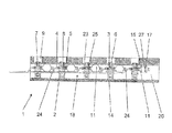
- Fig. 1 Shown is merely a longitudinal section through a yoke portion of a bending compensating roller 1 according to the invention.
- Sheath 2 and supporting elements 16 have been omitted for the sake of clarity, because they anyway as used in a conventional bending compensating roll 10.
- the yoke 14 includes cylinder bores 9 in which support members 16, as in Fig. 3 shown can be used.
- the cylinder bore 9 which is the radially inner region below the support member is formed as a pressure chamber 8.
- a pressure fluid inlet At the bottom of the cylinder bore 9 is a pressure fluid inlet. 7
- the yoke 14 is centrally provided with an axial bore 20 in the relatively uncritical region, as far as the moments of resistance.
- discs 2 are arranged. These discs 2 are so thick that at least one radial bore 3 can be introduced. It is advantageous if the side of the radial bore 3 still has room for a seal.
- a pressurized fluid line 24 is attached.
- a first throttle point 23 is integrated in the connection.
- a pressure accumulator 11 is attached. As can be seen in the cut last memory 11 of the displayed series of pressure accumulators, it has a pressure chamber 15 whose volume is variable.
- a chamber 17 is separated from the pressure chamber by an elastic and flexible wall 27.
- a gas pressure which co-determines the volume of the pressure chamber 15 in dependence on the instantaneous pressure of the pressure fluid filling it.
- an "energy-absorbing" second throttle restriction 25 is advantageously integrated.
- the pressure medium located in the pressure chamber 8 back and forth over the throttle point 23.
- the system In the throttle body 23 the system is deprived of energy by friction. This results in a vibration damping.
- the size of the throttle body 23 has a great influence on the frequency at which an effective vibration damping takes place. If the throttle point 23 is too small, only a small amount of oil can pass through the throttle point, so that any rapid lowering of the jacket 12, which may be necessary during operation, is not possible. If the throttle point 23 is too wide, the flow resistance caused by it is low, so that only a small attenuation can be achieved. In a roller in operation, an overall cross-section has been found in the throttle point of 5-10 mm 2 in the form of 16 throttle holes as a particularly effective against the Jocheigenfrequenzen damping value.
- Each pressure chamber 15 forms with a chamber 17, a second throttle body 25 and a wall 27 between the chamber and the pressure chamber each have a pulsation damper, which can be tuned to a specific frequency.
- a pulsation damper which can be tuned to a specific frequency.
- the radial bore 3 is provided with a sealed adapter 6.
- a flow path for the pressure fluid from the pressure fluid line 24 to the pressure chamber 8 and the pressure chamber 15 is created, as needed via a first and / or a second throttle body 23, 25th
- Fig. 1 show also connection possibilities and radial bores on the side facing away from the nip (in the drawing below), which are not used there however.
- Fig. 2 can be particularly well illustrated that all "innards" of the axial bore 20 may consist of a preassembled unit 18 of pipes 24, 26 and storage 11.
- the Fig. 2 shows exactly such a preassembled unit 18.
- the discs In order to allow all pressure fluid lines 24 to enter only one end of the roll in the axial bore 20, the discs have 2 recesses 13 so that discs 2 at the other end of the roller via pressure fluid lines 24 can be reached and so can be supplied with pressurized fluid. The discs thus receive a bone-like shape.
- the threaded rod 21 in each case passes through a hole in each disc 2 and is fixed by the nuts.
- a plurality of spacers 19 can be used here, if necessary, to prevent rotation of the discs against each other. However, they must be arranged so that a certain Deflection of the yoke due to the forces in the nip does not cause problems.
Landscapes
- Engineering & Computer Science (AREA)
- General Engineering & Computer Science (AREA)
- Physics & Mathematics (AREA)
- Fluid Mechanics (AREA)
- Mechanical Engineering (AREA)
- Paper (AREA)
- Rolls And Other Rotary Bodies (AREA)
Abstract
Description
- Die Erfindung betrifft eine Walze, insbesondere für eine Papier- oder Kartonmaschine, mit einem umlaufenden Walzenmantel und einem feststehenden Joch, das den Walzenmantel axial durchsetzt, wobei der Walzenmantel durch den Druck in mindestens zwei Druckkammern radial nach außen belastbar ist, wobei die Druckkammern mit in wenigstens einer Axialbohrung im Joch eingebrachten Druckfluidleitungen verbunden sind, und wobei mindestens eine Druckkammer über mindestens einen Anschluss mit mindestens einem Druckraum verbunden ist, der ein veränderbares Volumen aufweist.
- Derartige Walzen werden als Biegeausgleichswalzen, als schwimmende Walzen oder als Schuhwalzen zur Bildung eines Nips mit einer Gegenwalze eingesetzt. Durch den Nip wird eine faserförmige Materialbahn, in der Regel eine Papier- oder Kartonbahn geführt und im Nip mit erhöhtem Druck und gegebenenfalls erhöhter Temperatur beaufschlagt.
- Die Biegeausgleichswalzen können eine Bohrung im Joch aufweisen, in die als Druckfluidleitungen ein kompaktes Rohrbündel eingeschoben wird. Jedes der Rohre des Rohrbündels steht dann mit einer Druckkammer in Verbindung. Zur Veranschaulichung eines beispielhaften Aufbaus sei die
EP 1 380 762 B1 genannt. - Die Walze und insbesondere der Walzenmantel wird im Betrieb beispielsweise durch Inhomogenitäten, Anisotropien oder Geometriefehlern, aber auch durch Papierdickenschwankungen mit Erregerkräften beaufschlagt, die ein Schwingen des Walzenmantels bewirken. Die resultierende Schwingbewegung ist in der Regel so klein, dass sie nicht unmittelbar stört. Allerdings prägen sich diese Schwingungsbewegungen nach einem längeren Zeitraum in den Walzenmantel ein, was zu einer weiteren Schwingungsverstärkung führt. Dies macht sich zum einen als akustische Schwingungen bemerkbar, also in einem erhöhten Schallpegel, kann aber auch zu periodischen Dickenschwankungen der Materialbahn führen, der so genannten Barring-Erscheinung.
- In der Regel sind in einem Kalander mit einer Gegenwalze und einer besagten Walze drei besonders ausgeprägte Eigenfrequenzen messbar. Eine besonders niedrige Eigenfrequenz in der Größenordnung von 10 bis 40 Hz wird durch die Drehfrequenz der Walze oder der Gegenwalze angeregt, so dass die Walze und die Gegenwalze gleichphasig schwingen. Des Weiteren ist eine Eigenfrequenz zu messen, deren Größe bei 100 - 300 Hz liegt. Hier handelt es sich um eine gegenphasige Schwingung zwischen Walze und Gegenwalze, die vorwiegend aus der Jocheigenfrequenz herrührt. Die dritte markante Eigenfrequenz liegt bei 500 bis 800 Hz und beschreibt ebenfalls ein gegenphasiges Schwingen von Walze und Gegenwalze, wobei hier die Kontakteigenfrequenz des Mantels der Walze dominiert.
- Die Schwingung des Walzenmantels wird entweder direkt oder durch ein Stützelement auf ein in der Druckkammer angeordnetes Druckmittel übertragen, das dadurch über die Drosselstelle hin- und hergeschoben wird. Dabei wird in der Drosselstelle durch Reibung dem System Schwingungsenergie entzogen, so dass eine Dämpfung der Schwingung erfolgt. Die Drosselstelle muss dabei so ausgelegt sein, dass genügend Öl über die Drosselstelle pulsieren kann.
- Um eine Rückkopplung auf die Druckfluidleitung zu vermindern, ist in
EP 1 731 668 A1 eine Biegeausgleichswalze vorgeschlagen worden, bei der die Druckkammer über Drosselstellen zunächst mit einem Druckraum verbunden ist, wobei der Druckraum über eine Drosselstelle an einer Druckfluidleitung angeschlossen ist. Zwischen der Druckfluidleitung und der Druckkammer ist also in Reihe ein Druckraum angeordnet, der eine Isolierung der Druckfluidleitung bewirkt. Dabei kann der Druckraum eine teilweise elastische Begrenzungswand aufweisen, durch deren elastische Verformung eine weitere Schwingungsdämpfung erreicht wird. - In
DE 10 2007 051 395 A1 ist vorgeschlagen, die Druckkammer einer Durchbiegungseinstellwalze mit Hilfe einer Membran in zwei Kammern aufzuteilen, wobei die einem Stützelement zugewandte Druckkammer über eine Drosselstelle mit einer Druckfluidleitung verbunden ist und die durch die elastische Wand von der Druckkammer abgetrennte Kammer mit einem kompressiblen Medium gefüllt ist. Das kompressible Medium, beispielsweise ein Gas, kann dabei über eine Anschlussleitung in die Kammer eingebracht werden. Bei dieser Lösung erfolgt zum einen eine Schwingungsdämpfung über die Hin- und Herbewegung des Druckmittels über die Drosselstelle und zum anderen durch die Bewegung der elastischen Wand, die die Druckkammer teilweise begrenzt. - Was den Zeichnungen der beiden letztgenannten Anmeldungen (
EP 1 731 668 A1 undDE 10 2007 051 395 A1 ) nicht ohne Weiteres zu entnehmen ist, ist der Nachteil, dass bei derartigen Druckkammern das Volumen in der Regel vergrößert werden muss, um ausreichend Platz für einen großen Druckraum zu schaffen, dessen Speicherkapazität die geforderten Belange erfüllt. Eine Vergrößerung der Druckkammern einerseits, aber auch eine separate Anbringung vom Druckräumen im äußeren Bereich des Jochs andererseits führt zu einer deutlichen Erniedrigung des Widerstandsmomentes (Biegung) des Jochs. Dies ist bei den heutigen Längen und Kräften durch die Gegenwalzen selbstverständlich unerwünscht. - Der Erfindung liegt daher die Aufgabe zugrunde, eine Biegeausgleichswalze zu schaffen, bei der Druckräume oder -speicher auf einfache Weise auch bei bereits bestehenden Walzen nahe der Druckkammer vorgesehen werden können, und zwar so, dass die Druckräume oder -speicher das Biegeverhalten des Jochs nicht oder nur unwesentlich beeinflussen.
- Erfindungsgemäß wird diese Aufgabe bei einer Walze der eingangs genannten Art dadurch gelöst, dass der mindestens eine Druckraum und die Druckfluidleitungen benachbart in der Axialbohrung untergebracht sind.
- Bei dieser Lösung wird der Druckraum in einem sowieso vorhandenen Hohlraum des Joch mit untergebracht. Es sind also keine das Joch schwächende zusätzliche Aussparungen, insbesondere im radial äußeren Bereich vorzusehen. Es ist auch vorteilhaft, dass die Druckräume relativ nah an die Druckkammern herangebracht werden können, und das sogar bei bereits im Einsatz befindlichen Walzen, wo die Druckräume mit einem möglichst kurzen Umbau in die Walze eingebracht werden sollen.
- Die Druckkammern selbst sind wie üblich im Joch angeordnet, wobei in jeder Druckkammer ein Stützelement geführt ist, das durch einen Druck in der Druckkammer mit einer Anlegeseite gegen den Walzenmantel drückbar ist. Das Stützelement ist dabei in der Regel radial in der Druckkammer führbar und begrenzt eine Seite der Druckkammer. Dabei kann zwischen dem Stützelement und einer Umfangsfläche der Druckkammer eine Dichtung angeordnet sein. Das Stützelement bildet eine Seite der Druckkammer. An der Anlegeseite des Stützelements können Ölkammern ausgebildet sein, die zum Ausbilden eines Ölfilms zwischen der Anlegeseite des Stützelements und einer Innenseite des Walzenmantels dienen. Dieser Ölfilm kann beispielsweise 20 bis 50 µm dick sein und ist sehr steif, so dass darüber nahezu keine Schwingungsdämpfung erfolgt. Die Schwingungen des Walzenmantels werden also direkt auf das Stützelement übertragen, das entsprechend mit dem Walzenmantel innerhalb der Druckkammer schwingt und so die Schwingung auf das in der Druckkammer angeordnete Druckmedium überträgt. Das Stützelement kann als Schuh einer Schuhwalze ausgebildet sein, es können aber auch mehrere Stützelemente in entsprechend vielen Druckkammern axial nebeneinander angeordnet sein. Durch die Anordnung der Druckkammer im Joch kann diese nach außen relativ gut abgedichtet werden. Die Druckfluidleitungen liegen in einer Axialbohrung im Joch.
- Es ist von Vorteil, wenn wenigstens ein Druckraum und die Druckfluidleitungen eine Baueinheit bilden. Eine solche Baueinheit lässt sich nach der Vormontage vom axialen Ende des Jochs her in die Axialbohrung einschieben.
- Vorzugsweise sind in der Axialbohrung ein Druckraum und die Druckfluidleitungen hydraulisch gekoppelt. Dadurch ist wie bei herkömmlichen Rohrbündeln nur die Schaffung einer einzigen Verbindung mit der Druckkammer herzustellen. Die Druckkammer kann dann ohne weitere Maßnahmen auch mit dem Druckraum hydraulisch verknüpft sein. Günstig ist es, wenn der Druckraum innerhalb eines Membranspeichers ist. Membranspeicher sind häufig rund und bauen relativ klein. Dadurch kann auch der Durchmesser der Axialbohrung im üblichen Rahmen gehalten werden.
- Es ist von Vorteil, wenn voneinander beabstandete Scheiben vorgesehen sind, in denen die Druckfluidleitungen gelagert sind. Dabei sollten sich die Scheiben zumindest teilweise mit ihrem Außenumfang an der Wandung der Axialbohrung abstützen. Dadurch wird eine eventuelle Baueinheit relativ steif und die Druckfluidleitungen werden auch im Betrieb schwingungssicher gehalten.
- Bevorzugt ist, dass die Scheiben eine Radialbohrung aufweisen, die zu der Druckkammer ausgerichtet ist und die zumindest mit einer Druckfluidleitung in Verbindung steht. Eine derartige Anordnung ermöglicht es, die Radialbohrung beispielsweise über einen einschraubbaren Adapter mit der Druckkammer zu verbinden. Auf diese Weise ist die Versorgung der Druckkammer aus der Druckfluidleitung sicher gestellt.
- Besonders bevorzugt ist es, wenn der Druckraum (ebenfalls) an der Scheibe angeschlossen ist. Dadurch wird die Baueinheit kompakt und stabil.
- Vorteilhaft ist es, wenn zur Schwingungsvermeidung im Anschluss oder dem folgenden Kanal zu wenigstens einem Druckraum und/oder in der Druckfluidleitung zu wenigstens einer Druckkammer und/oder in einem Adapter eine Drosselstelle angeordnet ist. Die Drosseln arbeiten durch die entstehende Reibung des Druckfluids als "Energievernichter" und dämpfen auf diese Weise Vibrationen der Walze. Wenn zwei Drosseln vorgesehen sind, nämlich eine vor dem Druckraum und eine in der Druckfluidleitung, so kann die durch die Schwingungen des Walzenmantels bewegte Hydraulikflüssigkeit nicht nur über die erste Drosselstelle hin- und hergeschoben werden, sondern auch über die zweite Drosselstelle in mindestens einen Druckraum, dessen Volumen sich durch die entsprechenden Druckschwankungen verändert. Das besondere an zwei Drosseln ist dabei, dass man über die jeweiligen Drosselwiderstände die Jocheigenfrequenz und die Kontakteigenfrequenz des Mantels weitgehend unabhängig voneinander drosselnd beeinflussen kann. Dadurch wird das Auftreten von Barring vermindert und eine Standzeit der Walze verlängert.
- Vorzugsweise sind mehrere Druckräume in Axialrichtung der Walze nebeneinander angeordnet. Die Speicher sind dann mit verschiedenen Druckkammern verbindbar. Die Druckräume können alle an unterschiedliche Scheiben angeschlossen werden und über sie mit einer zugehörigen Druckkammer in Verbindung stehen. Die Druckkammer kann sich beispielsweise in einem Membranspeicher befinden, wobei jenseits der Membran eine in der Regel gasbeaufschlagte Kammer existiert, über deren Gasdruck und Gasvolumen man zusätzlich Einfluss auf die Schwingungsdämpfung nehmen kann. Eine hermetisch dichte Ausbildung der Kammer hat den Vorteil, dass ein nahezu wartungsfreier Betrieb möglich ist.
- In einer bevorzugten Ausführungsform sind eine Anzahl und/oder eine Querschnittsfläche und/oder eine Länge der Drosselstelle mit mindestens einem Stellelement veränderbar, das insbesondere als hydraulisches, elektrisches, magnetisches oder piezoelektrisches Stellelement ausgebildet ist. Dadurch ist es möglich, das System nachträglich auf einzelne Frequenzen abzustimmen. Es ist auch möglich, über einen bestimmten Zeitraum ein erstes Frequenzband zu dämpfen und in einem späteren Zeitraum ein weiteres Frequenzband. Insgesamt kann die Dämpfung maximiert werden, so dass sich letztlich die Standzeit der Walze verlängert.
- Dabei ist besonders bevorzugt, dass mindestens ein Schwingungssensor am Walzenmantel und/oder am Joch und/oder am Stützelement und/oder in der Druckkammer angeordnet ist. Mit Hilfe dieses Schwingungssensors lässt sich die Schwingung des Walzenmantels direkt ermitteln und beispielsweise zur Ansteuerung des Stellelements verwenden. Dadurch ist eine Maximierung der Dämpfung möglich.
- Die Erfindung wird im Folgenden anhand eines bevorzugten Ausführungsbeispiels in Verbindung mit den Zeichnungen beschrieben. Hierin zeigen:
- Fig. 1
- einen Teillängsschnitt durch die Achse der Walze und
- Fig. 2
- einen Ausschnitt aus einer dreidimensionalen Zeichnung der Baueinheit und
- Fig. 3
- eine Walze nach dem Stand der Technik.
- Da
Fig. 1 undFig. 2 nur die erfindungswesentlichen Bauteile der Walze zeigen wird zunächst der gesamte Erfindungsgegenstand, also eine Biegeeinstellwalze, anhand der den Stand der Technik darstellendenFig. 3 erläutert. - Die Walze 10 weist ein durchgehendes und drehfest zu lagerndes Joch 14 auf. Auf diesem Joch 14 ist ein Mantel 12 drehbar gelagert. Dieser Mantel 12 drückt beispielsweise in einem Kalander gegen eine nicht dargestellte Gegenwalze und bildet so einen Behandlungsnip für eine Faserstoffbahn. Um den notwendigen geradlinigen Druck im Nip aufbringen zu können, stützen sich an dem Joch eine Reihe von hydraulischen Stützelementen 16 ab, die genau in Richtung des Nips wirken. Bei manchen Biegeeinstellwalzen sind zur Einstellung der Durchbiegung des Mantels 12 auch Stützelemente vorgesehen, die in Gegenrichtung Kräfte aufbringen.
- Durch Anregungen kommt es vor, dass der Mantel 12 im Betrieb schwingt. Diese Schwingung überträgt sich über die Stützelemente auf das Druckfluid, das jedes Stützelement ggf. mit unterschiedlichen Fluiddrücken mit Druck beaufschlagt.
- Die Heranführung des Druckfluids zu einer Druckkammer unter dem Stützelement erfolgt über Druckfluidleitungen 24. Entweder jedes Stützelement besitzt - wie in
Fig. 3 dargestellt - eine eigene Druckfluidleitung 24 oder mehrere Stützelemente werden in einer sogenannten Zone gemeinsam durch eine Druckfluidleitung 24 versorgt. Alle diese Druckfluidleitungen 24 werden als Rohre in einer Axialbohrung 20 im Joch 14 untergebracht. Hinzu kommen oft noch Rückflussleitungen 26, die in der Axialbohrung 20 untergebracht werden müssen. - Dabei hat es sich als besonders vorteilhaft herausgestellt, alle Rohrleitungen 24, 26, beispielsweise untergebracht in einem Hüllrohr 22, als eine vormontierte Einheit in die Axialbohrung 20 einschiebbar zu gestalten.
- Mit der
Fig. 1 wird jetzt das Wesentliche der Erfindung erklärt. Dargestellt ist lediglich ein Längsschnitt durch einen Jochabschnitt einer erfindungsgemäßen Biegeausgleichswalze 1. Mantel 2 und Stützelemente 16 wurden zur besseren Übersichtlichkeit weggelassen, weil sie sowieso wie bei einer herkömmlichen Biegeausgleichswalze 10 verwendet werden. Das Joch 14 enthält Zylinderbohrungen 9, in denen Stützelemente 16, wie inFig. 3 gezeigt, eingesetzt werden können. In der Zylinderbohrung 9 ist der ist der radial innen liegende Bereich unterhalb des Stützelementes als Druckkammer 8 ausgebildet. Am Boden der Zylinderbohrung 9 ist ein Druckfluideintritt 7. - Das Joch 14 ist im relativ unkritischen Bereich, was die Widerstandsmomente anbelangt, zentral mit einer Axialbohrung 20 versehen. Auf der axialen Höhe der Stützelemente sind Scheiben 2 angeordnet. Diese Scheiben 2 sind so dick, dass zumindest eine radiale Bohrung 3 eingebracht werden kann. Vorteilhaft ist es, wenn seitlich der radialen Bohrung 3 noch Platz für eine Dichtung vorhanden ist. Von beiden Seiten einer Scheibe 2 ist ein jeweils ein Anschluss 4, 5 zu erkennen. An dem einen Anschluss 4 ist eine Druckfluidleitung 24 angebracht. Mit Vorteil ist in dem Anschluss noch eine erste Drosselstelle 23 integriert. An dem anderen Anschluss 5 ist ein Druckspeicher 11 angebracht. Wie im aufgeschnittenen letzten Speicher 11 der angezeigten Reihe von Druckspeichern zu erkennen, besitzt er einen Druckraum 15, dessen Volumen variabel ist. Denn innerhalb des Speichers 11 ist eine Kammer 17 von dem Druckraum durch eine elastische und flexible Wand 27 abgetrennt. In der Kammer 17 herrscht ein Gasdruck, der das Volumen des Druckraums 15 in Abhängigkeit vom momentanen Druck des ihn füllenden Druckfluids mitbestimmt. Auch an dem zweiten Anschluss 5 ist mit Vorteil eine "energieschluckende" zweite Drosselstelle 25 integriert.
- Das in der Druckkammer 8 befindliche Druckmittel über die Drosselstelle 23 hin- und hergeschoben. In der Drosselstelle 23 wird dem System durch Reibung Energie entzogen. Dadurch erfolgt eine Schwingungsdämpfung. Die Größe der Drosselstelle 23 hat dabei großen Einfluss darauf, bei welcher Frequenz eine wirksame Schwingungsdämpfung erfolgt. Ist die Drosselstelle 23 zu klein, kann nur wenig Öl die Drosselstelle passieren, so dass ein eventuell im Betrieb notwendiges schnelles Absenken des Mantels 12 nicht möglich ist. Wenn die Drosselstelle 23 zu weit ist, ist auch der durch sie hervorgerufene Strömungswiderstand gering, so dass nur eine geringe Dämpfung erzielbar ist. Bei einer im Betrieb befindlichen Walze hat sich ein Gesamtquerschnitt in der Drosselstelle von 5-10 mm2 in Form von 16 Drosselbohrungen als ein gegen die Jocheigenfrequenzen besonders wirkungsvoll dämpfender Wert herausgestellt.
- Doch man will mit der Walze auch die Kontakteigenfrequenzen des Mantels mit der Gegenwalze dämpfen. Alleine über die Drosselstelle 23 ist dies oft nicht zu erreichen. Eine Verbesserung der Schwingungsdämpfung wird mit Hilfe des zusätzlichen Druckraums 15 erreicht. An dieser Stelle gibt es eine wesentliche Einstellmöglichkeit für die Dämpfung der höheren Frequenzen. Der Querschnitt, der zwischen dem Druckraum 15 und der Druckkammer 8 installierten zweiten Drossel 25 ist ausschlaggebend. Ein ein- bis zweifach so großer Drosselquerschnitt ist ideal geeignet, auch die hohen Schwingungsamplituden der Kontakteigenfrequenz des Mantels zu mildern.
- Jeder Druckraum 15 bildet mit einer Kammer 17, einer zweiten Drosselstelle 25 und einer Wand 27 zwischen der Kammer und dem Druckraum jeweils einen Pulsationsdämpfer, der auf eine bestimmte Frequenz abgestimmt werden kann. Durch das Vorsehen mehrerer derartiger Pulsationsdämpfer, die jeweils auf eine bestimmte Frequenz abgestimmt sind, kann dabei eine Dämpfung über ein sehr breites Frequenzband erfolgen.
- Durch den Boden der Zylinderbohrung 9 wird die radiale Bohrung 3 mit einem abgedichteten Adapter 6 versehen. Damit ist ein Fließweg für das Druckfluid von der Druckfluidleitung 24 zur Druckkammer 8 und zum Druckraum 15 geschaffen, je nach Bedarf über eine erste und/oder eine zweite Drosselstelle 23, 25.
- Die Scheiben in
Fig. 1 zeigen auch Anschlussmöglichkeiten und radiale Bohrungen auf der dem Nip abgewandten Seite (in der Zeichnung also unten), die dort allerdings nicht verwendet werden. - Mit
Fig. 2 kann besonders gut verdeutlicht werden, dass alle "Innereien" der Axialbohrung 20 aus einer vormontierten Einheit 18 aus Rohrleitungen 24, 26 und Speichern 11 bestehen kann. DieFig. 2 zeigt nämlich genau eine solche vormontierte Einheit 18. Um alle Druckfluidleitungen 24 nur von einem Walzenende aus in die Axialbohrung 20 eintreten lassen zu können, besitzen die Scheiben 2 Aussparungen 13, damit auch Scheiben 2 am anderen Ende der Walze über Druckfluidleitungen 24 erreichbar sind und so mit Druckfluid versorgt werden können. Die Scheiben erhalten dadurch eine knochenähnliche Form. - Für einen genau einzuhaltenden Abstand der Scheiben ist zumindest ein Abstandhalter 19, hier in Form einer Gewindestange 21 mit Muttern, verantwortlich. Die Gewindestange 21 durchzieht hierbei jeweils eine Bohrung in jeder Scheibe 2 und wird durch die Muttern fixiert. Selbstverständlich können hier auch mehrere Abstandhalter 19 eingesetzt werden, ggf. um eine Verdrehung der Scheiben gegeneinander zu verhindern. Allerdings müssen sie so angeordnet sein, dass eine gewisse Durchbiegung des Jochs aufgrund der Kräfte im Nip nicht zu Problemen führt.
-
- 1
- Biegeausgleichswalze nach der Erfindung
- 2
- Scheibe
- 3
- Radiale Bohrung
- 4
- Anschluss
- 5
- Anschluss
- 6
- Adapter
- 7
- Druckfluideintritt
- 8
- Druckkammer
- 9
- Zylinderbohrung
- 10
- Biegeausgleichswalze nach dem Stand der Technik
- 11
- Druckspeicher, Membranspeicher
- 12
- Mantel
- 13
- Aussparung
- 14
- Joch
- 15
- Druckraum
- 16
- Stützelement
- 17
- Kammer
- 18
- Vormontierbare Baueinheit
- 19
- Abstandhalter
- 20
- Axialbohrung
- 21
- Gewindestange
- 22
- Hüllrohr
- 23
- Erste Drosselstelle
- 24
- Rohrleitung, Druckfluidleitung
- 25
- Zweite Drosselstelle
- 26
- Rückflussleitung
- 27
- Wand
Claims (11)
- Walze, insbesondere für eine Papier- oder Kartonmaschine, mit einem umlaufenden Walzenmantel (12) und einem feststehenden Joch (14), das den Walzenmantel (12) axial durchsetzt, wobei der Walzenmantel (12) durch den Druck in mindestens zwei Druckkammern (8) radial nach außen belastbar ist, wobei die Druckkammern (8) mit in wenigstens einer Axialbohrung (20) im Joch (14) eingebrachten Druckfluidleitungen (24) verbunden sind, und wobei mindestens eine Druckkammer (8) über mindestens einen Anschluss (5) mit mindestens einem Druckraum (15) verbunden ist, der ein veränderbares Volumen aufweist, dadurch gekennzeichnet, dass der mindestens eine Druckraum (15) und die Druckfluidleitungen (24) benachbart in der Axialbohrung (20) untergebracht sind.
- Walze nach Anspruch 1, dadurch gekennzeichnet, dass wenigstens ein Druckraum (15) und die Druckfluidleitungen (24) eine Baueinheit (18) bilden.
- Walze nach Anspruch 1 oder 2, dadurch gekennzeichnet, dass in der Axialbohrung (20) ein Druckraum (15) und die Druckfluidleitungen (24) hydraulisch gekoppelt sind.
- Walze nach einem der Ansprüche 1 bis 3, dadurch gekennzeichnet, dass der Druckraum (15) innerhalb eines Membranspeichers (11) ist.
- Walze nach einem der Ansprüche 1 bis 4, dadurch gekennzeichnet, dass voneinander beabstandete Scheiben (2) vorgesehen sind, in denen die Druckfluidleitungen (24) gelagert sind.
- Walze nach Anspruch 5, dadurch gekennzeichnet, dass die Scheiben (2) eine Radialbohrung aufweisen, die zu der Druckkammer (8) ausgerichtet ist und die zumindest mit einer Druckfluidleitung (24) in Verbindung steht.
- Walze nach einem der Ansprüche 5 bis 6, dadurch gekennzeichnet, dass der Druckraum (15) an der Scheibe (2) angeschlossen ist.
- Walze nach einem der Ansprüche 1 bis 7, dadurch gekennzeichnet, dass im Anschluss (5) oder dem folgenden Kanal zu wenigstens einem Druckraum (15) und/oder in der Druckfluidleitung (24) zu wenigstens einer Druckkammer (8) und/oder in einem Adapter (6) eine Drosselstelle (23, 25) angeordnet ist.
- Walze nach einem der Ansprüche 1 bis 8, dadurch gekennzeichnet, dass mehrere Druckräume (15) in Axialrichtung der Walze (1) nebeneinander angeordnet sind.
- Walze nach einem der Ansprüche 1 bis 9, dadurch gekennzeichnet, dass eine Anzahl und/oder eine Querschnittsfläche und/oder eine Länge der Drosselstelle (23, 25) mit mindestens einem Stellelement veränderbar ist, das insbesondere als hydraulisches, elektrisches, magnetisches oder piezoelektrisches Stellelement ausgebildet ist.
- Walze nach einem der Ansprüche 1 bis 10, dadurch
gekennzeichnet, dass mindestens ein Schwingungssensor am Walzenmantel (12) und/oder am Joch (14) und/oder am Stützelement (16) und/oder in der Druckkammer (8) angeordnet ist.
Applications Claiming Priority (1)
| Application Number | Priority Date | Filing Date | Title |
|---|---|---|---|
| DE201010040149 DE102010040149A1 (de) | 2010-09-02 | 2010-09-02 | Walze für eine Papier- oder Kartonmaschine |
Publications (2)
| Publication Number | Publication Date |
|---|---|
| EP2426256A1 true EP2426256A1 (de) | 2012-03-07 |
| EP2426256B1 EP2426256B1 (de) | 2013-10-09 |
Family
ID=44653151
Family Applications (1)
| Application Number | Title | Priority Date | Filing Date |
|---|---|---|---|
| EP20110175685 Not-in-force EP2426256B1 (de) | 2010-09-02 | 2011-07-28 | Biegeausgleichswalze für eine Papier- oder Kartonmaschine |
Country Status (3)
| Country | Link |
|---|---|
| EP (1) | EP2426256B1 (de) |
| CN (1) | CN202359455U (de) |
| DE (1) | DE102010040149A1 (de) |
Citations (8)
| Publication number | Priority date | Publication date | Assignee | Title |
|---|---|---|---|---|
| US4090282A (en) * | 1976-10-19 | 1978-05-23 | Escher Wyss Limited | Deflection control device |
| WO1988003610A1 (fr) * | 1986-11-07 | 1988-05-19 | J.M. Voith Gmbh | Cylindre |
| US5800324A (en) * | 1995-06-10 | 1998-09-01 | Voith Sulzer Papiermaschinen Gmbh | Roll with vibration damper |
| WO2000009805A1 (en) * | 1998-08-14 | 2000-02-24 | Metso Paper, Inc. | Method and device for changing the natural frequency of a nip roll construction in a paper or board machine |
| EP0786054B1 (de) * | 1995-05-18 | 2002-01-02 | Metso Paper, Inc. | Ölzufuhrleitungenvorrichtung für eine durchbiegungseinstellwalze |
| EP1731668A1 (de) | 2005-06-06 | 2006-12-13 | Voith Patent GmbH | Biegeausgleichswalze |
| EP1380762B1 (de) | 2002-07-10 | 2007-12-12 | Voith Patent GmbH | Biegeausgleichswalze mit vormontierter Ölverteilungseinheit im Joch |
| DE102007051395A1 (de) | 2006-10-30 | 2008-05-08 | Metso Paper, Inc. | Durchbiegungseinstellwalze für eine Papier-, Karton oder Ausrüstungsmaschine |
-
2010
- 2010-09-02 DE DE201010040149 patent/DE102010040149A1/de not_active Withdrawn
-
2011
- 2011-07-28 EP EP20110175685 patent/EP2426256B1/de not_active Not-in-force
- 2011-09-02 CN CN 201120327630 patent/CN202359455U/zh not_active Expired - Fee Related
Patent Citations (8)
| Publication number | Priority date | Publication date | Assignee | Title |
|---|---|---|---|---|
| US4090282A (en) * | 1976-10-19 | 1978-05-23 | Escher Wyss Limited | Deflection control device |
| WO1988003610A1 (fr) * | 1986-11-07 | 1988-05-19 | J.M. Voith Gmbh | Cylindre |
| EP0786054B1 (de) * | 1995-05-18 | 2002-01-02 | Metso Paper, Inc. | Ölzufuhrleitungenvorrichtung für eine durchbiegungseinstellwalze |
| US5800324A (en) * | 1995-06-10 | 1998-09-01 | Voith Sulzer Papiermaschinen Gmbh | Roll with vibration damper |
| WO2000009805A1 (en) * | 1998-08-14 | 2000-02-24 | Metso Paper, Inc. | Method and device for changing the natural frequency of a nip roll construction in a paper or board machine |
| EP1380762B1 (de) | 2002-07-10 | 2007-12-12 | Voith Patent GmbH | Biegeausgleichswalze mit vormontierter Ölverteilungseinheit im Joch |
| EP1731668A1 (de) | 2005-06-06 | 2006-12-13 | Voith Patent GmbH | Biegeausgleichswalze |
| DE102007051395A1 (de) | 2006-10-30 | 2008-05-08 | Metso Paper, Inc. | Durchbiegungseinstellwalze für eine Papier-, Karton oder Ausrüstungsmaschine |
Also Published As
| Publication number | Publication date |
|---|---|
| DE102010040149A1 (de) | 2012-03-08 |
| CN202359455U (zh) | 2012-08-01 |
| EP2426256B1 (de) | 2013-10-09 |
Similar Documents
| Publication | Publication Date | Title |
|---|---|---|
| EP0330657B1 (de) | Walze | |
| DE102007051395A1 (de) | Durchbiegungseinstellwalze für eine Papier-, Karton oder Ausrüstungsmaschine | |
| EP1900663B1 (de) | Verfahren zum Aufwickeln einer Materialbahn | |
| EP1905712B1 (de) | Wickelmaschine zum Aufwickeln einer Materialbahn | |
| EP1256731B1 (de) | Biegeausgleichswalze | |
| DE102009055767A1 (de) | Druckzylinderanordnung für eine Rotationsdruckmaschine | |
| EP2426256B1 (de) | Biegeausgleichswalze für eine Papier- oder Kartonmaschine | |
| DE102009018051A1 (de) | Biegungskompensierte Walze einer Faserbahn- oder Ausrüstungsmaschine, Verfahren zur Verwendung und Herstellung der biegungskompensierten Walze und Vorrichtung zur Dämpfung von Schwingungen in einem hydraulischen Druckmedium | |
| EP2420618B1 (de) | Verfahren zur Vermeidung von Barringerscheinungen | |
| EP2423383B1 (de) | Walze für eine Papier- oder Kartonmaschine | |
| EP3221613A1 (de) | Hydrolager sowie kraftfahrzeug mit einem derartigen hydrolager | |
| DE102010002503A1 (de) | Walze für eine Papier- oder Kartonmaschine und Verfahren zum Dämpfen von Schwingungen einer Walze | |
| EP2577078A1 (de) | Walze und verfahren zur vermeidung ihrer schwingungen | |
| DE102005025950A1 (de) | Biegeausgleichswalze | |
| DE102019100274A1 (de) | Schwingungsdämpfer und arrangement in einer faserbahnmaschine | |
| EP2503056B1 (de) | Biegeausgleichswalze mit Schwingungsabsorber | |
| EP1956137A2 (de) | Presswalze | |
| EP2563969A1 (de) | Ventil zum regulieren eines fluidstroms | |
| DE102011004833A1 (de) | Walze für eine Papier- oder Kartonmaschine und Verfahren zur Schwingungsdämpfung einer Walze | |
| DE102006023831A1 (de) | Rollenwickeleinrichtung | |
| EP1790600A2 (de) | Rollenwickeleinrichtung | |
| EP1956138B1 (de) | Presswalze | |
| DE10006193A1 (de) | Anlage zur Dämpfung von Schwingungen einer mit Hilfe einer hydraulischen Kraftvorrichtung unterstützten oder getragenen Konstruktion in einer Maschine zur Herstellung oder Weiterverarbeitung von Papier oder Zellstoff | |
| DE102010002129A1 (de) | Walze und Verfahren zur Vermeidung von Schwingungen | |
| DE102010039795A1 (de) | Vorrichtung und Verfahren zur Reduzierung von Schwingungen an einer Biegeeinstellwalze |
Legal Events
| Date | Code | Title | Description |
|---|---|---|---|
| AK | Designated contracting states |
Kind code of ref document: A1 Designated state(s): AL AT BE BG CH CY CZ DE DK EE ES FI FR GB GR HR HU IE IS IT LI LT LU LV MC MK MT NL NO PL PT RO RS SE SI SK SM TR |
|
| AX | Request for extension of the european patent |
Extension state: BA ME |
|
| PUAI | Public reference made under article 153(3) epc to a published international application that has entered the european phase |
Free format text: ORIGINAL CODE: 0009012 |
|
| 17P | Request for examination filed |
Effective date: 20120907 |
|
| GRAP | Despatch of communication of intention to grant a patent |
Free format text: ORIGINAL CODE: EPIDOSNIGR1 |
|
| INTG | Intention to grant announced |
Effective date: 20130513 |
|
| GRAS | Grant fee paid |
Free format text: ORIGINAL CODE: EPIDOSNIGR3 |
|
| GRAA | (expected) grant |
Free format text: ORIGINAL CODE: 0009210 |
|
| AK | Designated contracting states |
Kind code of ref document: B1 Designated state(s): AL AT BE BG CH CY CZ DE DK EE ES FI FR GB GR HR HU IE IS IT LI LT LU LV MC MK MT NL NO PL PT RO RS SE SI SK SM TR |
|
| REG | Reference to a national code |
Ref country code: GB Ref legal event code: FG4D Free format text: NOT ENGLISH |
|
| REG | Reference to a national code |
Ref country code: CH Ref legal event code: EP Ref country code: AT Ref legal event code: REF Ref document number: 635632 Country of ref document: AT Kind code of ref document: T Effective date: 20131015 |
|
| REG | Reference to a national code |
Ref country code: IE Ref legal event code: FG4D Free format text: LANGUAGE OF EP DOCUMENT: GERMAN |
|
| REG | Reference to a national code |
Ref country code: DE Ref legal event code: R096 Ref document number: 502011001454 Country of ref document: DE Effective date: 20131205 |
|
| REG | Reference to a national code |
Ref country code: NL Ref legal event code: VDEP Effective date: 20131009 |
|
| PG25 | Lapsed in a contracting state [announced via postgrant information from national office to epo] |
Ref country code: SI Free format text: LAPSE BECAUSE OF FAILURE TO SUBMIT A TRANSLATION OF THE DESCRIPTION OR TO PAY THE FEE WITHIN THE PRESCRIBED TIME-LIMIT Effective date: 20131009 |
|
| REG | Reference to a national code |
Ref country code: LT Ref legal event code: MG4D |
|
| PG25 | Lapsed in a contracting state [announced via postgrant information from national office to epo] |
Ref country code: SE Free format text: LAPSE BECAUSE OF FAILURE TO SUBMIT A TRANSLATION OF THE DESCRIPTION OR TO PAY THE FEE WITHIN THE PRESCRIBED TIME-LIMIT Effective date: 20131009 Ref country code: LT Free format text: LAPSE BECAUSE OF FAILURE TO SUBMIT A TRANSLATION OF THE DESCRIPTION OR TO PAY THE FEE WITHIN THE PRESCRIBED TIME-LIMIT Effective date: 20131009 Ref country code: NO Free format text: LAPSE BECAUSE OF FAILURE TO SUBMIT A TRANSLATION OF THE DESCRIPTION OR TO PAY THE FEE WITHIN THE PRESCRIBED TIME-LIMIT Effective date: 20140109 Ref country code: HR Free format text: LAPSE BECAUSE OF FAILURE TO SUBMIT A TRANSLATION OF THE DESCRIPTION OR TO PAY THE FEE WITHIN THE PRESCRIBED TIME-LIMIT Effective date: 20131009 Ref country code: IS Free format text: LAPSE BECAUSE OF FAILURE TO SUBMIT A TRANSLATION OF THE DESCRIPTION OR TO PAY THE FEE WITHIN THE PRESCRIBED TIME-LIMIT Effective date: 20140209 Ref country code: NL Free format text: LAPSE BECAUSE OF FAILURE TO SUBMIT A TRANSLATION OF THE DESCRIPTION OR TO PAY THE FEE WITHIN THE PRESCRIBED TIME-LIMIT Effective date: 20131009 |
|
| PG25 | Lapsed in a contracting state [announced via postgrant information from national office to epo] |
Ref country code: PL Free format text: LAPSE BECAUSE OF FAILURE TO SUBMIT A TRANSLATION OF THE DESCRIPTION OR TO PAY THE FEE WITHIN THE PRESCRIBED TIME-LIMIT Effective date: 20131009 Ref country code: RS Free format text: LAPSE BECAUSE OF FAILURE TO SUBMIT A TRANSLATION OF THE DESCRIPTION OR TO PAY THE FEE WITHIN THE PRESCRIBED TIME-LIMIT Effective date: 20131009 Ref country code: LV Free format text: LAPSE BECAUSE OF FAILURE TO SUBMIT A TRANSLATION OF THE DESCRIPTION OR TO PAY THE FEE WITHIN THE PRESCRIBED TIME-LIMIT Effective date: 20131009 Ref country code: CY Free format text: LAPSE BECAUSE OF FAILURE TO SUBMIT A TRANSLATION OF THE DESCRIPTION OR TO PAY THE FEE WITHIN THE PRESCRIBED TIME-LIMIT Effective date: 20131009 Ref country code: ES Free format text: LAPSE BECAUSE OF FAILURE TO SUBMIT A TRANSLATION OF THE DESCRIPTION OR TO PAY THE FEE WITHIN THE PRESCRIBED TIME-LIMIT Effective date: 20131009 |
|
| PG25 | Lapsed in a contracting state [announced via postgrant information from national office to epo] |
Ref country code: PT Free format text: LAPSE BECAUSE OF FAILURE TO SUBMIT A TRANSLATION OF THE DESCRIPTION OR TO PAY THE FEE WITHIN THE PRESCRIBED TIME-LIMIT Effective date: 20140210 |
|
| REG | Reference to a national code |
Ref country code: DE Ref legal event code: R097 Ref document number: 502011001454 Country of ref document: DE |
|
| PG25 | Lapsed in a contracting state [announced via postgrant information from national office to epo] |
Ref country code: EE Free format text: LAPSE BECAUSE OF FAILURE TO SUBMIT A TRANSLATION OF THE DESCRIPTION OR TO PAY THE FEE WITHIN THE PRESCRIBED TIME-LIMIT Effective date: 20131009 |
|
| PLBE | No opposition filed within time limit |
Free format text: ORIGINAL CODE: 0009261 |
|
| STAA | Information on the status of an ep patent application or granted ep patent |
Free format text: STATUS: NO OPPOSITION FILED WITHIN TIME LIMIT |
|
| PG25 | Lapsed in a contracting state [announced via postgrant information from national office to epo] |
Ref country code: CZ Free format text: LAPSE BECAUSE OF FAILURE TO SUBMIT A TRANSLATION OF THE DESCRIPTION OR TO PAY THE FEE WITHIN THE PRESCRIBED TIME-LIMIT Effective date: 20131009 Ref country code: SK Free format text: LAPSE BECAUSE OF FAILURE TO SUBMIT A TRANSLATION OF THE DESCRIPTION OR TO PAY THE FEE WITHIN THE PRESCRIBED TIME-LIMIT Effective date: 20131009 Ref country code: RO Free format text: LAPSE BECAUSE OF FAILURE TO SUBMIT A TRANSLATION OF THE DESCRIPTION OR TO PAY THE FEE WITHIN THE PRESCRIBED TIME-LIMIT Effective date: 20131009 Ref country code: IT Free format text: LAPSE BECAUSE OF FAILURE TO SUBMIT A TRANSLATION OF THE DESCRIPTION OR TO PAY THE FEE WITHIN THE PRESCRIBED TIME-LIMIT Effective date: 20131009 |
|
| 26N | No opposition filed |
Effective date: 20140710 |
|
| PG25 | Lapsed in a contracting state [announced via postgrant information from national office to epo] |
Ref country code: DK Free format text: LAPSE BECAUSE OF FAILURE TO SUBMIT A TRANSLATION OF THE DESCRIPTION OR TO PAY THE FEE WITHIN THE PRESCRIBED TIME-LIMIT Effective date: 20131009 |
|
| REG | Reference to a national code |
Ref country code: DE Ref legal event code: R097 Ref document number: 502011001454 Country of ref document: DE Effective date: 20140710 |
|
| REG | Reference to a national code |
Ref country code: DE Ref legal event code: R119 Ref document number: 502011001454 Country of ref document: DE |
|
| PG25 | Lapsed in a contracting state [announced via postgrant information from national office to epo] |
Ref country code: LU Free format text: LAPSE BECAUSE OF FAILURE TO SUBMIT A TRANSLATION OF THE DESCRIPTION OR TO PAY THE FEE WITHIN THE PRESCRIBED TIME-LIMIT Effective date: 20140728 |
|
| REG | Reference to a national code |
Ref country code: CH Ref legal event code: PL |
|
| REG | Reference to a national code |
Ref country code: IE Ref legal event code: MM4A |
|
| REG | Reference to a national code |
Ref country code: DE Ref legal event code: R119 Ref document number: 502011001454 Country of ref document: DE Effective date: 20150203 |
|
| REG | Reference to a national code |
Ref country code: FR Ref legal event code: ST Effective date: 20150331 |
|
| PG25 | Lapsed in a contracting state [announced via postgrant information from national office to epo] |
Ref country code: FI Free format text: LAPSE BECAUSE OF NON-PAYMENT OF DUE FEES Effective date: 20140728 Ref country code: DE Free format text: LAPSE BECAUSE OF NON-PAYMENT OF DUE FEES Effective date: 20150203 Ref country code: LI Free format text: LAPSE BECAUSE OF NON-PAYMENT OF DUE FEES Effective date: 20140731 Ref country code: CH Free format text: LAPSE BECAUSE OF NON-PAYMENT OF DUE FEES Effective date: 20140731 |
|
| PG25 | Lapsed in a contracting state [announced via postgrant information from national office to epo] |
Ref country code: FR Free format text: LAPSE BECAUSE OF NON-PAYMENT OF DUE FEES Effective date: 20140731 |
|
| PG25 | Lapsed in a contracting state [announced via postgrant information from national office to epo] |
Ref country code: IE Free format text: LAPSE BECAUSE OF NON-PAYMENT OF DUE FEES Effective date: 20140728 |
|
| GBPC | Gb: european patent ceased through non-payment of renewal fee |
Effective date: 20150728 |
|
| PG25 | Lapsed in a contracting state [announced via postgrant information from national office to epo] |
Ref country code: SM Free format text: LAPSE BECAUSE OF FAILURE TO SUBMIT A TRANSLATION OF THE DESCRIPTION OR TO PAY THE FEE WITHIN THE PRESCRIBED TIME-LIMIT Effective date: 20131009 Ref country code: MC Free format text: LAPSE BECAUSE OF FAILURE TO SUBMIT A TRANSLATION OF THE DESCRIPTION OR TO PAY THE FEE WITHIN THE PRESCRIBED TIME-LIMIT Effective date: 20131009 Ref country code: GB Free format text: LAPSE BECAUSE OF NON-PAYMENT OF DUE FEES Effective date: 20150728 |
|
| PG25 | Lapsed in a contracting state [announced via postgrant information from national office to epo] |
Ref country code: BG Free format text: LAPSE BECAUSE OF FAILURE TO SUBMIT A TRANSLATION OF THE DESCRIPTION OR TO PAY THE FEE WITHIN THE PRESCRIBED TIME-LIMIT Effective date: 20131009 Ref country code: GR Free format text: LAPSE BECAUSE OF FAILURE TO SUBMIT A TRANSLATION OF THE DESCRIPTION OR TO PAY THE FEE WITHIN THE PRESCRIBED TIME-LIMIT Effective date: 20140110 Ref country code: MT Free format text: LAPSE BECAUSE OF FAILURE TO SUBMIT A TRANSLATION OF THE DESCRIPTION OR TO PAY THE FEE WITHIN THE PRESCRIBED TIME-LIMIT Effective date: 20131009 |
|
| PG25 | Lapsed in a contracting state [announced via postgrant information from national office to epo] |
Ref country code: HU Free format text: LAPSE BECAUSE OF FAILURE TO SUBMIT A TRANSLATION OF THE DESCRIPTION OR TO PAY THE FEE WITHIN THE PRESCRIBED TIME-LIMIT; INVALID AB INITIO Effective date: 20110728 Ref country code: TR Free format text: LAPSE BECAUSE OF FAILURE TO SUBMIT A TRANSLATION OF THE DESCRIPTION OR TO PAY THE FEE WITHIN THE PRESCRIBED TIME-LIMIT Effective date: 20131009 Ref country code: BE Free format text: LAPSE BECAUSE OF FAILURE TO SUBMIT A TRANSLATION OF THE DESCRIPTION OR TO PAY THE FEE WITHIN THE PRESCRIBED TIME-LIMIT Effective date: 20140731 |
|
| REG | Reference to a national code |
Ref country code: AT Ref legal event code: MM01 Ref document number: 635632 Country of ref document: AT Kind code of ref document: T Effective date: 20160728 |
|
| PG25 | Lapsed in a contracting state [announced via postgrant information from national office to epo] |
Ref country code: AT Free format text: LAPSE BECAUSE OF NON-PAYMENT OF DUE FEES Effective date: 20160728 |
|
| PG25 | Lapsed in a contracting state [announced via postgrant information from national office to epo] |
Ref country code: MK Free format text: LAPSE BECAUSE OF FAILURE TO SUBMIT A TRANSLATION OF THE DESCRIPTION OR TO PAY THE FEE WITHIN THE PRESCRIBED TIME-LIMIT Effective date: 20131009 |
|
| PG25 | Lapsed in a contracting state [announced via postgrant information from national office to epo] |
Ref country code: AL Free format text: LAPSE BECAUSE OF FAILURE TO SUBMIT A TRANSLATION OF THE DESCRIPTION OR TO PAY THE FEE WITHIN THE PRESCRIBED TIME-LIMIT Effective date: 20131009 |