EP2425962B1 - Elément de chauffage pour une presse de vulcanisation dotée d'une couche isolante nanoporeuse et procédé utilisant ledit élément - Google Patents
Elément de chauffage pour une presse de vulcanisation dotée d'une couche isolante nanoporeuse et procédé utilisant ledit élément Download PDFInfo
- Publication number
- EP2425962B1 EP2425962B1 EP20110177699 EP11177699A EP2425962B1 EP 2425962 B1 EP2425962 B1 EP 2425962B1 EP 20110177699 EP20110177699 EP 20110177699 EP 11177699 A EP11177699 A EP 11177699A EP 2425962 B1 EP2425962 B1 EP 2425962B1
- Authority
- EP
- European Patent Office
- Prior art keywords
- conveyor belt
- heating
- insulating layer
- belt ends
- repairing
- Prior art date
- Legal status (The legal status is an assumption and is not a legal conclusion. Google has not performed a legal analysis and makes no representation as to the accuracy of the status listed.)
- Not-in-force
Links
- 238000010438 heat treatment Methods 0.000 title claims description 112
- 238000000034 method Methods 0.000 title claims description 11
- 238000001816 cooling Methods 0.000 claims description 73
- 239000000463 material Substances 0.000 claims description 27
- 238000004073 vulcanization Methods 0.000 claims description 15
- 239000004964 aerogel Substances 0.000 claims description 13
- 239000004033 plastic Substances 0.000 claims description 7
- 229920003023 plastic Polymers 0.000 claims description 7
- 229920001973 fluoroelastomer Polymers 0.000 claims description 6
- 239000004753 textile Substances 0.000 claims description 6
- 229910052751 metal Inorganic materials 0.000 claims description 5
- 239000002184 metal Substances 0.000 claims description 5
- 229910000831 Steel Inorganic materials 0.000 claims description 3
- 239000010959 steel Substances 0.000 claims description 3
- 239000000498 cooling water Substances 0.000 claims description 2
- 239000010410 layer Substances 0.000 description 75
- 229910052782 aluminium Inorganic materials 0.000 description 8
- XAGFODPZIPBFFR-UHFFFAOYSA-N aluminium Chemical compound [Al] XAGFODPZIPBFFR-UHFFFAOYSA-N 0.000 description 8
- 238000009413 insulation Methods 0.000 description 8
- 239000002826 coolant Substances 0.000 description 6
- 230000000295 complement effect Effects 0.000 description 4
- 229920002943 EPDM rubber Polymers 0.000 description 3
- 239000004020 conductor Substances 0.000 description 3
- 239000012530 fluid Substances 0.000 description 3
- 150000002739 metals Chemical class 0.000 description 3
- 239000007783 nanoporous material Substances 0.000 description 3
- 238000007789 sealing Methods 0.000 description 3
- 229920002449 FKM Polymers 0.000 description 2
- 238000005452 bending Methods 0.000 description 2
- 238000013461 design Methods 0.000 description 2
- 229920001971 elastomer Polymers 0.000 description 2
- 239000011810 insulating material Substances 0.000 description 2
- 238000012423 maintenance Methods 0.000 description 2
- 238000007639 printing Methods 0.000 description 2
- 238000012546 transfer Methods 0.000 description 2
- XLYOFNOQVPJJNP-UHFFFAOYSA-N water Substances O XLYOFNOQVPJJNP-UHFFFAOYSA-N 0.000 description 2
- 241000183024 Populus tremula Species 0.000 description 1
- 238000004026 adhesive bonding Methods 0.000 description 1
- 229910045601 alloy Inorganic materials 0.000 description 1
- 239000000956 alloy Substances 0.000 description 1
- 239000003245 coal Substances 0.000 description 1
- 239000000356 contaminant Substances 0.000 description 1
- 238000011109 contamination Methods 0.000 description 1
- 125000004122 cyclic group Chemical group 0.000 description 1
- KAATUXNTWXVJKI-UHFFFAOYSA-N cypermethrin Chemical compound CC1(C)C(C=C(Cl)Cl)C1C(=O)OC(C#N)C1=CC=CC(OC=2C=CC=CC=2)=C1 KAATUXNTWXVJKI-UHFFFAOYSA-N 0.000 description 1
- 230000007547 defect Effects 0.000 description 1
- 238000007599 discharging Methods 0.000 description 1
- 238000009826 distribution Methods 0.000 description 1
- 238000005265 energy consumption Methods 0.000 description 1
- 230000002349 favourable effect Effects 0.000 description 1
- 239000011152 fibreglass Substances 0.000 description 1
- 239000011888 foil Substances 0.000 description 1
- 230000017525 heat dissipation Effects 0.000 description 1
- 238000002955 isolation Methods 0.000 description 1
- 238000005065 mining Methods 0.000 description 1
- -1 ores Substances 0.000 description 1
- 229920000642 polymer Polymers 0.000 description 1
- 238000012545 processing Methods 0.000 description 1
- 230000001681 protective effect Effects 0.000 description 1
- 239000011241 protective layer Substances 0.000 description 1
- 229920005604 random copolymer Polymers 0.000 description 1
- 230000001105 regulatory effect Effects 0.000 description 1
- 230000008439 repair process Effects 0.000 description 1
- 239000011435 rock Substances 0.000 description 1
- 229920006395 saturated elastomer Polymers 0.000 description 1
- 239000003566 sealing material Substances 0.000 description 1
- 239000002356 single layer Substances 0.000 description 1
- 238000004381 surface treatment Methods 0.000 description 1
- 238000009827 uniform distribution Methods 0.000 description 1
Images


Classifications
-
- B—PERFORMING OPERATIONS; TRANSPORTING
- B29—WORKING OF PLASTICS; WORKING OF SUBSTANCES IN A PLASTIC STATE IN GENERAL
- B29C—SHAPING OR JOINING OF PLASTICS; SHAPING OF MATERIAL IN A PLASTIC STATE, NOT OTHERWISE PROVIDED FOR; AFTER-TREATMENT OF THE SHAPED PRODUCTS, e.g. REPAIRING
- B29C73/00—Repairing of articles made from plastics or substances in a plastic state, e.g. of articles shaped or produced by using techniques covered by this subclass or subclass B29D
- B29C73/24—Apparatus or accessories not otherwise provided for
- B29C73/30—Apparatus or accessories not otherwise provided for for local pressing or local heating
-
- B—PERFORMING OPERATIONS; TRANSPORTING
- B30—PRESSES
- B30B—PRESSES IN GENERAL
- B30B15/00—Details of, or accessories for, presses; Auxiliary measures in connection with pressing
- B30B15/06—Platens or press rams
- B30B15/062—Press plates
- B30B15/064—Press plates with heating or cooling means
-
- H—ELECTRICITY
- H05—ELECTRIC TECHNIQUES NOT OTHERWISE PROVIDED FOR
- H05B—ELECTRIC HEATING; ELECTRIC LIGHT SOURCES NOT OTHERWISE PROVIDED FOR; CIRCUIT ARRANGEMENTS FOR ELECTRIC LIGHT SOURCES, IN GENERAL
- H05B3/00—Ohmic-resistance heating
- H05B3/10—Heating elements characterised by the composition or nature of the materials or by the arrangement of the conductor
- H05B3/12—Heating elements characterised by the composition or nature of the materials or by the arrangement of the conductor characterised by the composition or nature of the conductive material
-
- B—PERFORMING OPERATIONS; TRANSPORTING
- B29—WORKING OF PLASTICS; WORKING OF SUBSTANCES IN A PLASTIC STATE IN GENERAL
- B29C—SHAPING OR JOINING OF PLASTICS; SHAPING OF MATERIAL IN A PLASTIC STATE, NOT OTHERWISE PROVIDED FOR; AFTER-TREATMENT OF THE SHAPED PRODUCTS, e.g. REPAIRING
- B29C35/00—Heating, cooling or curing, e.g. crosslinking or vulcanising; Apparatus therefor
- B29C35/02—Heating or curing, e.g. crosslinking or vulcanizing during moulding, e.g. in a mould
-
- B—PERFORMING OPERATIONS; TRANSPORTING
- B29—WORKING OF PLASTICS; WORKING OF SUBSTANCES IN A PLASTIC STATE IN GENERAL
- B29C—SHAPING OR JOINING OF PLASTICS; SHAPING OF MATERIAL IN A PLASTIC STATE, NOT OTHERWISE PROVIDED FOR; AFTER-TREATMENT OF THE SHAPED PRODUCTS, e.g. REPAIRING
- B29C35/00—Heating, cooling or curing, e.g. crosslinking or vulcanising; Apparatus therefor
- B29C35/16—Cooling
-
- B—PERFORMING OPERATIONS; TRANSPORTING
- B29—WORKING OF PLASTICS; WORKING OF SUBSTANCES IN A PLASTIC STATE IN GENERAL
- B29L—INDEXING SCHEME ASSOCIATED WITH SUBCLASS B29C, RELATING TO PARTICULAR ARTICLES
- B29L2031/00—Other particular articles
- B29L2031/709—Articles shaped in a closed loop, e.g. conveyor belts
- B29L2031/7092—Conveyor belts
Definitions
- the invention relates to a device for repairing conveyor belts and / or connecting conveyor belt ends by vulcanization under increased pressure with a heating and cooling device which can be exposed by means of Druckappliplicder elements increased pressure, wherein the heating and cooling device is constructed of a plurality of layers of a layer and the Transport belt or the conveyor belt ends in the width direction parallel to the layers can be arranged / and the heating and cooling device comprises at least on one side of the conveyor belt to be vulcanized and / or the conveyor belt ends to vulcanize at least one heat conductive layer with a cooling device, a heating element and a nanoporous insulating layer ,
- Conveyor belts are widely used and are used for numerous transport tasks in industry, especially in mining, transportation and storage. Conveyor belts are characterized by a particularly high level of operational safety. They are very economical and due to their low energy consumption also relatively environmentally friendly. Furthermore, despite the low drive power large delivery lengths, flow rates and delivery speeds are possible. Such transport systems are particularly attractive due to the low wear and low maintenance and investment costs. These make belt conveyors to the continuous conveyors for bulk goods with the best efficiency.
- Belt conveyors are used both for the transport of bulk materials such as ores, rocks, overburden, grain, coal and many others as well as for the transport of general cargo such as parcels, pallets, crates and many others.
- Another common application for the transport of piece goods by means of a conveyor belt is the transport of goods at a cash register.
- Belt conveyors comprise, in addition to the at least one conveyor belt, essentially a support structure, a multiplicity of rollers with different tasks (for example carrying rollers, guide rollers, underrun rollers), a drive, tensioning devices, possibly deflection devices, loading devices, dispensing devices (possibly with scrapers) and safety devices.
- safety devices are mainly used to monitor the speed and inclination of the conveyor belt. Furthermore, the safety devices include options (e.g., a ripcord) for immediately reducing the speed to zero in the event of a defect or danger to the operator.
- options e.g., a ripcord
- the conveyor belts used in such belt conveyors are usually single-layer or multi-ply textile belts or steel cable belts. During the initial assembly of such a textile belt, the conveyor belt ends must be permanently connected to each other in order to obtain a cyclic belt. This is done according to the prior art thermally under pressure, for example by vulcanization.
- the lowest possible overall height of the vulcanizing presses is advantageous, since it can be introduced into the narrow space between the conveyor belt and the supporting structure in a particularly simple manner.
- the object of the invention is therefore to reduce the overall height of a device for repairing conveyor belts and / or connecting conveyor ends by vulcanization under increased pressure with a heating and cooling device. In particular, by improving the insulation.
- An essential object of the invention is a device for repairing conveyor belts and / or connecting conveyor belt ends by vulcanization under elevated pressure with a heating and cooling device which can be exposed by means of Druckappliplicder elements increased pressure, wherein the heating and cooling device of a plurality of layers in layers is constructed and the conveyor belt or conveyor ends in the width direction is parallel to the layers can be arranged / and the heating and cooling device to vulcanize at least on one side of the conveyor belt to be vulcanized and / or Conveyor belt ends comprises at least one heat-conducting layer with a cooling device, a heating element and a nanoporous insulating layer.
- the insulation layer takes up a lot of space and has a large proportion of the total height of a Vulkanisierpresse
- nanoporous insulating layers are particularly well suited to show even in the present within a Vulkanisierpresse high pressures particularly good insulation properties.
- vulcanizing presses comprising such nanoporous insulating materials, with the same heating power and comparable insulation have significantly lower heights.
- nanoporous insulating layers which comprise an airgel and / or an airgel-containing material have proven particularly suitable.
- the nanoporous insulating layer therefore comprises an airgel and / or an aerogel-containing material.
- Aerogels are characterized by a particularly low thermal conductivity. This is based primarily on the high porosity of the aerogels. The porosity is preferably more than 80% and the specific surface area is preferably more than 100 m 2 / g.
- the bulk density of the aerogels used is preferably less than 500 kg / m 3 .
- the nanoporous insulating layer comprises an airgel-containing Flies.
- Such tile are relatively cheap available in the market. They are traded in the form of long tracks. For example, such nanoporous aerogelenthaltendes flow under the brand name Spaceloft ® from Aspen Aerogels ® is available.
- the layered heating and cooling device therefore further comprises an insulating layer of a heat-resistant plastic.
- This plastic may be, for example, heat-resistant rubber mats.
- random copolymers having a saturated polymer backbone such as ethylene-propylene-diene rubber (EPDM) can be used.
- EPDM ethylene-propylene-diene rubber
- the invention is not limited to the use of such plastics. Rather, any suitable plastic can be used which has the required heat and pressure resistance.
- the heat-conducting layer is of a thermally conductive metal and has channels and connections for water cooling.
- the embodiment of a thermally conductive material is advantageous for a rapid transfer of the thermal energy of the conveyor belt to the cooling medium, but also serves to ensure that the cooling element between heating element and conveyor belt can be arranged and so the conveyor belt can be cooled very quickly.
- Particularly suitable aluminum has been found to be a material for the thermally conductive cooling element.
- any other material that has the desired properties could be used for this purpose.
- various metals and alloys can be used.
- aluminum has the additional advantage that it has a relatively low density compared to other metals.
- the heating element may be located in this embodiment on the side facing away from the conveyor belt side of the cooling element, which, however, the heat due to the thermally conductive design quickly passes on to the conveyor belt.
- the channels for guiding the cooling water can be designed as tubes in the interior of the cooling element. However, it has proven to be particularly simple and efficient to introduce the channels superficially into the thermally conductive material. For example, the channels can be milled out of the material. Compared to internal pipes so the height of the cooling element can be further reduced.
- For sealing the channels, which are initially open on one side, with respect to the subsequent layer it is useful to use a sealing layer between the cooling element and the adjacent layer. Since the adjacent layer can also comprise the heating element, it is advantageous to use a heat-resistant and if possible also heat-conductive sealing material. Thermally loadable fluoroelastomers have proved to be particularly advantageous for this purpose.
- the gasket is therefore made of a thermally loadable fluoroelastomer.
- seals made of other materials which exhibit the desired properties can also be used, but the thermally loadable fluoroelastomers have proved particularly suitable.
- An example of such thermally loadable fluoroelastomers is Viton ® from DuPont ®.
- the heating and cooling device has on the side of the conveyor belt to be vulcanized and / or the transport belt ends to be vulcanized, the cooling device, a seal, the heating element and the nanoporous insulating layer includes a thickness less than thickness of less than 50 mm, preferably less than 30 mm, more preferably less than 25 mm.
- the heating and cooling device can be pressurized with pressures of> 10 bar, preferably> 15 bar, particularly preferably> 20 bar. Usually operating pressures are used up to about 15 bar, but this is not necessarily the upper limit for the load capacity of the individual elements.
- Another important quality criterion for vulcanizing presses is a high operating temperature, which should be distributed as evenly as possible over the entire work surface.
- the uniform temperature distribution is achieved by very flat over a large area heating heating elements. This can be, for example, surface-mounted heating resistors or a foil heater.
- the fact that the heat-conducting cooling element can be arranged between the heating element and the conveyor belt, any temperature differences are compensated and the conveyor belt is applied over the entire contact surface with the Vulkanisierpresse with a nearly the same temperature.
- the heating device is capable of generating such high temperatures, so that on the opposite side of the heating element of the cooling element, the temperature required for vulcanization is present.
- the heating and cooling device at a contact point to the conveyor belt and / or the conveyor belt ends to a temperature> 150 ° C, preferably> 180 ° C, particularly preferred > 200 ° C heated.
- the device for repairing conveyor belts and / or connecting conveyor belt ends is at least suitable for repairing and / or connecting single-layered textile belts, multi-layered textile belts and / or steel cable belts.
- Another essential aspect of the invention is a method for repairing conveyor belts and / or connecting conveyor belt ends using a device for repairing conveyor belts and / or connecting conveyor belt ends by vulcanizing under elevated pressure with a heating and cooling device, which increased by means of Druckapplihotder elements Pressure is exposable, wherein the heating and cooling device of a plurality of layers is constructed layer-like and the conveyor belt or conveyor ends in the width direction parallel to the layers can be arranged / and the heating and cooling device at least on one side of the conveyor belt to be vulcanized and / or to vulcanize conveyor belt ends comprises at least one heat-conducting layer with a cooling device, a heating element and a nanoporous insulating layer.
- the device for repairing conveyor belts and / or connecting conveyor belt ends can also be present in the preferred embodiments described above.
- the apparatus described above for repairing conveyor belts and / or connecting conveyor belt ends with the low overall height can also be used for repairing conveyor belts and / or connecting conveyor belt ends. It is therefore also possible with this method, in hard to reach places where there is only comparatively little space between the support structure and the conveyor belt of a belt conveyor to perform repairs to conveyor belts and / or the connection of conveyor belt ends.
- the corresponding elements can be connected to each other.
- this could be done by screwing, gluing, riveting or any other suitable method.
- Montagefahler be avoided because the order of the elements at least within a module already by the fixed connection is given.
- Another advantage may result from the fact that particularly sensitive elements can be made particularly thin, since any separate protective sheathing be no longer necessary.
- cooling element itself is designed in several parts and from a first (lower) part, in which are inserted on a surface channels for passing a coolant, a seal and a second (upper) part, namely a cover of the channels is constructed.
- first (lower) part in which are inserted on a surface channels for passing a coolant, a seal and a second (upper) part, namely a cover of the channels is constructed.
- Another particularly suitable combination of individual elements to form a module is a combination of heating element and insulating layer. Since the insulating layer is particularly close to the pressure generating devices and therefore to these particularly uneven pressures act, resulting from deformations (in particular buckling / bending of only laterally secured against each other pressure generating means), the insulating layer is exposed to special stresses and deformations. Therefore, according to the state of the art, comparatively voluminous compensating elements must be inserted between the insulating layer and the heating element. Nevertheless, it is, for example due to contamination again and again, that the heating element is unevenly pressurized and it comes to damage. A permanent connection of heating element and insulating layer prevents these contaminants.
- an inventive device for repairing conveyor belts and / or connecting conveyor ends by vulcanizing under elevated pressure with a heating and cooling device is shown, which by means of druckappliventder elements increased pressure is interchangeable, wherein the heating and cooling device of a plurality of layers is constructed in layers and the conveyor belt or conveyor ends in the width direction parallel to the layers can be arranged / and the heating and cooling device at least on one side of the conveyor belt to be vulcanized and / or the conveyor belt ends to be vulcanized comprise at least one heat-conducting layer with a cooling device, a heating element and a nanoporous insulating layer.
- Components of the device for repairing Conveyor belts and / or connecting conveyor belt ends which in the figures at least substantially coincide in terms of their function, can be characterized here with the same reference numerals, these components need not be quantified and explained in all figures.
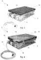
- a first device for pressurizing 1 of the heating and cooling device 2 of the device 3 for repairing conveyor belts 4 and / or connecting conveyor ends is shown.
- the device shown for pressurizing 1 has on the upper side a flat surface 5, on which further elements of the layered vulcanizing press can be arranged.
- the longer edges 6 of the plane 5 have recesses 7, in which complementary guide elements of the heating element can be used.
- On both shorter sides 8 of the device shown for pressurizing 1 mounting rods 34 can be seen, which connect the individual elements of the device for pressurizing 1.
- receiving elements 9 are not shown and draw bolt laterally beyond the upper surface 5 addition.
- the device shown for pressurizing 1 is executed plan.
- the bottom 10 is profiled or has feet.
- the transport by means of a forklift would be simplified.
- Feet, possibly also telescopic feet, could enable a stable stand even on uneven terrain.
- connecting elements would be conceivable by means of which the vulcanizing could be fixed, for example, on blocks or other storage facilities.
- Fig. 2 is a view obliquely from above of a partially mounted Vulkanisierpresse shown with a hydraulic pressure pad 11, which is arranged on the first means for pressurizing 1.
- the hydraulic pressure pad 11 has a connection 12 for supplying and removing the hydraulic fluid.
- the top and bottom of the hydraulic pressure pad 11 are formed plane-parallel so that they can be arranged as a layer in the Vulkanisierpresse.
- the width 13 of the pressure pad 11 is slightly lower than that of the device for pressurizing 1, so that a narrow edge of the upper surface 5 of the device for pressurizing 1 projects beyond the hydraulic pressure pad 11. This makes it possible that the complementary to the recesses 7 in the edges 6 of the upper surface 5 of the device for pressurizing 1 guide elements of the heating element can be guided past the hydraulic pressure pad 11 and can be inserted into the recesses 7.
- Fig. 3 shows a view obliquely from above on a partially assembled Vulkanisierpresse with a first insulating layer 14 which is disposed on the hydraulic pressure pad 11.
- the insulating layer 14 protects the heating element from damage by strong pressurization by the otherwise adjacent hydraulic pressure pad 11.
- the insulating layer 14 is preferably a layer comprising a nanoporous material. As a result, very small layer thicknesses can be achieved with very good insulation at the same time.
- a heating element 15 is positioned, in which optionally a cooling device can be integrated.
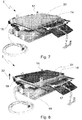
- Fig. 4 shows a view obliquely from above on a partially assembled Vulkanisierpresse with a first heating element 15, which is arranged on the first insulating layer 11.
- the heating element 15 is formed as a flat layer-like element with plane-parallel surfaces.
- On the longitudinal sides 16 of the first heating element 15 are vertically downwardly projecting guide elements 17 are arranged, which are complementary to recesses 7 in the longer edges 6 of the upper level 5 of the device for pressurizing 1 are formed.
- connection 19 is a connection for a heat transfer medium, if the required heat is brought into the interior of the vulcanizing press 3, for example by supplying an externally heated fluid.
- coolant connections may also be present, through which, in the case of the optional combination of heating and cooling element, the cooling medium can be introduced.
- Fig. 5 is a view obliquely from above of a partially mounted Vulkanisierpresse with a lower pressure plate 20, a conveyor belt 4 and wedges 21 shown, which are arranged on the first heating element
- the pressure plate 20 is advantageous to protect the heating element 15 from damage caused by any unevenness of the conveyor belt 4. Likewise, such pressure plate are used to compensate for unevenness in the parallel use of multiple heating elements 15 or vulcanizing 3 next to each other.
- it is an aluminum plate, since aluminum has very good heat-conducting properties with a comparatively low weight.
- other materials are possible here as well. For example, more flexible metals could be used, which can compensate for unevenness better than aluminum.
- the pressure plate 20 has approximately the same length 22 as the heating element 15, but is significantly wider 23 to still carry the conveyor belt 4 into a region 24 spaced from the heating element 15.
- the conveyor belt 4 and wedges 21 are positioned on the pressure plate 20, the conveyor belt 4 and wedges 21 are positioned.
- the wedges 21 have approximately the strength of the conveyor belt 4 or are slightly thinner. They are perpendicular to the pressure plate 20 on this, but are much longer 25 than the pressure plate 20 is wide. This makes it possible that the conveyor belt 4 positioned between two wedges 21 is bent downwards 26 beyond the lateral ends of the pressure plate 20, whereas the wedges 21 continue to run horizontally. This results in a clearance between the wedges 21 and above the conveyor belt 4 in which the wedges 21 with a fuse 27 can be secured against each other. As in the example shown, this can be done by chains. Likewise, however, lashing straps or the like would be possible.
- Fig. 6 shows a view obliquely from above on a partially assembled Vulkanisierpresse with an upper pressure plate 29 which is disposed above the conveyor belt 4 and the wedges 21.
- the upper pressure plate 29 serves to protect the overlying elements. Unevenness and deformation of the conveyor belt 4 or possibly on this remaining remnants of goods transported could otherwise damage the sensitive elements positioned above it at the high working pressures.
- Fig. 7 is a view obliquely from above of a partially mounted Vulkanisierpresse shown with a second heating element 30 which is arranged parallel to the first heating element 15 on the upper pressure plate 29.
- the second heating element 30 also has on one of its shorter sides 8 a projection which comprises means for connection 19 of the second heating element 30.
- this connection 19 is one with which the same energy source as for the first heating element 15 can be supplied to the second heating element 30. In the example shown, therefore, also a power connection.
- the second heating element 30 also has projecting guide elements on the longitudinal sides, which protrude perpendicularly from this. However, those of the second heating element 30 are directed vertically upwardly to stabilize the elements disposed above.
- Fig. 8 shows a view obliquely from above on a partially assembled Vulkanisierpresse with a second insulating layer 31, which is disposed on the second heating element 30.
- This second insulating layer 31 is used predominantly to avoid unnecessary heat losses of the heating element 30 in the transport belt 4 opposite direction 32. In addition, it also protects the heating element 30 against damage by a patch on this second means for pressurizing.
- This insulating layer 31 is preferably a layer comprising a nanoporous material. As shown in the picture For example, a very small layer thickness can be achieved with very good insulation at the same time.
- Fig. 9 is a view from above obliquely on a fully assembled Vulkanisierpresse with a second means 33 for pressurizing shown, which is arranged on the second insulating layer 31 and is bolted by means of tie bolts with the first means for pressurizing 1.
- the second device for pressurizing 33 also consists of several separate elements, which are connected to one another by means of mounting rods 34.
- the second pressurizing device 33 closes the vulcanizing press 3 upwards.
- the first device for pressurizing 1 it has, on the side facing the heating element 30, a flat surface on which recesses 7 are arranged along the longitudinal side, into which the complementary guide elements 17 of the heating element 30 can be inserted.
- receiving elements 9 for tension bolts 35 overlap. These have round opening 36, which extends in the direction of the respective other pressure generating device 1, 33. In these openings 36, the tension bolts 35 can be used and screwed against each other.
- the length of the adjustable by means of the draw bolt 35 distance 37 between the first 1 and second 33 pressure generating means a certain form is exerted on the arranged between the means 1, 33 for pressurizing elements of the heating and cooling device 2.
- the working pressure at which the vulcanization takes place is not adjusted via the tension bolts 35, but applied via the hydraulic pressure pad 11. So the pressure can be easily regulated and adapted to the respective needs.
- Fig. 10 shows a schematic representation of an alternative arrangement of the individual layers in a Vulkanisierpresse 3.
- the conveyor belt 4 and the above and below elements of the heating and cooling device 2 are shown.
- the analogous arrangement can also be located in opposite orientation below the conveyor belt 4. In this case, some elements can also be omitted, if they are not needed for the specific application.
- a thermally conductive cooling element 49 is arranged above the conveyor belt 4. This consists of an upper 38 and a lower 39 part. At the top 40 of the lower Partly channels 41 are formed, can be introduced into the cooling medium.
- a heating element 15 connects to the upper side.
- the materials used for the cooling element 49 must be good heat-conducting materials.
- aluminum has been found. It allows (in the absence of coolant in the channels) a good transport of heat to the conveyor belt 4.
- a particularly uniform distribution of heat over the entire support surface is ensured by this arrangement.
- possibly uneven heat application on the upper side is largely compensated during the heat transport by the cooling element 49.
- the heating element 15 is, as already shown in the previous figures, very flat elements. Preference is given to heating elements 15, 30 are used, in which the heat is generated by electrical resistances, since such elements can be made very thin.
- the heating element 15 is a device 44, which allows a thickness compensation between the heating element 15 and the above elements above.
- the material used for this layer may be the same material as used for the previously described seal 43 between the upper 38 and lower 39 parts of the cooling element 49.
- a durable material is used for this.
- This durable plastic material encases a particularly heat-insulating core 48 comprising a nanoporous material. It is not necessary that the outer jacket 47 of the Insulating layer 46 is fixedly connected to the core 48.
- the outer jacket 47 of the insulating layer 46 it is possible for the outer jacket 47 of the insulating layer 46 to form a type of trough into which the particularly heat-insulating material of the core 48 is filled and which is then closed.
- This may be advantageous, in particular in the case of a particulate airgel.
- a aerogelenthaltendes material eg a Spaceloft ® -Flies shown.
Landscapes
- Engineering & Computer Science (AREA)
- Mechanical Engineering (AREA)
- Heating, Cooling, Or Curing Plastics Or The Like In General (AREA)
- Belt Conveyors (AREA)
Claims (11)
- Dispositif (3) de réparation de bandes de convoyage (4) et/ou de liaison d'extrémités de bandes de convoyage par vulcanisation sous haute pression avec un dispositif de chauffage et de refroidissement (2), qui peut être exposé à une haute pression à l'aide d'éléments d'application de pression, le dispositif de chauffage et de refroidissement (2) étant constitué de plusieurs couches et la bande de convoyage (4) ou les extrémités de la bande de convoyage pouvant être disposée(s) dans le sens de la largeur parallèlement aux couches et le dispositif de chauffage et de refroidissement (2) comprenant, au moins sur un côté de la bande de convoyage (4) à vulcaniser et/ou des extrémités de la bande de convoyage à vulcaniser, au moins une couche thermo-conductrice avec un élément de refroidissement (49) et un élément chauffant (15), caractérisé en ce que le dispositif de chauffage et de refroidissement (2) comprend, au moins sur un côté de la bande de convoyage (4) à vulcaniser et/ou des extrémités de la bande de convoyage à vulcaniser, au moins une couche isolante nano-poreuse (46), le dispositif de chauffage et de refroidissement (2) à structure en couches comprend en outre une couche isolante dont le revêtement externe (47) comprend un matériau résistant et qui entoure un noyau (48) thermo-isolant de la couche isolante nano-poreuse (46), la couche isolante (46) comprenant un aérogel sous forme de particules.
- Dispositif (3) de réparation de bandes de convoyage (4) et/ou de liaison d'extrémités de bandes de convoyage selon la revendication 1, caractérisé en ce que la couche isolante nano-poreuse (46) comprend un matériau contenant un aérogel.
- Dispositif (3) de réparation de bandes de convoyage (4) et/ou de liaison d'extrémités de bandes de convoyage selon la revendication 2, caractérisé en ce que la couche isolante nano-poreuse (46) comprend un non-tissé contenant un aérogel.
- Dispositif (3) de réparation de bandes de convoyage (4) et/ou de liaison d'extrémités de bandes de convoyage selon l'une des revendications précédentes, caractérisé en ce que la couche isolante (47) comprend une matière plastique résistante à la chaleur.
- Dispositif (3) de réparation de bandes de convoyage (4) et/ou de liaison d'extrémités de bandes de convoyage selon l'une des revendications précédentes, caractérisé en ce que la couche thermo-conductrice est constituée d'un métal thermo-conducteur et comprend des canaux (41) et des branchements (12) pour un refroidissement par eau.
- Dispositif (3) de réparation de bandes de convoyage (4) et/ou de liaison d'extrémités de bandes de convoyage selon l'une des revendications précédentes, caractérisé en ce que le dispositif de chauffage et de refroidissement (2) présente, sur le côté de la bande de convoyage (4) à vulcaniser et/ou des extrémités des bandes de convoyage à vulcaniser, qui comprend l'élément de refroidissement (49), un joint d'étanchéité (43), l'élément chauffant (15) et la couche isolante nano-poreuse (46), une épaisseur inférieure à 50 mm, de préférence inférieure à 30 mm, plus particulièrement de préférence inférieure à 25 mm.
- Dispositif (3) de réparation de bandes de convoyage (4) et/ou de liaison d'extrémités de bandes de convoyage selon les revendications 5 ou 6, caractérisé en ce qu' un joint d'étanchéité (43) constitué d'un élastomère fluoré thermiquement résistant est disposé à proximité des canaux (41).
- Dispositif (3) de réparation de bandes de convoyage (4) et/ou de liaison d'extrémités de bandes de convoyage selon l'une des revendications précédentes, caractérisé en ce que le dispositif de chauffage et de refroidissement (2) peut être exposé à des pressions > 10 bar, de préférence > 15 bar, plus particulièrement de préférence > 20 bar.
- Dispositif (3) de réparation de bandes de convoyage (4) et/ou de liaison d'extrémités de bandes de convoyage selon l'une des revendications précédentes, caractérisé en ce que le dispositif de chauffage et de refroidissement (2) peut être chauffé au niveau d'un point de contact avec la bande de convoyage (4) et/ou les extrémités des bandes de convoyage à une température > 150°C, de préférence > 180°C, plus particulièrement de préférence > 200°C.
- Dispositif (3) de réparation de bandes de convoyage (4) et/ou de liaison d'extrémités de bandes de convoyage selon l'une des revendications précédentes, caractérisé en ce que le dispositif (3) est adapté, au moins, à la réparation et/ou à la liaison de sangles textiles monocouches, de sangles textiles multicouches et/ou de sangles en câbles d'acier.
- Procédé de réparation de bandes de convoyage (4) et/ou de liaison d'extrémités de bandes de convoyage à l'aide d'un dispositif (3) selon l'une des revendications précédentes, un dispositif de chauffage et de refroidissement (2) constitué de plusieurs couches étant disposé parallèlement à la bande de convoyage (4) et/ou aux extrémités des bandes de convoyage, caractérisé en ce que le dispositif de chauffage et de refroidissement (2) comprend une couche isolante nano-poreuse (46) avec un noyau (48) thermo-isolant et une couche isolante entourant celui-ci, dont le revêtement externe (47) contient un matériau résistant, la couche isolante (46) contenant un aérogel sous forme de particules.
Applications Claiming Priority (1)
| Application Number | Priority Date | Filing Date | Title |
|---|---|---|---|
| DE102010036104.6A DE102010036104B4 (de) | 2010-09-01 | 2010-09-01 | Heizelement für eine Vulkanisierpresse mit nanoporöser Isolierschicht |
Publications (2)
| Publication Number | Publication Date |
|---|---|
| EP2425962A1 EP2425962A1 (fr) | 2012-03-07 |
| EP2425962B1 true EP2425962B1 (fr) | 2014-04-30 |
Family
ID=44533952
Family Applications (1)
| Application Number | Title | Priority Date | Filing Date |
|---|---|---|---|
| EP20110177699 Not-in-force EP2425962B1 (fr) | 2010-09-01 | 2011-08-16 | Elément de chauffage pour une presse de vulcanisation dotée d'une couche isolante nanoporeuse et procédé utilisant ledit élément |
Country Status (3)
| Country | Link |
|---|---|
| EP (1) | EP2425962B1 (fr) |
| DE (1) | DE102010036104B4 (fr) |
| ES (1) | ES2475143T3 (fr) |
Families Citing this family (3)
| Publication number | Priority date | Publication date | Assignee | Title |
|---|---|---|---|---|
| DE102013226083A1 (de) * | 2013-12-16 | 2015-06-18 | Contitech Ag | Druckfestes Isolierelement für beheizbare Pressen |
| GB201516626D0 (en) * | 2015-09-18 | 2015-11-04 | Shaw Almex Ind Ltd | Modular belt splicer |
| CN112238631B (zh) * | 2020-10-12 | 2021-06-08 | 梁山水泊胶带股份有限公司 | 一种橡胶输送带纵向裂纹的检修装置 |
Family Cites Families (6)
| Publication number | Priority date | Publication date | Assignee | Title |
|---|---|---|---|---|
| NL111172C (fr) * | ||||
| DE1729858B1 (de) * | 1967-11-22 | 1972-08-03 | Wagener & Co | Transportable Vulkanisierpresse |
| US3969051A (en) * | 1975-06-13 | 1976-07-13 | D.G. Rung Industries, Inc. | Vulcanizing apparatus |
| DE2848733A1 (de) * | 1978-11-10 | 1980-05-22 | Becker & Van Huellen | Plattenpresse |
| DE202004017115U1 (de) * | 2004-11-05 | 2006-03-16 | SCHWENK DÄMMTECHNIK GMBH & Co KG | Wärmedämmplatte |
| DE102007002594B4 (de) * | 2007-01-12 | 2012-08-30 | Bayerisches Zentrum für Angewandte Energieforschung e.V. | Formkörper aus hochporösem kohlenstoffhaltigen Aerogel und Verfahren zu deren Herstellung |
-
2010
- 2010-09-01 DE DE102010036104.6A patent/DE102010036104B4/de not_active Expired - Fee Related
-
2011
- 2011-08-16 ES ES11177699.3T patent/ES2475143T3/es active Active
- 2011-08-16 EP EP20110177699 patent/EP2425962B1/fr not_active Not-in-force
Also Published As
| Publication number | Publication date |
|---|---|
| EP2425962A1 (fr) | 2012-03-07 |
| ES2475143T3 (es) | 2014-07-10 |
| DE102010036104B4 (de) | 2017-11-23 |
| DE102010036104A1 (de) | 2012-03-01 |
Similar Documents
| Publication | Publication Date | Title |
|---|---|---|
| EP2425962B1 (fr) | Elément de chauffage pour une presse de vulcanisation dotée d'une couche isolante nanoporeuse et procédé utilisant ledit élément | |
| DE102013224204A1 (de) | Anlage zur Herstellung von Holzpellets oder anderen festen Granulaten aus kleinstückigem Material organischen/pflanzlichen Ursprungs | |
| AT501192B1 (de) | Vorrichtung zum transportieren und stützen tafelförmiger gegenstände, insbesondere glastafeln | |
| DE3028145C2 (fr) | ||
| EP2179220B1 (fr) | Plaque de grill à refroidissement par un liquide, présentant des plaques d'usure, et grill à gradins formé de telles plaques de grill | |
| EP2044378A1 (fr) | Dispositif de refroidissement d'un produit en vrac | |
| DE202010012086U1 (de) | Vulkanisierpresse mit Heizelement mit Polyimidschicht | |
| DD236945A5 (de) | Vorrichtung zur gewinnung der fuehlbaren waerme von schuettfaehigem heissgut | |
| DE102009023577A1 (de) | Presse, insbesondere kontinuierlich arbeitende Presse zur Herstellung von Werkstoffplatten | |
| WO2013045060A1 (fr) | Dispositif de fixation pour boîtier d'extrudeuse | |
| EP4522901B1 (fr) | Système de distribution du liquide de refroidissement d'une batterie | |
| DE2728993C2 (de) | Stranggießkokille | |
| EP3573878A1 (fr) | Ensemble auto-porteur pour véhicule | |
| DE4208263A1 (de) | Kontinuierliche presse fuer das pressen einer pressgutmatte im zuge der herstellung von spanplatten, faserplatten u. dgl. | |
| DE4400347C5 (de) | Kontinuierlich arbeitende Presse | |
| US4417865A (en) | Continuously operating press | |
| DE3725007A1 (de) | Viel-platten-presse zum herstellen von laminaten unter unterdruck | |
| DE29701263U1 (de) | Vorrichtung zur Verarbeitung von Teilen und Kühlstation für diese Vorrichtung | |
| EP0512300B1 (fr) | Presse, notamment presse de placage | |
| EP2361748A1 (fr) | Dispositif amélioré pour la production de longs profils en plastique par extrusion | |
| DE10234235B4 (de) | Etagenpresse | |
| DE2739687C2 (fr) | ||
| DE20100627U1 (de) | Heizpresse | |
| DE202017103053U1 (de) | Vorpresse und System zum kontinuierlichen Herstellen von Werkstoffplatten und Transportvorrichtung zum Aufnehmen des Pressenbandes | |
| DE4334161C2 (de) | Vorrichtung zur Herstellung von plattenartigen Formteilen aus Kunststoff |
Legal Events
| Date | Code | Title | Description |
|---|---|---|---|
| AK | Designated contracting states |
Kind code of ref document: A1 Designated state(s): AL AT BE BG CH CY CZ DE DK EE ES FI FR GB GR HR HU IE IS IT LI LT LU LV MC MK MT NL NO PL PT RO RS SE SI SK SM TR |
|
| AX | Request for extension of the european patent |
Extension state: BA ME |
|
| PUAI | Public reference made under article 153(3) epc to a published international application that has entered the european phase |
Free format text: ORIGINAL CODE: 0009012 |
|
| 17P | Request for examination filed |
Effective date: 20120820 |
|
| 17Q | First examination report despatched |
Effective date: 20130717 |
|
| REG | Reference to a national code |
Ref country code: DE Ref legal event code: R079 Ref document number: 502011002884 Country of ref document: DE Free format text: PREVIOUS MAIN CLASS: B29D0029060000 Ipc: B29C0035160000 |
|
| GRAP | Despatch of communication of intention to grant a patent |
Free format text: ORIGINAL CODE: EPIDOSNIGR1 |
|
| RIC1 | Information provided on ipc code assigned before grant |
Ipc: H05B 3/12 20060101ALI20131202BHEP Ipc: B29C 73/30 20060101ALI20131202BHEP Ipc: B29C 35/02 20060101ALN20131202BHEP Ipc: B29C 35/16 20060101AFI20131202BHEP Ipc: B30B 15/06 20060101ALI20131202BHEP |
|
| INTG | Intention to grant announced |
Effective date: 20140108 |
|
| RIC1 | Information provided on ipc code assigned before grant |
Ipc: B29C 35/02 20060101ALN20131218BHEP Ipc: B29C 35/16 20060101AFI20131218BHEP Ipc: H05B 3/12 20060101ALI20131218BHEP Ipc: B29C 73/30 20060101ALI20131218BHEP Ipc: B30B 15/06 20060101ALI20131218BHEP |
|
| GRAS | Grant fee paid |
Free format text: ORIGINAL CODE: EPIDOSNIGR3 |
|
| GRAA | (expected) grant |
Free format text: ORIGINAL CODE: 0009210 |
|
| AK | Designated contracting states |
Kind code of ref document: B1 Designated state(s): AL AT BE BG CH CY CZ DE DK EE ES FI FR GB GR HR HU IE IS IT LI LT LU LV MC MK MT NL NO PL PT RO RS SE SI SK SM TR |
|
| REG | Reference to a national code |
Ref country code: GB Ref legal event code: FG4D Free format text: NOT ENGLISH Ref country code: CH Ref legal event code: EP |
|
| REG | Reference to a national code |
Ref country code: AT Ref legal event code: REF Ref document number: 664798 Country of ref document: AT Kind code of ref document: T Effective date: 20140515 |
|
| REG | Reference to a national code |
Ref country code: IE Ref legal event code: FG4D Free format text: LANGUAGE OF EP DOCUMENT: GERMAN |
|
| REG | Reference to a national code |
Ref country code: DE Ref legal event code: R096 Ref document number: 502011002884 Country of ref document: DE Effective date: 20140618 |
|
| REG | Reference to a national code |
Ref country code: ES Ref legal event code: FG2A Ref document number: 2475143 Country of ref document: ES Kind code of ref document: T3 Effective date: 20140710 |
|
| REG | Reference to a national code |
Ref country code: LT Ref legal event code: MG4D |
|
| REG | Reference to a national code |
Ref country code: NL Ref legal event code: VDEP Effective date: 20140430 |
|
| PG25 | Lapsed in a contracting state [announced via postgrant information from national office to epo] |
Ref country code: NL Free format text: LAPSE BECAUSE OF FAILURE TO SUBMIT A TRANSLATION OF THE DESCRIPTION OR TO PAY THE FEE WITHIN THE PRESCRIBED TIME-LIMIT Effective date: 20140430 Ref country code: CY Free format text: LAPSE BECAUSE OF FAILURE TO SUBMIT A TRANSLATION OF THE DESCRIPTION OR TO PAY THE FEE WITHIN THE PRESCRIBED TIME-LIMIT Effective date: 20140430 Ref country code: IS Free format text: LAPSE BECAUSE OF FAILURE TO SUBMIT A TRANSLATION OF THE DESCRIPTION OR TO PAY THE FEE WITHIN THE PRESCRIBED TIME-LIMIT Effective date: 20140830 Ref country code: GR Free format text: LAPSE BECAUSE OF FAILURE TO SUBMIT A TRANSLATION OF THE DESCRIPTION OR TO PAY THE FEE WITHIN THE PRESCRIBED TIME-LIMIT Effective date: 20140731 Ref country code: LT Free format text: LAPSE BECAUSE OF FAILURE TO SUBMIT A TRANSLATION OF THE DESCRIPTION OR TO PAY THE FEE WITHIN THE PRESCRIBED TIME-LIMIT Effective date: 20140430 Ref country code: BG Free format text: LAPSE BECAUSE OF FAILURE TO SUBMIT A TRANSLATION OF THE DESCRIPTION OR TO PAY THE FEE WITHIN THE PRESCRIBED TIME-LIMIT Effective date: 20140730 Ref country code: NO Free format text: LAPSE BECAUSE OF FAILURE TO SUBMIT A TRANSLATION OF THE DESCRIPTION OR TO PAY THE FEE WITHIN THE PRESCRIBED TIME-LIMIT Effective date: 20140730 Ref country code: FI Free format text: LAPSE BECAUSE OF FAILURE TO SUBMIT A TRANSLATION OF THE DESCRIPTION OR TO PAY THE FEE WITHIN THE PRESCRIBED TIME-LIMIT Effective date: 20140430 |
|
| PG25 | Lapsed in a contracting state [announced via postgrant information from national office to epo] |
Ref country code: RS Free format text: LAPSE BECAUSE OF FAILURE TO SUBMIT A TRANSLATION OF THE DESCRIPTION OR TO PAY THE FEE WITHIN THE PRESCRIBED TIME-LIMIT Effective date: 20140430 Ref country code: HR Free format text: LAPSE BECAUSE OF FAILURE TO SUBMIT A TRANSLATION OF THE DESCRIPTION OR TO PAY THE FEE WITHIN THE PRESCRIBED TIME-LIMIT Effective date: 20140430 Ref country code: PL Free format text: LAPSE BECAUSE OF FAILURE TO SUBMIT A TRANSLATION OF THE DESCRIPTION OR TO PAY THE FEE WITHIN THE PRESCRIBED TIME-LIMIT Effective date: 20140430 Ref country code: SE Free format text: LAPSE BECAUSE OF FAILURE TO SUBMIT A TRANSLATION OF THE DESCRIPTION OR TO PAY THE FEE WITHIN THE PRESCRIBED TIME-LIMIT Effective date: 20140430 Ref country code: LV Free format text: LAPSE BECAUSE OF FAILURE TO SUBMIT A TRANSLATION OF THE DESCRIPTION OR TO PAY THE FEE WITHIN THE PRESCRIBED TIME-LIMIT Effective date: 20140430 |
|
| PG25 | Lapsed in a contracting state [announced via postgrant information from national office to epo] |
Ref country code: PT Free format text: LAPSE BECAUSE OF FAILURE TO SUBMIT A TRANSLATION OF THE DESCRIPTION OR TO PAY THE FEE WITHIN THE PRESCRIBED TIME-LIMIT Effective date: 20140901 |
|
| PG25 | Lapsed in a contracting state [announced via postgrant information from national office to epo] |
Ref country code: RO Free format text: LAPSE BECAUSE OF FAILURE TO SUBMIT A TRANSLATION OF THE DESCRIPTION OR TO PAY THE FEE WITHIN THE PRESCRIBED TIME-LIMIT Effective date: 20140430 Ref country code: DK Free format text: LAPSE BECAUSE OF FAILURE TO SUBMIT A TRANSLATION OF THE DESCRIPTION OR TO PAY THE FEE WITHIN THE PRESCRIBED TIME-LIMIT Effective date: 20140430 Ref country code: EE Free format text: LAPSE BECAUSE OF FAILURE TO SUBMIT A TRANSLATION OF THE DESCRIPTION OR TO PAY THE FEE WITHIN THE PRESCRIBED TIME-LIMIT Effective date: 20140430 Ref country code: SK Free format text: LAPSE BECAUSE OF FAILURE TO SUBMIT A TRANSLATION OF THE DESCRIPTION OR TO PAY THE FEE WITHIN THE PRESCRIBED TIME-LIMIT Effective date: 20140430 Ref country code: CZ Free format text: LAPSE BECAUSE OF FAILURE TO SUBMIT A TRANSLATION OF THE DESCRIPTION OR TO PAY THE FEE WITHIN THE PRESCRIBED TIME-LIMIT Effective date: 20140430 |
|
| REG | Reference to a national code |
Ref country code: DE Ref legal event code: R097 Ref document number: 502011002884 Country of ref document: DE |
|
| PLBE | No opposition filed within time limit |
Free format text: ORIGINAL CODE: 0009261 |
|
| STAA | Information on the status of an ep patent application or granted ep patent |
Free format text: STATUS: NO OPPOSITION FILED WITHIN TIME LIMIT |
|
| PG25 | Lapsed in a contracting state [announced via postgrant information from national office to epo] |
Ref country code: IT Free format text: LAPSE BECAUSE OF FAILURE TO SUBMIT A TRANSLATION OF THE DESCRIPTION OR TO PAY THE FEE WITHIN THE PRESCRIBED TIME-LIMIT Effective date: 20140430 Ref country code: MC Free format text: LAPSE BECAUSE OF FAILURE TO SUBMIT A TRANSLATION OF THE DESCRIPTION OR TO PAY THE FEE WITHIN THE PRESCRIBED TIME-LIMIT Effective date: 20140430 Ref country code: LU Free format text: LAPSE BECAUSE OF FAILURE TO SUBMIT A TRANSLATION OF THE DESCRIPTION OR TO PAY THE FEE WITHIN THE PRESCRIBED TIME-LIMIT Effective date: 20140816 |
|
| REG | Reference to a national code |
Ref country code: CH Ref legal event code: PL |
|
| 26N | No opposition filed |
Effective date: 20150202 |
|
| PG25 | Lapsed in a contracting state [announced via postgrant information from national office to epo] |
Ref country code: LI Free format text: LAPSE BECAUSE OF NON-PAYMENT OF DUE FEES Effective date: 20140831 Ref country code: BE Free format text: LAPSE BECAUSE OF NON-PAYMENT OF DUE FEES Effective date: 20140831 Ref country code: CH Free format text: LAPSE BECAUSE OF NON-PAYMENT OF DUE FEES Effective date: 20140831 |
|
| REG | Reference to a national code |
Ref country code: DE Ref legal event code: R097 Ref document number: 502011002884 Country of ref document: DE Effective date: 20150202 |
|
| REG | Reference to a national code |
Ref country code: IE Ref legal event code: MM4A |
|
| PG25 | Lapsed in a contracting state [announced via postgrant information from national office to epo] |
Ref country code: SI Free format text: LAPSE BECAUSE OF FAILURE TO SUBMIT A TRANSLATION OF THE DESCRIPTION OR TO PAY THE FEE WITHIN THE PRESCRIBED TIME-LIMIT Effective date: 20140430 |
|
| PG25 | Lapsed in a contracting state [announced via postgrant information from national office to epo] |
Ref country code: IE Free format text: LAPSE BECAUSE OF NON-PAYMENT OF DUE FEES Effective date: 20140816 |
|
| GBPC | Gb: european patent ceased through non-payment of renewal fee |
Effective date: 20150816 |
|
| PG25 | Lapsed in a contracting state [announced via postgrant information from national office to epo] |
Ref country code: SM Free format text: LAPSE BECAUSE OF FAILURE TO SUBMIT A TRANSLATION OF THE DESCRIPTION OR TO PAY THE FEE WITHIN THE PRESCRIBED TIME-LIMIT Effective date: 20140430 |
|
| PG25 | Lapsed in a contracting state [announced via postgrant information from national office to epo] |
Ref country code: MT Free format text: LAPSE BECAUSE OF FAILURE TO SUBMIT A TRANSLATION OF THE DESCRIPTION OR TO PAY THE FEE WITHIN THE PRESCRIBED TIME-LIMIT Effective date: 20140430 |
|
| PG25 | Lapsed in a contracting state [announced via postgrant information from national office to epo] |
Ref country code: HU Free format text: LAPSE BECAUSE OF FAILURE TO SUBMIT A TRANSLATION OF THE DESCRIPTION OR TO PAY THE FEE WITHIN THE PRESCRIBED TIME-LIMIT; INVALID AB INITIO Effective date: 20110816 Ref country code: TR Free format text: LAPSE BECAUSE OF FAILURE TO SUBMIT A TRANSLATION OF THE DESCRIPTION OR TO PAY THE FEE WITHIN THE PRESCRIBED TIME-LIMIT Effective date: 20140430 Ref country code: GB Free format text: LAPSE BECAUSE OF NON-PAYMENT OF DUE FEES Effective date: 20150816 |
|
| REG | Reference to a national code |
Ref country code: FR Ref legal event code: PLFP Year of fee payment: 6 |
|
| REG | Reference to a national code |
Ref country code: FR Ref legal event code: PLFP Year of fee payment: 7 |
|
| REG | Reference to a national code |
Ref country code: AT Ref legal event code: MM01 Ref document number: 664798 Country of ref document: AT Kind code of ref document: T Effective date: 20160816 |
|
| PG25 | Lapsed in a contracting state [announced via postgrant information from national office to epo] |
Ref country code: AT Free format text: LAPSE BECAUSE OF NON-PAYMENT OF DUE FEES Effective date: 20160816 |
|
| PGFP | Annual fee paid to national office [announced via postgrant information from national office to epo] |
Ref country code: DE Payment date: 20170807 Year of fee payment: 7 Ref country code: FR Payment date: 20170823 Year of fee payment: 7 Ref country code: ES Payment date: 20170901 Year of fee payment: 7 |
|
| PG25 | Lapsed in a contracting state [announced via postgrant information from national office to epo] |
Ref country code: MK Free format text: LAPSE BECAUSE OF FAILURE TO SUBMIT A TRANSLATION OF THE DESCRIPTION OR TO PAY THE FEE WITHIN THE PRESCRIBED TIME-LIMIT Effective date: 20140430 |
|
| PG25 | Lapsed in a contracting state [announced via postgrant information from national office to epo] |
Ref country code: AL Free format text: LAPSE BECAUSE OF FAILURE TO SUBMIT A TRANSLATION OF THE DESCRIPTION OR TO PAY THE FEE WITHIN THE PRESCRIBED TIME-LIMIT Effective date: 20140430 |
|
| REG | Reference to a national code |
Ref country code: DE Ref legal event code: R119 Ref document number: 502011002884 Country of ref document: DE |
|
| PG25 | Lapsed in a contracting state [announced via postgrant information from national office to epo] |
Ref country code: DE Free format text: LAPSE BECAUSE OF NON-PAYMENT OF DUE FEES Effective date: 20190301 |
|
| PG25 | Lapsed in a contracting state [announced via postgrant information from national office to epo] |
Ref country code: FR Free format text: LAPSE BECAUSE OF NON-PAYMENT OF DUE FEES Effective date: 20180831 |
|
| REG | Reference to a national code |
Ref country code: ES Ref legal event code: FD2A Effective date: 20190918 |
|
| PG25 | Lapsed in a contracting state [announced via postgrant information from national office to epo] |
Ref country code: ES Free format text: LAPSE BECAUSE OF NON-PAYMENT OF DUE FEES Effective date: 20180817 |