EP2425757A2 - Staubsammler mit nasstrennung für einen staubsauger - Google Patents
Staubsammler mit nasstrennung für einen staubsauger Download PDFInfo
- Publication number
- EP2425757A2 EP2425757A2 EP10769867A EP10769867A EP2425757A2 EP 2425757 A2 EP2425757 A2 EP 2425757A2 EP 10769867 A EP10769867 A EP 10769867A EP 10769867 A EP10769867 A EP 10769867A EP 2425757 A2 EP2425757 A2 EP 2425757A2
- Authority
- EP
- European Patent Office
- Prior art keywords
- dust
- dust collector
- unit
- water
- water storage
- Prior art date
- Legal status (The legal status is an assumption and is not a legal conclusion. Google has not performed a legal analysis and makes no representation as to the accuracy of the status listed.)
- Withdrawn
Links
Images


Classifications
-
- A—HUMAN NECESSITIES
- A47—FURNITURE; DOMESTIC ARTICLES OR APPLIANCES; COFFEE MILLS; SPICE MILLS; SUCTION CLEANERS IN GENERAL
- A47L—DOMESTIC WASHING OR CLEANING; SUCTION CLEANERS IN GENERAL
- A47L9/00—Details or accessories of suction cleaners, e.g. mechanical means for controlling the suction or for effecting pulsating action; Storing devices specially adapted to suction cleaners or parts thereof; Carrying-vehicles specially adapted for suction cleaners
- A47L9/10—Filters; Dust separators; Dust removal; Automatic exchange of filters
- A47L9/16—Arrangement or disposition of cyclones or other devices with centrifugal action
- A47L9/1608—Cyclonic chamber constructions
-
- A—HUMAN NECESSITIES
- A47—FURNITURE; DOMESTIC ARTICLES OR APPLIANCES; COFFEE MILLS; SPICE MILLS; SUCTION CLEANERS IN GENERAL
- A47L—DOMESTIC WASHING OR CLEANING; SUCTION CLEANERS IN GENERAL
- A47L9/00—Details or accessories of suction cleaners, e.g. mechanical means for controlling the suction or for effecting pulsating action; Storing devices specially adapted to suction cleaners or parts thereof; Carrying-vehicles specially adapted for suction cleaners
- A47L9/10—Filters; Dust separators; Dust removal; Automatic exchange of filters
- A47L9/16—Arrangement or disposition of cyclones or other devices with centrifugal action
- A47L9/1683—Dust collecting chambers; Dust collecting receptacles
-
- A—HUMAN NECESSITIES
- A47—FURNITURE; DOMESTIC ARTICLES OR APPLIANCES; COFFEE MILLS; SPICE MILLS; SUCTION CLEANERS IN GENERAL
- A47L—DOMESTIC WASHING OR CLEANING; SUCTION CLEANERS IN GENERAL
- A47L9/00—Details or accessories of suction cleaners, e.g. mechanical means for controlling the suction or for effecting pulsating action; Storing devices specially adapted to suction cleaners or parts thereof; Carrying-vehicles specially adapted for suction cleaners
- A47L9/10—Filters; Dust separators; Dust removal; Automatic exchange of filters
- A47L9/18—Liquid filters
- A47L9/183—Spray cleaning
-
- B—PERFORMING OPERATIONS; TRANSPORTING
- B04—CENTRIFUGAL APPARATUS OR MACHINES FOR CARRYING-OUT PHYSICAL OR CHEMICAL PROCESSES
- B04C—APPARATUS USING FREE VORTEX FLOW, e.g. CYCLONES
- B04C5/00—Apparatus in which the axial direction of the vortex is reversed
- B04C5/14—Construction of the underflow ducting; Apex constructions; Discharge arrangements ; discharge through sidewall provided with a few slits or perforations
- B04C5/185—Dust collectors
-
- B—PERFORMING OPERATIONS; TRANSPORTING
- B04—CENTRIFUGAL APPARATUS OR MACHINES FOR CARRYING-OUT PHYSICAL OR CHEMICAL PROCESSES
- B04C—APPARATUS USING FREE VORTEX FLOW, e.g. CYCLONES
- B04C9/00—Combinations with other devices, e.g. fans, expansion chambers, diffusors, water locks
- B04C2009/008—Combinations with other devices, e.g. fans, expansion chambers, diffusors, water locks with injection or suction of gas or liquid into the cyclone
Definitions
- the present invention relates to a dust collector for a vacuum cleaner, and more particularly to a wet separation type dust collector to create liquid droplets so as to separate fine dust particles in a vacuum cleaner for domestic, industrial, business use, and the like.
- a dust collector for a centrifuging type vacuum cleaner which is known as a cyclone cleaner includes a centrifuge to rotate air containing dust so as to separate dust particles by centrifugal force, and a dust container to collect the separated dust particles.
- centrifuging type vacuum cleaner does not need a separate dust bag for collection of dust. Also, the centrifuging type vacuum cleaner causes no problem in that air permeability is deteriorated due to foreign matter which is caught in the dust bag unlike vacuum cleaners to separate dust particles using the dust bag, thereby not causing deterioration in cleaning efficiency.
- the centrifuging type vacuum cleaner separates dust particles by centrifugal force, there is a problem in that light-weight and small fine dust particles may not be separated from air introduced into the dust collector by centrifugal force.
- the fine dust particles which are not separated block a prefilter or an exhaust filter, thereby resulting in deterioration in air permeability. Consequently, a problem which frequently repairs the prefilter or the exhaust filter may be generated.
- the related art discloses vacuum cleaners which perform cleaning using water, for example, a steam spraying mode, a wet dust separation mode, or the like.
- Examples of the above-mentioned related art include Korean Patent No. 10-813537 entitled “steam vacuum cleaner” (hereinafter, referred to as 'related art 1') and Korean patent Laid-open publication No. 10-2007-19920 entitled “vacuum cleaner” (hereinafter, referred to as 'related art 2').
- Related art 1 discloses a steam vacuum cleaner which performs cleaning in such a manner that steam is created by heating water stored in a water tank pump with a heater and is then sprayed onto a cleaning surface.
- the steam allows bacteria, microorganisms, etc. of the cleaning surface to be sterilized, and water created by liquefaction of the steam enables cohesion of dust and the like. As a result, cleaning efficiency of the cleaning surface may be improved.
- related art 2 discloses a vacuum cleaner which may easily separate fine dust particles in such a manner that the dust collector is provided at a base portion thereof with a liquid droplet generating unit and a liquid droplet injection unit so as to spray liquid droplets into the dust collector.
- related art 2 since related art 2 has a configuration which locally generates liquid droplets, generation efficiency of the liquid droplets may be deteriorated. Consequently, there is a problem which deteriorates fine dust separation efficiency by the liquid droplets.
- the present invention has been made in view of the above problems, and it is an object of the present invention to provide a wet separation type dust collector for a vacuum cleaner capable of automatically spraying liquid droplets without a separate spraying means and improving dust separation efficiency within a dust separation unit.
- a wet separation type dust collector for a vacuum cleaner including a dust collecting unit to collect dust particles discharged from a centrifuging unit, and a water storage unit to store water, wherein the dust collecting unit is formed at a side wall thereof with a plurality of liquid droplet spray holes so that liquid droplets are automatically sprayed into the dust collecting unit by vacuum pressure of the vacuum cleaner.
- Each of the plural liquid droplet spray holes may be formed to have a different diameter in order to create liquid droplets having various sizes so that the liquid droplets may be bound with fine dust particles having various sizes.
- the liquid droplet spray hole should have a size at which generation of liquid droplets is not prevented due to surface tension of water.
- the liquid droplet spray hole may have a diameter of 0.3 mm to 10 mm so that generation of liquid droplets is not prevented due to surface tension of water, and may preferably have a diameter of 3 mm to 5 mm in order to more stably generate liquid droplets.
- the water storage unit may have a smaller volume than the volume of the dust collecting unit in order to prevent water collected in the dust collecting unit from overflowing.
- the water storage unit may be coupled to an outer side surface of the dust collecting unit so as to form a water storage region at an outer side of the dust collecting unit.
- the water storage unit may further include a handle portion to mount the dust collector to the vacuum cleaner or to separate the dust collector from the vacuum cleaner.
- the handle portion may have a water inlet opened at an upper portion thereof and be formed at a base portion thereof with a through hole to communicate with the water storage region of the water storage unit.
- the dust collector of the present invention may further include water supply portions located within the water storage unit while being respectively formed at positions of the liquid droplet spray holes.
- Each of the water supply portions may be formed at a base portion thereof so as to be submerged under the water stored in the water storage unit, and may have an inner diameter greater than the diameter of each liquid droplet spray hole.
- Each of the water supply portions may be vertically provided at an outer peripheral surface of the side wall of the dust collecting unit.
- the inner diameter of the water supply portion may be formed so that rise of water is decreased by vacuum pressure of the vacuum cleaner.
- the present invention has an effect of easily separating fine dust particles which are not separated from a centrifuging unit by spraying liquid droplets having various sizes within a dust collecting unit.
- the present invention has an effect of allowing liquid droplets to be evenly distributed throughout upper portions of the dust collecting unit and the centrifuging unit by forming a plurality of liquid droplet spray holes along an upper wall of the dust collecting unit so as to spray liquid droplets, thereby improving separation efficiency of fine dust particles.
- the present invention has an effect of rapidly moving fine dust particles, which float within the dust collecting unit, towards a base portion of the dust collecting unit, in order to prevent the floating fine dust particles from flowing backwards.
- the present invention has an effect of easily raising water stored in a water storage unit up to the liquid droplet spray holes by provision of water supply portions, thereby improving generation efficiency of liquid droplets.
- FIG. 1 is a perspective view illustrating a dust collector 1 for a vacuum cleaner according to an embodiment of the present invention.
- FIG. 2 is an exploded perspective view illustrating the dust collector 1 of FIG. 1 .
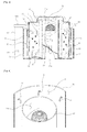
- FIG. 3 is a sectional view illustrating the dust collector 1 of FIG. 1 .
- FIG. 4 is a partially cut away perspective view of the dust collector 1 illustrating arrangement of liquid droplet spray holes 32.
- the dust collector 1 shown in FIGS. 1 to 3 includes a cover 10, a centrifuging unit 20, a dust collecting unit 30, water supply portions 40, and a water storage unit 50.
- the centrifuging unit 20 is coupled to an inner side of the dust collecting unit 30
- the water storage unit 50 is coupled to an outer side of the dust collecting unit 30
- the water supply portions 40 are coupled to an outer side surface of the dust collecting unit 30 within the water storage unit 50.
- the centrifuging unit 20 is formed with an inlet 25. Also, the centrifuging unit 20 includes a centrifuging tube 21 by which a centrifuging region 21a is defined at an inner side of the centrifuging unit 20, an exhaust tube 23 formed at an inner side of the centrifuging tube 21, and a passage guide 24 formed at an outer side of the exhaust tube 23 in a spiral fashion in order to guide outdoor air introduced through the inlet 25 so that the outdoor air rotates along an outer peripheral surface of the exhaust tube 23 and moves upwards.
- a centrifuging tube 21 by which a centrifuging region 21a is defined at an inner side of the centrifuging unit 20, an exhaust tube 23 formed at an inner side of the centrifuging tube 21, and a passage guide 24 formed at an outer side of the exhaust tube 23 in a spiral fashion in order to guide outdoor air introduced through the inlet 25 so that the outdoor air rotates along an outer peripheral surface of the exhaust tube 23 and moves upwards.
- the exhaust tube 23 is opened at an upper portion thereof with a grill 22 while being formed, at a base portion thereof, as a cylinder tube composed of an exhaust hole 23a through which air is discharged.
- the dust collecting unit 30 is sealed at an upper portion thereof by the cover 10 which is able to be opened and closed. Also, the dust collecting unit 30 is coupled at the inner side thereof with the centrifuging unit 20 and is formed as a container in which an outer side region of the centrifuging unit 20 is defined as a dust collecting region 31 to collect dust particles 3 separated by the centrifuging unit 20.
- the dust collecting unit 30 is formed at an upper portion thereof with a plurality of liquid droplet spray holes 32 in a radial direction about the centrifuging unit 20, as shown in FIG. 4 .
- Each of the liquid droplet spray holes 32 communicates the water storage unit 50 with the dust collecting region 31 in order to spray liquid droplets 4.
- Each of the liquid droplet spray holes 32 has a height to allow the sprayed liquid droplets to prevent excessive introduction into the inner side of the centrifuging unit 20.
- the liquid droplet spray hole 32 is preferably formed to be located as close to the upper portion of the dust collecting unit 30 as possible.
- each of the liquid droplet spray holes 32 is formed to have a different diameter so that the sprayed liquid droplets may have a variety of sizes.
- the liquid droplet spray hole 32 is formed to have a diameter of 0.3 mm to 10 mm, preferably 0.3 mm to 5 mm. This is because as follows. When the liquid droplet spray hole 32 is equal to or less than 0.3 mm in diameter, no water is smoothly supplied, thereby causing remarkable deterioration in generation of liquid droplets. On the other hand, when the liquid droplet spray hole 32 is equal to or greater than 10 mm in diameter, water is cohered due to surface tension of water. Consequently, the water is discharged in the form of a water stream which is cohered without scattering of water, thereby also causing remarkable deterioration in generation of liquid droplets.
- Each of the water supply portions 40 is formed as a rectangular shaped tube which is opened at one side and base surfaces thereof, and is coupled to the outer side surface of the dust collecting unit 30 while including the liquid droplet spray hole 32 at an inner portion thereof so as to communicate with the dust collecting region 31through the corresponding liquid droplet spray hole 32.
- the water supply portion 40 may also be constructed in the form of a tube such as a hollow and flexible tube or the like.
- a water storage region 51 in the water supply portions 40 communicates with the dust collecting region 31 through the opened base portion of each water supply portion 40 and the corresponding liquid droplet spray hole 32 located at the upper portion of the water supply portion 40.
- the water supply portion 40 extends at a lower portion thereof to the base surface within the water storage unit 50 so as to be submerged under the water stored in the water storage unit 50.
- each water supply portion 40 having the above-mentioned configuration is limited in terms of vertical length and in inner diameter depending on the height and diameter of the corresponding liquid droplet spray hole 32.
- the water supply portion 40 is formed to have an inner diameter greater than the diameter of the liquid droplet spray hole 32 capable of supplying water so that liquid droplet generation rate of the liquid droplet spray hole 32 is deteriorated, whereas to have the inner diameter less than the diameter of the liquid droplet spray hole 32 which exceeds an amount of water capable of being raised due to pressure difference between the upper portion and the base portion in the water supply portion 40.
- the inner diameter of the water supply portion 40 may also be determined through repeatedly performed experiments according to the dust collector.
- the water storage unit 50 is coupled to the outer side of the dust collecting unit 30 so as to encase the entirety of the outer side of the dust collecting unit 30.
- the water storage unit 50 has, at one side thereof, a hollow handle portion 52 adapted for a water inlet 52a opened at an upper portion thereof so that water is supplied to the water storage unit 50.
- the handle portion 52 is formed as a hollow tube which has a through hole 54 at base portion of an inner side of the handle portion 52.
- the handle portion 52 communicates with the water storage region 51 through the through hole 54 so as to replenish the water storage unit 50 with water.
- the water storage unit 50 is preferably formed so that the water storage region 51 has a smaller volume than the volume of the dust collecting region 31 so as to prevent water collected in the dust collecting region 31 from overflowing outside the dust collecting region 31.
- Examples of a method of forming the volume of the water storage region 51 to be small than the volume of the dust collecting region 31 may include a way of forming the height of the water storage unit 50 to be lower than the height of the dust collecting unit 30.
- the centrifuging unit 20 is fixedly coupled to the inner side of the dust collecting unit 30.
- the centrifuging tube 21 allows the centrifuging unit 20 to be separated from the dust collecting region 31.
- the dust collecting unit 30 is coupled, at the outer side surface thereof, with the plural water supply portions 40 while including the liquid droplet spray holes 32 therein.
- Such coupled water supply portions 40 serve to supply the respective liquid droplet spray holes 32 with water to spray liquid droplets.
- the dust collecting unit 30 coupled at the inner side thereof with the centrifuging unit 20 while being coupled at the outer side surface thereof with the plural water supply portions 40 is fixedly coupled to the inner side of the water storage unit 50.
- a wall constructing the dust collecting unit 30 allows the water storage region 51 of the water storage unit 50 to be divided from the dust collecting region 31.
- the cover 10 seals the opened upper portion of the dust collecting unit 30 so as to allow opening and closing thereof.
- the vacuum cleaner When the vacuum cleaner (not shown) is driven in a state in which the dust collector 1 coupled as described above is mounted to the vacuum cleaner, the vacuum cleaner is formed at an inner passage thereof with a lower vacuum pressure than atmospheric pressure.
- the vacuum pressure formed within the vacuum cleaner generates suction force through a nozzle (not shown) or brush assembly (not shown) of the vacuum cleaner.
- dust of the cleaning surface is suctioned into the vacuum cleaner, together with air suctioned through the nozzle or the brush assembly.
- Outdoor air containing the suctioned dust is introduced into the centrifuging region 21a of the centrifuging unit 20 through the inlet 25.
- the dust collecting region 31 of the dust collecting unit 30 is also formed with vacuum pressure.
- Such formed vacuum pressure within the dust collecting region 31 acts as suction force to suction water stored in the water storage unit 50 into the dust collecting region 31. Accordingly, the water stored in the water storage unit 50 moves upwards through the water supply portions 40 by the suction force, and is then discharged into the dust collecting region 31 through the liquid droplet spray holes 32.
- the vacuum pressure increases the kinetic energy of the water sprayed into the dust collecting unit 30.
- water which passes through the liquid droplet spray holes 32 having the small diameters is separated and sprayed in the form of liquid droplets having various sizes.
- each of the liquid droplets also has various sizes.
- Such sprayed liquid droplets having various sizes are evenly distributed throughout the dust collecting region 31.
- each of the water supply portions 40 helps the water stored in the water storage unit 50 to be raised by a principle such as a capillary phenomenon up to a height at which the corresponding liquid droplet spray hole 32 is formed.
- the dust collector 1 may spray liquid droplets into the dust collecting region 31 only by suction force of the vacuum pressure formed through operation of the vacuum cleaner without having a separate liquid droplet spraying means.
- liquid droplets evenly distributed throughout the upper portion of the centrifuging unit 20 are bound with fine dust particles which are not separated so as to enable cohesion of or increase in weight of the fine dust particles. Consequently, the fine dust particles are easily separated by centrifugal force. As a result, separation efficiency of fine dust particles may be improved in the centrifuging unit 20, thereby preventing blockage of a prefilter, an exhaust filter, or the like by the fine dust particles.
- the dust particles increase in weight by binding between liquid droplets evenly distributed throughout the dust collecting region 31 and dust particles discharged into the dust collecting region 31 or cohesion between dust particles. Consequently, fine dust particles, which float within the dust collecting region 31, are rapidly removed, thereby preventing the fine dust particles from flowing backwards into the centrifuging unit 20.
- liquid droplets allow dust particles collected at the base portion of the dust collecting region 31 to be in a wet state, thereby preventing scattering of the collected dust particles.
- water stored in the water storage unit 50 is converted into liquid droplets so as to be sprayed into the dust collecting region 31, without having a separate liquid droplet spraying means.
- waste 35 containing dust and water is collected at the base portion of the dust collecting region 31 while an amount of water in the water storage unit 50 is reduced.
- the water reduced in the water storage unit 50 is replenished through the water inlet 52a of the handle portion 52.
- a user when disposing of the waste 35 containing dust and water collected within the dust collecting region 31, a user separates the dust collector 1 from the vacuum cleaner, and then opens the cover 10 so as to discharge the waste 35 by overturning the dust collector 1.
- the dust collector 1 illustrated in FIGS 1 to 4 includes the centrifuging unit 20 configured so as to discharge air downwards
- the present invention may have a variety of configurations.
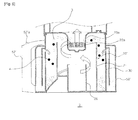
- FIG. 5 is a sectional view illustrating a dust collector 2 according to another embodiment of the present invention.
- the dust collector 2 includes a centrifuging unit 20' configured so as to discharge air upwards.
- a stabilizer 26 is formed at a base portion in a centrifuging tube 21.
- an exhaust tube 23a having a grill 22a is formed at an upper surface in a dust container which faces an opened upper portion of the centrifuging tube 21.
- a handle portion 52' of a water storage unit 50' has a ' ' shape, and is formed at an upper portion thereof with a water inlet 52a'.
- the dust collector of the present invention may be implemented in various forms, such as a dust collector including a centrifuging unit in which a rotational axis of air has a predetermined slant or is leaned in a horizontal direction, a dust collector which includes a first separation unit having a first cyclone and a second separation unit having a second cyclone, a dust collector in which a centrifuging unit is installed outside a dust container, etc.
- the above-mentioned dust collector according to each illustrated embodiment of the present invention may further include an opening and closing cover at a lower portion thereof so as to discharge waste containing dust and water.
- the opening and closing cover includes a sealing member to prevent leakage of water
- the water inlet 52a is provided with an airtight lid
- the cover 10 further includes fixing means so as not to be separated when the dust collector is overturned and a sealing means to prevent leakage of water.
- the present invention may be applied to cleaning apparatuses such as domestic, business, industrial cleaners, and the like.
Landscapes
- Engineering & Computer Science (AREA)
- Mechanical Engineering (AREA)
- Filters For Electric Vacuum Cleaners (AREA)
Applications Claiming Priority (2)
| Application Number | Priority Date | Filing Date | Title |
|---|---|---|---|
| KR1020090037702A KR101566204B1 (ko) | 2009-04-29 | 2009-04-29 | 진공청소기의 습식분리형 집진장치 |
| PCT/KR2010/000802 WO2010126222A2 (ko) | 2009-04-29 | 2010-02-09 | 진공청소기의 습식분리형 집진장치 |
Publications (2)
| Publication Number | Publication Date |
|---|---|
| EP2425757A2 true EP2425757A2 (de) | 2012-03-07 |
| EP2425757A4 EP2425757A4 (de) | 2018-02-28 |
Family
ID=43032640
Family Applications (1)
| Application Number | Title | Priority Date | Filing Date |
|---|---|---|---|
| EP10769867.2A Withdrawn EP2425757A4 (de) | 2009-04-29 | 2010-02-09 | Staubsammler mit nasstrennung für einen staubsauger |
Country Status (4)
| Country | Link |
|---|---|
| US (1) | US9039820B2 (de) |
| EP (1) | EP2425757A4 (de) |
| KR (1) | KR101566204B1 (de) |
| WO (1) | WO2010126222A2 (de) |
Cited By (1)
| Publication number | Priority date | Publication date | Assignee | Title |
|---|---|---|---|---|
| CN117695795A (zh) * | 2023-12-07 | 2024-03-15 | 连云港石化有限公司 | 一种气体中精密除油除尘的方法设备 |
Families Citing this family (12)
| Publication number | Priority date | Publication date | Assignee | Title |
|---|---|---|---|---|
| KR101018355B1 (ko) * | 2010-11-22 | 2011-03-04 | 주식회사 이에스피테크 | 세척수 분산홀이 형성된 습식 전기집진기용 집진극 |
| JP6252243B2 (ja) * | 2014-02-27 | 2017-12-27 | 富士電機株式会社 | 自動販売機 |
| KR102122860B1 (ko) * | 2014-03-19 | 2020-06-26 | 삼성전자주식회사 | 사이클론 집진장치 및 이를 구비한 진공 청소기 |
| KR101651782B1 (ko) | 2015-05-18 | 2016-08-26 | 조영삼 | 습식 진공청소기 |
| US10322873B2 (en) | 2016-12-28 | 2019-06-18 | Omachron Intellectual Property Inc. | Dust and allergen control for surface cleaning apparatus |
| US10464746B2 (en) | 2016-12-28 | 2019-11-05 | Omachron Intellectual Property Inc. | Dust and allergen control for surface cleaning apparatus |
| US10244910B2 (en) | 2016-12-28 | 2019-04-02 | Omachron Intellectual Property Inc. | Dust and allergen control for surface cleaning apparatus |
| US10244909B2 (en) | 2016-12-28 | 2019-04-02 | Omachron Intellectual Property Inc. | Dust and allergen control for surface cleaning apparatus |
| US10214349B2 (en) | 2016-12-28 | 2019-02-26 | Omachron Intellectual Property Inc. | Dust and allergen control for surface cleaning apparatus |
| KR102640752B1 (ko) | 2021-06-02 | 2024-02-27 | 홍성완 | 섬유상 담체를 포함하는 미세먼지 제거용 유동형 필터 및 그의 제조방법 |
| KR20240159364A (ko) | 2023-04-28 | 2024-11-05 | 홍성완 | 폴리프로필렌 섬유 담체를 포함하는 미세먼지 제거용 유동형 고효율 필터 및 그의 제조방법 |
| KR102709217B1 (ko) * | 2023-11-15 | 2024-09-23 | 한명엽 | 카페트 세탁 장치 |
Family Cites Families (11)
| Publication number | Priority date | Publication date | Assignee | Title |
|---|---|---|---|---|
| BE348089A (de) * | 1927-02-04 | |||
| US2527015A (en) * | 1945-06-07 | 1950-10-24 | Robert A Lhota | Air washing and cleaning apparatus |
| US3348830A (en) * | 1966-12-28 | 1967-10-24 | Combustion Eng | Combined wet scrubber and heat exchange apparatus |
| JP3710533B2 (ja) * | 1995-08-11 | 2005-10-26 | 熊取谷 稔 | 空気浄化装置 |
| JP3158044B2 (ja) * | 1996-03-25 | 2001-04-23 | シャープ株式会社 | サイクロン式湿式電気掃除機 |
| US7669282B2 (en) * | 2004-03-11 | 2010-03-02 | Lg Electronics Inc. | Vacuum cleaner |
| JP2006006837A (ja) * | 2004-06-29 | 2006-01-12 | Izumi Products Co | 湿式電気掃除機 |
| KR101223341B1 (ko) | 2005-08-13 | 2013-01-16 | 엘지전자 주식회사 | 진공 청소기 |
| JP2007111397A (ja) * | 2005-10-24 | 2007-05-10 | Izumi Products Co | 湿式電気掃除機 |
| JP2008029769A (ja) * | 2006-08-01 | 2008-02-14 | Sharp Corp | サイクロン式湿式電気掃除機 |
| KR100813537B1 (ko) | 2007-04-02 | 2008-03-17 | 한경희 | 스팀진공청소기 |
-
2009
- 2009-04-29 KR KR1020090037702A patent/KR101566204B1/ko not_active Expired - Fee Related
-
2010
- 2010-02-09 EP EP10769867.2A patent/EP2425757A4/de not_active Withdrawn
- 2010-02-09 WO PCT/KR2010/000802 patent/WO2010126222A2/ko not_active Ceased
- 2010-02-09 US US13/318,008 patent/US9039820B2/en active Active
Non-Patent Citations (1)
| Title |
|---|
| See references of WO2010126222A2 * |
Cited By (1)
| Publication number | Priority date | Publication date | Assignee | Title |
|---|---|---|---|---|
| CN117695795A (zh) * | 2023-12-07 | 2024-03-15 | 连云港石化有限公司 | 一种气体中精密除油除尘的方法设备 |
Also Published As
| Publication number | Publication date |
|---|---|
| EP2425757A4 (de) | 2018-02-28 |
| US20120111201A1 (en) | 2012-05-10 |
| WO2010126222A2 (ko) | 2010-11-04 |
| WO2010126222A3 (ko) | 2010-12-23 |
| US9039820B2 (en) | 2015-05-26 |
| KR20100118812A (ko) | 2010-11-08 |
| KR101566204B1 (ko) | 2015-11-05 |
Similar Documents
| Publication | Publication Date | Title |
|---|---|---|
| US9039820B2 (en) | Wet-separation type dust collector for vacuum | |
| CN101437435B (zh) | 具有可移除气旋阵列的真空清洁器 | |
| AU2007201420B2 (en) | Dust collector of vacuum cleaner | |
| US5599401A (en) | Portable, hand-held, self-contained multi-surface, hydro-cleaning apparatus | |
| AU2006246452B2 (en) | Cyclone dust collecting apparatus for vacuum cleaner | |
| KR102000611B1 (ko) | 진공 청소기 | |
| CN101449948B (zh) | 用于吸尘器的旋风分离装置及具有该装置的吸尘器 | |
| EP3337370B1 (de) | Zyklonstaubsammler und staubsauger damit | |
| CN101073480B (zh) | 真空吸尘器 | |
| JP2009504310A (ja) | アップライト型真空掃除機の集塵容器構造及びアップライト型真空掃除機の集塵容器カバー支持構造 | |
| KR860001634B1 (ko) | 건 · 습식 진공 소제기 | |
| JP6934595B2 (ja) | 加湿装置 | |
| CN100369572C (zh) | 复合型清洁器 | |
| EP4440396A1 (de) | Flächenreinigungsvorrichtung | |
| US8973213B2 (en) | Dust collection unit and vacuum cleaner with the same | |
| US20060277872A1 (en) | Vacuum cleaner | |
| EP4440397A1 (de) | Flächenreinigungsvorrichtung | |
| JP5209991B2 (ja) | バキュームクリーナ | |
| JP4015399B2 (ja) | 湿式集塵装置 | |
| KR101903223B1 (ko) | 습식 공기청정기의 공기정화 및 가습 방법 | |
| EP4440399A1 (de) | Rückgewinnungstank für eine oberflächenreinigungsvorrichtung | |
| WO2023099907A1 (en) | Separator for a carpet cleaning device | |
| GB2613666A (en) | Recovery tank for a surface cleaning device | |
| EP4440398A1 (de) | Flächenreinigungsvorrichtung | |
| KR100375624B1 (ko) | 진공 청소기의 유로 시스템 |
Legal Events
| Date | Code | Title | Description |
|---|---|---|---|
| PUAI | Public reference made under article 153(3) epc to a published international application that has entered the european phase |
Free format text: ORIGINAL CODE: 0009012 |
|
| 17P | Request for examination filed |
Effective date: 20111028 |
|
| AK | Designated contracting states |
Kind code of ref document: A2 Designated state(s): AT BE BG CH CY CZ DE DK EE ES FI FR GB GR HR HU IE IS IT LI LT LU LV MC MK MT NL NO PL PT RO SE SI SK SM TR |
|
| DAX | Request for extension of the european patent (deleted) | ||
| RAP1 | Party data changed (applicant data changed or rights of an application transferred) |
Owner name: SAMSUNG ELECTRONICS CO., LTD. |
|
| A4 | Supplementary search report drawn up and despatched |
Effective date: 20180131 |
|
| RIC1 | Information provided on ipc code assigned before grant |
Ipc: A47L 9/18 20060101ALI20180125BHEP Ipc: A47L 9/16 20060101AFI20180125BHEP |
|
| STAA | Information on the status of an ep patent application or granted ep patent |
Free format text: STATUS: THE APPLICATION IS DEEMED TO BE WITHDRAWN |
|
| 18D | Application deemed to be withdrawn |
Effective date: 20180901 |