EP2425754A1 - Vorrichtung zum Aufschäumen einer Flüssigkeit, die mit Auslassmitteln versehen ist, um einen Überschuss an Aufschäumgas austreten zu lassen - Google Patents
Vorrichtung zum Aufschäumen einer Flüssigkeit, die mit Auslassmitteln versehen ist, um einen Überschuss an Aufschäumgas austreten zu lassen Download PDFInfo
- Publication number
- EP2425754A1 EP2425754A1 EP10175236A EP10175236A EP2425754A1 EP 2425754 A1 EP2425754 A1 EP 2425754A1 EP 10175236 A EP10175236 A EP 10175236A EP 10175236 A EP10175236 A EP 10175236A EP 2425754 A1 EP2425754 A1 EP 2425754A1
- Authority
- EP
- European Patent Office
- Prior art keywords
- liquid
- frothing
- chamber
- gas
- frothed
- Prior art date
- Legal status (The legal status is an assumption and is not a legal conclusion. Google has not performed a legal analysis and makes no representation as to the accuracy of the status listed.)
- Withdrawn
Links
- 239000007788 liquid Substances 0.000 title claims abstract description 145
- 238000000926 separation method Methods 0.000 claims abstract description 17
- 238000000034 method Methods 0.000 claims description 29
- 239000000203 mixture Substances 0.000 claims description 25
- 230000008569 process Effects 0.000 claims description 20
- 230000001939 inductive effect Effects 0.000 claims description 6
- 230000007704 transition Effects 0.000 claims description 6
- 235000013361 beverage Nutrition 0.000 claims description 2
- 238000011144 upstream manufacturing Methods 0.000 claims description 2
- 230000003993 interaction Effects 0.000 abstract description 4
- 238000007599 discharging Methods 0.000 abstract description 3
- 239000008267 milk Substances 0.000 description 68
- 210000004080 milk Anatomy 0.000 description 68
- 235000013336 milk Nutrition 0.000 description 68
- 239000006260 foam Substances 0.000 description 17
- 230000033001 locomotion Effects 0.000 description 10
- 230000000694 effects Effects 0.000 description 6
- 230000001804 emulsifying effect Effects 0.000 description 6
- 238000010438 heat treatment Methods 0.000 description 6
- 239000012071 phase Substances 0.000 description 6
- 239000012530 fluid Substances 0.000 description 5
- 230000008901 benefit Effects 0.000 description 3
- 230000015572 biosynthetic process Effects 0.000 description 2
- 230000003247 decreasing effect Effects 0.000 description 2
- 238000013461 design Methods 0.000 description 2
- 238000002474 experimental method Methods 0.000 description 2
- 239000002245 particle Substances 0.000 description 2
- 230000035945 sensitivity Effects 0.000 description 2
- 230000009471 action Effects 0.000 description 1
- 230000001580 bacterial effect Effects 0.000 description 1
- 238000007664 blowing Methods 0.000 description 1
- 238000009833 condensation Methods 0.000 description 1
- 230000005494 condensation Effects 0.000 description 1
- 238000011109 contamination Methods 0.000 description 1
- 239000006071 cream Substances 0.000 description 1
- 230000001419 dependent effect Effects 0.000 description 1
- 239000006185 dispersion Substances 0.000 description 1
- 239000000839 emulsion Substances 0.000 description 1
- 239000003925 fat Substances 0.000 description 1
- 230000005484 gravity Effects 0.000 description 1
- 238000010348 incorporation Methods 0.000 description 1
- 239000007791 liquid phase Substances 0.000 description 1
- 238000004519 manufacturing process Methods 0.000 description 1
- 238000012986 modification Methods 0.000 description 1
- 230000004048 modification Effects 0.000 description 1
- 230000002265 prevention Effects 0.000 description 1
- 239000007787 solid Substances 0.000 description 1
- 238000004544 sputter deposition Methods 0.000 description 1
- 239000004575 stone Substances 0.000 description 1
Images

Classifications
-
- A—HUMAN NECESSITIES
- A47—FURNITURE; DOMESTIC ARTICLES OR APPLIANCES; COFFEE MILLS; SPICE MILLS; SUCTION CLEANERS IN GENERAL
- A47J—KITCHEN EQUIPMENT; COFFEE MILLS; SPICE MILLS; APPARATUS FOR MAKING BEVERAGES
- A47J31/00—Apparatus for making beverages
- A47J31/44—Parts or details or accessories of beverage-making apparatus
- A47J31/4485—Nozzles dispensing heated and foamed milk, i.e. milk is sucked from a milk container, heated and foamed inside the device, and subsequently dispensed from the nozzle
-
- A—HUMAN NECESSITIES
- A47—FURNITURE; DOMESTIC ARTICLES OR APPLIANCES; COFFEE MILLS; SPICE MILLS; SUCTION CLEANERS IN GENERAL
- A47J—KITCHEN EQUIPMENT; COFFEE MILLS; SPICE MILLS; APPARATUS FOR MAKING BEVERAGES
- A47J31/00—Apparatus for making beverages
- A47J31/44—Parts or details or accessories of beverage-making apparatus
- A47J31/4489—Steam nozzles, e.g. for introducing into a milk container to heat and foam milk
Definitions
- the present invention relates to a device for frothing a liquid, comprising a chamber which is provided with supply means for supplying the liquid to be frothed and frothing gas, and outlet means for letting out a mixture of the liquid and the frothing gas, i.e. the liquid in a frothed state.
- the present invention also relates to a method for frothing a liquid, wherein a predetermined amount of the liquid to be frothed is supplied to a chamber, wherein a gas for frothing the liquid is supplied to the chamber as well, wherein, inside the chamber, the liquid is mixed with the frothing gas, and wherein a mixture of the liquid and the frothing gas, i.e. the liquid in a frothed state, is allowed to flow out of the chamber.
- Frothing a liquid involves supplying a gas like air to the liquid and mixing the liquid with the gas, for the purpose of obtaining a mass of bubbles in the liquid, which is referred to as foam.
- the liquid to be frothed is milk.
- a device which is capable of frothing milk in a user-friendly manner. It is a well-known option to combine a frothing process of milk with a heating process of milk, wherein air is supplied to the milk for obtaining foam, and wherein steam is supplied to the milk for increasing the temperature of the milk.
- Applicant proposes a way of solving the problems as mentioned in the foregoing, which is the subject of European patent application 10166464.7 .
- Applicant proposes the use of a device in which the supply of gas for the purpose of frothing is not realized by using a hole or a channel providing access to a space where the frothing is supposed to take place.
- there are two separate spaces wherein one of the spaces is arranged such as to receive content from another of the spaces, and wherein a free space is present between the inlet of the one space and the outlet of the other space.
- gas that is present in the free space as mentioned is free to enter the spaces through their openings.
- a flow of gas can be obtained under the influence of a flow of liquid from one space to another, wherein the gas is taken along by the liquid as a secondary flow.
- the openings of the spaces and the free space between the inlet of the one space and the outlet of the other space are considerably larger than conventional holes or channels for supplying air, so that clogging is virtually impossible.
- the intake of frothing gas is not precisely controlled, and because of the fact that the intake is larger than in conventional situations, the amount of frothing gas is too much for the amount of liquid to be frothed. As a result, foam is obtained which is perceived as being "soapy" by users of the device, and which is not so stable.
- the object is achieved by means of a device for frothing a liquid, comprising a chamber which is provided with supply means for supplying the liquid to be frothed and frothing gas, and outlet means for letting out a mixture of the liquid and the frothing gas, i.e. the liquid in a frothed state, and for letting out excess frothing gas.
- the presence of at least one outlet for letting out excess frothing gas allows for a frothing process in which not all of the frothing gas that is present inside the chamber is used.
- it is possible to create foam with an acceptable quality irrespective of the amount of frothing gas that is supplied to the chamber in which the frothing process takes place, assuming that the amount of frothing gas is more than a minimum amount that is needed for allowing the foam to be formed.
- excess gas is the gas that is not used in the frothing process, and that is too much with respect to the amount of liquid in view of predetermined quality requirements of the foam.
- the chamber is adapted to allow for a cyclonic separation of the mixture of the liquid and the frothing gas that is obtained during operation of the device, from excess frothing gas.
- the chamber can be cylinder-shaped, and the means for supplying the liquid and the frothing gas can comprise a tube that has a tangential arrangement with respect to the chamber.
- the means for supplying the liquid and the frothing gas can comprise a tube that has a tangential arrangement with respect to the chamber.
- US 4,715,274 discloses an emulsifying unit which comprises a emulsifying chamber having an outward dispensing opening, nozzle means defining a steam delivery channel and terminating in a nozzle positioned spaced from said chamber to define a suction chamber, a milk intake conduit and an external air intake conduit communicating with said suction chamber which in turn communicates with said emulsifying chamber whereupon steam introduced into said steam delivery channel jets out of said nozzle creating a vacuum in said suction chamber drawing milk and air into same to mix and emulsify in said emulsifying chamber and to be discharged therefrom.
- the supply means of the chamber may also serve for supplying steam to the chamber.
- the supply means may also serve for supplying pressurized gas, for inducing a flow of the liquid.
- the outlet means of the device according to the present invention may comprise a single element.
- Such element may comprise a tube, wherein an outlet for letting out excess frothing gas is constituted by a central portion of the tube, whereas an outlet for letting out the mixture of the liquid and the frothing gas is constituted by another portion of the tube, namely a portion surrounding the central portion.
- This option is very well suitable in a context of a chamber which is adapted to function as a cyclonic separator, as described in the foregoing. Besides being very practical, this option has an unforeseen effect, which is very advantageous in the field of frothing and heating liquids at the same time.
- a diameter of the tube is larger than 10 mm.
- the chamber may be cylinder-shaped, as noted earlier, wherein a practical value of a diameter of the chamber is about 20 mm.
- a ratio of the value of a diameter of the tube and the value of a diameter of the chamber may be in a range of 0.75 to 1.
- the tube has the same diameter than the chamber.
- the tube is relatively large when conventional devices like the emulsifying unit known from US 4,715,274 are taken into account, in which the ratio as mentioned is far below 0.5.
- the device according to the present invention is suitable for allowing excess frothing gas to escape and avoiding interaction of excess frothing gas with a frothed liquid, whereas the conventional devices are not.
- the tube having the relatively large diameter there is an effect of the flow of excess air on the temperature of the frothed liquid which contributes to consistency of that temperature for different uses of the device, that is to say, uses with different initial temperatures of the liquid.
- the single element for letting out both the mixture of the liquid and the frothing gas, and the excess frothing gas comprises a tube
- the smooth transition comprises a rounded surface with a radius which is in a range of 0 to 3 mm.
- the device according to the present invention comprises a single element for supplying the liquid and the frothing gas to the chamber, wherein the chamber is cylinder-shaped, and wherein the element has a tangential arrangement with respect to the chamber.
- the supply element With this arrangement of the supply element, formation of a cyclone in the chamber is promoted, and the separation of the excess frothing gas from the frothed liquid is thereby guaranteed.
- there are two or even more supply elements in the device which all have a tangential arrangement with respect to the chamber.
- there may be two tangentially oriented supply elements wherein one of the elements serves for supplying liquid and steam, and wherein another of the elements serves for supplying steam and air.
- the device according to the present invention can take place in various ways.
- the device according to the present invention to be part of an assembly, which further comprises a liquid supply unit having an upstream arrangement with respect to the device as seen in a direction of a flow of the liquid to be frothed through the assembly, and having an outlet for allowing content from that supply unit to flow out of that supply unit, wherein the supply means of the device are open to the liquid supply unit, and are separated from the outlet of the liquid supply unit by a free space for containing the frothing gas and for allowing for a supply of the frothing gas to the supply means of the device under the influence of a flow of liquid from the liquid supply unit to the supply means of the device.
- the intake of frothing gas is not performed through a restriction.
- the supply means of the device may have an open side which faces the outlet of the liquid supply unit.
- the present invention also relates to an appliance which is suitable to be used for making a beverage such as coffee containing a frothed liquid, comprising a device according to the present invention for delivering the frothed liquid.
- the present invention relates to a method for frothing a liquid, wherein a predetermined amount of the liquid to be frothed is supplied to a chamber, wherein a gas for frothing the liquid is supplied to the chamber as well, in an amount that is higher than an amount that is needed for frothing the amount of the liquid to a predetermined extent, wherein, inside the chamber, the liquid is mixed with only a portion of the frothing gas, wherein a mixture of the liquid and the frothing gas, i.e. the liquid in a frothed state, is allowed to flow out of the chamber, and wherein the unused frothing gas is allowed to flow out of the chamber as well.
- the method can have various aspects, in conformity with many of the foregoing remarks relating to the device according to the present invention.
- the separation of the flows of the frothed liquid and the excess frothing gas may take place by performing a process of cyclonic separation of the mixture of the liquid and the frothing gas that is obtained, from the excess frothing gas, inside the chamber.
- the flow of the mixture of the liquid and the frothing gas out of the chamber and the flow of the unused frothing gas out of the chamber are combined, which has the advantage of decreasing a sensitivity to an inlet temperature of the liquid,
- the flow of the mixture of the liquid and the frothing gas out of the chamber may be made to surround the flow of the unused frothing gas out of the chamber.
- the method according to the present invention involves supplying liquid to be frothed and frothing gas to a chamber. It is an option to supply pressurized gas to the chamber as well, wherein this gas may be used for inducing a flow of the liquid. According to a very practical possibility, steam may be supplied to the chamber, which may have the function of inducing a flow of the liquid as mentioned, and an additional function of heating the liquid in the process.
- Figure 1 diagrammatically shows a cross-section of an embodiment of a frothing device 1 according to the present invention, and figure 2 shows a top view of the frothing device 1.
- the frothing device 1 comprises a chamber 10, which is provided with a supply tube 11 and an outlet tube 12.
- the chamber 10 is cylinder-shaped, and has a circular circumference.
- the outlet tube 12 extends in a direction in which a longitudinal axis of the chamber is extending, whereas the supply tube 11 has a tangential arrangement.
- milk, steam and air are supplied to the chamber 10, through the supply tube 11. Due to the tangential arrangement of the supply tube 11, the milk, the steam and the air collide with an interior surface 13 of the chamber 10 first, and are put in a cyclonic motion as a result of the collision and the bent shape of the interior surface 13, wherein a longitudinal axis of the cyclonic motion more or less coincides with the longitudinal axis of the chamber.
- the kinetic energy that is needed in the process is provided by the steam, which condenses in the milk. Due to the fact that there is motion of the milk, the steam and the air, air comes to mix with the milk, as a result of which frothed milk is obtained.
- the line 1 illustrates the fact that at a top side of the chamber 10, it is mostly air that is present there, which is logical in view of the fact that only the air tends to go up, whereas the frothed milk tends to go down.
- downwards from the supply tube 11 there is a considerable amount of milk froth besides the air.
- the air is free to escape, and the frothed milk can be received in a cup or the like.
- the path which is followed by the frothed milk on its way out is indicated by means of a bent arrow.
- the central portion of the outlet tube 12 through which the excess air is let out is indicated by means of dashed lines in figure 1 , wherein that portion of the outlet tube 12 is indicated by means of reference numeral 12', and wherein the other portion of the outlet tube 12, which has a function in letting out the frothed milk, is indicated by means of reference numeral 12".
- the chamber 10 of the frothing device 1 is designed such as to function as a separator, in which both centrifugal and cyclonic separation methods are applied.
- the design of this chamber 10 is different from conventional designs.
- the inlet is fed with a flow of gas or liquid, which serves as a continuous phase, in which another liquid or solid particles are dispersed.
- the continuous phase is steam, which during the frothing process will fully condense on the milk, which is the liquid phase.
- a third flow is the air, of which a portion should not mix with the milk.
- the air phase is also a continuous phase, probably already mixing with the steam.
- a volumetric input flow rate is much less than an output flow rate. This means that quite some kinetic energy is put into the separator, which is used to supply the energy that is needed for dispersing some of the air into the milk. Still, the frothed milk leaves the chamber 10 in a gentle way, driven by gravity through an outlet tube 12 in the bottom. The outlet which is present at the top in conventional separators for letting out the continuous phase is not needed, as all of the steam has condensed into the milk at the end of the frothing process. The excess air that was forced to the center of the cyclone leaves the cyclone through the same outlet tube 12 as the frothed milk. At this position, the flow is so gentle that no further mixing/dispersion takes place.
- the outlet tube 12 has a very large diameter compared to known frothing chambers. In general, the value of a diameter of an outlet of a device for frothing milk is below 10 mm.
- a large outlet tube 12 is advantageous, as such an outlet tube 12 is capable of accommodating a flow of the frothed milk as well as a flow of excess air, and is also capable of guaranteeing the prevention of blowing bubbles in the outlet tube 12.
- a suitable diameter is larger than 10 mm, and preferably ranges from 12 to 25 mm, more preferably from 15 to 20 mm. It is noted that in figure 1 , the diameter of the outlet tube 12 is indicated by a two-headed arrow d.
- An important factor in determining an appearance of the frothed milk is a ratio of the value of the diameter d of the outlet tube 12 and the value of a diameter of the chamber 10, as this ratio has a direct influence on the extent to which the fluids entering the chamber 10 through the supply tube 11 encounter frothed milk.
- a suitable range for this ratio has been found to be a range of 0.75 to 1. With a smaller ratio, there is risk that too much of the air is forced to mix with the milk. It is noted that in figure 1 , the diameter of the chamber 10 is indicated by a two-headed arrow D.
- the supply tube 11 is positioned tangentially with respect to the chamber 10. In this way, maximum rotation speed is realized.
- a level of the supply tube 11 in the chamber 10 is another factor determining the appearance of the frothed milk, as this also has a direct influence on the extent to which the fluids entering the chamber 10 through the supply tube 11 can interact with frothed milk that is already present in the chamber 10.
- the fluids enter at a relatively low position, i.e. at a position relatively close to the position where the outlet tube 12 is connected to the chamber 10, all air is directed into a continuum of frothed milk. As a result, all air is being entrained and a large amount of coarse foam is obtained.
- Another parameter that can have an effect on the process inside the chamber 10 is a radius at the position where the outlet tube 12 is connected to the chamber 10, which is indicated by R in figure 1 .
- R has a relatively large value
- the fine foam that is accumulated at an outside of the cyclone can flow more easily towards the outlet tube 12.
- R a radius at the position where the outlet tube 12 is connected to the chamber 10.
- an appropriate resistance for the foam to flow from the outside of the cyclone to the outlet tube 12 can be set.
- a height of the chamber 10 can be chosen such that the entire chamber 10 is used for temporarily storing the frothed milk and allowing the separation process to take place.
- the diameter d of the outlet tube 12 can be large enough to not be blocked by the frothed milk.
- the concept of having excess air in a frothing process in the first place is not known from the art, and therefore, there are no measures known from the art for handling the presence of excess air in a frothing device.
- the excess air can be supplied in various ways.
- the air can be introduced into the chamber 10 by an air pump, or by two separate venturis, wherein both venturis may be steam-driven, wherein one of the venturis may be used for supplying liquid to be frothed, and wherein another of the venturis may be used for supplying an abundant amount of air.
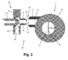
- FIG. 3 Another way in which an abundant supply of air can be obtained will now be described on the basis of figure 3 , in which an assembly 20 of which the frothing device 1 according to the present invention may be part is diagrammatically shown.
- the assembly 20 comprises a liquid supply unit 30.
- This unit 30 comprises an outlet nozzle 31 having an internal space 32, a steam supply channel 33 which is connected to the internal space 32 through a constriction 34, and a milk supply channel 35 which is connected to the internal space 32 through a restriction 36 as well, and which is extending perpendicular to the steam supply channel 33.
- the liquid supply unit 30 does not comprise an air supply channel.
- a frothing process does not take place in the internal space 32 of the outlet nozzle 31 of the liquid supply unit 30. Instead, a mixture of steam and milk is obtained, wherein the milk is drawn into the internal space 32 under the influence of the steam, and is heated by the steam. Furthermore, the mixture of steam and milk is discharged as a jet through an open side 37 of the internal space 32, which serves as an outlet 37 of the internal space 32.
- the supply tube 11 of the frothing device 1 has an internal space 14 and an open side 15 allowing access to the internal space 14 from the outside.
- the open side 15 as mentioned is present at a distance from the open side 37 of the internal space 32 of the outlet nozzle 31 of the liquid supply unit 30, in a concentric arrangement with the open side 37 of the internal space 32 of the outlet nozzle 31 of the liquid supply unit 30, wherein the open sides 15, 37 of the spaces 14, 32 are separated by a free space 40, i.e. by air.
- the open side 15 of the space 14 as mentioned has a larger area than the open side 37 of the space 32 of the liquid supply unit 30.
- the suction effect of the jet on the air may be quite low, but due to the fact that air can simply enter the internal space 14 of the supply tube 11 of the frothing device 1 from the free space 40, it is possible for the effect to be sufficient for actually causing a desired ingoing flow of air.
- FIG. 1 illustrates a practical option of applying a cross 16 inside the outlet tube 12 of the frothing device 1. On the basis of the presence of the cross 16, the rotational movement of the outgoing flows is stopped.
- a notable feature of the assembly 20 is the fact that the supply or air does not require the application of an air supply channel. Instead, a jet of a mixture of steam and milk is made to cross a distance between two spaces 14, 32, wherein an airflow is induced in that process. This means that the assembly 20 does not need an air supply channel. On the basis of this fact, there will be no problems of clogging as far as the supply of air is concerned. The free space 40 is simply too large. On the other hand, excess air is introduced into the frothing device 1, but this does not influence the quality of the frothed product as an advantageous result of the application of the frothing device 1 according to the present invention, which is adapted to function as a separator of frothed liquid and frothing gas.
- the steam supply channel 33 of the assembly 20 may be connected to any suitable means for delivering steam.
- the milk may be taken from any suitable reservoir.
- these components 1, 30 of the assembly 20 are separated by air.
- these components 1,30 may be interconnected at one or more other positions, and may be arranged in one supporting frame, for example.
- the frothing device 1 and the liquid supply unit 30 are individual units 1, 30 as far as their internal spaces 14, 32 are concerned, as these spaces 14, 32 are separated by air.
- the assembly 20 comprises the frothing device 1 which is adapted to be used as a separator of excess frothing gas and frothed liquid, a most practical and advantageous functioning of the assembly 20 is obtained, wherein the advantage of avoiding clogging of the intake of the frothing gas is combined with a possibility of realizing a desired froth quality by separating excess air from the frothed liquid and discharging the excess air from the frothing device 1.
- outlet 12 for letting out liquid in a frothed state, and excess air.
- the latter outlet may be arranged at the top of the chamber 10, for example.
- a device 1 for frothing a liquid comprises a chamber 10 which is provided with supply means 11 for supplying the liquid to be frothed and frothing gas, and outlet means 12 for letting out frothed liquid, and for letting out excess frothing gas.
- supply means 11 for supplying the liquid to be frothed and frothing gas
- outlet means 12 for letting out frothed liquid, and for letting out excess frothing gas.
- the amount of the air is precisely determined and controlled, so that a predetermined froth quality is guaranteed.
- the froth quality can still be achieved, namely by discharging the excess air, wherein interaction of the excess air with the frothed liquid is avoided.
- the chamber 10 may be adapted to perform a cyclonic separation process on the frothed liquid and the excess air.
- the outlet means may comprise a single tube-shaped element 12 for letting out both a flow of frothed liquid and a flow of excess air.
- this element 12 has a large diameter.
Landscapes
- Engineering & Computer Science (AREA)
- Food Science & Technology (AREA)
- Apparatus For Making Beverages (AREA)
- Food-Manufacturing Devices (AREA)
- Devices For Dispensing Beverages (AREA)
- Filling Of Jars Or Cans And Processes For Cleaning And Sealing Jars (AREA)
- Devices For Medical Bathing And Washing (AREA)
Priority Applications (8)
| Application Number | Priority Date | Filing Date | Title |
|---|---|---|---|
| EP10175236A EP2425754A1 (de) | 2010-09-03 | 2010-09-03 | Vorrichtung zum Aufschäumen einer Flüssigkeit, die mit Auslassmitteln versehen ist, um einen Überschuss an Aufschäumgas austreten zu lassen |
| JP2013526579A JP5976650B2 (ja) | 2010-09-03 | 2011-08-30 | 液体を泡立てるための装置 |
| CN201180042369.3A CN103108578B (zh) | 2010-09-03 | 2011-08-30 | 用于使液体起泡的装置 |
| PCT/IB2011/053786 WO2012029019A1 (en) | 2010-09-03 | 2011-08-30 | Device for frothing a liquid |
| BR112013004825A BR112013004825A2 (pt) | 2010-09-03 | 2011-08-30 | dispositivo (1) para espumar um líquido, conjunto (20), para espumar um líquido, aparelho e método para espumar líquidos |
| EP11761712.6A EP2611341B1 (de) | 2010-09-03 | 2011-08-30 | Vorrichtung zum aufschäumen einer flüssigkeit |
| RU2013114857/12A RU2567221C2 (ru) | 2010-09-03 | 2011-08-30 | Устройство для вспенивания жидкости |
| US13/818,710 US9392903B2 (en) | 2010-09-03 | 2011-08-30 | Device for frothing a liquid |
Applications Claiming Priority (1)
| Application Number | Priority Date | Filing Date | Title |
|---|---|---|---|
| EP10175236A EP2425754A1 (de) | 2010-09-03 | 2010-09-03 | Vorrichtung zum Aufschäumen einer Flüssigkeit, die mit Auslassmitteln versehen ist, um einen Überschuss an Aufschäumgas austreten zu lassen |
Publications (1)
| Publication Number | Publication Date |
|---|---|
| EP2425754A1 true EP2425754A1 (de) | 2012-03-07 |
Family
ID=43513684
Family Applications (2)
| Application Number | Title | Priority Date | Filing Date |
|---|---|---|---|
| EP10175236A Withdrawn EP2425754A1 (de) | 2010-09-03 | 2010-09-03 | Vorrichtung zum Aufschäumen einer Flüssigkeit, die mit Auslassmitteln versehen ist, um einen Überschuss an Aufschäumgas austreten zu lassen |
| EP11761712.6A Active EP2611341B1 (de) | 2010-09-03 | 2011-08-30 | Vorrichtung zum aufschäumen einer flüssigkeit |
Family Applications After (1)
| Application Number | Title | Priority Date | Filing Date |
|---|---|---|---|
| EP11761712.6A Active EP2611341B1 (de) | 2010-09-03 | 2011-08-30 | Vorrichtung zum aufschäumen einer flüssigkeit |
Country Status (7)
| Country | Link |
|---|---|
| US (1) | US9392903B2 (de) |
| EP (2) | EP2425754A1 (de) |
| JP (1) | JP5976650B2 (de) |
| CN (1) | CN103108578B (de) |
| BR (1) | BR112013004825A2 (de) |
| RU (1) | RU2567221C2 (de) |
| WO (1) | WO2012029019A1 (de) |
Cited By (1)
| Publication number | Priority date | Publication date | Assignee | Title |
|---|---|---|---|---|
| EP3437528A1 (de) | 2017-08-04 | 2019-02-06 | BSH Hausgeräte GmbH | Crema-aufschäumer |
Families Citing this family (2)
| Publication number | Priority date | Publication date | Assignee | Title |
|---|---|---|---|---|
| BR112015000334A2 (pt) | 2012-07-12 | 2017-06-27 | Koninklijke Philips Nv | dispositivo de formação de espuma em um líquido por meio de interação com um gás, dispositivo de preparo de bebidas e cafeteira |
| JP6383741B2 (ja) * | 2013-03-11 | 2018-08-29 | コーニンクレッカ フィリップス エヌ ヴェKoninklijke Philips N.V. | 液体泡立て装置 |
Citations (3)
| Publication number | Priority date | Publication date | Assignee | Title |
|---|---|---|---|---|
| US4715274A (en) | 1985-01-31 | 1987-12-29 | Spidem S.R.L. | Emulsifier unit particularly for emulsifying steam and milk to prepare cappuccinos and the like beverages |
| US5189949A (en) * | 1991-06-14 | 1993-03-02 | Vincenzo Apa | Cappuccino dispenser |
| US5615602A (en) * | 1994-12-27 | 1997-04-01 | J. Lough Limited | Emulsifying unit, particularly for emulsifying air and milk with steam to prepare cappuccino and the like |
Family Cites Families (7)
| Publication number | Priority date | Publication date | Assignee | Title |
|---|---|---|---|---|
| CA2046967C (en) * | 1990-07-20 | 1996-03-26 | Vincenzo Apa | Cappuccino dispenser |
| ES2287748T3 (es) | 2003-08-19 | 2007-12-16 | Koninklijke Philips Electronics N.V. | Dispositivo de preparacion de bebidas que comprende un elemento de produccion de espuma. |
| DE602005007183D1 (de) * | 2005-04-25 | 2008-07-10 | Nestec Sa | Aufschäumvorrichtung mit Schaumstromregelung |
| US8820214B2 (en) * | 2007-01-04 | 2014-09-02 | The Coca-Cola Company | System and method for producing foamed milk from powder |
| GB2454656A (en) | 2007-11-09 | 2009-05-20 | Kraft Foods R & D Inc | A beverage cartridge |
| CN201481104U (zh) * | 2009-08-27 | 2010-05-26 | 许庭祯 | 咖啡机的咖啡起泡装置 |
| RU2571198C2 (ru) | 2010-06-18 | 2015-12-20 | Конинклейке Филипс Электроникс Н.В. | Устройство для вспенивания жидкости |
-
2010
- 2010-09-03 EP EP10175236A patent/EP2425754A1/de not_active Withdrawn
-
2011
- 2011-08-30 WO PCT/IB2011/053786 patent/WO2012029019A1/en not_active Ceased
- 2011-08-30 US US13/818,710 patent/US9392903B2/en active Active
- 2011-08-30 JP JP2013526579A patent/JP5976650B2/ja not_active Expired - Fee Related
- 2011-08-30 BR BR112013004825A patent/BR112013004825A2/pt active Search and Examination
- 2011-08-30 RU RU2013114857/12A patent/RU2567221C2/ru active
- 2011-08-30 EP EP11761712.6A patent/EP2611341B1/de active Active
- 2011-08-30 CN CN201180042369.3A patent/CN103108578B/zh active Active
Patent Citations (4)
| Publication number | Priority date | Publication date | Assignee | Title |
|---|---|---|---|---|
| US4715274A (en) | 1985-01-31 | 1987-12-29 | Spidem S.R.L. | Emulsifier unit particularly for emulsifying steam and milk to prepare cappuccinos and the like beverages |
| US4715274B1 (en) | 1985-01-31 | 1994-05-24 | Spidem Srl | Emulsifier unit particularly for emulsifying stea m and milk to prepare cappuccinos and the like be verages |
| US5189949A (en) * | 1991-06-14 | 1993-03-02 | Vincenzo Apa | Cappuccino dispenser |
| US5615602A (en) * | 1994-12-27 | 1997-04-01 | J. Lough Limited | Emulsifying unit, particularly for emulsifying air and milk with steam to prepare cappuccino and the like |
Cited By (3)
| Publication number | Priority date | Publication date | Assignee | Title |
|---|---|---|---|---|
| EP3437528A1 (de) | 2017-08-04 | 2019-02-06 | BSH Hausgeräte GmbH | Crema-aufschäumer |
| DE102017213603A1 (de) | 2017-08-04 | 2019-02-07 | BSH Hausgeräte GmbH | Crema-Aufschäumer |
| DE102017213603B4 (de) | 2017-08-04 | 2020-01-02 | BSH Hausgeräte GmbH | Crema-Aufschäumer |
Also Published As
| Publication number | Publication date |
|---|---|
| US9392903B2 (en) | 2016-07-19 |
| CN103108578B (zh) | 2016-03-09 |
| EP2611341B1 (de) | 2013-12-11 |
| WO2012029019A1 (en) | 2012-03-08 |
| BR112013004825A2 (pt) | 2016-05-31 |
| RU2567221C2 (ru) | 2015-11-10 |
| RU2013114857A (ru) | 2014-10-10 |
| JP5976650B2 (ja) | 2016-08-24 |
| US20130155804A1 (en) | 2013-06-20 |
| JP2013536722A (ja) | 2013-09-26 |
| EP2611341A1 (de) | 2013-07-10 |
| CN103108578A (zh) | 2013-05-15 |
Similar Documents
| Publication | Publication Date | Title |
|---|---|---|
| EP2490963B1 (de) | Patrone zur zubereitung von getränken | |
| JP4921840B2 (ja) | 泡の流れ制御システムを備える蒸気式泡立て装置 | |
| JP4095034B2 (ja) | 上に泡層を有する飲料を作る飲料装置 | |
| US8460440B2 (en) | Beverage production device | |
| JP2005512715A5 (de) | ||
| EP2582271B1 (de) | Vorrichtung zum aufschäumen einer flüssigkeit | |
| JP6383741B2 (ja) | 液体泡立て装置 | |
| CN109152496A (zh) | 牛奶发泡设备的输出装置 | |
| EP1404201B1 (de) | Vorrichtung zum erhitzen und emulgieren von flüssigkeiten, insbesondere von getränken | |
| EP2425754A1 (de) | Vorrichtung zum Aufschäumen einer Flüssigkeit, die mit Auslassmitteln versehen ist, um einen Überschuss an Aufschäumgas austreten zu lassen | |
| HK1171999B (en) | Cartridge for the preparation of beverages | |
| HK40007416A (en) | Output device for a milk foaming apparatus |
Legal Events
| Date | Code | Title | Description |
|---|---|---|---|
| AK | Designated contracting states |
Kind code of ref document: A1 Designated state(s): AL AT BE BG CH CY CZ DE DK EE ES FI FR GB GR HR HU IE IS IT LI LT LU LV MC MK MT NL NO PL PT RO SE SI SK SM TR |
|
| AX | Request for extension of the european patent |
Extension state: BA ME RS |
|
| PUAI | Public reference made under article 153(3) epc to a published international application that has entered the european phase |
Free format text: ORIGINAL CODE: 0009012 |
|
| STAA | Information on the status of an ep patent application or granted ep patent |
Free format text: STATUS: THE APPLICATION IS DEEMED TO BE WITHDRAWN |
|
| 18D | Application deemed to be withdrawn |
Effective date: 20120908 |