EP2425677B1 - Structure de suscepteur ventilé - Google Patents
Structure de suscepteur ventilé Download PDFInfo
- Publication number
- EP2425677B1 EP2425677B1 EP10772476.7A EP10772476A EP2425677B1 EP 2425677 B1 EP2425677 B1 EP 2425677B1 EP 10772476 A EP10772476 A EP 10772476A EP 2425677 B1 EP2425677 B1 EP 2425677B1
- Authority
- EP
- European Patent Office
- Prior art keywords
- panel
- construct
- food item
- microwave energy
- dimension
- Prior art date
- Legal status (The legal status is an assumption and is not a legal conclusion. Google has not performed a legal analysis and makes no representation as to the accuracy of the status listed.)
- Active
Links
Images


Classifications
-
- H—ELECTRICITY
- H05—ELECTRIC TECHNIQUES NOT OTHERWISE PROVIDED FOR
- H05B—ELECTRIC HEATING; ELECTRIC LIGHT SOURCES NOT OTHERWISE PROVIDED FOR; CIRCUIT ARRANGEMENTS FOR ELECTRIC LIGHT SOURCES, IN GENERAL
- H05B6/00—Heating by electric, magnetic or electromagnetic fields
- H05B6/64—Heating using microwaves
- H05B6/647—Aspects related to microwave heating combined with other heating techniques
- H05B6/6491—Aspects related to microwave heating combined with other heating techniques combined with the use of susceptors
- H05B6/6494—Aspects related to microwave heating combined with other heating techniques combined with the use of susceptors for cooking
-
- A—HUMAN NECESSITIES
- A23—FOODS OR FOODSTUFFS; TREATMENT THEREOF, NOT COVERED BY OTHER CLASSES
- A23L—FOODS, FOODSTUFFS OR NON-ALCOHOLIC BEVERAGES, NOT OTHERWISE PROVIDED FOR; PREPARATION OR TREATMENT THEREOF
- A23L5/00—Preparation or treatment of foods or foodstuffs, in general; Food or foodstuffs obtained thereby; Materials therefor
- A23L5/10—General methods of cooking foods, e.g. by roasting or frying
- A23L5/15—General methods of cooking foods, e.g. by roasting or frying using wave energy, irradiation, electrical means or magnetic fields, e.g. oven cooking or roasting using radiant dry heat
Definitions
- This disclosure relates to various microwave energy interactive structures, packages, apparatuses, or constructs for heating, browning, and/or crisping a food item in a microwave oven.
- Microwave ovens provide a convenient means for heating a variety of food items, including sandwiches and other bread and/or dough-based products such as pizzas and pies.
- microwave ovens tend to cook such items unevenly and are unable to achieve the desired balance of thorough heating and a browned, crisp crust.
- improved materials, packages, and other constructs that provide the desired degree of heating, browning, and/or crisping of various food items in a microwave oven.
- US 2004/234653 A1 discloses a method of using a microwave heating construct, comprising: placing a food item on the construct, the food item having a surface to be browned and/or crisped, wherein the construct comprises a panel, the panel comprises microwave energy interactive material operative for converting at least a portion of impinging microwave energy into thermal energy, the panel includes an aperture, and the placing of the food item on the construct comprises placing the food item on the panel so that the surface of the food item is adjacent to the aperture.
- the invention is a method according to claim 1.
- the various constructs generally include at least two sections or panels that are partially joined to one another to define a gap or unjoined area between the panels.
- At least one panel for example, the panel intended for contact with the food item, includes one or more apertures that communicate with the unjoined area. The apertures cooperate with the unjoined area to assist with the transport or venting of moisture away from the food item to enhance the browning and/or crisping of the food item.
- one or both panels include a susceptor or susceptor layer, i.e., a thin layer of microwave energy interactive material (generally less than about 100 angstroms in thickness, for example, from about 60 to about 100 angstroms in thickness, and having an optical density of from about 0.15 to about 0.35, for example, about 0.17 to about 0.28) that tends to absorb at least a portion of impinging microwave energy and convert it to thermal energy (i.e., heat). The thermal energy then can be transferred to the food item to heat, brown, and/or crisp the food item.
- a susceptor or susceptor layer i.e., a thin layer of microwave energy interactive material (generally less than about 100 angstroms in thickness, for example, from about 60 to about 100 angstroms in thickness, and having an optical density of from about 0.15 to about 0.35, for example, about 0.17 to about 0.28) that tends to absorb at least a portion of impinging microwave energy and convert it to thermal energy (i.e., heat
- the arrangement of susceptors and/or apertures may be used to simulate the appearance of food items prepared using other conventional heating apparatuses, for example, grills or skillets.
- the arrangement of susceptors and/or apertures may be used to impart a logo, a graphic, product information, or any other indicia to the surface of the food item.
- the apparatus or construct may be used to prepare various food items in a microwave oven, for example, sandwiches, savory or sweet pastries, breaded food items, or any other food item that desirably is heated, browned, and/or crisped.
- the construct may be formed at least partially from a disposable material, for example, paper or paperboard.
- FIGS. 1A-1C schematically illustrate an exemplary microwave heating construct or apparatus 100 (e.g., a tray or card) for heating, browning, and/or crisping a food item F (shown schematically with dashed lines) in a microwave oven.
- FIG. 1A schematically illustrates a top plan view of a first side (e.g., top) of the construct 100
- FIG. 1B schematically illustrates an end elevation view of the construct 100 of FIG. 1A
- FIG. 1C schematically illustrates a top plan view of a second side (e.g., bottom) of the construct 100.
- the construct 100 has a generally rectangular shape suitable for receiving a somewhat elongate food item or a plurality of smaller food items thereon, for example, a French bread pizza, a filled pastry product, a breaded meat product, a calzone, a Stromboli, or any other suitable food item.
- the construct 100 may have any suitable shape needed or desired to prepare a particular food item (or items).
- the construct 100 and its various features or components generally have a first dimension, for example, a length, extending in a first direction, for example, a longitudinal direction, D1, and a second dimension, for example, a width, extending in a second direction, for example, a transverse direction, D2 . It will be understood that such designations are made only for convenience and do not necessarily refer to or limit the manner in which the construct is manufactured.
- the construct 100 may be symmetric or nearly symmetric about a transverse centerline CT and/or along a longitudinal centerline CL.
- the construct 100 includes a first panel 102 and a second panel 104 partially joined to one another to create a multilayer structure that includes an unjoined area or gap 106 between the panels 102, 104, as shown in FIG. 1B .
- the size of the gap is exaggerated for illustrative purposes in FIG. 1B and that the actual space or distance between the two panels 102, 104 may be very small, such that the panels 102, 104 may be at least partially contacting one another.
- the first panel 102 and the second panel 104 may be joined to one another adhesively or otherwise along an attachment area 108 (FIG. IB), for example, along a portion of the peripheral margin of the construct 100, or in any other suitable area of the construct 100.
- the construct 100 includes a single, substantially continuous attachment area 108, although other embodiments may include two or more attachment areas. At least a portion of the peripheral margin may remain unattached, for example, at least a portion of one or both ends 110 of the construct 100, as shown in FIG. 1B .
- One or both panels 102, 104 may include one or more venting apertures 112 that extend through the thickness of the respective panel 102, 104 to assist with the transport of moisture and other vapors away from the food item F and to further enhance browning and/or crisping.
- panel 102 includes a plurality of substantially circular apertures 112 arranged in rows extending substantially in the first direction D1.
- a first row of apertures 112 lies substantially along the longitudinal centerline CL, while second and third rows of apertures 112 lie between the first row and respective longitudinal edges 114 of the construct 100.
- the first row includes five apertures and the second and third rows each include four apertures.
- other shapes, numbers, and configurations of apertures may be used.
- Each panel 102, 104 includes a microwave energy interactive element 116a, 116b, for example, a susceptor or susceptor layer (shown schematically with stippling in FIGS. 1A and 1C ).
- Each susceptor layer 116a, 116b is operative for converting at least a portion of impinging microwave energy into thermal energy, which then can be transferred to the surface of the food item F.
- each susceptor layer 116a, 116b extends substantially to the various peripheral edges of the construct.
- the susceptor layer 116a, 116b may be used in only a portion of the construct 100.
- apertures 112 work in concert with the unjoined area or space 106 between the panels 102, 104 to provide a conduit for transporting moisture away from the food item, thereby allowing the food item to be browned and/or crisped more effectively.
- the food item F may be placed on a food-contacting surface 118 of the construct 100, in this example, such that the food item F is seated on at least a portion of the first panel 102.
- the susceptors 116a, 116b convert at least a portion of the impinging microwave energy into thermal energy, which then may brown and/or crisp the surface of the food item. Browning and/or crisping may be facilitated further by the apertures 110, void 106, and unjoined peripheral margin of panels 102, 104 along the end(s) 110 of the construct 100, which collectively allow any excess moisture to be carried away from the food item F.
- the weight of the food item may urge a portion of the first panel 102 towards the second panel 104, such that a portion of the first panel 102 is brought into contact with the second panel 104. In such areas, there may be little or no gap 106 between the panels 102, 104.
- paper-based materials e.g., paper and paperboard
- the panels 102, 104 may tend to curl slightly towards or away from each other.
- moisture from the food item may still be carried away from the food item to assist with browning and/or crisping. Some of such moisture may be adsorbed onto the interior sides of panels 102, 104, and/or may be absorbed into the material (e.g., fibers) forming the panels 102, 104. Other possibilities are contemplated.
- FIGS. 1D and 1E schematically depict opposite sides a blank 120 for forming the construct of FIGS. 1A-1C .
- FIG. ID schematically illustrates a side (e.g., a first side) of the blank 120 that forms an interior of the construct 100
- FIG. 1E schematically illustrates a side (e.g., a second side) of the blank 120 that forms exterior side of the construct 100.
- the blank 120 and its various features generally have a first dimension, for example, a length, extending in a first direction, for example, a longitudinal direction, D1, and a second dimension, for example, a width, extending in a second direction, for example, a transverse direction, D2 . It will be understood that such designations are made only for convenience and do not necessarily refer to or limit the manner in which the blank is manufactured or erected into a construct.
- the blank 120 may include some features that are symmetric or nearly symmetric about a transverse centerline CT and/or along a longitudinal centerline CL.
- the blank 120 includes a pair of panels 102, 104 foldably joined to one another along a longitudinal line of disruption 122, for example, a fold line, score line, or the like, extending substantially along the longitudinal centerline CL of the blank 120.
- the longitudinal line of disruption 122 may be spaced slightly from the longitudinal centerline CL in a manner that assists with the formation of a gap or void 106 between the panels 102, 104.
- the blank may include additional panels for forming a construct with side walls that define a gap between the panels. Such side walls may be gusseted if desired.
- the opposite marginal areas of panels 102, 104 serve as attachment or glue areas 108 for joining the panels 102, 104 to one another.
- the attachment area(s) may have any other suitable location.
- a plurality of apertures 112 extend through the thickness of panel 102.
- each panel 102, 104 generally may comprise a plurality of adjoined layers.
- Each panel 102, 104 may comprise substantially the same arrangement of layers, for example, where the panels 102, 104 are formed from a single sheet of material, or may comprise different arrangements of layers, for example, where the construct 100 is formed from separate panels 102, 104.
- the number, type, and arrangement of layers in each panel may vary depending on the heating, browning, and/or crisping needs for a particular application. Thus, numerous possibilities are contemplated.
- each panel 102, 104 includes a layer of microwave energy interactive material 116 operative as a susceptor (i.e., susceptors or susceptor layers 116a, 116b ) supported on a substantially microwave energy transparent material 124, for example, a polymer film, to form a susceptor film 126.
- the layer of microwave energy interactive material 116 may be joined to a support layer 128 (e.g., paper or paperboard) using an adhesive or other suitable material (not shown). Apertures 112 extend through the thickness of panel 102.
- an adhesive material 130 may be applied to the attachment area 108 ( FIG. 1G ) of one or both panels 102, 104, folding panel 102 towards panel 104 along line of disruption 122 ( FIG. 1H ), and bringing the peripheral edges of panels 102, 104 into alignment with one another ( FIG 1I ) to join the panels 102, 104 to one another.
- numerous other methods of forming the construct 100 may be used.
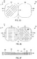
- FIGS. 2A-2I schematically depict an exemplary variation of the microwave heating apparatus or construct 100 of FIGS. 1A-1C and blank 120 of FIGS. 1D-1F for forming the apparatus of FIGS. 1A-1C .
- the apparatus 200 and blank 220 include features that are similar to the apparatus 100 and blank 120 shown in FIGS. 1A-1F , except for variations noted and variations that will be understood by those of skill in the art.
- An exemplary method of forming the construct 200 from the blank 220 is illustrated schematically in FIGS. 2G-2I .
- the reference numerals of similar features are preceded in the figures with a "2" instead of a " 1 ".
- the construct 200 has a generally square shape with rounded corners suitable for receiving a somewhat square and/or rounded food item or a plurality of smaller food items thereon, for example, a pizza, an open faced sandwich, a filled pastry product, a breaded meat product, a calzone, a Stromboli, or any other suitable food item.
- a pizza an open faced sandwich
- a filled pastry product a breaded meat product
- a calzone a Stromboli, or any other suitable food item.
- numerous other shapes are contemplated.
- the apertures 212 comprise a plurality of elongate cutouts or slots extending in a direction oblique to the first direction D1 and the second direction D2. More particularly, the apertures 212 are aligned in a direction substantially parallel to a first diagonal centerline CD1 and in a direction substantially perpendicular to a second diagonal centerline CD2. In this example, the apertures are arranged in two groups on opposite sides of the second diagonal centerline CD2.
- any suitable shape, size, orientation, and arrangement of apertures may be used for a particular heating application.
- the apertures may have rounded corners. Numerous other possibilities are contemplated.
- the construct 200 may be formed in the manner described in connection with FIGS. 1G-1I , as shown schematically in FIGS. 2G-2I .
- the susceptors 216a, 216b Upon sufficient exposure to microwave energy, the susceptors 216a, 216b convert at least a portion of the impinging microwave energy into thermal energy, which then may brown and/or crisp the surface of the food item. Less heat may be generated in the areas including the apertures 212, since only susceptor 216b is present, while more heat may be generated in the remaining areas where both susceptors 216a, 216b are present. As a result, the food item may be browned and/or crisped somewhat less in the areas adjacent to the apertures 212.
- the overall pattern of browning and/or crisping may resemble grill marks, such that the lighter and darker areas resemble the markings that may be obtained by heating a food item on a grill. Browning and/or crisping may be facilitated further by the transport of moisture away from the food item F via apertures 212, the unjoined area or gap 206 between the panels 202, 204, and the open end(s) 210 of the construct
- the food item F may be a sandwich that has been separated into two sections, each including a piece of bread and one or more toppings in an "open face" configuration. After heating, the components of the sandwich may be stacked on top of one another in a facing relationship to form a double faced sandwich.
- both the bread and the "filling" of a sandwich may be desirably browned and/or crisped.
- the filling for example, a breaded meat item, may be placed on one part of the construct, while the bread may be placed on the other, for example. If desired, the user may be instructed to invert or "flip" one or both items during heating to brown and/or crisp the opposite side of the respective item.
- the sandwich includes two pieces of bread (i.e., where the sandwich is a double faced sandwich)
- the user may be instructed to replace the browned and/or crisped bread with the other piece, so that both pieces may be browned and/or crisped.
- both pieces may be browned and/or crisped.
- microwave heating constructs are encompassed by the disclosure. Any of such constructs may be formed from various materials, provided that the materials are substantially resistant to softening, scorching, combusting, or degrading at typical microwave oven heating temperatures, for example, at from about 250°F to about 425°F.
- the materials may include microwave energy interactive materials, for example, those used to form susceptors (e.g., susceptors or susceptor layers 116a, 116b, 216a, 216b ) and other microwave energy interactive elements, and microwave energy transparent or inactive materials, for example, those used to form the remainder of the construct.
- the microwave energy interactive material may be an electroconductive or semiconductive material, for example, a vacuum deposited metal or metal alloy, or a metallic ink, an organic ink, an inorganic ink, a metallic paste, an organic paste, an inorganic paste, or any combination thereof.
- metals and metal alloys that may be suitable include, but are not limited to, aluminum, chromium, copper, inconel alloys (nickel-chromium-molybdenum alloy with niobium), iron, magnesium, nickel, stainless steel, tin, titanium, tungsten, and any combination or alloy thereof.
- the microwave energy interactive material may comprise a metal oxide, for example, oxides of aluminum, iron, and tin, optionally used in conjunction with an electrically conductive material.
- a metal oxide for example, oxides of aluminum, iron, and tin
- ITO indium tin oxide
- the microwave energy interactive material may comprise a suitable electroconductive, semiconductive, or non-conductive artificial dielectric or ferroelectric.
- Artificial dielectrics comprise conductive, subdivided material in a polymeric or other suitable matrix or binder, and may include flakes of an electroconductive metal, for example, aluminum.
- the microwave energy interactive material may be carbon-based, for example, as disclosed in U.S. Patent Nos. 4,943,456 , 5,002,826 , 5,118,747 , and 5,410,135 .
- the microwave energy interactive material may interact with the magnetic portion of the electromagnetic energy in the microwave oven. Correctly chosen materials of this type can self-limit based on the loss of interaction when the Curie temperature of the material is reached.
- An example of such an interactive coating is described in U.S. Patent No. 4,283,427 .
- the construct may include other microwave energy interactive elements.
- the construct may include a foil or high optical density evaporated material having a thickness sufficient to reflect a substantial portion of impinging microwave energy.
- Such elements typically are formed from a conductive, reflective metal or metal alloy, for example, aluminum, copper, or stainless steel, in the form of a solid "patch" generally having a thickness of from about 0.000285 inches (0.007239 mm) to about 0.005 inches (0.127 mm), for example, from about 0.0003 inches (0.00762 mm) to about 0.003 inches (0.0762 mm).
- Other such elements may have a thickness of from about 0.00035 inches (0.00889 mm) to about 0.002 inches (0.0508 mm), for example, 0.0016 inches (0.04064 mm).
- microwave energy reflecting (or reflective) elements may be used as shielding elements where the food item is prone to scorching or drying out during heating.
- smaller microwave energy reflecting elements may be used to diffuse or lessen the intensity of microwave energy.
- One example of a material utilizing such microwave energy reflecting elements is commercially available from Graphic Packaging International, Inc. (Marietta, GA) under the trade name MicroRite® packaging material.
- a plurality of microwave energy reflecting elements may be arranged to form a microwave energy distributing element to direct microwave energy to specific areas of the food item. If desired, the loops may be of a length that causes microwave energy to resonate, thereby enhancing the distribution effect.
- Microwave energy distributing elements are described in U.S. Patent Nos. 6,204,492 , 6,433,322 , 6,552,315 , and 6,677,563 .
- the construct may include a microwave energy interactive insulating material.
- a microwave energy interactive insulating material examples are provided in U.S. Patent No. 7,019,271 , U.S. Patent No. 7,351,942 , and U.S. Patent Application Publication No. 2008/0078759 A1, published April 3, 2008 .
- any of the numerous microwave energy interactive elements e.g., susceptors, foils, etc.
- the breaks or apertures may extend through the entire structure, or only through one or more layers.
- the number, shape, size, and positioning of such breaks or apertures may vary for a particular application depending on the type of construct being formed, the food item to be heated therein or thereon, the desired degree of heating, browning, and/or crisping, whether direct exposure to microwave energy is needed or desired to attain uniform heating of the food item, the need for regulating the change in temperature of the food item through direct heating, and whether and to what extent there is a need for venting.
- a microwave energy interactive element may include one or more transparent areas to effect dielectric heating of the food item.
- the microwave energy interactive element comprises a susceptor
- such apertures decrease the total microwave energy interactive area, and therefore, decrease the amount of microwave energy interactive material available for heating, browning, and/or crisping the surface of the food item.
- the relative amounts of microwave energy interactive areas and microwave energy transparent areas must be balanced to attain the desired overall heating characteristics for the particular food item.
- one or more portions of the susceptor may be designed to be microwave energy inactive to ensure that the microwave energy is focused efficiently on the areas to be heated, browned, and/or crisped, rather than being lost to portions of the food item not intended to be browned and/or crisped or to the heating environment.
- the susceptor may incorporate one or more "fuse" elements that limit the propagation of cracks in the susceptor structure, and thereby control overheating, in areas of the susceptor structure where heat transfer to the food is low and the susceptor might tend to become too hot.
- the size and shape of the fuses may be varied as needed. Examples of susceptors including such fuses are provided, for example, in U.S. Patent No. 5,412,187 , U.S. Patent No. 5,530,231 , U.S. Patent Application Publication No. US 2008/0035634A1, published February 14, 2008 , and PCT Application Publication No. WO 2007/127371, published November 8, 2007 .
- any of such discontinuities or apertures may comprise a physical aperture or void (e.g., apertures 112, 212 ) in one or more layers or materials used to form the structure or construct.
- a physical aperture also provides a venting function to allow steam or other vapors or liquids released from the food item to be carried away from the food item.
- the microwave energy interactive element may be supported on a microwave inactive or transparent substrate 124, 224 ( FIGS. 1F and 2F ), for example, a polymer film or other suitable polymeric material, for ease of handling and/or to prevent contact between the microwave energy interactive material and the food item.
- the outermost surface of the polymer film may define at least a portion of the food-contacting surface of the package (e.g., surface 118, 218 of respective polymer film 124, 224 ) .
- polymer films that may be suitable include, but are not limited to, polyolefins, polyesters, polyamides, polyimides, polysulfones, polyether ketones, cellophanes, or any combination thereof.
- the polymer film comprises polyethylene terephthalate.
- the thickness of the film generally may be from about 35 gauge to about 10 mil. In each of various examples, the thickness of the film may be from about 40 to about 80 gauge, from about 45 to about 50 gauge, about 48 gauge, or any other suitable thickness.
- Other non-conducting substrate materials such as paper and paper laminates, metal oxides, silicates, cellulosics, or any combination thereof, also may be used.
- the polymer film may undergo one or more treatments to modify the surface prior to depositing the microwave energy interactive material onto the polymer film.
- the polymer film may undergo a plasma treatment to modify the roughness of the surface of the polymer film. While not wishing to be bound by theory, it is believed that such surface treatments may provide a more uniform surface for receiving the microwave energy interactive material, which in turn, may increase the heat flux and maximum temperature of the resulting susceptor structure. Such treatments are discussed in U.S. Patent Application No. 12/709,578, filed February 22, 2010 .
- the microwave energy interactive material may be applied to the substrate in any suitable manner, and in some instances, the microwave energy interactive material is printed on, extruded onto, sputtered onto, evaporated on, or laminated to the substrate.
- the microwave energy interactive material may be applied to the substrate in any pattern, and using any technique, to achieve the desired heating effect of the food item.
- the microwave energy interactive material may be provided as a continuous or discontinuous layer or coating including circles, loops, hexagons, islands, squares, rectangles, octagons, and so forth.
- the construct may be formed at least partially from a polymer or polymeric material.
- all or a portion the construct may be formed from a paper or paperboard material.
- the paper may have a basis weight of about 25 lbs/ream (40,69 g/m 2 ).
- the paperboard may have a basis weight of from about 60 to about 330 lbs/ream (97,66 to about 537,11 g/ m 2 ), for example, from about 155 to about 265 lbs/ream (252,28 to about 431,32 g/m 2 ).
- the paperboard may have a basis weight of about 175 lbs/ream (284,83 g/m 2 ).
- the paperboard generally may have a thickness of from about 6 to about 30 mils (0.1524 to about 0.762 mm), for example, from about 14 to about 24 mils (0.3556 to about 0.6096 mm).
- the paperboard may have a thickness of about 16 mils (0.4064 mm).
- Any suitable paperboard may be used, for example, a solid bleached or solid unbleached sulfate board, such as SUS® board, commercially available from Graphic Packaging International.
- the construct may be formed according to numerous processes known to those in the art, including using adhesive bonding, thermal bonding, ultrasonic bonding, mechanical stitching, or any other suitable process. Any of the various components used to form the construct may be provided as a sheet of material, a roll of material, or a die cut material in the shape of the package to be formed (e.g., a blank).
- a first apparatus was similar the apparatus of FIGS. 1A-1C .
- a second apparatus was similar to the first apparatus, except that the first panel and the second panel were joined substantially continuously to one another, such that there was little or no gap between the panels.
- Each Stromboli was heated on the respective apparatus for about 3 minutes in an 1100 W Panasonic microwave oven that included a turntable. After heating, the bottom of each Stromboli was examined. The Stromboli heated on the first apparatus was heated, browned, and crisped suitably, while the Stromboli heated on the second apparatus was not browned or crisped to the desired level.
- a first apparatus was similar the apparatus of FIGS. 2A-2C .
- a second apparatus was a microwave heating tray seated on a carton.
- a third apparatus was similar to the first apparatus, except that the first panel and the second panel were joined substantially continuously to one another, such that there was little or no gap between the panels.
- the third apparatus also was substantially octagonal in shape.
- Each Panini was heated on the respective apparatus for about 3 minutes in an 1100 W Panasonic microwave oven that included a turntable.
- the Panini heated on the first apparatus was heated, browned, and crisped suitably, while the Paninis heated on the second and third apparatuses were not browned or crisped to the desired level.
- a first apparatus was similar the apparatus of FIGS. 1A-1C , except the arrangement of apertures differed from the apparatus of FIGS. 1A-1C . Further, the apertures were formed manually by punching a die or other suitable implement into the food-contacting panel, thereby partially striking flap-like tabs from the panel. (Such tabs or protrusions may have extended somewhat into the gap, such that the tabs or protrusions may have assisted with maintaining a space between the panels.)
- a second apparatus was a single layer susceptor tray with side walls including apertures.
- Each flatbread pizza was heated on the respective apparatus for about 2 minutes in an 1100 W Panasonic microwave oven that included a turntable. After heating, the bottom of each flatbread pizza was examined. The flatbread pizza heated on the first apparatus was heated, browned, and crisped suitably, while the flatbread pizza heated on the second apparatus was not browned or crisped to the desired level.
Landscapes
- Physics & Mathematics (AREA)
- Electromagnetism (AREA)
- Polymers & Plastics (AREA)
- Chemical & Material Sciences (AREA)
- Engineering & Computer Science (AREA)
- Food Science & Technology (AREA)
- Health & Medical Sciences (AREA)
- Life Sciences & Earth Sciences (AREA)
- Nutrition Science (AREA)
- Cookers (AREA)
- Package Specialized In Special Use (AREA)
- Electric Ovens (AREA)
- Constitution Of High-Frequency Heating (AREA)
Claims (14)
- Procédé pour l'utilisation d'une construction de chauffage à microondes (100 ; 200) comprenant :la disposition d'un produit alimentaire (F) sur la construction, le produit alimentaire présentant une surface destinée à être brunie et/ou rendue croustillante, dans lequella construction comprend un premier panneau (102 ; 202) et un deuxième panneau (104 ; 204) reliés l'un à l'autre dans une relation opposée en face-à-face, le premier panneau et le deuxième panneau étant partiellement reliés l'un à l'autre de telle façon qu'une zone non reliée (106 ; 206) est définie entre le premier panneau et le deuxième panneau, la zone non reliée étant en communication avec un bord périphérique ouvert (110 ; 210) de la construction,le premier panneau et le deuxième panneau comprennent chacun un matériau sensible à l'énergie micro-onde (116a, 116b ; 216a, 216b) opérationnel pour convertir au moins une partie de l'énergie micro-onde incidente en énergie thermique,le premier panneau comprend une ouverture (112 ; 212) en communication avec la zone non reliée entre le premier panneau et le deuxième panneau, etla disposition du produit alimentaire sur la construction comprend la disposition du produit alimentaire sur le premier panneau de manière à ce que la surface du produit alimentaire soit adjacente à l'ouverture, de manière à ce que la surface du produit alimentaire soit en communication avec la zone non reliée entre le premier panneau et le deuxième panneau.
- Procédé selon la revendication 1, dans lequel l'ouverture présente une forme substantiellement circulaire.
- Procédé selon la revendication 1, dans lequel l'ouverture présente une forme substantiellement allongée.
- Procédé selon l'une quelconque des revendications 1 à 3, dans lequel l'ouverture est une première ouverture parmi une pluralité d'ouvertures.
- Procédé selon l'une quelconque des revendications 1 à 4, dans lequel le deuxième panneau comprend une ouverture en communication avec la zone non reliée entre le premier panneau et le deuxième panneau.
- Procédé selon l'une quelconque des revendications 1 à 5, dans lequel le premier panneau et le deuxième panneau sont reliés l'un à l'autre le long d'une partie au moins de zones de bord respectives du premier panneau et du deuxième panneau.
- Procédé selon la revendication 6, dans lequel les zones de bord respectives du premier panneau et du deuxième panneau comprennent des bords périphériques opposés du premier panneau et du deuxième panneau.
- Procédé selon la revendication 7, dans lequel
la construction présente une première dimension (D1) s'étendant dans une première direction et une deuxième dimension (D2) s'étendant le long d'une deuxième direction substantiellement perpendiculaire à la première direction,
les zones de bord respectives du premier panneau et du deuxième panneau s'étendent le long de la première dimension de la construction, et
l'extrémité périphérique ouverte de la construction s'étend le long de la deuxième dimension de la construction. - Procédé selon la revendication 8, dans lequel
l'extrémité périphérique ouverte de la construction est une première extrémité périphérique ouverte de la construction, et
la construction comprend une deuxième extrémité périphérique ouverte le long de la deuxième dimension de la construction, opposée à la première extrémité périphérique ouverte de la construction. - Procédé selon la revendication 8 ou 9, dans lequel la première dimension de la construction est plus grande que la deuxième dimension de la construction.
- Procédé selon la revendication 8 ou 9, dans lequel la première dimension de la construction est substantiellement égale à la deuxième dimension de la construction.
- Procédé selon l'une quelconque des revendications 1 à 11, dans lequel le matériau sensible à l'énergie micro-onde présente une densité optique comprise entre environ 0,17 et environ 0,28.
- Procédé selon l'une quelconque des revendications 1 à 12, comprenant en outre l'exposition du produit alimentaire à l'énergie micro-onde sur la construction, de telle façon que
le matériau sensible à l'énergie micro-onde convertir au moins une partie de l'énergie micro-onde en chaleur, et
la chaleur est transmise au produit alimentaire pour au moins brunir et/ou faire croustiller la surface du produit alimentaire. - Procédé selon la revendication 13, dans lequel de l'humidité s'échappe du produit alimentaire lorsque la chaleur est transmise au produit alimentaire, et
au moins une partie de l'humidité est évacuée du produit alimentaire au moins à travers l'ouverture et la zone non reliée entre le premier panneau et le deuxième panneau de la construction.
Applications Claiming Priority (2)
| Application Number | Priority Date | Filing Date | Title |
|---|---|---|---|
| US21475809P | 2009-04-28 | 2009-04-28 | |
| PCT/US2010/032336 WO2010129205A2 (fr) | 2009-04-28 | 2010-04-26 | Structure de suscepteur ventilé |
Publications (3)
| Publication Number | Publication Date |
|---|---|
| EP2425677A2 EP2425677A2 (fr) | 2012-03-07 |
| EP2425677A4 EP2425677A4 (fr) | 2013-07-03 |
| EP2425677B1 true EP2425677B1 (fr) | 2018-10-24 |
Family
ID=42991211
Family Applications (1)
| Application Number | Title | Priority Date | Filing Date |
|---|---|---|---|
| EP10772476.7A Active EP2425677B1 (fr) | 2009-04-28 | 2010-04-26 | Structure de suscepteur ventilé |
Country Status (6)
| Country | Link |
|---|---|
| US (2) | US8658952B2 (fr) |
| EP (1) | EP2425677B1 (fr) |
| JP (1) | JP5559307B2 (fr) |
| CA (1) | CA2757009C (fr) |
| ES (1) | ES2697532T3 (fr) |
| WO (1) | WO2010129205A2 (fr) |
Families Citing this family (8)
| Publication number | Priority date | Publication date | Assignee | Title |
|---|---|---|---|---|
| JP5265765B2 (ja) * | 2008-06-09 | 2013-08-14 | グラフィック パッケージング インターナショナル インコーポレイテッド | 微小孔を有するマイクロ波エネルギー相互作用構造体 |
| WO2010129205A2 (fr) | 2009-04-28 | 2010-11-11 | Graphic Packaging International, Inc. | Structure de suscepteur ventilé |
| US9586746B2 (en) | 2012-06-11 | 2017-03-07 | Sfc Global Supply Chain, Inc. | Microwave package for single-step cooking of multi-component foodstuffs |
| US9334100B2 (en) | 2012-07-18 | 2016-05-10 | Sfc Global Supply Chain, Inc. | Patterned dual susceptor |
| CN203604279U (zh) * | 2013-10-31 | 2014-05-21 | 富鼎电子科技(嘉善)有限公司 | 真空发生器 |
| US10251223B2 (en) * | 2015-05-20 | 2019-04-02 | Illinois Tool Works Inc. | Apparatus for providing customizable heat zones in an oven |
| US10840114B1 (en) | 2016-07-26 | 2020-11-17 | Raytheon Company | Rapid thermal anneal apparatus and method |
| WO2019156703A1 (fr) * | 2018-02-12 | 2019-08-15 | Graphic Packaging International, Llc | Structure stratifiée, construction et leurs procédés d'utilisation |
Family Cites Families (61)
| Publication number | Priority date | Publication date | Assignee | Title |
|---|---|---|---|---|
| US4268738A (en) | 1977-09-28 | 1981-05-19 | The Procter & Gamble Company | Microwave energy moderator |
| US4283427A (en) * | 1978-12-19 | 1981-08-11 | The Pillsbury Company | Microwave heating package, method and susceptor composition |
| JPS6366703A (ja) | 1986-09-08 | 1988-03-25 | Nec Home Electronics Ltd | 複合型磁気ヘツドの製造方法 |
| JPS6386075A (ja) | 1986-09-30 | 1988-04-16 | Toshiba Corp | Cadシステム |
| JPS6386075U (fr) * | 1986-11-26 | 1988-06-04 | ||
| USRE34683E (en) | 1987-03-10 | 1994-08-02 | James River Corporation Of Virginia | Control of microwave interactive heating by patterned deactivation |
| US4865921A (en) | 1987-03-10 | 1989-09-12 | James Riker Corporation Of Virginia | Microwave interactive laminate |
| US4775771A (en) | 1987-07-30 | 1988-10-04 | James River Corporation | Sleeve for crisping and browning of foods in a microwave oven and package and method utilizing same |
| CA1292934C (fr) | 1988-05-20 | 1991-12-10 | Donald G. Beckett | Materiau de rechauffement et cuisson aux micro-ondes |
| US5410135A (en) | 1988-09-01 | 1995-04-25 | James River Paper Company, Inc. | Self limiting microwave heaters |
| US5118747A (en) | 1988-09-01 | 1992-06-02 | James River Corporation Of Virginia | Microwave heater compositions for use in microwave ovens |
| US4943456A (en) | 1988-09-01 | 1990-07-24 | James River Corporation Of Virginia | Microwave reactive heater |
| US5002826A (en) | 1988-09-01 | 1991-03-26 | James River Corporation Of Virginia | Heaters for use in microwave ovens |
| US4890439A (en) | 1988-11-09 | 1990-01-02 | James River Corporation | Flexible disposable material for forming a food container for microwave cooking |
| JPH02128838A (ja) | 1988-11-09 | 1990-05-17 | Asahi Chem Ind Co Ltd | 電子レンジ加熱用調理紙 |
| GB8827759D0 (en) | 1988-11-28 | 1988-12-29 | Beckett D E | Selective microwave heating material-ii |
| US5519195A (en) | 1989-02-09 | 1996-05-21 | Beckett Technologies Corp. | Methods and devices used in the microwave heating of foods and other materials |
| CA2009207A1 (fr) | 1990-02-02 | 1991-08-02 | D. Gregory Beckett | Cuisson controlee des aliments par miro-ondes |
| JPH0483132A (ja) | 1990-07-25 | 1992-03-17 | Matsushita Electric Ind Co Ltd | 三次元スキャナ |
| US5434393A (en) | 1990-10-09 | 1995-07-18 | Jurkofsky; Maryann | Microwave cooking bag with extension as handling vehicle |
| US5170025A (en) | 1990-12-20 | 1992-12-08 | The Pillsbury Company | Two-sided susceptor structure |
| US5266386A (en) | 1991-02-14 | 1993-11-30 | Beckett Industries Inc. | Demetallizing procedure |
| US5628921A (en) | 1991-02-14 | 1997-05-13 | Beckett Technologies Corp. | Demetallizing procedure |
| CA2041062C (fr) | 1991-02-14 | 2000-11-28 | D. Gregory Beckett | Procede de demetallisation |
| US5213902A (en) | 1991-02-19 | 1993-05-25 | Beckett Industries Inc. | Microwave oven package |
| US5221419A (en) | 1991-02-19 | 1993-06-22 | Beckett Industries Inc. | Method for forming laminate for microwave oven package |
| US5260537A (en) | 1991-06-17 | 1993-11-09 | Beckett Industries Inc. | Microwave heating structure |
| JP3058950B2 (ja) | 1991-07-19 | 2000-07-04 | ヤンマーディーゼル株式会社 | 舶用減速逆転機のスラスト支持装置 |
| GB9201932D0 (en) | 1992-01-29 | 1992-03-18 | Beckett Ind Inc | Novel microwave heating structure |
| US5424517A (en) | 1993-10-27 | 1995-06-13 | James River Paper Company, Inc. | Microwave impedance matching film for microwave cooking |
| US5412187A (en) | 1994-01-25 | 1995-05-02 | Advanced Deposition Technologies, Inc. | Fused microwave conductive structure |
| US5530231A (en) | 1994-01-25 | 1996-06-25 | Advanced Deposition Technologies, Inc. | Multilayer fused microwave conductive structure |
| US5759422A (en) | 1996-02-14 | 1998-06-02 | Fort James Corporation | Patterned metal foil laminate and method for making same |
| US5800724A (en) | 1996-02-14 | 1998-09-01 | Fort James Corporation | Patterned metal foil laminate and method for making same |
| EP0921992B1 (fr) | 1996-08-26 | 2001-11-21 | Graphic Packaging Corporation | Recipient pouvant avoir une fonction de micro-onde |
| AU4006197A (en) | 1996-08-26 | 1998-03-19 | Fort James Corporation | Microwavable package |
| EP0891285B1 (fr) | 1997-01-29 | 2003-11-05 | Graphic Packaging Corporation | Element chauffant a boucles brisees pour four a micro-ondes |
| US6414290B1 (en) | 1998-03-19 | 2002-07-02 | Graphic Packaging Corporation | Patterned microwave susceptor |
| US6433322B2 (en) | 1999-09-20 | 2002-08-13 | Graphic Packaging Corporation | Abuse-tolerant metallic packaging materials for microwave cooking |
| US6204492B1 (en) | 1999-09-20 | 2001-03-20 | Graphic Packaging Corporation | Abuse-tolerant metallic packaging materials for microwave cooking |
| EP1132317A1 (fr) | 2000-03-10 | 2001-09-12 | Societe Des Produits Nestle S.A. | Suscepteur pour le chauffage d'un produit plat de pâte dans un four à micro-ondes |
| JP2001348075A (ja) | 2000-06-02 | 2001-12-18 | Toppan Printing Co Ltd | 吸水吸油機能を付与した電子レンジ調理用包装シート |
| ATE287839T1 (de) * | 2000-11-16 | 2005-02-15 | Steen Pedersen | Verpackung zur verwendung zum kochen von teigen und nahrungsmitteln in einer mikrowelle |
| US6717121B2 (en) | 2001-09-28 | 2004-04-06 | Graphic Packaging International, Inc. | Patterned microwave susceptor element and microwave container incorporating same |
| US6677563B2 (en) | 2001-12-14 | 2004-01-13 | Graphic Packaging Corporation | Abuse-tolerant metallic pattern arrays for microwave packaging materials |
| EP2181939B1 (fr) | 2002-02-08 | 2015-05-20 | Graphic Packaging International, Inc. | Matériel pour emballage interactif aux micro-ondes |
| US20040234653A1 (en) * | 2003-05-22 | 2004-11-25 | Cogley Paul A. | Susceptor tray and mirowavable dough products |
| WO2005056387A1 (fr) | 2003-11-13 | 2005-06-23 | Steamway Franchise Sales, Inc. | Dispositif pour cuisson aux micro-ondes a effet rissolant |
| AU2003304706A1 (en) | 2003-12-31 | 2005-08-03 | E.I. Du Pont De Nemours And Company | High temperature microwave susceptor structure |
| US8203107B2 (en) * | 2004-05-27 | 2012-06-19 | Mastrad, S.A. | Microwavable cooking implements and methods for crisping food items using the same |
| ATE547348T1 (de) | 2004-08-25 | 2012-03-15 | Graphic Packaging Int Inc | Absorbierende mikrowellen-interaktive verpackung |
| US20060289519A1 (en) * | 2005-05-20 | 2006-12-28 | Exopack-Technology, Llc | Microwave cooking package for food products and associated methods |
| US20070221666A1 (en) | 2006-03-09 | 2007-09-27 | Keefe Daniel J | Susceptor with apertured support |
| WO2007127371A2 (fr) | 2006-04-27 | 2007-11-08 | Graphic Packaging International, Inc. | Suscepteur à fusible multidirectionnel |
| BRPI0711290B1 (pt) * | 2006-05-12 | 2019-11-19 | Graphic Packaging Int Llc | folha para aquecimento interativo para energia de microondas, e método para usar a folha para aquecimento interativo para energia de microondas |
| WO2007146650A2 (fr) * | 2006-06-14 | 2007-12-21 | The Glad Products Company | Poche adaptée pour un four à micro-ondes ou matériau en feuille |
| US20080245787A1 (en) | 2007-04-03 | 2008-10-09 | Joseph Lambert | Controlling and moderating microwave energy in concurrent multiple sample well applications |
| EP2176139B1 (fr) * | 2007-08-13 | 2016-03-23 | Graphic Packaging International, Inc. | Flan pour la formation d'une structure de chauffage par micro-ondes |
| JP5265765B2 (ja) | 2008-06-09 | 2013-08-14 | グラフィック パッケージング インターナショナル インコーポレイテッド | 微小孔を有するマイクロ波エネルギー相互作用構造体 |
| US8710410B2 (en) * | 2008-09-07 | 2014-04-29 | Kraft Foods Group Brands Llc | Tray for microwave cooking and folding of a food product |
| WO2010129205A2 (fr) | 2009-04-28 | 2010-11-11 | Graphic Packaging International, Inc. | Structure de suscepteur ventilé |
-
2010
- 2010-04-26 WO PCT/US2010/032336 patent/WO2010129205A2/fr not_active Ceased
- 2010-04-26 US US12/766,983 patent/US8658952B2/en active Active
- 2010-04-26 EP EP10772476.7A patent/EP2425677B1/fr active Active
- 2010-04-26 JP JP2012508558A patent/JP5559307B2/ja not_active Expired - Fee Related
- 2010-04-26 CA CA2757009A patent/CA2757009C/fr active Active
- 2010-04-26 ES ES10772476T patent/ES2697532T3/es active Active
-
2014
- 2014-01-10 US US14/152,611 patent/US9066375B2/en active Active
Non-Patent Citations (1)
| Title |
|---|
| None * |
Also Published As
| Publication number | Publication date |
|---|---|
| WO2010129205A2 (fr) | 2010-11-11 |
| CA2757009A1 (fr) | 2010-11-11 |
| JP5559307B2 (ja) | 2014-07-23 |
| EP2425677A4 (fr) | 2013-07-03 |
| ES2697532T3 (es) | 2019-01-24 |
| US9066375B2 (en) | 2015-06-23 |
| CA2757009C (fr) | 2015-08-25 |
| EP2425677A2 (fr) | 2012-03-07 |
| JP2012525561A (ja) | 2012-10-22 |
| US8658952B2 (en) | 2014-02-25 |
| US20100270294A1 (en) | 2010-10-28 |
| WO2010129205A3 (fr) | 2011-01-20 |
| US20140127368A1 (en) | 2014-05-08 |
Similar Documents
| Publication | Publication Date | Title |
|---|---|---|
| EP2422137B1 (fr) | Structure de suscepteur multicouche | |
| US10351329B2 (en) | Apparatus for preparing a food item in a microwave oven | |
| US9066375B2 (en) | Vented susceptor structure | |
| EP2510285B1 (fr) | Construction de chauffage de plat profond par micro-ondes | |
| US20110024413A1 (en) | Construct for Browning and Crisping a Food Item in a Microwave Oven | |
| US20100065556A1 (en) | Construct for Browning and Crisping a Food Item in a Microwave Oven | |
| CA2748919C (fr) | Construction elevee de chauffage a micro-ondes | |
| EP2507558B1 (fr) | Appareil de chauffage à micro-ondes muni d'éléments d'évacuation | |
| EP2630410B1 (fr) | Appareil de chauffage par micro-ondes pour aliment avec surface incurvée |
Legal Events
| Date | Code | Title | Description |
|---|---|---|---|
| PUAI | Public reference made under article 153(3) epc to a published international application that has entered the european phase |
Free format text: ORIGINAL CODE: 0009012 |
|
| 17P | Request for examination filed |
Effective date: 20111117 |
|
| AK | Designated contracting states |
Kind code of ref document: A2 Designated state(s): AT BE BG CH CY CZ DE DK EE ES FI FR GB GR HR HU IE IS IT LI LT LU LV MC MK MT NL NO PL PT RO SE SI SK SM TR |
|
| DAX | Request for extension of the european patent (deleted) | ||
| A4 | Supplementary search report drawn up and despatched |
Effective date: 20130603 |
|
| RIC1 | Information provided on ipc code assigned before grant |
Ipc: H05B 6/80 20060101ALI20130527BHEP Ipc: H05B 6/64 20060101AFI20130527BHEP |
|
| 17Q | First examination report despatched |
Effective date: 20141017 |
|
| RAP1 | Party data changed (applicant data changed or rights of an application transferred) |
Owner name: GRAPHIC PACKAGING INTERNATIONAL, LLC |
|
| GRAP | Despatch of communication of intention to grant a patent |
Free format text: ORIGINAL CODE: EPIDOSNIGR1 |
|
| STAA | Information on the status of an ep patent application or granted ep patent |
Free format text: STATUS: GRANT OF PATENT IS INTENDED |
|
| INTG | Intention to grant announced |
Effective date: 20180515 |
|
| GRAS | Grant fee paid |
Free format text: ORIGINAL CODE: EPIDOSNIGR3 |
|
| GRAA | (expected) grant |
Free format text: ORIGINAL CODE: 0009210 |
|
| STAA | Information on the status of an ep patent application or granted ep patent |
Free format text: STATUS: THE PATENT HAS BEEN GRANTED |
|
| AK | Designated contracting states |
Kind code of ref document: B1 Designated state(s): AT BE BG CH CY CZ DE DK EE ES FI FR GB GR HR HU IE IS IT LI LT LU LV MC MK MT NL NO PL PT RO SE SI SK SM TR |
|
| REG | Reference to a national code |
Ref country code: GB Ref legal event code: FG4D |
|
| REG | Reference to a national code |
Ref country code: CH Ref legal event code: EP |
|
| REG | Reference to a national code |
Ref country code: IE Ref legal event code: FG4D |
|
| REG | Reference to a national code |
Ref country code: AT Ref legal event code: REF Ref document number: 1058233 Country of ref document: AT Kind code of ref document: T Effective date: 20181115 |
|
| REG | Reference to a national code |
Ref country code: DE Ref legal event code: R096 Ref document number: 602010054607 Country of ref document: DE |
|
| REG | Reference to a national code |
Ref country code: ES Ref legal event code: FG2A Ref document number: 2697532 Country of ref document: ES Kind code of ref document: T3 Effective date: 20190124 |
|
| REG | Reference to a national code |
Ref country code: NL Ref legal event code: MP Effective date: 20181024 |
|
| REG | Reference to a national code |
Ref country code: LT Ref legal event code: MG4D |
|
| REG | Reference to a national code |
Ref country code: AT Ref legal event code: MK05 Ref document number: 1058233 Country of ref document: AT Kind code of ref document: T Effective date: 20181024 |
|
| PG25 | Lapsed in a contracting state [announced via postgrant information from national office to epo] |
Ref country code: NL Free format text: LAPSE BECAUSE OF FAILURE TO SUBMIT A TRANSLATION OF THE DESCRIPTION OR TO PAY THE FEE WITHIN THE PRESCRIBED TIME-LIMIT Effective date: 20181024 |
|
| PG25 | Lapsed in a contracting state [announced via postgrant information from national office to epo] |
Ref country code: LV Free format text: LAPSE BECAUSE OF FAILURE TO SUBMIT A TRANSLATION OF THE DESCRIPTION OR TO PAY THE FEE WITHIN THE PRESCRIBED TIME-LIMIT Effective date: 20181024 Ref country code: NO Free format text: LAPSE BECAUSE OF FAILURE TO SUBMIT A TRANSLATION OF THE DESCRIPTION OR TO PAY THE FEE WITHIN THE PRESCRIBED TIME-LIMIT Effective date: 20190124 Ref country code: LT Free format text: LAPSE BECAUSE OF FAILURE TO SUBMIT A TRANSLATION OF THE DESCRIPTION OR TO PAY THE FEE WITHIN THE PRESCRIBED TIME-LIMIT Effective date: 20181024 Ref country code: IS Free format text: LAPSE BECAUSE OF FAILURE TO SUBMIT A TRANSLATION OF THE DESCRIPTION OR TO PAY THE FEE WITHIN THE PRESCRIBED TIME-LIMIT Effective date: 20190224 Ref country code: AT Free format text: LAPSE BECAUSE OF FAILURE TO SUBMIT A TRANSLATION OF THE DESCRIPTION OR TO PAY THE FEE WITHIN THE PRESCRIBED TIME-LIMIT Effective date: 20181024 Ref country code: FI Free format text: LAPSE BECAUSE OF FAILURE TO SUBMIT A TRANSLATION OF THE DESCRIPTION OR TO PAY THE FEE WITHIN THE PRESCRIBED TIME-LIMIT Effective date: 20181024 Ref country code: BG Free format text: LAPSE BECAUSE OF FAILURE TO SUBMIT A TRANSLATION OF THE DESCRIPTION OR TO PAY THE FEE WITHIN THE PRESCRIBED TIME-LIMIT Effective date: 20190124 Ref country code: PL Free format text: LAPSE BECAUSE OF FAILURE TO SUBMIT A TRANSLATION OF THE DESCRIPTION OR TO PAY THE FEE WITHIN THE PRESCRIBED TIME-LIMIT Effective date: 20181024 Ref country code: HR Free format text: LAPSE BECAUSE OF FAILURE TO SUBMIT A TRANSLATION OF THE DESCRIPTION OR TO PAY THE FEE WITHIN THE PRESCRIBED TIME-LIMIT Effective date: 20181024 |
|
| PG25 | Lapsed in a contracting state [announced via postgrant information from national office to epo] |
Ref country code: SE Free format text: LAPSE BECAUSE OF FAILURE TO SUBMIT A TRANSLATION OF THE DESCRIPTION OR TO PAY THE FEE WITHIN THE PRESCRIBED TIME-LIMIT Effective date: 20181024 Ref country code: PT Free format text: LAPSE BECAUSE OF FAILURE TO SUBMIT A TRANSLATION OF THE DESCRIPTION OR TO PAY THE FEE WITHIN THE PRESCRIBED TIME-LIMIT Effective date: 20190224 Ref country code: GR Free format text: LAPSE BECAUSE OF FAILURE TO SUBMIT A TRANSLATION OF THE DESCRIPTION OR TO PAY THE FEE WITHIN THE PRESCRIBED TIME-LIMIT Effective date: 20190125 |
|
| REG | Reference to a national code |
Ref country code: DE Ref legal event code: R097 Ref document number: 602010054607 Country of ref document: DE |
|
| PG25 | Lapsed in a contracting state [announced via postgrant information from national office to epo] |
Ref country code: DK Free format text: LAPSE BECAUSE OF FAILURE TO SUBMIT A TRANSLATION OF THE DESCRIPTION OR TO PAY THE FEE WITHIN THE PRESCRIBED TIME-LIMIT Effective date: 20181024 Ref country code: CZ Free format text: LAPSE BECAUSE OF FAILURE TO SUBMIT A TRANSLATION OF THE DESCRIPTION OR TO PAY THE FEE WITHIN THE PRESCRIBED TIME-LIMIT Effective date: 20181024 Ref country code: IT Free format text: LAPSE BECAUSE OF FAILURE TO SUBMIT A TRANSLATION OF THE DESCRIPTION OR TO PAY THE FEE WITHIN THE PRESCRIBED TIME-LIMIT Effective date: 20181024 |
|
| PG25 | Lapsed in a contracting state [announced via postgrant information from national office to epo] |
Ref country code: RO Free format text: LAPSE BECAUSE OF FAILURE TO SUBMIT A TRANSLATION OF THE DESCRIPTION OR TO PAY THE FEE WITHIN THE PRESCRIBED TIME-LIMIT Effective date: 20181024 Ref country code: EE Free format text: LAPSE BECAUSE OF FAILURE TO SUBMIT A TRANSLATION OF THE DESCRIPTION OR TO PAY THE FEE WITHIN THE PRESCRIBED TIME-LIMIT Effective date: 20181024 Ref country code: SM Free format text: LAPSE BECAUSE OF FAILURE TO SUBMIT A TRANSLATION OF THE DESCRIPTION OR TO PAY THE FEE WITHIN THE PRESCRIBED TIME-LIMIT Effective date: 20181024 Ref country code: SK Free format text: LAPSE BECAUSE OF FAILURE TO SUBMIT A TRANSLATION OF THE DESCRIPTION OR TO PAY THE FEE WITHIN THE PRESCRIBED TIME-LIMIT Effective date: 20181024 |
|
| PLBE | No opposition filed within time limit |
Free format text: ORIGINAL CODE: 0009261 |
|
| STAA | Information on the status of an ep patent application or granted ep patent |
Free format text: STATUS: NO OPPOSITION FILED WITHIN TIME LIMIT |
|
| 26N | No opposition filed |
Effective date: 20190725 |
|
| PG25 | Lapsed in a contracting state [announced via postgrant information from national office to epo] |
Ref country code: SI Free format text: LAPSE BECAUSE OF FAILURE TO SUBMIT A TRANSLATION OF THE DESCRIPTION OR TO PAY THE FEE WITHIN THE PRESCRIBED TIME-LIMIT Effective date: 20181024 |
|
| REG | Reference to a national code |
Ref country code: CH Ref legal event code: PL |
|
| REG | Reference to a national code |
Ref country code: BE Ref legal event code: MM Effective date: 20190430 |
|
| PG25 | Lapsed in a contracting state [announced via postgrant information from national office to epo] |
Ref country code: MC Free format text: LAPSE BECAUSE OF FAILURE TO SUBMIT A TRANSLATION OF THE DESCRIPTION OR TO PAY THE FEE WITHIN THE PRESCRIBED TIME-LIMIT Effective date: 20181024 Ref country code: LU Free format text: LAPSE BECAUSE OF NON-PAYMENT OF DUE FEES Effective date: 20190426 |
|
| PG25 | Lapsed in a contracting state [announced via postgrant information from national office to epo] |
Ref country code: LI Free format text: LAPSE BECAUSE OF NON-PAYMENT OF DUE FEES Effective date: 20190430 Ref country code: CH Free format text: LAPSE BECAUSE OF NON-PAYMENT OF DUE FEES Effective date: 20190430 |
|
| PG25 | Lapsed in a contracting state [announced via postgrant information from national office to epo] |
Ref country code: BE Free format text: LAPSE BECAUSE OF NON-PAYMENT OF DUE FEES Effective date: 20190430 |
|
| PG25 | Lapsed in a contracting state [announced via postgrant information from national office to epo] |
Ref country code: TR Free format text: LAPSE BECAUSE OF FAILURE TO SUBMIT A TRANSLATION OF THE DESCRIPTION OR TO PAY THE FEE WITHIN THE PRESCRIBED TIME-LIMIT Effective date: 20181024 |
|
| PG25 | Lapsed in a contracting state [announced via postgrant information from national office to epo] |
Ref country code: IE Free format text: LAPSE BECAUSE OF NON-PAYMENT OF DUE FEES Effective date: 20190426 |
|
| PG25 | Lapsed in a contracting state [announced via postgrant information from national office to epo] |
Ref country code: CY Free format text: LAPSE BECAUSE OF FAILURE TO SUBMIT A TRANSLATION OF THE DESCRIPTION OR TO PAY THE FEE WITHIN THE PRESCRIBED TIME-LIMIT Effective date: 20181024 |
|
| PG25 | Lapsed in a contracting state [announced via postgrant information from national office to epo] |
Ref country code: MT Free format text: LAPSE BECAUSE OF FAILURE TO SUBMIT A TRANSLATION OF THE DESCRIPTION OR TO PAY THE FEE WITHIN THE PRESCRIBED TIME-LIMIT Effective date: 20181024 Ref country code: HU Free format text: LAPSE BECAUSE OF FAILURE TO SUBMIT A TRANSLATION OF THE DESCRIPTION OR TO PAY THE FEE WITHIN THE PRESCRIBED TIME-LIMIT; INVALID AB INITIO Effective date: 20100426 |
|
| PG25 | Lapsed in a contracting state [announced via postgrant information from national office to epo] |
Ref country code: MK Free format text: LAPSE BECAUSE OF FAILURE TO SUBMIT A TRANSLATION OF THE DESCRIPTION OR TO PAY THE FEE WITHIN THE PRESCRIBED TIME-LIMIT Effective date: 20181024 |
|
| PGFP | Annual fee paid to national office [announced via postgrant information from national office to epo] |
Ref country code: DE Payment date: 20250429 Year of fee payment: 16 |
|
| PGFP | Annual fee paid to national office [announced via postgrant information from national office to epo] |
Ref country code: GB Payment date: 20250428 Year of fee payment: 16 Ref country code: ES Payment date: 20250505 Year of fee payment: 16 |
|
| PGFP | Annual fee paid to national office [announced via postgrant information from national office to epo] |
Ref country code: FR Payment date: 20250425 Year of fee payment: 16 |