EP2425494B1 - Cabel connection device - Google Patents
Cabel connection device Download PDFInfo
- Publication number
- EP2425494B1 EP2425494B1 EP10722928.8A EP10722928A EP2425494B1 EP 2425494 B1 EP2425494 B1 EP 2425494B1 EP 10722928 A EP10722928 A EP 10722928A EP 2425494 B1 EP2425494 B1 EP 2425494B1
- Authority
- EP
- European Patent Office
- Prior art keywords
- cable
- connection device
- cable connection
- opening
- core
- Prior art date
- Legal status (The legal status is an assumption and is not a legal conclusion. Google has not performed a legal analysis and makes no representation as to the accuracy of the status listed.)
- Not-in-force
Links
- 239000004020 conductor Substances 0.000 claims description 11
- 230000006835 compression Effects 0.000 claims description 9
- 238000007906 compression Methods 0.000 claims description 9
- 238000005304 joining Methods 0.000 claims description 2
- 238000007789 sealing Methods 0.000 description 11
- 238000009413 insulation Methods 0.000 description 7
- 238000006073 displacement reaction Methods 0.000 description 5
- 210000003462 vein Anatomy 0.000 description 3
- 238000010276 construction Methods 0.000 description 2
- 239000000463 material Substances 0.000 description 2
- 230000001154 acute effect Effects 0.000 description 1
- 238000009826 distribution Methods 0.000 description 1
- 238000005516 engineering process Methods 0.000 description 1
- 238000009434 installation Methods 0.000 description 1
- 230000007774 longterm Effects 0.000 description 1
- 238000004519 manufacturing process Methods 0.000 description 1
- 238000000034 method Methods 0.000 description 1
- 230000035515 penetration Effects 0.000 description 1
Images

Classifications
-
- H—ELECTRICITY
- H01—ELECTRIC ELEMENTS
- H01R—ELECTRICALLY-CONDUCTIVE CONNECTIONS; STRUCTURAL ASSOCIATIONS OF A PLURALITY OF MUTUALLY-INSULATED ELECTRICAL CONNECTING ELEMENTS; COUPLING DEVICES; CURRENT COLLECTORS
- H01R13/00—Details of coupling devices of the kinds covered by groups H01R12/70 or H01R24/00 - H01R33/00
- H01R13/46—Bases; Cases
- H01R13/502—Bases; Cases composed of different pieces
-
- H—ELECTRICITY
- H01—ELECTRIC ELEMENTS
- H01R—ELECTRICALLY-CONDUCTIVE CONNECTIONS; STRUCTURAL ASSOCIATIONS OF A PLURALITY OF MUTUALLY-INSULATED ELECTRICAL CONNECTING ELEMENTS; COUPLING DEVICES; CURRENT COLLECTORS
- H01R9/00—Structural associations of a plurality of mutually-insulated electrical connecting elements, e.g. terminal strips or terminal blocks; Terminals or binding posts mounted upon a base or in a case; Bases therefor
- H01R9/03—Connectors arranged to contact a plurality of the conductors of a multiconductor cable, e.g. tapping connections
-
- H—ELECTRICITY
- H01—ELECTRIC ELEMENTS
- H01R—ELECTRICALLY-CONDUCTIVE CONNECTIONS; STRUCTURAL ASSOCIATIONS OF A PLURALITY OF MUTUALLY-INSULATED ELECTRICAL CONNECTING ELEMENTS; COUPLING DEVICES; CURRENT COLLECTORS
- H01R13/00—Details of coupling devices of the kinds covered by groups H01R12/70 or H01R24/00 - H01R33/00
- H01R13/46—Bases; Cases
- H01R13/502—Bases; Cases composed of different pieces
- H01R13/506—Bases; Cases composed of different pieces assembled by snap action of the parts
-
- H—ELECTRICITY
- H01—ELECTRIC ELEMENTS
- H01R—ELECTRICALLY-CONDUCTIVE CONNECTIONS; STRUCTURAL ASSOCIATIONS OF A PLURALITY OF MUTUALLY-INSULATED ELECTRICAL CONNECTING ELEMENTS; COUPLING DEVICES; CURRENT COLLECTORS
- H01R13/00—Details of coupling devices of the kinds covered by groups H01R12/70 or H01R24/00 - H01R33/00
- H01R13/46—Bases; Cases
- H01R13/502—Bases; Cases composed of different pieces
- H01R13/512—Bases; Cases composed of different pieces assembled by screw or screws
-
- Y—GENERAL TAGGING OF NEW TECHNOLOGICAL DEVELOPMENTS; GENERAL TAGGING OF CROSS-SECTIONAL TECHNOLOGIES SPANNING OVER SEVERAL SECTIONS OF THE IPC; TECHNICAL SUBJECTS COVERED BY FORMER USPC CROSS-REFERENCE ART COLLECTIONS [XRACs] AND DIGESTS
- Y10—TECHNICAL SUBJECTS COVERED BY FORMER USPC
- Y10T—TECHNICAL SUBJECTS COVERED BY FORMER US CLASSIFICATION
- Y10T29/00—Metal working
- Y10T29/49—Method of mechanical manufacture
- Y10T29/49002—Electrical device making
- Y10T29/49117—Conductor or circuit manufacturing
- Y10T29/49169—Assembling electrical component directly to terminal or elongated conductor
Definitions
- the invention relates to a cable connection device for the electrically conductive connection of a preferably multi-core cable, with a pressure nut, a receiving device and a contact carrier.
- Cable connection devices have great significance in various fields of application, such as in industrial connection technology, and serve, for example, for connection of electrical components and / or electrical devices, such as electrical components, electrical devices and / or electrical devices.
- Various cable connection devices are known from the prior art, which are also referred to as electrical connectors and / or power distributors and / or can be used as a cable connection device.
- Such Jardinan gleich raiseden are described in numerous versions, such as in the protection IP 6X.
- Such Jardinan gleich must ensure in addition to a simple installation and a long-term high reliability, especially in an outdoor application and the associated stress caused by a variety of weather conditions.
- the cable connection devices known from the prior art which can be used for a larger conductor cross section of a wire of the cable, are particularly complicated to install and often have a disproportionate size due to the high connection forces, compared to cable connection devices for smaller cable cross sections.
- an energy distribution in protection class IP 6X can only be solved unsatisfactorily with the cable connection devices known from the prior art for large conductor cross sections.
- the cable connection component includes a union nut and a wire receiving and guide part and to the device connection component provided with insulation displacement terminals and terminals clamping and connection unit and a sleeve-shaped, provided with an internal thread of the union nut corresponding external thread connecting body.
- the wire ends of the individual wires to be contacted with the insulation displacement terminals or clamped by the insulation displacement terminals and the associated insulation displacement terminals run at an acute angle, the insulation displacement of the wire ends of the individual wires being severed when the union nut is screwed onto the connection body and the conductors of the individual conductors Contact cores.
- a cable connection device for electrically conductive connection of a preferably multi-core cable, with a pressure nut, a receiving device and a contact carrier, wherein the cable can be passed through the pressure nut and through an opening of the receiving device, the receiving device has a core receptacle, wherein a core a stripped portion of the cable is radially positioned relative to the longitudinal axis of the cable connection device on the wire holder, and the pressure nut, can be screwed onto the contact carrier, that the pressure nut engages around the receiving device, the wire receptacle to the contact carrier shows and by screwing the pressure nut, the receiving device to the contact carrier can be pressed , wherein the core receptacle has a half-shell for positioning the wire.
- a cable connection device for the electrically conductive connection of a preferably multi-core cable which can be produced in a particularly compact design, which can be connected very easily and / or very quickly to a cable, and / or due to a very simple construction with only a few Items is very cheap to produce.
- the screwing of the pressure nut with the contact carrier, wherein the pressure nut engages around the receiving device allows a construction of the cable connection device in a very small size.
- a core receptacle is provided in the receiving device, a wire of the cable can be very easily and quickly fixed.
- the low number of components compared to the prior art also reduces the manufacturing costs. Due to the design of the core holder with the half-shell, an exact positioning of the wire in the wire holder can be achieved.
- the cable connection device which can be implemented as an energy distributor and / or as an electrical plug connector for the electrically conductive connection of a cable to an electrical device or for the electrically conductive connection of two cables and / or can be used as a cable connection device, for example in protection class IP 6X, permits a " Laying "a wire of a stripped portion of the cable in a radially aligned to the longitudinal axis of the cable connection device core receptacle so that the wire is positioned in the wire receptacle so that the wire is particularly easy electrically contacted, for example from the direction of the contact carrier facing the end of the cable connection device. Furthermore, by such a wire pick-up, for example, automated assembly of the electrical contacting of the wire can be carried out since the position of the wire on the pick-up device can be predetermined by the wire pickup.
- the vein can be positioned flush in the half-shell and / or the half-shell has a semicircular shape.
- the contact carrier has an external thread onto which the pressure nut can be screwed is. The fact that by screwing the pressure nut, the receiving device to the contact carrier, can be pressed, since thereby the wire between the wire holder and the contact carrier is fixed, the position of the wire position such that the wire is immovable even with respect to the loads associated with outdoor applications , Thus, a low susceptibility to error of the cable connection device can be ensured.
- the receiving device has a first opening and a second opening
- the cable can be guided through the first opening into the cable connection device and the cable can be led out of the cable connection device through the second opening.
- Such a configuration makes it possible, for example, to achieve a parallel routing of the cable from a cable channel to the cable connection device.
- the first opening, the second opening and / or the cable have the same profile.
- the first opening and / or the second opening are dimensioned such that the cable rests flush against the first opening and / or on the second opening.
- the stripped portion of the cable is positionable between the first opening and the second opening such that the cable is inserted through the first opening into the cable termination device, preferably immediately thereafter the stripped portion of the cable is provided, and thereon preferably immediately after the cable is led out through the second opening of the cable connection device.
- the receiving device has a first opening and a second opening
- the cable can be guided through the first opening into the cable connection device and the cable can be fastened in a terminating sleeve in the second opening.
- the cable can be inserted through the first opening into the cable connecting device, the stripped portion of the inserted cable or the wire of the stripped portion of the cable in the wire receptacle of the receiving device Position the following part of the cable in the terminating sleeve in the second opening.
- a wire of the cable in the end sleeve can be fastened for this purpose.
- the closure sleeve terminates flush with the second opening.
- the cable is semi-circular positionable by means of the receiving device, so that the core pickup in the thus formed semicircle on the vein of the positioned in the semicircle stripped Section of the cable is arranged.
- the receiving device can be configured as desired. According to a further preferred embodiment of the invention, however, it is provided that the receiving device is designed as a seal.
- the receiving device is designed as a seal.
- the receiving device is designed as a two-part seal, that the first opening and the second opening are formed by an assembly of the sealing parts.
- the sealing parts preferably surround the first opening and the second opening in half.
- the core receptacle and the receiving device can be executed as separate parts.
- the receiving devices as a seal, for example, as a rubberized seal, and the core receptacle from a relation to the seal stronger material, such as a plastic, executable.
- a Pierce contact for electrically conductive contacting of the wire is provided and the Pierce contact can be passed through an opening of the contact carrier.
- the opening of the contact carrier is arranged opposite to the opening of the receiving device.
- the core can be electrically conductively contacted by means of a Pierce contact, ie in particular the tip of the Pierce contact is electrically conductively contacted by insulation of the core of the conductor of the core.
- the cable connection device can therefore be connected to a cable by the following steps: stripping off a section of the cable. Relocating the cable so that the stripped portion of the cable comes to rest in the folded portion of the cable. Passing the folded cable through the compression nut, attaching the receptacle to the cable such that a vein of the stripped portion of the cable comes to lie radially against the longitudinal axis of the cable termination on the receptacle. Screwing the pressure nut on the contact carrier, so that the pressure nut engages around the receiving device, the wire holder shows the contact carrier and by screwing the pressure nut, the receiving device can be pressed to the contact carrier. Inserting a Pierce contact in the contact carrier, so that the Pierce contact electrically contacts the wire.
- the Pierce contact is designed as a pointed contact screw and the contact screw has a female contact at the end remote from the tip.
- a sealing ring is provided between the pressure nut and the contact carrier.
- the sealing ring is designed as an O-ring seal.
- Such a sealing ring allows a seal between the pressure nut and the contact carrier and prevents penetration of moisture, for example.
- the cable connection device can be connected by any means with other electrical devices.
- the contact carrier has a union nut for fastening the cable connection device has a plug.
- a union nut allows a secure and easy connection to the plug, such as an electrical connector.
- the plug can be fastened in a wall and the plug has a contact pin for the electrically conductive contacting of the Pierce contact.
- the plug in the wall of an electrical junction box and / or in the wall of an electrical device can be fastened.
- a conductor of the wire can have any cross section.
- the cable connection device can be used for a conductor cross section of the core of ⁇ 6 mm 2 , preferably ⁇ 8 mm 2 and very particularly preferably ⁇ 10 mm 2 .
- Such a conductor cross-section allows the application of the cable connection device in applications that were previously, as known from the prior art, only by a tap, for example.
- a busbar realized.
- Fig. 1 . Fig. 5a and 5b a cable termination device according to a preferred embodiment of the invention can be seen during Fig. 2a and Fig. 3a show a contact carrier of the cable connection device according to the preferred embodiment of the invention, Fig. 2b and Fig. 3b a pressure nut and a receiving device of the cable connecting device according to the preferred embodiment of the invention show, and Fig. 4a show a plug of the cable connection device according to the preferred embodiment of the invention.
- the cable connection device has a pressure nut 1 and a receiving device 2.
- a multi-core cable 3 is inserted through the pressure nut 1 through an opening 4, 5 of the receiving device 2 in the cable connection device.
- the cable 3 is led into the cable connection device through a first opening 4 and led out of the cable connection device through a second opening 5, as shown Fig. 5b seen.
- the cable 3 is flush with the first opening 4 and the second opening 5, as shown Fig. 2b or Fig. 5b seen.
- the receiving device 2 is designed as a two-part seal made of a rubber-like material as a slotted double seal such that the first opening 4 and the second opening 5 are formed by joining the sealing parts.
- the receiving device 2 further comprises a core receptacle 6, wherein the receiving device 2 and the core receptacle 6 are designed as separate parts.
- a core 7 of a stripped section 8 of the cable 3 can be positioned radially to the longitudinal axis of the cable connection device.
- the core receptacle 6 has to a half-shell 9, which is designed semicircular, as from Fig. 2b and Fig. 3b seen. In this way, a core 7 of the cable 3 is positioned flush in the core receptacle 6.
- the cable 3 is thus inserted through the pressure nut 1 and through the first opening 4 of the receiving device 2 in the cable connection device, an inserted portion 8 of the cable 3 is stripped, wherein the core 7 of the stripped portion 8 of the cable 3 radially to the longitudinal axis of the cable connection device the core receptacle 6 are positioned, and the cable 3 is led out in the further course through the second opening 5 of the receiving device 2 and through the pressure nut 1 from the cable connection device.
- the pressure nut 1 is screwed onto a contact carrier 10, such as for example Fig. 1 .
- a contact carrier 10 such as for example Fig. 1 .
- Fig. 5a or Fig. 5b can be seen, so that the pressure nut 1, the receiving device 2 engages such that, as from Fig. 1 can be seen, the half-shell 9 of the core receptacle 6 to the contact carrier 10 and by screwing the pressure nut 1, the receiving device 2 to the contact carrier 10 can be pressed.
- a sealing ring may be provided for improved sealing between the pressure nut 1 and the contact carrier 10.
- a Pierce contact 11 in the present case designed as a pointed contact screw, is provided for the electrically conductive contacting of a wire 7.
- the Pierce contact 11 is passed through an opening 12 of the contact carrier 10 such that the Pierce contact 11 is inserted opposite to the cable 3 in the cable connection device.
- the contact 11 pierces an insulation of the A-7, as in Fig. 3b indicated.
- the pierce contact 11 has a female contact 13.
- a union nut 15 is provided.
- the plug 14 can be fastened to a wall, for example, and has a contact pin 16 for the electrically conductive contacting of the Pierce contact 11.
- a seal 17, designed as an O-ring seal, is provided between the plug 14 and the union nut 15.
- the procedure is, for example, as follows: A section 8 of the cable 3 is to be jacked off, so that the wires 7 of the stripped section 8 of the cable 3 come to light. Turning over the cable 3, so that the stripped portion 8 of the cable 3 comes to lie in the folded portion of the cable 3, which thus forms a semicircle. The thus transferred cable 3 is passed through the pressure nut 1.
- the core receptacle 6 is to be mounted on the stripped portion 8 of the cable 3, so that the wires 7 of the stripped portion 8 of the cable 3 come to rest in the wire receptacle 6.
- the sealing parts are to be joined together so that the first opening 4 comprises the cable 3 and the second opening 5 the cable 3.
- the pressure nut 1 is screwed onto the contact carrier 10 such that the pressure nut 1 engages around the receiving device 2, so that the core receptacle 6 to the contact carrier 10 shows and by screwing the pressure nut 1, the receiving device 2 is pressed to the contact carrier 10.
- the pierce contacts 11 are to be introduced into the contact carrier 10 from the opposite side in the cable 3 of the cable connection device, that each Pierce contact 11 each one wire 7 electrically conductively contacted.
- the cable connection device can be used for the electrically conductive connection of a preferably multi-core cable 3 around an electrical device or for the electrical connection of two preferably multi-core cables 3.
- a conductor of the wire 7 in cross-section ⁇ 6 mm 2 , preferably ⁇ 8 mm 2 and most preferably ⁇ 10 mm 2 have.
- a cable connection device with which, for example, a "running" cable 3 and / or an end of a cable 3 can be connected to an electrical device or two cables 3 can be connected to one another, wherein the cable connection device is particularly simple, and therefore inexpensive to produce has a very compact design, a parallel wiring of a tap, such as a cable channel, the cable connection device allowed, can be acted upon by particularly high currents and / or is particularly easy and safe to install.
Landscapes
- Connections By Means Of Piercing Elements, Nuts, Or Screws (AREA)
- Cable Accessories (AREA)
- Connections Effected By Soldering, Adhesion, Or Permanent Deformation (AREA)
Description
Die Erfindung betrifft eine Kabelanschlusseinrichtung zum elektrisch leitenden Anschluss eines vorzugsweise mehradrigen Kabels, mit einer Druckmutter, einer Aufnahmeeinrichtung und einem Kontaktträger.The invention relates to a cable connection device for the electrically conductive connection of a preferably multi-core cable, with a pressure nut, a receiving device and a contact carrier.
Kabelanschlusseinrichtungen haben in verschiedenen Anwendungsgebieten, wie in der industriellen Verbindungstechnik, eine große Bedeutung und dienen beispielsweise zum Anschluss von elektrischen Komponenten und/oder elektrischen Geräten, wie elektrischen Bauteilen, elektrischen Einrichtungen und/oder elektrischen Vorrichtungen. Aus dem Stand der Technik sind verschiedene Kabelanschlusseinrichtungen bekannt, welche auch als elektrische Steckverbinder und/oder Energieverteiler bezeichnet werden und/oder als Kabelverbindungseinrichtung verwendbar sind. Derartige Kabelanschlusseinrichtungen sind in zahlreichen Ausführungen beschrieben, wie beispielsweise in der Schutzart IP 6X.Cable connection devices have great significance in various fields of application, such as in industrial connection technology, and serve, for example, for connection of electrical components and / or electrical devices, such as electrical components, electrical devices and / or electrical devices. Various cable connection devices are known from the prior art, which are also referred to as electrical connectors and / or power distributors and / or can be used as a cable connection device. Such Kabelanschlusseinrichtungen are described in numerous versions, such as in the protection IP 6X.
Derartige Kabelanschlusseinrichtungen müssen neben einer einfachen Montage auch eine dauerhaft hohe Betriebssicherheit gewährleisten, insbesondere bei einer Außenanwendung und den damit einhergehenden Belastungen durch unterschiedlichste Witterungseinflüsse. Die aus dem Stand der Technik bekannten Kabelanschlusseinrichtungen, welche für einen größeren Leiterquerschnitt einer Ader des Kabels verwendbar sind, sind insbesondere aufwändig zu installieren und weisen vielfach aufgrund der hohen Anschlusskräfte eine überproportionale Größe aus, verglichen zu Kabelanschlusseinrichtungen für kleinere Leitungsquerschnitte. Insbesondere lässt sich eine Energieverteilung in Schutzart IP 6X mit den aus dem Stand der Technik bekannten Kabelanschlusseinrichtungen für große Leiterquerschnitte nur unbefriedigend lösen.Such Kabelanschlusseinrichtungen must ensure in addition to a simple installation and a long-term high reliability, especially in an outdoor application and the associated stress caused by a variety of weather conditions. The cable connection devices known from the prior art, which can be used for a larger conductor cross section of a wire of the cable, are particularly complicated to install and often have a disproportionate size due to the high connection forces, compared to cable connection devices for smaller cable cross sections. In particular, an energy distribution in protection class IP 6X can only be solved unsatisfactorily with the cable connection devices known from the prior art for large conductor cross sections.
Aus der
Daher ist es die Aufgabe der Erfindung, eine Kabelanschlusseinrichtung anzugeben, die einfach montierbar und kostengünstig herstellbar ist, insbesondere für einen größeren Leiterquerschnitt einer Ader des Kabels.Therefore, it is the object of the invention to provide a cable connection device which is easy to assemble and inexpensive to produce, especially for a larger conductor cross-section of a wire of the cable.
Diese Aufgabe wird gelöst durch eine Kabelanschlusseinrichtung zum elektrisch leitenden Anschluss eines vorzugsweise mehradrigen Kabels, mit einer Druckmutter, einer Aufnahmeeinrichtung und einem Kontaktträger, wobei das Kabel durch die Druckmutter und durch eine Öffnung der Aufnahmeeinrichtung hindurchführbar ist, die Aufnahmeeinrichtung eine Aderaufnahme aufweist, wobei eine Ader eines abgemantelten Abschnitts des Kabels radial zur Längsachse der Kabelanschlusseinrichtung auf der Aderaufnahme positionierbar ist, und die Druckmutter, derart auf den Kontaktträger aufschraubbar ist, dass die Druckmutter die Aufnahmeeinrichtung umgreift, die Aderaufnahme zum Kontaktträger zeigt und durch Aufschrauben der Druckmutter die Aufnahmeeinrichtung zum Kontaktträger drückbar ist, wobei die Aderaufnahme eine Halbschale zur Positionierung der Ader aufweist.This object is achieved by a cable connection device for electrically conductive connection of a preferably multi-core cable, with a pressure nut, a receiving device and a contact carrier, wherein the cable can be passed through the pressure nut and through an opening of the receiving device, the receiving device has a core receptacle, wherein a core a stripped portion of the cable is radially positioned relative to the longitudinal axis of the cable connection device on the wire holder, and the pressure nut, can be screwed onto the contact carrier, that the pressure nut engages around the receiving device, the wire receptacle to the contact carrier shows and by screwing the pressure nut, the receiving device to the contact carrier can be pressed , wherein the core receptacle has a half-shell for positioning the wire.
Erfindungsgemäß wird damit eine Kabelanschlusseinrichtung zum elektrisch leitenden Anschluss eines vorzugsweise mehradrigen Kabels angegeben, die in einer besonders kompakten Bauweise herstellbar ist, die sehr einfach und/oder sehr schnell an ein Kabel anschließbar ist, und/oder die aufgrund einer sehr einfachen Konstruktion mit nur wenigen Einzelteilen sehr günstig herstellbar ist. Insbesondere erlaubt nämlich die Verschraubung der Druckmutter mit dem Kontaktträger, wobei die Druckmutter die Aufnahmeeinrichtung umgreift, eine Bauweise der Kabelanschlusseinrichtung in sehr geringer Größe. Dadurch, dass eine Aderaufnahme in der Aufnahmeeinrichtung vorgesehen ist, kann eine Ader des Kabels sehr einfach und schnell fixiert werden. Letztendlich reduziert die im Vergleich zum Stand der Technik geringe Anzahl an Komponenten auch die Herstellungskosten. Durch die Ausgestaltung der Aderaufnahme mit der Halbschale lässt sich eine exakte Positionierung der Ader in der Aderaufnahme erreichen.According to the invention, a cable connection device for the electrically conductive connection of a preferably multi-core cable is provided, which can be produced in a particularly compact design, which can be connected very easily and / or very quickly to a cable, and / or due to a very simple construction with only a few Items is very cheap to produce. In particular, the screwing of the pressure nut with the contact carrier, wherein the pressure nut engages around the receiving device, allows a construction of the cable connection device in a very small size. The fact that a core receptacle is provided in the receiving device, a wire of the cable can be very easily and quickly fixed. Finally, the low number of components compared to the prior art also reduces the manufacturing costs. Due to the design of the core holder with the half-shell, an exact positioning of the wire in the wire holder can be achieved.
Die erfindungsgemäße Kabelanschlusseinrichtung, welche als Energieverteiler und/oder als elektrischer Steckverbinder zum elektrisch leitenden Anschließen eines Kabels an ein elektrisches Gerät oder zum elektrisch leitenden Verbinden von zwei Kabeln ausführbar ist und/oder als Kabelverbindungseinrichtung verwendbar ist, beispielsweise in Schutzart IP 6X, erlaubt ein "Auflegen" einer Ader eines abgemantelten Abschnitts des Kabels in einer radial zur Längsachse der Kabelanschlusseinrichtung ausgerichteten Aderaufnahme, so dass die Ader derart in der Aderaufnahme positioniert ist, dass die Ader besonders einfach elektrisch kontaktierbar ist, beispielsweise aus Richtung des dem Kontaktträgers zugewandten Endes der Kabelanschlusseinrichtung. Ferner lässt sich durch eine derartige Aderaufnahme eine beispielsweise automatisierte Montage der elektrische Kontaktierung der Ader durchführen, da durch die Aderaufnahme die Position der Ader auf der Aufnahmeeinrichtung vorgebbar ist.The cable connection device according to the invention, which can be implemented as an energy distributor and / or as an electrical plug connector for the electrically conductive connection of a cable to an electrical device or for the electrically conductive connection of two cables and / or can be used as a cable connection device, for example in protection class IP 6X, permits a " Laying "a wire of a stripped portion of the cable in a radially aligned to the longitudinal axis of the cable connection device core receptacle so that the wire is positioned in the wire receptacle so that the wire is particularly easy electrically contacted, for example from the direction of the contact carrier facing the end of the cable connection device. Furthermore, by such a wire pick-up, for example, automated assembly of the electrical contacting of the wire can be carried out since the position of the wire on the pick-up device can be predetermined by the wire pickup.
Weiterhin ist bevorzugt, dass die Ader in der Halbschale bündig anliegend positionierbar ist und/oder die Halbschale eine halbkreisförmige Form aufweist. Noch weiter ist bevorzugt, dass der Kontaktträger ein Außengewinde aufweist, auf welches die Druckmutter aufschraubbar ist. Dadurch, dass durch Aufschrauben der Druckmutter die Aufnahmeeinrichtung zum Kontaktträger, drückbar ist, lässt sich, da dadurch die Ader zwischen der Aderaufnahme und dem Kontaktträger fixierbar ist, die Position der Ader derart positionieren, dass die Ader auch gegenüber den bei Außenanwendungen einhergehenden Belastungen unverschieblich wird. Somit ist eine geringe Fehleranfälligkeit der Kabelanschlusseinrichtung gewährleistbar.Furthermore, it is preferred that the vein can be positioned flush in the half-shell and / or the half-shell has a semicircular shape. It is even further preferred that the contact carrier has an external thread onto which the pressure nut can be screwed is. The fact that by screwing the pressure nut, the receiving device to the contact carrier, can be pressed, since thereby the wire between the wire holder and the contact carrier is fixed, the position of the wire position such that the wire is immovable even with respect to the loads associated with outdoor applications , Thus, a low susceptibility to error of the cable connection device can be ensured.
Eine bevorzugte Weiterbildung der Erfindung liegt darin, dass die Aufnahmeeinrichtung eine erste Öffnung und eine zweite Öffnung aufweist, das Kabel durch die erste Öffnung in die Kabelanschlusseinrichtung hineinführbar ist und das Kabel durch die zweite Öffnung aus der Kabelanschlusseinrichtung herausführbar ist. Durch eine derartige Ausgestaltung lässt sich beispielsweise eine parallele Leitungsführung des Kabels von einem Kabelkanal zur Kabelanschlusseinrichtung erreichen. Vorzugsweise weisen die erste Öffnung, die zweite Öffnung und/oder das Kabel ein gleiches Profil auf. Mit anderen Worten ist bevorzugt, dass die erste Öffnung und/oder die zweite Öffnung derart dimensioniert sind, dass das Kabel bündig an der ersten Öffnung und/oder an der zweiten Öffnung anliegt. Weiter ist bevorzugt, dass der abgemantelte Abschnitt des Kabels derart zwischen der ersten Öffnung und der zweiten Öffnung positionierbar ist, so dass das Kabel durch die erste Öffnung in die Kabelanschlusseinrichtung eingeführt ist, daran vorzugsweise unmittelbar anschließend der abgemantelte Abschnitt des Kabels vorgesehen ist, sowie daran vorzugsweise unmittelbar abschließend das Kabel durch die zweite Öffnung aus der Kabelanschlusseinrichtung herausgeführt ist.A preferred development of the invention is that the receiving device has a first opening and a second opening, the cable can be guided through the first opening into the cable connection device and the cable can be led out of the cable connection device through the second opening. Such a configuration makes it possible, for example, to achieve a parallel routing of the cable from a cable channel to the cable connection device. Preferably, the first opening, the second opening and / or the cable have the same profile. In other words, it is preferred that the first opening and / or the second opening are dimensioned such that the cable rests flush against the first opening and / or on the second opening. It is further preferred that the stripped portion of the cable is positionable between the first opening and the second opening such that the cable is inserted through the first opening into the cable termination device, preferably immediately thereafter the stripped portion of the cable is provided, and thereon preferably immediately after the cable is led out through the second opening of the cable connection device.
Gemäß einer weiteren bevorzugten Ausführungsform der Erfindung ist ferner vorgesehen, dass die Aufnahmeeinrichtung eine erste Öffnung und eine zweite Öffnung aufweist, das Kabel durch die erste Öffnung in die Kabelanschlusseinrichtung hineinführbar ist und das Kabel in einer Abschlusshülse in der zweiten Öffnung befestigbar ist. Somit lässt sich gemäß dieser bevorzugten Ausführungsform der Erfindung das Kabel durch die erste Öffnung in die Kabelanschlusseinrichtung hineinfübren, der abgemantelte Abschnitt des eingeführten Kabels bzw. die Ader des abgemantelten Abschnitts des Kabels in der Aderaufnahme der Aufnahmeeinrichtung positionieren, und der darauf folgende Teil des Kabels in der Abschlusshülse in der zweiten Öffnung befestigen. Vorzugsweise ist dazu eine Ader des Kabels in der Abschlusshülse befestigbar. Ganz besonders bevorzugt schließt die Abschlusshülse bündig mit der zweiten Öffnung ab.According to a further preferred embodiment of the invention, it is further provided that the receiving device has a first opening and a second opening, the cable can be guided through the first opening into the cable connection device and the cable can be fastened in a terminating sleeve in the second opening. Thus, according to this preferred embodiment of the invention, the cable can be inserted through the first opening into the cable connecting device, the stripped portion of the inserted cable or the wire of the stripped portion of the cable in the wire receptacle of the receiving device Position the following part of the cable in the terminating sleeve in the second opening. Preferably, a wire of the cable in the end sleeve can be fastened for this purpose. Most preferably, the closure sleeve terminates flush with the second opening.
In diesem Zusammenhang sowie schon in der zuvor beschriebenen Ausbildung der Erfindung mit einem eingeführten und einem ausgeführten Kabel ist bevorzugt, dass das Kabel halbkreisförmig mittels der Aufnahmeeinrichtung positionierbar ist, so dass die Aderaufnahme in dem derart ausgebildeten Halbkreis an der Ader des in dem Halbkreis positionierten abgemantelten Abschnitts des Kabels angeordnet ist. Durch derartige Ausgestaltungen lassen sich zum einen auf einfache Weise elektrische Abgriffe an einem "laufenden" Kabel anbringen, und zum anderen ein elektrischer Abgriff an einem Ende des Kabels anbringen.In this context, as well as in the previously described embodiment of the invention with an inserted and a running cable is preferred that the cable is semi-circular positionable by means of the receiving device, so that the core pickup in the thus formed semicircle on the vein of the positioned in the semicircle stripped Section of the cable is arranged. By such embodiments, on the one hand can easily attach electrical taps to a "running" cable, and on the other attach an electrical tap on one end of the cable.
Grundsätzlich kann die Aufnahmeeinrichtung beliebig ausgestaltet sein. Gemäß einer weiteren bevorzugten Ausführungsform der Erfindung ist jedoch vorgesehen, dass die Aufnahmeeinrichtung als Dichtung ausgeführt ist. Somit lässt sich durch Aufschrauben der Druckmutter auf den Kontaktträger die Dichtung zum Kontaktträger drücken, wodurch eine Abdichtung der Kabelanschlusseinrichtung erreicht wird, insbesondere eine Abdichtung der im Inneren der Kabelanschlusseinrichtung vorgesehenen Ademaufnahme und des darum angeordneten abgemantelten Abschnitts des Kabels erreicht wird. Ganz besonders bevorzugt lässt sich mittels der Dichtung der Kabelanschlusseinrichtung in der Schutzart IP 6X ausführen. In diesem Zusammenhang ist weiterhin bevorzugt, dass die Aufnahmeeinrichtung derart als zweiteilige Dichtung ausgeführt ist, dass durch eine Zusammenfügung der Dichtungsteile die erste Öffnung und die zweite Öffnung ausgebildet sind. Vorzugsweise umgreifen dazu die Dichtungsteile die erste Öffnung und die zweite Öffnung jeweils hälftig. Durch eine derartige Zusammenfügung der Dichtungsteile lässt sich die zweiteilig ausgeführte Dichtung sehr einfach an dem Kabel anordnen.In principle, the receiving device can be configured as desired. According to a further preferred embodiment of the invention, however, it is provided that the receiving device is designed as a seal. Thus, by screwing the pressure nut on the contact carrier, the seal to the contact carrier press, whereby a sealing of the cable connection device is achieved, in particular a seal of the provided inside the cable connection device Ademaufnahme and arranged around this stripped portion of the cable is achieved. With very particular preference, it is possible to carry out the IP 6X protection by means of the gasket of the cable connection device. In this context, it is further preferred that the receiving device is designed as a two-part seal, that the first opening and the second opening are formed by an assembly of the sealing parts. For this purpose, the sealing parts preferably surround the first opening and the second opening in half. By such an assembly of the sealing parts, the two-piece seal can be very easily arranged on the cable.
Weiterhin ist es gemäß einer Fortbildung der Erfindung besonders bevorzugt, dass die Aderaufnahme und die Aufnahmeeinrichtung als separate Teile ausführbar sind. Beispielsweise sind, wie vorab ausgeführt, die Aufnahmeeinrichtungen als Dichtung, beispielsweise als gummierte Dichtung, und die Aderaufnahme aus einem gegenüber der Dichtung festeren Material, beispielsweise einem Kunststoff, ausführbar.Furthermore, according to a development of the invention, it is particularly preferred that the core receptacle and the receiving device can be executed as separate parts. For example, as stated above, the receiving devices as a seal, for example, as a rubberized seal, and the core receptacle from a relation to the seal stronger material, such as a plastic, executable.
Ganz besonders ist es gemäß einer weiteren Ausführungsform der Erfindung bevorzugt, dass ein Pierce-Kontakt zur elektrisch leitenden Kontaktierung der Ader vorgesehen ist und der Pierce-Kontakt durch eine Öffnung des Kontaktträgers hindurchführbar ist. In diesem Zusammenhang ist weiterhin bevorzugt, dass die Öffnung des Kontaktträgers gegenüberliegend zu der Öffnung der Aufnahmeeinrichtung angeordnet ist. Mit anderen Worten ist bevorzugt, dass mittels eines Pierce-Kontaktes die Ader elektrisch leitend kontaktierbar ist, also insbesondere die Spitze des Pierce-Kontaktes durch eine Isolierung der Ader den Leiter der Ader elektrisch leitend kontaktiert.It is particularly preferred according to a further embodiment of the invention that a Pierce contact for electrically conductive contacting of the wire is provided and the Pierce contact can be passed through an opening of the contact carrier. In this context, it is further preferred that the opening of the contact carrier is arranged opposite to the opening of the receiving device. In other words, it is preferred that the core can be electrically conductively contacted by means of a Pierce contact, ie in particular the tip of the Pierce contact is electrically conductively contacted by insulation of the core of the conductor of the core.
Die erfindungsgemäße Kabelanschlusseinrichtung lässt sich also durch folgende Schritte an ein Kabel anschließen: Abmanteln eines Abschnitt des Kabels. Umlegen des Kabels, so dass der abgemantelte Abschnitt des Kabels in dem umgelegten Bereich des Kabels zum Liegen kommt. Hindurchführen des umgelegten Kabels durch die Druckmutter, Anbringen der Aufnahmeeinrichtung an das Kabel, so dass eine Ader des abgemantelten Abschnitts des Kabels radial zur Längsachse der Kabelanschlusseinrichtung an der Aufnahmeeinrichtung zum Liegen kommt. Aufschrauben der Druckmutter auf den Kontaktträger, so dass die Druckmutter die Aufnahmeeinrichtung umgreift, die Aderaufnahme zum Kontaktträger zeigt und durch Aufschrauben der Druckmutter die Aufnahmeeinrichtung zum Kontaktträger drückbar ist. Einbringen eines Pierce-Kontaktes in den Kontaktträger, so dass der Pierce-Kontakt die Ader elektrisch leitend kontaktiert.The cable connection device according to the invention can therefore be connected to a cable by the following steps: stripping off a section of the cable. Relocating the cable so that the stripped portion of the cable comes to rest in the folded portion of the cable. Passing the folded cable through the compression nut, attaching the receptacle to the cable such that a vein of the stripped portion of the cable comes to lie radially against the longitudinal axis of the cable termination on the receptacle. Screwing the pressure nut on the contact carrier, so that the pressure nut engages around the receiving device, the wire holder shows the contact carrier and by screwing the pressure nut, the receiving device can be pressed to the contact carrier. Inserting a Pierce contact in the contact carrier, so that the Pierce contact electrically contacts the wire.
Gemäß einer bevorzugten Weiterbildung der Erfindung ist ferner vorgesehen, dass der Pierce-Kontakt als spitze Kontaktschraube ausgestaltet ist und die Kontaktschraube an dem der Spitze abgewandten Ende einen Buchsenkontakt aufweist. Somit lassen sich mittels des Buchsenkontaktes auf einfache Weise elektrische Geräte elektrisch leitend mit der Kabelanschlusseinrichtung verbinden.According to a preferred embodiment of the invention, it is further provided that the Pierce contact is designed as a pointed contact screw and the contact screw has a female contact at the end remote from the tip. Thus, electrical equipment can be electrically connected to the cable connection device by means of the socket contact in a simple manner.
Gemäß einer bevorzugten Weiterbildung der Erfindung ist ferner vorgesehen, dass ein Dichtring zwischen der Druckmutter und dem Kontaktträger vorgesehen ist. Vorzugsweise ist der Dichtring als O-Ring Dichtung ausgeführt. Ein derartiger Dichtring ermöglicht eine Abdichtung zwischen der Druckmutter und dem Kontaktträger und verhindert ein Eindringen beispielsweise von Feuchtigkeit.According to a preferred embodiment of the invention is further provided that a sealing ring is provided between the pressure nut and the contact carrier. Preferably, the sealing ring is designed as an O-ring seal. Such a sealing ring allows a seal between the pressure nut and the contact carrier and prevents penetration of moisture, for example.
Grundsätzlich ist die Kabelanschlusseinrichtung durch beliebige Mittel mit anderen elektrischen Einrichtungen verbindbar. Gemäß einer weiteren bevorzugten Ausführungsform der Erfindung ist jedoch vorgesehen, dass der Kontaktträger eine Überwurfmutter zum Befestigen der Kabelanschlusseinrichtung an einen Stecker aufweist. Eine derartige Überwurfmutter ermöglicht eine sichere und einfache Verbindung mit dem Stecker, wie beispielsweise einen elektrischen Steckverbinder. In diesem Zusammenhang ist weiterhin bevorzugt, dass der Stecker in einer Wandung befestigbar ist und der Stecker einen Kontaktstift zum elektrisch leitenden Kontaktieren des Pierce-Kontaktes aufweist. Ganz besonders bevorzugt ist der Stecker in der Wandung einer elektrischen Anschlussdose und/oder in der Wandung eines elektrischen Geräts befestigbar.In principle, the cable connection device can be connected by any means with other electrical devices. According to a further preferred embodiment of the invention, however, it is provided that the contact carrier has a union nut for fastening the cable connection device has a plug. Such a union nut allows a secure and easy connection to the plug, such as an electrical connector. In this context, it is further preferred that the plug can be fastened in a wall and the plug has a contact pin for the electrically conductive contacting of the Pierce contact. Most preferably, the plug in the wall of an electrical junction box and / or in the wall of an electrical device can be fastened.
Grundsätzlich kann ein Leiter der Ader einen beliebigen Querschnitt aufweisen. Gemäß einer weiteren bevorzugten Ausführungsform der Erfindung ist jedoch vorgesehen, dass die Kabelanschlusseinrichtung für einen Leiterquerschnitt der Ader von ≥ 6 mm2, vorzugsweise ≥ 8 mm2 und ganz besonders bevorzugt ≥ 10 mm2 verwendbar ist. Ein derartiger Leiterquerschnitt ermöglicht die Beaufschlagung eines hohen Stroms und/oder den Einsatz der Kabelanschlusseinrichtung bei Anwendungen, welche bislang, wie aus dem Stand der Technik bekannt, nur durch einen Abgriff, bspw. eine Stromschiene, realisierbar waren. In diesem Zusammenhang ist es ganz besonders bevorzugt, die erfindungsgemäße Kabelanschlusseinrichtung zum elektrisch leitenden Anschluss eines vorzugsweise mehradrigen Kabels an ein elektrisches Gerät oder zum elektrischen Verbinden von zwei vorzugsweise mehradrigen Kabeln zu verwenden.Basically, a conductor of the wire can have any cross section. According to a further preferred embodiment of the invention, however, it is provided that the cable connection device can be used for a conductor cross section of the core of ≥ 6 mm 2 , preferably ≥ 8 mm 2 and very particularly preferably ≥ 10 mm 2 . Such a conductor cross-section allows the application of the cable connection device in applications that were previously, as known from the prior art, only by a tap, for example. A busbar, realized. In this connection, it is very particularly preferred to use the cable connection device according to the invention for the electrically conductive connection of a preferably multi-core cable to an electrical device or for the electrical connection of two preferably multi-core cables.
Nachfolgend wird die Erfindung unter Bezugnahme auf die Zeichnung weiter im Detail erläutert. In der Zeichnung zeigt:
- Fig. 1
- eine Kabelanschlusseinrichtung gemäß einem bevorzugten Ausführungsbeispiel der Erfindung in einer Schnittansicht,
- Fig. 2a
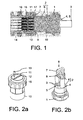
- einen Kontaktträger der Kabelanschlusseinrichtung gemäß dem bevorzugten Ausführungsbeispiel der Erfindung in einer Perspektivansicht,
- Fig. 2b
- eine Druckmutter und eine Aufnahmeeinrichtung der Kabelanschlusseinrichtung gemäß dem bevorzugten Ausführungsbeispiel der Erfindung in einer Perspektivansicht,
- Fig. 3a
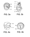
- den Kontaktträger der Kabelanschlusseinrichtung gemäß dem bevorzugten Ausführungsbeispiel der Erfindung in einer weiteren Perspektivansicht,
- Fig. 3b
- die Druckmutter und die Aufnahmeeinrichtung der Kabelanschlusseinrichtung gemäß dem bevorzugten Ausführungsbeispiel der Erfindung in einer weiteren Perspektivansicht,
- Fig. 4a
- einen Stecker der Kabelanschlusseinrichtung gemäß dem bevorzugten Ausführungsbeispiel der Erfindung in einer Perspektivansicht,
- Fig. 4b
- den Stecker der Kabelanschlusseinrichtung gemäß dem bevorzugten Ausführungsbeispiel der Erfindung in einer weiteren Perspektivansicht,
- Fig. 5a
- die Kabelanschlusseinrichtung gemäß dem bevorzugten Ausführungsbeispiel der Erfindung in einer Perspektivansicht, und
- Fig. 5b
- die Kabelanschlusseinrichtung gemäß dem bevorzugten Ausführungsbeispiel der Erfindung in einer weiteren Perspektivansicht.
- Fig. 1
- a cable connection device according to a preferred embodiment of the invention in a sectional view,
- Fig. 2a
- a contact carrier of the cable connection device according to the preferred embodiment of the invention in a perspective view,
- Fig. 2b
- a compression nut and a receiving device of the cable connection device according to the preferred embodiment of the invention in a perspective view,
- Fig. 3a
- the contact carrier of the cable connection device according to the preferred embodiment of the invention in a further perspective view,
- Fig. 3b
- the compression nut and the receiving device of the cable connection device according to the preferred embodiment of the invention in a further perspective view,
- Fig. 4a
- a plug of the cable connection device according to the preferred embodiment of the invention in a perspective view,
- Fig. 4b
- the plug of the cable connection device according to the preferred embodiment of the invention in a further perspective view,
- Fig. 5a
- the cable connection device according to the preferred embodiment of the invention in a perspective view, and
- Fig. 5b
- the cable connection device according to the preferred embodiment of the invention in a further perspective view.
Aus
Die Kabelanschlusseinrichtung weist eine Druckmutter 1 und eine Aufnahmeeinrichtung 2 auf. Ein mehradriges Kabel 3 ist durch die Druckmutter 1 durch eine Öffnung 4, 5 der Aufnahmeeinrichtung 2 in die Kabelanschlusseinrichtung eingeführt ist. Konkret ist das Kabel 3 durch eine erste Öffnung 4 in die Kabelanschlusseinrichtung hineingeführt und durch eine zweite Öffnung 5 aus der Kabelanschlusseinrichtung herausgeführt, wie aus
Die Aufnahmeeinrichtung 2 weist ferner eine Aderaufnahme 6 auf, wobei die Aufnahmeeinrichtung 2 und die Aderaufnahme 6 als separate Teile ausgeführt sind. In der Aderaufnahme 6 ist eine Ader 7 eines abgemantelten Abschnitts 8 des Kabels 3 radial zur Längsachse der Kabelanschlusseinrichtung positionierbar. Die Aderaufnahme 6 weist dazu eine Halbschale 9 auf, welche halbkreisförmig ausgestaltet ist, wie aus
Das Kabel 3 ist also durch die Druckmutter 1 sowie durch die erste Öffnung 4 der Aufnahmeeinrichtung 2 in die Kabelanschlusseinrichtung eingeführt, ein eingeführter Abschnitt 8 des Kabels 3 ist abgemantelt, wobei die Ader 7 des abgemantelten Abschnitts 8 des Kabels 3 radial zur Längsachse der Kabelanschlusseinrichtung auf der Aderaufnahme 6 positioniert sind, und das Kabel 3 ist im weiteren Verlauf durch die zweite Öffnung 5 der Aufnahmeeinrichtung 2 sowie durch die Druckmutter 1 aus der Kabelanschlusseinrichtung herausgeführt.The
Die Druckmutter 1 ist auf einen Kontaktträger 10 geschraubt, wie beispielsweise aus
Ein Pierce-Kontakt 11, vorliegend ausgeführt als spitze Kontaktschraube, ist zur elektrisch leitenden Kontaktierung einer Ader 7 vorgesehen. Dabei ist der Pierce-Kontakt 11 durch eine Öffnung 12 des Kontaktträgers 10 derart hindurchgeführt, dass der Pierce-Kontakt 11 gegenüberliegend zu dem Kabel 3 in die Kabelanschlusseinrichtung eingeführt ist. Zur elektrisch leitenden Kontaktierung der Ader 7 durchsticht der Pierce-Kontakt 11 eine Isolierung der A-der 7, wie in
Zum Befestigen der Kabelanschlusseinrichtung an einem Stecker 14 ist eine Überwurfmutter 15 vorgesehen ist. Der Stecker 14 ist beispielsweise an einer Wandung befestigbar und weist zum elektrisch leitenden Kontaktieren des Pierce-Kontakts 11 einen Kontaktstift 16 auf. Eine Dichtung 17, ausgeführt als O-Ring Dichtung, ist zwischen dem Stecker 14 und der Überwurfmutter 15 vorgesehen.To attach the cable connection device to a
Zum elektrisch leitenden Anschließen der Kabelanschlusseinrichtung an ein mehradriges Kabel 3 ist also wie beispielsweise folgend vorzugehen: Ein Abschnitt 8 des Kabels 3 ist abzumanteln, so dass die Adern 7 des abgemantelten Abschnitts 8 des Kabels 3 zum Vorschein kommen. Umlegen des Kabels 3, so dass der abgemantelte Abschnitt 8 des Kabels 3 in dem umgelegten Bereich des Kabels 3 zu liegen kommt, welches somit einen Halbkreis ausbildet. Das derart umgelegte Kabel 3 ist durch die Druckmutter 1 hindurchzuführen. Die Aderaufnahme 6 ist an dem abgemantelten Abschnitt 8 des Kabels 3 zu montieren, so dass die Adern 7 des abgemantelten Abschnitts 8 des Kabels 3 in der Aderaufnahme 6 zum Liegen kommen. Die Dichtungsteile sind zusammenzufügen, so dass die erste Öffnung 4 das Kabel 3 und die zweite Öffnung 5 das Kabel 3 umfassen. Die Druckmutter 1 ist derart auf den Kontaktträger 10 aufzuschrauben, dass die Druckmutter 1 die Aufnahmeeinrichtung 2 umgreift, so dass die Aderaufnahme 6 zum Kontaktträger 10 zeigt und durch Aufschrauben der Druckmutter 1 die Aufnahmeeinrichtung 2 zum Kontaktträger 10 gedrückt wird. Die Pierce-Kontakte 11 sind in den Kontaktträger 10 derart von der im Kabel 3 gegenüberliegenden Seite der Kabelanschlusseinrichtung einzubringen, dass ein jeder Pierce-Kontakt 11 je eine Ader 7 elektrisch leitend kontaktiert.For electrically conductive connection of the cable connection device to a
Die Kabelanschlusseinrichtung ist zum elektrisch leitenden Anschluss eines vorzugsweise mehradrigen Kabels 3 um ein elektrisches Gerät oder zum elektrischen Verbinden von zwei vorzugsweise mehradrigen Kabeln 3 verwendbar. Dabei kann ein Leiter der Ader 7 im Querschnitt ≥ 6 mm2, vorzugsweise ≥ 8 mm2 und ganz besonders bevorzugt ≥ 10 mm2 aufweisen.The cable connection device can be used for the electrically conductive connection of a preferably
Im Ergebnis wird eine Kabelanschlusseinrichtung bereitgestellt, mit der beispielsweise ein "laufendes" Kabel 3 und/oder ein Ende eines Kabels 3 an ein elektrisches Gerät anschließbar ist oder zwei Kabel 3 miteinander verbindbar sind, wobei die Kabelanschlusseinrichtung besonders einfach, und damit günstig, herstellbar ist, eine sehr kompakte Bauweise aufweist, eine parallele Leitungsführung von einem Abgriff, beispielsweise einem Kabelkanal, dem Kabelanschlusseinrichtung erlaubt, mit besonders hohen Strömen beaufschlagbar ist und/oder besonders einfach und sicher installierbar ist.As a result, a cable connection device is provided, with which, for example, a "running"
Claims (13)
- A cable connection device for the electrically conductive connection of a preferably multi-core cable (3), comprising a compression nut (1), a holding device (2) and a contact support (10), wherein
the cable can be passed through the compression nut (1) and through the opening in the holding device (2),
the holding device (2) has a core holder (6), wherein a core (7) of a sheathed portion (8) of the cable (4) can be positioned on the core holder (6) radially relative to the longitudinal axis of the cable connection device, and
the compression nut (1) can be screwed onto the contact support (10) in such a way that the compression nut (1) surrounds the holding device (2), the core holder (6) points toward the contact support (10), and the holder device (2) can be pressed against the contact support (10) by screwing on the compression nut (1),
characterised in that
the core holder (6) has a half-shell (9) for positioning the core (7). - The cable connection device according to Claim 1, wherein the holding device (2) has a first opening (4) and a second opening (5), the cable (3) can be passed through the first opening (4) into the cable connection device, and the cable (3) can be removed from the cable connection device through the second opening (5).
- The cable connection device according to Claim 1, wherein the holding device (2) has a first opening (4) and a second opening (5), the cable can be passed through the first opening (4) into the cable connection device, and the cable (3) can be fastened in a closure sleeve in the second opening (5).
- The cable connection device according to one of the preceding claims, wherein the holding device (2) is formed as a seal.
- The cable connection device according to one of Claims 2 to 4, wherein the holding device (2) is formed as a two-part seal in such a way that the first opening (4) and the second opening (5) are formed by joining together the seal parts.
- The cable connection device according to one of the preceding claims, wherein the core holder (6) and the core device (2) are formed as separate parts.
- The cable connection device according to one of the preceding claims, wherein a pierce contact (11) for electrically conductively contacting the core (7) is provided and the pierce contact (11) can be passed through an opening (12) in the contact support (10).
- The cable connection device according to Claim 7, wherein the pierce contact (11) is formed as a pointed contact screw and the contact screw has a female contact (13) at the end facing away from the pointed tip.
- The cable connection device according to one of the preceding claims, wherein a ring seal is provided between the compression nut (1) and the contact support (10).
- The cable connection device according to one of the preceding claims, wherein the contact support (10) has a cap nut (15) for fastening the cable connection device to a plug (14) .
- The cable connection device according to Claim 10, wherein the plug (14) can be fastened in a wall and the plug (14) has a contact pin (16) for electrically conductively contacting the pierce contact (11).
- The cable connection device according to one of the preceding claims, wherein the cable connection device can be used for a conductor cross section of the core (7) of ≥ 6 mm2, preferably ≥ 8 mm2 and most preferably ≥ 10 mm2.
- Use of a cable connection device according to one of the preceding claims for the electrically conductive connection of a preferably multi-core cable (3) to an electrical device or for the electrical connection of two preferably multi-core cables (3).
Applications Claiming Priority (2)
| Application Number | Priority Date | Filing Date | Title |
|---|---|---|---|
| DE102009018714A DE102009018714B3 (en) | 2009-04-27 | 2009-04-27 | Cable connecting device |
| PCT/EP2010/002571 WO2010124841A1 (en) | 2009-04-27 | 2010-04-27 | Cable connection device |
Publications (2)
| Publication Number | Publication Date |
|---|---|
| EP2425494A1 EP2425494A1 (en) | 2012-03-07 |
| EP2425494B1 true EP2425494B1 (en) | 2014-12-03 |
Family
ID=42371358
Family Applications (1)
| Application Number | Title | Priority Date | Filing Date |
|---|---|---|---|
| EP10722928.8A Not-in-force EP2425494B1 (en) | 2009-04-27 | 2010-04-27 | Cabel connection device |
Country Status (6)
| Country | Link |
|---|---|
| US (1) | US8672701B2 (en) |
| EP (1) | EP2425494B1 (en) |
| JP (1) | JP5392640B2 (en) |
| CN (1) | CN102414927B (en) |
| DE (1) | DE102009018714B3 (en) |
| WO (1) | WO2010124841A1 (en) |
Families Citing this family (10)
| Publication number | Priority date | Publication date | Assignee | Title |
|---|---|---|---|---|
| DE102009018714B3 (en) | 2009-04-27 | 2010-12-02 | Phoenix Contact Gmbh & Co. Kg | Cable connecting device |
| DE102012014617B3 (en) * | 2012-07-24 | 2013-05-08 | Hohenstein Vorrichtungsbau Und Spannsysteme Gmbh | Intelligent work clamping device is equipped power supply module, which has framed device module-part that supports fixed line connecting pins, where device module-part is stationary arranged with adapter plate |
| CN103682797A (en) * | 2013-11-30 | 2014-03-26 | 成都国科海博信息技术股份有限公司 | Waterproof plug with anti-dropping function |
| CN103682796A (en) * | 2013-11-30 | 2014-03-26 | 成都国科海博信息技术股份有限公司 | Waterproof plug suitable for field base station equipment |
| DE102016114166B3 (en) * | 2016-08-01 | 2017-12-14 | Kathrein-Werke Kg | Kink protection arrangement and method for mounting the kink protection |
| KR101871684B1 (en) * | 2016-10-12 | 2018-06-27 | 주식회사 대호테크 | Waveguide for EMP shielded |
| CN107248627A (en) * | 2017-05-22 | 2017-10-13 | 刘旭玲 | A kind of light current cable connecting device |
| CN112889190B (en) * | 2018-10-30 | 2023-03-03 | 上海诺基亚贝尔股份有限公司 | Power supply connector |
| DE102020125490B3 (en) * | 2020-09-30 | 2022-03-31 | Md Elektronik Gmbh | Method for assembling a multi-core cable and correspondingly assembled cable |
| CN114221201B (en) * | 2021-12-17 | 2024-06-11 | 广东电网有限责任公司 | A wire stripper |
Family Cites Families (11)
| Publication number | Priority date | Publication date | Assignee | Title |
|---|---|---|---|---|
| EP0542164B1 (en) * | 1991-11-14 | 1997-06-04 | Alcatel Components Limited | An electrical connector arrangement |
| AU667541B2 (en) * | 1992-07-03 | 1996-03-28 | Amphenol Corporation | Cord grip arrangement |
| IT1265145B1 (en) * | 1993-07-12 | 1996-10-31 | Cesare Gallone | CONNECTION DEVICE FOR ELECTRIC COMPONENTS |
| US5601448A (en) * | 1995-03-21 | 1997-02-11 | Sunskill Industries, Ltd. | Connector for lighting system and method |
| DE29801757U1 (en) * | 1998-02-03 | 1999-06-02 | Pflitsch GmbH & Co KG, 42499 Hückeswagen | Device for the sealed insertion of cables into an electrical connector |
| DE29806645U1 (en) * | 1998-04-11 | 1998-08-13 | Phoenix Contact Gmbh & Co., 32825 Blomberg | Cable connector |
| DE19836622C2 (en) * | 1998-08-13 | 2003-03-27 | Phoenix Contact Gmbh & Co | Cable connection or connection device |
| DE19924209B4 (en) * | 1999-05-27 | 2005-03-10 | Mennekes Elektrotechnik Gmbh & | plug-in device |
| DE10022547C2 (en) * | 2000-05-10 | 2003-10-02 | Phoenix Contact Gmbh & Co | Cable connection or connection device |
| DE20217501U1 (en) * | 2002-11-13 | 2003-02-06 | Anton Hummel Verwaltungs Gmbh, 79183 Waldkirch | cable connection |
| DE102009018714B3 (en) | 2009-04-27 | 2010-12-02 | Phoenix Contact Gmbh & Co. Kg | Cable connecting device |
-
2009
- 2009-04-27 DE DE102009018714A patent/DE102009018714B3/en not_active Expired - Fee Related
-
2010
- 2010-04-27 JP JP2012506408A patent/JP5392640B2/en not_active Expired - Fee Related
- 2010-04-27 CN CN201080018849.1A patent/CN102414927B/en not_active Expired - Fee Related
- 2010-04-27 US US13/266,454 patent/US8672701B2/en not_active Expired - Fee Related
- 2010-04-27 WO PCT/EP2010/002571 patent/WO2010124841A1/en not_active Ceased
- 2010-04-27 EP EP10722928.8A patent/EP2425494B1/en not_active Not-in-force
Also Published As
| Publication number | Publication date |
|---|---|
| US8672701B2 (en) | 2014-03-18 |
| EP2425494A1 (en) | 2012-03-07 |
| CN102414927B (en) | 2014-06-04 |
| WO2010124841A1 (en) | 2010-11-04 |
| US20120052717A1 (en) | 2012-03-01 |
| JP2012524957A (en) | 2012-10-18 |
| JP5392640B2 (en) | 2014-01-22 |
| DE102009018714B3 (en) | 2010-12-02 |
| CN102414927A (en) | 2012-04-11 |
Similar Documents
| Publication | Publication Date | Title |
|---|---|---|
| EP2425494B1 (en) | Cabel connection device | |
| EP2055535B1 (en) | Cable set, especially a high voltage cable set for a motor vehicle, and device to implement an electric cable and to connect a cable screen | |
| EP3342006B1 (en) | Electric cable subassembly | |
| EP2577804B1 (en) | Electric distributor device | |
| EP1129509B1 (en) | Connecting device | |
| EP3022806B1 (en) | Assembly comprising a housing and a device for electrically contact a shielding of an electric cable | |
| EP2993736B1 (en) | Electronic component | |
| DE29806645U1 (en) | Cable connector | |
| DE102013113878B4 (en) | Single-wire connector | |
| EP3261109B1 (en) | Fuse device | |
| WO2010091985A1 (en) | Plug-in connection device for connecting a cable to a connection housing | |
| EP1467441A2 (en) | Connector for quick connection in collet attachment technologie | |
| EP2658040B1 (en) | Plug | |
| DE102012214096A1 (en) | Connector and method of attaching a connector to one end of a cable | |
| EP1632009B1 (en) | Contact element and additional conduction chamber for a plug or socket produced according to insulating-piercing connecting technology | |
| DE19730435C1 (en) | Contact element with connector for flex conductor | |
| DE10323616A1 (en) | Rapid connection plug or socket connector in clamping jaws technology has contact partner with region in form of clamping jaws for accommodating stripped end of line of especially multi-strand cable | |
| DE102009038739B4 (en) | Arrangement for electrical connection, in particular electrical contact, of a multi-core coaxial cable with a circuit board, circuit arrangement and electrical device | |
| EP0505911A2 (en) | Device for an electric line | |
| EP3807959B1 (en) | Device for connecting high-voltage conductors | |
| EP4254683B1 (en) | Round plug connector and method for producing a round plug connector | |
| EP0700586B1 (en) | Electrical apparatus with device for electrically connecting two electric connecting cables to the apparatus | |
| EP4203197A1 (en) | Housing for receiving one or more conductor connection terminals and set formed therewith | |
| AT407594B (en) | CONNECTOR FOR ELECTRIC WHEEL MOTORS | |
| DE10111669C2 (en) | Cable connection or connection device |
Legal Events
| Date | Code | Title | Description |
|---|---|---|---|
| PUAI | Public reference made under article 153(3) epc to a published international application that has entered the european phase |
Free format text: ORIGINAL CODE: 0009012 |
|
| 17P | Request for examination filed |
Effective date: 20111123 |
|
| AK | Designated contracting states |
Kind code of ref document: A1 Designated state(s): AT BE BG CH CY CZ DE DK EE ES FI FR GB GR HR HU IE IS IT LI LT LU LV MC MK MT NL NO PL PT RO SE SI SK SM TR |
|
| DAX | Request for extension of the european patent (deleted) | ||
| GRAP | Despatch of communication of intention to grant a patent |
Free format text: ORIGINAL CODE: EPIDOSNIGR1 |
|
| INTG | Intention to grant announced |
Effective date: 20140707 |
|
| GRAS | Grant fee paid |
Free format text: ORIGINAL CODE: EPIDOSNIGR3 |
|
| GRAA | (expected) grant |
Free format text: ORIGINAL CODE: 0009210 |
|
| AK | Designated contracting states |
Kind code of ref document: B1 Designated state(s): AT BE BG CH CY CZ DE DK EE ES FI FR GB GR HR HU IE IS IT LI LT LU LV MC MK MT NL NO PL PT RO SE SI SK SM TR |
|
| REG | Reference to a national code |
Ref country code: GB Ref legal event code: FG4D Free format text: NOT ENGLISH |
|
| REG | Reference to a national code |
Ref country code: CH Ref legal event code: EP Ref country code: AT Ref legal event code: REF Ref document number: 699846 Country of ref document: AT Kind code of ref document: T Effective date: 20141215 |
|
| REG | Reference to a national code |
Ref country code: IE Ref legal event code: FG4D Free format text: LANGUAGE OF EP DOCUMENT: GERMAN |
|
| REG | Reference to a national code |
Ref country code: DE Ref legal event code: R096 Ref document number: 502010008403 Country of ref document: DE Effective date: 20150115 |
|
| REG | Reference to a national code |
Ref country code: NL Ref legal event code: VDEP Effective date: 20141203 |
|
| REG | Reference to a national code |
Ref country code: FR Ref legal event code: PLFP Year of fee payment: 6 |
|
| PG25 | Lapsed in a contracting state [announced via postgrant information from national office to epo] |
Ref country code: LT Free format text: LAPSE BECAUSE OF FAILURE TO SUBMIT A TRANSLATION OF THE DESCRIPTION OR TO PAY THE FEE WITHIN THE PRESCRIBED TIME-LIMIT Effective date: 20141203 Ref country code: NO Free format text: LAPSE BECAUSE OF FAILURE TO SUBMIT A TRANSLATION OF THE DESCRIPTION OR TO PAY THE FEE WITHIN THE PRESCRIBED TIME-LIMIT Effective date: 20150303 Ref country code: FI Free format text: LAPSE BECAUSE OF FAILURE TO SUBMIT A TRANSLATION OF THE DESCRIPTION OR TO PAY THE FEE WITHIN THE PRESCRIBED TIME-LIMIT Effective date: 20141203 Ref country code: NL Free format text: LAPSE BECAUSE OF FAILURE TO SUBMIT A TRANSLATION OF THE DESCRIPTION OR TO PAY THE FEE WITHIN THE PRESCRIBED TIME-LIMIT Effective date: 20141203 Ref country code: ES Free format text: LAPSE BECAUSE OF FAILURE TO SUBMIT A TRANSLATION OF THE DESCRIPTION OR TO PAY THE FEE WITHIN THE PRESCRIBED TIME-LIMIT Effective date: 20141203 |
|
| REG | Reference to a national code |
Ref country code: LT Ref legal event code: MG4D |
|
| PG25 | Lapsed in a contracting state [announced via postgrant information from national office to epo] |
Ref country code: HR Free format text: LAPSE BECAUSE OF FAILURE TO SUBMIT A TRANSLATION OF THE DESCRIPTION OR TO PAY THE FEE WITHIN THE PRESCRIBED TIME-LIMIT Effective date: 20141203 Ref country code: LV Free format text: LAPSE BECAUSE OF FAILURE TO SUBMIT A TRANSLATION OF THE DESCRIPTION OR TO PAY THE FEE WITHIN THE PRESCRIBED TIME-LIMIT Effective date: 20141203 Ref country code: GR Free format text: LAPSE BECAUSE OF FAILURE TO SUBMIT A TRANSLATION OF THE DESCRIPTION OR TO PAY THE FEE WITHIN THE PRESCRIBED TIME-LIMIT Effective date: 20150304 Ref country code: SE Free format text: LAPSE BECAUSE OF FAILURE TO SUBMIT A TRANSLATION OF THE DESCRIPTION OR TO PAY THE FEE WITHIN THE PRESCRIBED TIME-LIMIT Effective date: 20141203 Ref country code: CY Free format text: LAPSE BECAUSE OF FAILURE TO SUBMIT A TRANSLATION OF THE DESCRIPTION OR TO PAY THE FEE WITHIN THE PRESCRIBED TIME-LIMIT Effective date: 20141203 |
|
| PG25 | Lapsed in a contracting state [announced via postgrant information from national office to epo] |
Ref country code: CZ Free format text: LAPSE BECAUSE OF FAILURE TO SUBMIT A TRANSLATION OF THE DESCRIPTION OR TO PAY THE FEE WITHIN THE PRESCRIBED TIME-LIMIT Effective date: 20141203 Ref country code: SK Free format text: LAPSE BECAUSE OF FAILURE TO SUBMIT A TRANSLATION OF THE DESCRIPTION OR TO PAY THE FEE WITHIN THE PRESCRIBED TIME-LIMIT Effective date: 20141203 Ref country code: EE Free format text: LAPSE BECAUSE OF FAILURE TO SUBMIT A TRANSLATION OF THE DESCRIPTION OR TO PAY THE FEE WITHIN THE PRESCRIBED TIME-LIMIT Effective date: 20141203 Ref country code: PT Free format text: LAPSE BECAUSE OF FAILURE TO SUBMIT A TRANSLATION OF THE DESCRIPTION OR TO PAY THE FEE WITHIN THE PRESCRIBED TIME-LIMIT Effective date: 20150403 Ref country code: RO Free format text: LAPSE BECAUSE OF FAILURE TO SUBMIT A TRANSLATION OF THE DESCRIPTION OR TO PAY THE FEE WITHIN THE PRESCRIBED TIME-LIMIT Effective date: 20141203 |
|
| PG25 | Lapsed in a contracting state [announced via postgrant information from national office to epo] |
Ref country code: PL Free format text: LAPSE BECAUSE OF FAILURE TO SUBMIT A TRANSLATION OF THE DESCRIPTION OR TO PAY THE FEE WITHIN THE PRESCRIBED TIME-LIMIT Effective date: 20141203 Ref country code: IS Free format text: LAPSE BECAUSE OF FAILURE TO SUBMIT A TRANSLATION OF THE DESCRIPTION OR TO PAY THE FEE WITHIN THE PRESCRIBED TIME-LIMIT Effective date: 20150403 |
|
| PGFP | Annual fee paid to national office [announced via postgrant information from national office to epo] |
Ref country code: IT Payment date: 20150429 Year of fee payment: 6 Ref country code: FR Payment date: 20150424 Year of fee payment: 6 |
|
| REG | Reference to a national code |
Ref country code: DE Ref legal event code: R097 Ref document number: 502010008403 Country of ref document: DE |
|
| PLBE | No opposition filed within time limit |
Free format text: ORIGINAL CODE: 0009261 |
|
| STAA | Information on the status of an ep patent application or granted ep patent |
Free format text: STATUS: NO OPPOSITION FILED WITHIN TIME LIMIT |
|
| PG25 | Lapsed in a contracting state [announced via postgrant information from national office to epo] |
Ref country code: DK Free format text: LAPSE BECAUSE OF FAILURE TO SUBMIT A TRANSLATION OF THE DESCRIPTION OR TO PAY THE FEE WITHIN THE PRESCRIBED TIME-LIMIT Effective date: 20141203 |
|
| 26N | No opposition filed |
Effective date: 20150904 |
|
| PG25 | Lapsed in a contracting state [announced via postgrant information from national office to epo] |
Ref country code: MC Free format text: LAPSE BECAUSE OF FAILURE TO SUBMIT A TRANSLATION OF THE DESCRIPTION OR TO PAY THE FEE WITHIN THE PRESCRIBED TIME-LIMIT Effective date: 20141203 Ref country code: LU Free format text: LAPSE BECAUSE OF FAILURE TO SUBMIT A TRANSLATION OF THE DESCRIPTION OR TO PAY THE FEE WITHIN THE PRESCRIBED TIME-LIMIT Effective date: 20150427 |
|
| REG | Reference to a national code |
Ref country code: CH Ref legal event code: PL |
|
| GBPC | Gb: european patent ceased through non-payment of renewal fee |
Effective date: 20150427 |
|
| REG | Reference to a national code |
Ref country code: IE Ref legal event code: MM4A |
|
| PG25 | Lapsed in a contracting state [announced via postgrant information from national office to epo] |
Ref country code: CH Free format text: LAPSE BECAUSE OF NON-PAYMENT OF DUE FEES Effective date: 20150430 Ref country code: GB Free format text: LAPSE BECAUSE OF NON-PAYMENT OF DUE FEES Effective date: 20150427 Ref country code: LI Free format text: LAPSE BECAUSE OF NON-PAYMENT OF DUE FEES Effective date: 20150430 |
|
| PG25 | Lapsed in a contracting state [announced via postgrant information from national office to epo] |
Ref country code: SI Free format text: LAPSE BECAUSE OF FAILURE TO SUBMIT A TRANSLATION OF THE DESCRIPTION OR TO PAY THE FEE WITHIN THE PRESCRIBED TIME-LIMIT Effective date: 20141203 |
|
| PG25 | Lapsed in a contracting state [announced via postgrant information from national office to epo] |
Ref country code: IE Free format text: LAPSE BECAUSE OF NON-PAYMENT OF DUE FEES Effective date: 20150427 |
|
| REG | Reference to a national code |
Ref country code: AT Ref legal event code: MM01 Ref document number: 699846 Country of ref document: AT Kind code of ref document: T Effective date: 20150427 |
|
| PG25 | Lapsed in a contracting state [announced via postgrant information from national office to epo] |
Ref country code: AT Free format text: LAPSE BECAUSE OF NON-PAYMENT OF DUE FEES Effective date: 20150427 |
|
| PG25 | Lapsed in a contracting state [announced via postgrant information from national office to epo] |
Ref country code: MT Free format text: LAPSE BECAUSE OF FAILURE TO SUBMIT A TRANSLATION OF THE DESCRIPTION OR TO PAY THE FEE WITHIN THE PRESCRIBED TIME-LIMIT Effective date: 20141203 |
|
| REG | Reference to a national code |
Ref country code: FR Ref legal event code: ST Effective date: 20161230 |
|
| PG25 | Lapsed in a contracting state [announced via postgrant information from national office to epo] |
Ref country code: FR Free format text: LAPSE BECAUSE OF NON-PAYMENT OF DUE FEES Effective date: 20160502 |
|
| PG25 | Lapsed in a contracting state [announced via postgrant information from national office to epo] |
Ref country code: IT Free format text: LAPSE BECAUSE OF NON-PAYMENT OF DUE FEES Effective date: 20160427 |
|
| PG25 | Lapsed in a contracting state [announced via postgrant information from national office to epo] |
Ref country code: BG Free format text: LAPSE BECAUSE OF FAILURE TO SUBMIT A TRANSLATION OF THE DESCRIPTION OR TO PAY THE FEE WITHIN THE PRESCRIBED TIME-LIMIT Effective date: 20141203 Ref country code: SM Free format text: LAPSE BECAUSE OF FAILURE TO SUBMIT A TRANSLATION OF THE DESCRIPTION OR TO PAY THE FEE WITHIN THE PRESCRIBED TIME-LIMIT Effective date: 20141203 Ref country code: HU Free format text: LAPSE BECAUSE OF FAILURE TO SUBMIT A TRANSLATION OF THE DESCRIPTION OR TO PAY THE FEE WITHIN THE PRESCRIBED TIME-LIMIT; INVALID AB INITIO Effective date: 20100427 |
|
| PG25 | Lapsed in a contracting state [announced via postgrant information from national office to epo] |
Ref country code: BE Free format text: LAPSE BECAUSE OF NON-PAYMENT OF DUE FEES Effective date: 20150430 |
|
| PG25 | Lapsed in a contracting state [announced via postgrant information from national office to epo] |
Ref country code: TR Free format text: LAPSE BECAUSE OF FAILURE TO SUBMIT A TRANSLATION OF THE DESCRIPTION OR TO PAY THE FEE WITHIN THE PRESCRIBED TIME-LIMIT Effective date: 20141203 |
|
| PG25 | Lapsed in a contracting state [announced via postgrant information from national office to epo] |
Ref country code: MK Free format text: LAPSE BECAUSE OF FAILURE TO SUBMIT A TRANSLATION OF THE DESCRIPTION OR TO PAY THE FEE WITHIN THE PRESCRIBED TIME-LIMIT Effective date: 20141203 |
|
| REG | Reference to a national code |
Ref country code: DE Ref legal event code: R084 Ref document number: 502010008403 Country of ref document: DE |
|
| P01 | Opt-out of the competence of the unified patent court (upc) registered |
Effective date: 20230424 |
|
| PGFP | Annual fee paid to national office [announced via postgrant information from national office to epo] |
Ref country code: DE Payment date: 20230627 Year of fee payment: 14 |
|
| REG | Reference to a national code |
Ref country code: DE Ref legal event code: R119 Ref document number: 502010008403 Country of ref document: DE |
|
| PG25 | Lapsed in a contracting state [announced via postgrant information from national office to epo] |
Ref country code: DE Free format text: LAPSE BECAUSE OF NON-PAYMENT OF DUE FEES Effective date: 20241105 |
|
| PG25 | Lapsed in a contracting state [announced via postgrant information from national office to epo] |
Ref country code: DE Free format text: LAPSE BECAUSE OF NON-PAYMENT OF DUE FEES Effective date: 20241105 |