EP2425308B1 - Dispositif et procédé pour analyser un résidu afin de détecter des erreurs de comportement dans un système d'avion - Google Patents
Dispositif et procédé pour analyser un résidu afin de détecter des erreurs de comportement dans un système d'avion Download PDFInfo
- Publication number
- EP2425308B1 EP2425308B1 EP10717620.8A EP10717620A EP2425308B1 EP 2425308 B1 EP2425308 B1 EP 2425308B1 EP 10717620 A EP10717620 A EP 10717620A EP 2425308 B1 EP2425308 B1 EP 2425308B1
- Authority
- EP
- European Patent Office
- Prior art keywords
- variable
- model
- output
- disturbance
- residuum
- Prior art date
- Legal status (The legal status is an assumption and is not a legal conclusion. Google has not performed a legal analysis and makes no representation as to the accuracy of the status listed.)
- Not-in-force
Links
Images


Classifications
-
- G—PHYSICS
- G05—CONTROLLING; REGULATING
- G05B—CONTROL OR REGULATING SYSTEMS IN GENERAL; FUNCTIONAL ELEMENTS OF SUCH SYSTEMS; MONITORING OR TESTING ARRANGEMENTS FOR SUCH SYSTEMS OR ELEMENTS
- G05B23/00—Testing or monitoring of control systems or parts thereof
- G05B23/02—Electric testing or monitoring
- G05B23/0205—Electric testing or monitoring by means of a monitoring system capable of detecting and responding to faults
- G05B23/0218—Electric testing or monitoring by means of a monitoring system capable of detecting and responding to faults characterised by the fault detection method dealing with either existing or incipient faults
- G05B23/0243—Electric testing or monitoring by means of a monitoring system capable of detecting and responding to faults characterised by the fault detection method dealing with either existing or incipient faults model based detection method, e.g. first-principles knowledge model
- G05B23/0254—Electric testing or monitoring by means of a monitoring system capable of detecting and responding to faults characterised by the fault detection method dealing with either existing or incipient faults model based detection method, e.g. first-principles knowledge model based on a quantitative model, e.g. mathematical relationships between inputs and outputs; functions: observer, Kalman filter, residual calculation, Neural Networks
-
- G—PHYSICS
- G05—CONTROLLING; REGULATING
- G05B—CONTROL OR REGULATING SYSTEMS IN GENERAL; FUNCTIONAL ELEMENTS OF SUCH SYSTEMS; MONITORING OR TESTING ARRANGEMENTS FOR SUCH SYSTEMS OR ELEMENTS
- G05B17/00—Systems involving the use of models or simulators of said systems
-
- G—PHYSICS
- G05—CONTROLLING; REGULATING
- G05B—CONTROL OR REGULATING SYSTEMS IN GENERAL; FUNCTIONAL ELEMENTS OF SUCH SYSTEMS; MONITORING OR TESTING ARRANGEMENTS FOR SUCH SYSTEMS OR ELEMENTS
- G05B23/00—Testing or monitoring of control systems or parts thereof
- G05B23/02—Electric testing or monitoring
- G05B23/0205—Electric testing or monitoring by means of a monitoring system capable of detecting and responding to faults
- G05B23/0218—Electric testing or monitoring by means of a monitoring system capable of detecting and responding to faults characterised by the fault detection method dealing with either existing or incipient faults
- G05B23/0224—Process history based detection method, e.g. whereby history implies the availability of large amounts of data
- G05B23/0227—Qualitative history assessment, whereby the type of data acted upon, e.g. waveforms, images or patterns, is not relevant, e.g. rule based assessment; if-then decisions
- G05B23/0235—Qualitative history assessment, whereby the type of data acted upon, e.g. waveforms, images or patterns, is not relevant, e.g. rule based assessment; if-then decisions based on a comparison with predetermined threshold or range, e.g. "classical methods", carried out during normal operation; threshold adaptation or choice; when or how to compare with the threshold
-
- G—PHYSICS
- G06—COMPUTING OR CALCULATING; COUNTING
- G06F—ELECTRIC DIGITAL DATA PROCESSING
- G06F17/00—Digital computing or data processing equipment or methods, specially adapted for specific functions
- G06F17/10—Complex mathematical operations
-
- G—PHYSICS
- G06—COMPUTING OR CALCULATING; COUNTING
- G06F—ELECTRIC DIGITAL DATA PROCESSING
- G06F17/00—Digital computing or data processing equipment or methods, specially adapted for specific functions
- G06F17/10—Complex mathematical operations
- G06F17/11—Complex mathematical operations for solving equations, e.g. nonlinear equations, general mathematical optimization problems
-
- G—PHYSICS
- G06—COMPUTING OR CALCULATING; COUNTING
- G06F—ELECTRIC DIGITAL DATA PROCESSING
- G06F30/00—Computer-aided design [CAD]
- G06F30/10—Geometric CAD
- G06F30/15—Vehicle, aircraft or watercraft design
-
- G—PHYSICS
- G06—COMPUTING OR CALCULATING; COUNTING
- G06F—ELECTRIC DIGITAL DATA PROCESSING
- G06F30/00—Computer-aided design [CAD]
- G06F30/10—Geometric CAD
- G06F30/17—Mechanical parametric or variational design
Definitions
- the present invention relates to a device and a method for generating a residual for detecting erroneous transients, drifts or oscillations in the system behavior of a system of an aircraft.
- the technical field of the invention relates to the evaluation of a generated residual for the detection of system errors, in particular of erroneous transients, drifts or oscillations, in the system behavior of a system of an aircraft, for example an electro-hydraulic rudder control system.
- OFC scenarios includes errors in components of data processing and signal processing, software errors, mechanical defects, for example in the servo valve assembly, or failures of individual electronic components on the lowest circuit level, for example in the voltage-current converter.
- the approach of a detailed, non-linear or a simplified linear parallel model is provided, which in the Fig. 2 of the US 2007/0124038 A1 is shown.
- the reference numeral 19 of the Fig. 2 provided unit the parallel model, which includes the detailed, non-linear mapping of the real system dynamics or a simplified linear description.
- the time-varying guide specification - designated by the reference numeral 20 - provided for the Aktuatorregelnik, which is impressed by the flight control computer.
- the only output signal of the parallel model 19 is designated by the reference numeral 29 and describes the estimated time-varying Aktuatorkolbenposition.
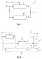
- FIG. 1 a schematic block diagram of a conventional device V for generating a residual r.
- the conventional device V corresponds to Fig. 1 a generalized presentation of the Fig. 4 of the US 2007/0124038 A1 In order to better represent the disadvantages of the prior art.
- the reference numeral z denotes a disturbance that maps external disturbances to the system S.
- the system S has the command variable w as an input variable and provides the system output variable y on the output side.
- the system S is a real electro-hydraulic rudder servo system and the system output y corresponds to a measured displacement of the actuator vault of the rudder servo system.
- a system model SM is arranged parallel to the system S.
- the estimation method described above essentially consists of the parallel system model or process model, which in the form of a mathematical description best approximates the initial values of the process or system and its parameterization.
- the identical input signal for the system S, the command variable or command value w is the only input signal of the system model SM.
- the estimated system output ⁇ of the system model SM results.
- the residual r the difference between the time-varying system output signal y and the estimated system output signal ⁇ of the system model SM formed.
- the residual r is used in case of exceeding a predefined threshold for identifying a system error.
- the process or the system S changes as a result of changes in parameters or boundary conditions, for example airspeed, altitude, setting and sliding angles, temperature, properties of the hydraulic system Medium of the actuator and the like, during operation or flight. These changes affect the response behavior of the system S and thus the momentum of the system S. They are not mapped by the parallel process model or system model SM.
- the evaluation module 23 compares the residual 24 with a predefined threshold value and counts every exceeding of this threshold value. After a predetermined number of counted overshoots of the predetermined threshold, an oscillatory error condition is detected and an output 26 is set to a positive logic value to indicate this error.
- this consists of a serial combination of a frequency-selective filter bank, unit numbered 27, and a downstream comparator stage, unit numbered 25, for each individual frequency band of the Residuums 24.
- the frequency-selective filter bank 27 consists from a parallel connection of bandpass filters for the spectral separation of the residual 24 into predetermined frequency bands.
- reference numeral 28 denotes a vector of the spectral components of the residual 24 in the frequency bands determined by the frequency-selective filter bank 27.
- the comparator bank 25 in each case comprises a separate channel for each component of the vector 28, in which the respective component is compared with a predefined threshold value.
- the case of exceeding is noted by means of a counter. If the number of counted overflows of a channel exceeds a predetermined limit, the oscillatory error is detected and indicated by means of the output signal 28.
- the detection thresholds must be increased accordingly and, if necessary, the number of required acknowledgment cycles must be increased. This has for the detection of continuous vibrations due to system errors a greatly reduced sensitivity and further increased detection time of the evaluation module result. This is particularly true of system errors in which an oscillating component is superimposed with a nominal low frequency system output signal.
- the EP 1 420 153 A2 discloses another apparatus and method for generating residuals for detecting system errors.
- this object is achieved by a device having the features of patent claim 1 and / or an aircraft having the features of patent claim 7 and / or by a method having the features of patent claim 8 and / or a computer program product having the features of patent claim 10.
- the respective means, the first to fourth means can be implemented by hardware or software technology.
- the respective means can be designed as a device, for example as a computer or microprocessor, as a device or as part of a system, for example as a computer system.
- the respective means may be designed as a computer program product, as a function, as a routine, as part of a program code or as an executable object.
- a computer program product which causes a program-controlled device to carry out a method for generating residuals as described above for detecting erroneous transients, drifts or oscillations in the system behavior of a system of an aircraft.
- the first to fourth means in particular form a Störbeobachter unit or a Störbeobachter.
- the observer invention enforces a follow-up behavior of the system model with respect to the estimated system output, for example, the piston position of the rudder servo system. This is achieved by returning the residual to the internal states of the system model via the observer feedback.
- the disturbance model is set up parallel to the observer feedback.
- the approximated or estimated disturbance which according to the invention is mapped as a disturbance model size, is also attributed to the internal states of the system model.
- an indirect effect of the external disturbances of the system in the estimated system output variable or in the disturbance observer output is additionally mapped.
- An advantage of the present invention is the robust generation of a residual by means of which the presence of an error, in particular in the form of erroneous transients, drift, creep or oscillations in a system of an aircraft is detectable.
- the evaluation is then carried out by comparing the residual with a predetermined threshold.
- external disturbances that have an effect on the process or the system are represented by the interference observer according to the invention as an approximation.
- Such external disturbances or process disturbances result essentially from air forces acting on the driven footprint during operation, particularly as transient disturbances from one-time events such as gusts, harmonic disturbances by periodic vortex shedding or effects from the flexibility of the surrounding structure or from stochastic disturbances such as turbulence , and according to the invention do not lead to a significant effect on the residuum.
- variable parameters are the airspeed, the altitude, the pitch and roll angle, the temperature, the hydraulic medium characteristics of the actuator, and the like. These changes affect the response and the momentum of the system. They are also imaged by the interferer according to the invention on the forced follow-up behavior and are therefore not visible in the residuum.
- the system model can be reduced by these elements.
- the measurable quantities are provided to the observer as additional input variables. They advantageously increase the quality of the estimated system output of the observer and further minimize the residual.
- the reduced observer can in this case be reduced to the subprocess or to the subsystem of the not directly measurable and / or reliable dynamic effects.
- the reduction of the complete observer to one in the fixed System equations integrated, reduced observer leads to a further increase in robustness and thus to accelerate the runtime characteristics of the proposed method.
- Fig. 2 shows a schematic block diagram of a first embodiment of a device E for Residuenaüs Edinburgh a Residuums r for detecting system errors in the system behavior of a system S of an aircraft.
- the system S receives a time-variable reference variable w and an external disturbance-measuring disturbance variable z.
- the system S provides a system output variable y on the output side.
- the device E for residual evaluation has at least one device V for residual generation of the residual r, a comparator unit KE, a first unit E1, a second unit E2 and a third unit E3.
- the device V is suitable for the residual generation of the residual r, wherein the device V generates the residual r at least as a function of the reference variable w and the system output variable y.
- the device V is, for example, according to one of the embodiments of FIGS. 4 or 5 educated.
- the comparator unit KE provides an evaluation result b by means of a comparison of the residual r with a threshold value s provided.
- the units E1 to E3 are provided.
- the first unit E1 is set up to provide a constant threshold value s0.
- the second unit E2 is set up to provide an adaptive threshold value s1 at least as a function of the time-variable reference variable w.
- the third unit E3 is set up to provide the threshold value s by means of a combination of the constant threshold component s0 with the adaptive threshold component s1.
- the third unit E3 adds the constant threshold value S0 to the adaptive threshold value s1 to form the threshold value s.
- the comparator unit KE sets the evaluation result b for indicating a system error to a positive logical value, if the provided residual r is greater than the provided threshold value s.
- the evaluation result b can also be embodied as a signal, for example as a continuous signal, which is set up to indicate the two possible states (r> s and r ⁇ s).
- Fig. 3 shows a second embodiment of an inventive device E for Residuenaustechnisch a Residuums r for detecting system errors in the system behavior of a system S of an aircraft.
- the second embodiment according to Fig. 3 includes all features of the first embodiment according to Fig. 2 which are therefore not shown again to avoid repetition.
- the first unit E1 is set up to provide the constant threshold value s0 as a function of an expected, inherent measurement noise mr of the system S.
- the first unit E1 preferably sets the constant threshold value s0 to a minimum value.
- the second unit E2 is set up to provide the adaptive threshold value s1 as a function of the time-variable reference variable w, at least one provided measured variable mg of the system S and / or a state variable zg estimated by means of a system model SM of the device V.
- the device E preferably has a fourth unit E4 which is set up to activate the comparator unit KE after a predetermined confirmation time has elapsed.
- the fourth unit E4 preferably controls the comparator unit KE by means of an activation signal a.
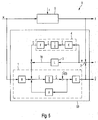
- FIG. 4 a schematic block diagram of an embodiment of the inventive device V for Residuengentechnik for detecting system errors, in particular of erroneous transients, drift or oscillations, shown in the system behavior of a system S of an aircraft.
- the residual generation device V for detecting erroneous transients, drifts or oscillations in the system behavior of a system S of an aircraft has a first means 1, a second means 2, a third means 3 and a fourth means 4.
- the first to fourth means 1-4 form a Störbeobachter unit SB.
- the system S receives a guidance input w and a disturbance variable z, which maps external disturbances onto the system S.
- the system provides a system output position y on the output side.
- the system S is, for example, an electro-hydraulic rudder control system of the aircraft, in which case the system output variable y is a measured displacement of the actuator piston of the position-controlled rudder control system S.
- the first means 1 has a system model SM for mapping the system S to be monitored.
- the first means 1 receives on the input side the reference variable w, an observer feedback variable b and a disturbance model variable ⁇ . Depending on this, the first means 1 provides on the output side an estimated system output ⁇ ( Fig. 4 ).
- the second means 2 is arranged to form a residue r from the difference between the system output y and the estimated system output ⁇ .
- the second means 2 is designed, for example, as a subtractor.
- the third means 3 is designed as an observer feedback L.
- the third means 3 receives on the input side the residual r and, depending on the received residual r, provides on the output side the observer feedback quantity bg for dynamic correction of the system model SM such that the estimated system output ⁇ follows the system output y.
- the fourth means 4 is equipped with a disturbance model ZM, which receives the residue r on the input side and, depending on the output side, provides the disturbance model variable ⁇ for mapping the effects or effects of the external disturbances onto the system model SM.
- the observer feedback L is set, in particular for the dynamic correction of the internal states of the system model SM, such that the estimated system output ⁇ follows the system output y, a decay of an initial disturbance and a follow-up behavior of the external disturbances due to a weighting of the residuals r and a return to the system model SM is provided.
- Fig. 5 shows a second embodiment of a device according to the invention V for Residuengener mich a Residuums r for detecting system errors, in particular of erroneous transients, drift or oscillations in the system behavior of a system S of an aircraft.
- the second embodiment according to Fig. 5 includes all features of the first embodiment according to Fig. 4 which are therefore not shown again to avoid repetition.
- the observer unit SB has an observer feedback matrix L for the formation of the observer feedback.
- the coefficients of the observer feedback matrix L are determined via a state controller design.
- the state controller design is formed, for example, by a pole specifier, an optimal regulator design, a robust ripple design design method, linear quadratic estimators (LQE), or nonlinear approaches.
- the disturbance model size ⁇ or estimated disturbance ⁇ is embodied as a dynamic disturbance model variable ⁇ , which is formed by means of a linear combination of artificial system states.
- the dynamic interference model variable ⁇ is preferably determined by means of a linear combination of an adjustment matrix K, an integrator 1 s and a disturbance variable matrix F formed.
- the control matrix K receives the residual r and the disturbance variable matrix F provides the disturbance model variable ⁇ on the output side.
- the integrator 1 s is arranged between the control matrix K and the disturbance variable matrix F.
- x denotes the system states of the linear system model SM, which can be obtained by integration by means of the integrator 1 s from temporal changes of the system states x ⁇ ⁇ result.
- Fig. 6 shows a schematic flow diagram of an embodiment of a method for residual evaluation of a residual r for detecting system errors in the system behavior of a system S of an aircraft.
- a residual r is generated at least as a function of the reference variable w and the system output variable y.
- a constant threshold value s0 is provided.
- An adaptive threshold value s1 is provided at least as a function of the time-variable reference variable w.
- a threshold value s is provided by means of a combination, in particular by means of an addition, of the constant threshold value s0 with the adaptive threshold value s1.
- the residual r is compared with the provided threshold value s for providing an evaluation result b. If the residual r is above the provided threshold value s, a system error of the system S is detected.
- Fig. 7 shows a schematic flow diagram of an embodiment of the inventive method for Residuengener ist a Residuums r for detecting system errors, especially of erroneous transients, drift or oscillations, in the system behavior of a system S of an aircraft, which receives a reference variable w and an external interference imaged disturbance z and the output side provides a system output y.
- the method according to the invention will be described below with reference to the block diagram in FIG Fig. 7 with reference to the block diagram in Fig. 4 described.
- the embodiment of the method according to the invention Fig. 7 has the following method steps S1 to S4:
- a system model SM for mapping the system S to be monitored is provided.
- the system model SM receives on the input side the reference variable w, an observer feedback quantity bg and a disturbance model variable z. Depending on this, the system model SM provides an estimated system output variable ⁇ on the output side.
- a residual r is made up of the difference between the system output y and the estimated system output ⁇ .
- An observer feedback loop L which receives the residue r on the input side and, depending on the output side, provides the observer feedback variable bg for the dynamic correction of the system model SM in such a way that the estimated system output ⁇ follows the system output variable y.
- An interference model ZM is provided which receives the residual r on the input side and, depending on the output side, provides the interference model variable ⁇ for mapping the effects or effects of the external interference onto the system model SM.
- the quantity of the estimated system variables preferably becomes in the system model SM is reduced by this extended measured variable and this further measured variable is fed directly to the system model SM as a further input variable.
- FIGS. 8 to 12 show schematic timing diagrams to illustrate the invention Residuenaustechnisch a Residuums r for detecting system errors FC in the system behavior of a system S of an aircraft.
- a rudder servo system as a system S is based on a first actuator - designated by the displacement of the actuator piston of the first actuator as the system output signal y1 - and a redundant second actuator - designated by the displacement of the actuator piston of the second actuator as the system output signal y2 ,
- FIG. 8 shows the time course of the system output signals y1 and y2.
- FIG. 9 shows the time course of the disorder z.
- FIG. 10 shows the time course of the residual r and the inventive threshold s.
- Figures 11 show the time course of the evaluation result b and the time course of a drive signal msv, which is generated as a function of the evaluation result b for selecting the actuator 1 or 2.
- FIG. 8 shows FIG. 8 the time course of the system output signals y1 and y2.
- the system output signals y1 and y2 increase significantly according to the guidance input w.
- FIG. 9 the time course of the disturbance z, which corresponds to a force with which the actuated by the actuator 1 or 2 footprint of the aircraft is loaded. This force is also referred to as aerodynamic load or air load.
- FIG. 10 the time course of the residual r and the inventive threshold s.
- the threshold value s is adjusted as a function of the guidance input w, ie the threshold value s is adjusted as a function of the jumping of the guidance input w and will therefore jump itself (see Fig. 10a )
- the threshold value s is adjusted as a function of the jumping of the guidance input w and will therefore jump itself (see Fig. 10a )
- FIG. 12 is at the end of a confirmation time BZ, which is for example 2 s, a drive signal msv from 1 to 0 switch over. This switching indicates that switching is made from the first actuator to the second actuator.
- a confirmation time BZ which is for example 2 s
- msv a drive signal from 1 to 0 switch over.
Landscapes
- Physics & Mathematics (AREA)
- Engineering & Computer Science (AREA)
- Artificial Intelligence (AREA)
- Evolutionary Computation (AREA)
- Mathematical Physics (AREA)
- General Physics & Mathematics (AREA)
- Automation & Control Theory (AREA)
- Feedback Control In General (AREA)
- Measurement Of Mechanical Vibrations Or Ultrasonic Waves (AREA)
- Testing And Monitoring For Control Systems (AREA)
- Traffic Control Systems (AREA)
- Electric Propulsion And Braking For Vehicles (AREA)
Claims (10)
- Dispositif (V) destiné à générer un résidu (r) permettant de détecter des transitoires défectueux, des dérives ou des oscillations dans le comportement de système d'un système (S) d'un aéronef, lequel système reçoit côté entrée une instruction de gestion (w) et une grandeur perturbatrice (z) reproduisant des perturbations externes, et fournit côté sortie une grandeur de sortie (y) du système, comprenant :a) un premier moyen (1) comprenant un modèle de système (SM) pour la reproduction du système (S) à surveiller, lequel reçoit côté entrée l'instruction de gestion (w), une grandeur de retour d'observateur (bg) et une grandeur de modèle de perturbation (ẑ) et, en fonction de cela, fournit côté sortie une grandeur de sortie estimée (ŷ) du système ;b) un deuxième moyen (2) pour la formation d'un résidu (r) à partir de la différence entre la grandeur de sortie (y) du système et la grandeur de sortie estimée (ŷ) du système ;c) un troisième moyen (3) comprenant un retour d'observateur, lequel reçoit le résidu (r) côté entrée et, en fonction de cela, fournit côté sortie la grandeur de retour d'observateur (bg) pour la correction dynamique du modèle de système (SM) de manière à ce que la grandeur de sortie estimée (ŷ) du système succède à la grandeur de sortie du système (y) ; etd) un quatrième moyen (4) comprenant un modèle de perturbation (ZM), lequel reçoit le résidu (r) côté entrée et, en fonction de cela, fournit côté sortie la grandeur de modèle de perturbation (ẑ) pour la reproduction des effets des perturbations externes sur le modèle de système (SM), dans lequel la grandeur de modèle de perturbation (ẑ) est réalisée comme une grandeur de modèle de perturbation dynamique (z), laquelle est formée au moyen d'une combinaison linéaire d'une matrice de régulation (K), d'un intégrateur

- Dispositif selon la revendication 1, caractérisé en ce que le système (S) est un système de réglage de gouverne électrohydraulique de l'aéronef.
- Dispositif selon la revendication 2, caractérisé en ce que la grandeur de sortie du système (y) est un décalage mesuré du piston d'actionneur du système de régulation de gouverne (S) réglé en position ou la position mesurée du plan réglable de l'aéronef.
- Dispositif selon l'une quelconque des revendications 1 à 3, caractérisé en ce
que le retour d'observateur pour la correction dynamique des états intérieurs du modèle de système (SM) est réglé de manière à ce que la grandeur de sortie estimée (ŷ) du système succède à la grandeur de sortie du système (y), dans lequel un évanouissement d'une perturbation initiale et un comportement consécutif des perturbations externes sont fournis par une pondération des résidus (r) et un retour sur le modèle de système (SM). - Dispositif selon la revendication 4, caractérisé en ce que le retour d'observateur comprend une matrice de retour d'observateur (L).
- Dispositif selon la revendication 5, caractérisé en ce que des coefficients de la matrice de retour d'observateur (L) sont déterminés par l'intermédiaire d'un projet de régleur d'état, notamment par l'intermédiaire d'une indication de pôle, d'un projet de régleur optimal, d'un procédé de projet pour la conception de retours robustes, d'évaluateurs linéaires carrés (LQE) ou d'approches non linéaires.
- Aéronef comprenant un ou plusieurs dispositifs (V) selon l'une quelconque des revendications 1 à 6.
- Procédé destiné à générer un résidu (r) permettant de détecter des transitoires défectueux, des dérives ou des oscillations dans le comportement de système d'un système (S) d'un aéronef, lequel système reçoit côté entrée une instruction de gestion (w) et une grandeur perturbatrice (z) reproduisant des perturbations externes, et fournit côté sortie une grandeur de sortie (y) du système, comprenant les étapes :a) mise à disposition d'un modèle de système (SM) pour la reproduction du système (S) à surveiller, lequel reçoit côté entrée l'instruction de gestion (w), une grandeur de retour d'observateur (bg) et une grandeur de modèle de perturbation (ẑ) et, en fonction de cela, fournit côté sortie une grandeur de sortie estimée (ŷ) du système ;b) formation d'un résidu (r) à partir de la différence entre la grandeur de sortie du système (y) et la grandeur de sortie estimée ((ŷ) du système ;c) mise à disposition d'un retour d'observateur, lequel reçoit le résidu (r) côté entrée et, en fonction de cela, fournit côté sortie la grandeur de retour d'observateur (bg) pour la correction dynamique du modèle de système (SM) de manière à ce que la grandeur de sortie estimée (ŷ) du système succède à la grandeur de sortie (y) du système ; etd) mise à disposition d'un modèle de perturbation (ZM), lequel reçoit le résidu (r) côté entrée et, en fonction de cela, fournit côté sortie la grandeur de modèle de perturbation (ẑ) pour la reproduction des effets des perturbations externes sur le modèle de système (SM), dans lequel la grandeur de modèle de perturbation (ẑ) est réalisée comme une grandeur de modèle de perturbation dynamique (z), laquelle est formée au moyen d'une combinaison linéaire d'une matrice de régulation (K), d'un intégrateur

- Procédé selon revendication 8, caractérisé en ce que lorsqu'une grandeur de mesure supplémentaire du système (S) est disponible, le modèle de système (SM) est diminué de cette grandeur de mesure supplémentaire et cette grandeur de mesure supplémentaire est amenée au modèle de système (SM) en tant que grandeur d'entrée supplémentaire.
- Produit de programme informatique, lequel entraîne la réalisation d'un procédé selon la revendication 8 ou 9 sur un dispositif commandé par programme.
Priority Applications (1)
| Application Number | Priority Date | Filing Date | Title |
|---|---|---|---|
| EP12191846.0A EP2557467A3 (fr) | 2009-04-28 | 2010-04-28 | Dispositif et procédé d'évaluation de résidus d'une matière résiduelle pour la détection d'erreurs système dans le comportement du système d'un avion |
Applications Claiming Priority (3)
| Application Number | Priority Date | Filing Date | Title |
|---|---|---|---|
| US17323909P | 2009-04-28 | 2009-04-28 | |
| DE102009002682A DE102009002682B4 (de) | 2009-04-28 | 2009-04-28 | Einrichtung und Verfahren zur Residuenauswertung eines Residuums zur Erkennung von Systemfehlern im Systemverhalten eines Systems eines Flugzeugs |
| PCT/EP2010/055664 WO2010125080A2 (fr) | 2009-04-28 | 2010-04-28 | Dispositif et procédé pour analyser un résidu afin de détecter des erreurs de comportement dans un système d'avion |
Related Child Applications (1)
| Application Number | Title | Priority Date | Filing Date |
|---|---|---|---|
| EP12191846.0A Division-Into EP2557467A3 (fr) | 2009-04-28 | 2010-04-28 | Dispositif et procédé d'évaluation de résidus d'une matière résiduelle pour la détection d'erreurs système dans le comportement du système d'un avion |
Publications (2)
| Publication Number | Publication Date |
|---|---|
| EP2425308A2 EP2425308A2 (fr) | 2012-03-07 |
| EP2425308B1 true EP2425308B1 (fr) | 2016-06-15 |
Family
ID=42972759
Family Applications (2)
| Application Number | Title | Priority Date | Filing Date |
|---|---|---|---|
| EP12191846.0A Withdrawn EP2557467A3 (fr) | 2009-04-28 | 2010-04-28 | Dispositif et procédé d'évaluation de résidus d'une matière résiduelle pour la détection d'erreurs système dans le comportement du système d'un avion |
| EP10717620.8A Not-in-force EP2425308B1 (fr) | 2009-04-28 | 2010-04-28 | Dispositif et procédé pour analyser un résidu afin de détecter des erreurs de comportement dans un système d'avion |
Family Applications Before (1)
| Application Number | Title | Priority Date | Filing Date |
|---|---|---|---|
| EP12191846.0A Withdrawn EP2557467A3 (fr) | 2009-04-28 | 2010-04-28 | Dispositif et procédé d'évaluation de résidus d'une matière résiduelle pour la détection d'erreurs système dans le comportement du système d'un avion |
Country Status (6)
| Country | Link |
|---|---|
| US (1) | US9535419B2 (fr) |
| EP (2) | EP2557467A3 (fr) |
| CN (1) | CN102483626B (fr) |
| DE (2) | DE102009002682B4 (fr) |
| RU (1) | RU2501063C2 (fr) |
| WO (1) | WO2010125080A2 (fr) |
Families Citing this family (18)
| Publication number | Priority date | Publication date | Assignee | Title |
|---|---|---|---|---|
| FR2978585B1 (fr) | 2011-07-26 | 2013-08-16 | Airbus Operations Sas | Procede et dispositif d'estimation automatique d'un vecteur parametre de vol d'un aeronef, ainsi que methode et ensemble de detection d'une panne affectant un tel vecteur |
| CN102385311B (zh) * | 2011-09-15 | 2013-08-07 | 江苏科技大学 | 电液线速度数字伺服系统的控制方法 |
| FR2982239B1 (fr) * | 2011-11-08 | 2014-05-09 | Airbus Operations Sas | Procede et dispositif de detection du blocage d'une gouverne d'aeronef. |
| CN102929293B (zh) * | 2012-11-02 | 2015-09-23 | 江苏科技大学 | 一种用于机械装备的数字随动装置及控制方法 |
| CN103047230B (zh) * | 2013-01-15 | 2015-04-22 | 太原科技大学 | 一种提高电液伺服系统动态负载刚度的控制方法 |
| FR3019295B1 (fr) * | 2014-03-27 | 2016-03-18 | Snecma | Procede d'estimation du caractere normal ou non d'une valeur mesuree d'un parametre physique d'un moteur d'aeronef |
| CN104458297B (zh) * | 2014-11-12 | 2017-10-10 | 南京航空航天大学 | 基于非线性随机模型的列车悬架系统传感器故障检测方法 |
| CN104850889B (zh) * | 2014-11-19 | 2017-02-22 | 北京航空航天大学 | 一种飞机旋转作动器驱动装置自适应故障检测、隔离与健康评估的方法 |
| CN104390776B (zh) * | 2014-12-10 | 2016-11-16 | 北京航空航天大学 | 一种多余度副翼作动器故障检测、诊断与性能评估方法 |
| FR3042612B1 (fr) * | 2015-10-14 | 2020-12-11 | Airbus Operations Sas | Procede et dispositif de detection de pannes oscillatoires dans une chaine d'asservissement en position d'une gouverne d'aeronef. |
| CN109191401A (zh) * | 2018-08-30 | 2019-01-11 | 西安电子科技大学 | 一种基于并联残差网络模型的红外图像非均匀性校正方法 |
| CN109670145A (zh) * | 2018-12-12 | 2019-04-23 | 中国航空工业集团公司上海航空测控技术研究所 | 基于观测器的直升机主减速器振动特征阈值设置方法 |
| EP3875927B1 (fr) * | 2020-03-02 | 2025-04-30 | Nabtesco Corporation | Dispositif, procédé et programme de détection de vibrations d'aéronef |
| CN114996706B (zh) * | 2022-06-22 | 2023-04-04 | 燕山大学 | 基于未知输入观测器的智能交通虚假数据攻击检测方法 |
| CN115981265B (zh) * | 2022-07-06 | 2024-08-02 | 北京航空航天大学 | 基于扩张观测器的舰载机故障在线检测方法 |
| CN115685955B (zh) * | 2022-09-28 | 2023-05-16 | 南通大学 | 一种空气处理单元的故障检测和反馈控制集成设计方法 |
| CN119414818B (zh) * | 2024-11-01 | 2025-08-12 | 南京工业大学 | 基于干扰解耦观测器的反馈控制系统故障检测方法 |
| CN121028563B (zh) * | 2025-10-14 | 2026-01-30 | 天目山实验室 | 一种航空涡轮发动机的异常运行状态自主重构方法 |
Family Cites Families (19)
| Publication number | Priority date | Publication date | Assignee | Title |
|---|---|---|---|---|
| US5319296A (en) * | 1991-11-04 | 1994-06-07 | Boeing Commercial Airplane Group | Oscillatory servo-valve monitor |
| US7058617B1 (en) * | 1996-05-06 | 2006-06-06 | Pavilion Technologies, Inc. | Method and apparatus for training a system model with gain constraints |
| US5847952A (en) * | 1996-06-28 | 1998-12-08 | Honeywell Inc. | Nonlinear-approximator-based automatic tuner |
| US5866861A (en) * | 1996-08-27 | 1999-02-02 | Otis Elevator Company | Elevator active guidance system having a model-based multi-input multi-output controller |
| US6823675B2 (en) * | 2002-11-13 | 2004-11-30 | General Electric Company | Adaptive model-based control systems and methods for controlling a gas turbine |
| US7720657B1 (en) * | 2003-10-03 | 2010-05-18 | The Mathworks, Inc. | Design and execution of a target system that includes a component model |
| US7124038B2 (en) * | 2003-12-02 | 2006-10-17 | The Regents Of The University Of California | Method and apparatus for automatically generating airfoil performance tables |
| DE102005018980B4 (de) * | 2005-04-21 | 2011-12-01 | Iav Gmbh Ingenieurgesellschaft Auto Und Verkehr | Verfahren und Vorrichtung zur Fehlerdiagnose mechatronischer Systeme |
| RU2285943C1 (ru) * | 2005-05-20 | 2006-10-20 | Государственное образовательное учреждение высшего профессионального образования "Уральский государственный технический университет-УПИ" | Устройство адаптации регулятора |
| US7630798B2 (en) * | 2005-08-05 | 2009-12-08 | The Boeing Company | Heading reference command and control algorithm systems and methods for aircraft turn-to-target maneuvers |
| US7376499B2 (en) * | 2005-09-16 | 2008-05-20 | Gm Global Technology Operations, Inc. | State-of-health monitoring and fault diagnosis with adaptive thresholds for integrated vehicle stability system |
| FR2893911B1 (fr) * | 2005-11-28 | 2007-12-21 | Airbus France Sas | Procede et dispositif de detection de pannes oscillatoires dans une chaine d'asservissement en position d'une gouverne d'aeronef |
| RU2312389C1 (ru) * | 2006-03-20 | 2007-12-10 | Федеральное государственное образовательное учреждение высшего профессионального образования Ставропольский государственный аграрный университет | Способ автоматического контроля и адаптивного управления распределенной системой и устройство для его осуществления |
| FR2912991B1 (fr) * | 2007-02-28 | 2009-12-04 | Airbus France | Procede et dispositif de reduction dynamique de charges engendrees sur un avion. |
| US7567862B2 (en) * | 2007-08-14 | 2009-07-28 | The Boeing Company | Actuation response oscillation detection monitor |
| US8380473B2 (en) * | 2009-06-13 | 2013-02-19 | Eric T. Falangas | Method of modeling dynamic characteristics of a flight vehicle |
| US9242837B2 (en) * | 2013-03-11 | 2016-01-26 | Mitsubishi Research Laboratories, Inc. | System and method for controlling semi-active actuators arranged to minimize vibration in elevator systems |
| US9002678B1 (en) * | 2014-01-10 | 2015-04-07 | King Fahd University Of Petroleum And Minerals | Unified approach to detection and isolation of parametric faults using a kalman filter residual-based approach |
| US20150203215A1 (en) * | 2014-01-17 | 2015-07-23 | Eric T. Falangas | Early performance evaluation of conceptual flight and space vehicles |
-
2009
- 2009-04-28 DE DE102009002682A patent/DE102009002682B4/de not_active Expired - Fee Related
- 2009-04-28 DE DE102009061036.7A patent/DE102009061036B4/de not_active Expired - Fee Related
-
2010
- 2010-04-28 RU RU2011146472/08A patent/RU2501063C2/ru not_active IP Right Cessation
- 2010-04-28 EP EP12191846.0A patent/EP2557467A3/fr not_active Withdrawn
- 2010-04-28 WO PCT/EP2010/055664 patent/WO2010125080A2/fr not_active Ceased
- 2010-04-28 CN CN201080029055.5A patent/CN102483626B/zh not_active Expired - Fee Related
- 2010-04-28 EP EP10717620.8A patent/EP2425308B1/fr not_active Not-in-force
-
2011
- 2011-10-27 US US13/283,164 patent/US9535419B2/en not_active Expired - Fee Related
Also Published As
| Publication number | Publication date |
|---|---|
| EP2557467A3 (fr) | 2013-09-04 |
| WO2010125080A2 (fr) | 2010-11-04 |
| US9535419B2 (en) | 2017-01-03 |
| EP2425308A2 (fr) | 2012-03-07 |
| CN102483626A (zh) | 2012-05-30 |
| DE102009002682B4 (de) | 2012-09-20 |
| WO2010125080A4 (fr) | 2011-03-03 |
| RU2011146472A (ru) | 2013-06-10 |
| EP2557467A2 (fr) | 2013-02-13 |
| RU2501063C2 (ru) | 2013-12-10 |
| CN102483626B (zh) | 2015-05-20 |
| US20120101794A1 (en) | 2012-04-26 |
| WO2010125080A3 (fr) | 2010-12-23 |
| DE102009061036B4 (de) | 2016-03-31 |
| DE102009002682A1 (de) | 2010-11-04 |
| DE102009061036A1 (de) | 2011-04-28 |
Similar Documents
| Publication | Publication Date | Title |
|---|---|---|
| EP2425308B1 (fr) | Dispositif et procédé pour analyser un résidu afin de détecter des erreurs de comportement dans un système d'avion | |
| DE10297009B4 (de) | Sensorfusion unter Verwendung von selbstvaluierenden Prozesssensoren | |
| DE102004030685A1 (de) | System zur FEhlererkennung in einem Steer-by-wire-Lenksystem | |
| DE10135586A1 (de) | Rekonfigurations-Verfahren für ein Sensorsystem mit zumindest einem Satz von Beobachtern zur Ausfallkompensation und Sicherstellung einer Meßwertgüte | |
| DE102008008357A1 (de) | Verfahren und System zur Ermittlung von Zuverlässigkeitsparametern einer technischen Anlage | |
| DE3923432A1 (de) | Einrichtung zur erzeugung von messsignalen mit einer mehrzahl von redundant vorgesehenen sensoren | |
| DE10242128B4 (de) | Verfahren und Vorrichtung zur Überwachung einer redundanten Sensoranordnung | |
| DE102011102274A1 (de) | Verfahren zum Betreiben eines Sicherheitssteuergeräts | |
| WO2007104631A1 (fr) | Procede de detection des erreurs dans un actionneur | |
| EP2988181A1 (fr) | Dispositif de réglage à compensation d'erreur adaptative | |
| EP3282399A1 (fr) | Procede de reconnaissance ameliore d'anomalies de processus d'une installation technique et systeme de diagnostic correspondant | |
| DE69713600T2 (de) | System zur überwachung und diagnose von automatischen regelschleifen | |
| EP2318893B1 (fr) | Procédé de fourniture d'un signal d'avertissement du pilote pour un pilote d'un avion, progiciel d'ordinateur et dispositif d'avertissement | |
| EP2701018B1 (fr) | Procédé de paramétrage sécurisé d'un appareil de terrain | |
| DE10355022A1 (de) | Verfahren zur Überwachung eines technischen Systems | |
| DE102012220474A1 (de) | Verfahren und Vorrichtung zur Überwachung eines Zustands eines Transformators | |
| EP3404430B1 (fr) | Procédé de surveillance du fonctionnement d'une interface binaire et interface binaire correspondante | |
| DE102017212777A1 (de) | Steuergerät und Verfahren zur simultanen Echtzeit-Schätzung eines Ohm'schen Widerstands und des Spannungsmessfehlers | |
| EP0995122A1 (fr) | Dispositif de reglage du decalage | |
| EP1174686A2 (fr) | Méthode et dispositif de récognition d'un défaillance dans un système de capteurs | |
| DE102023117268B4 (de) | Verfahren, System und Vorrichtungen zum Erkennen der Ursache von Schwingungen in einem Regelkreis eines Regelventils in einer geregelten prozesstechnischen Anlage | |
| DE102020111934A1 (de) | Turbomaschine und Verfahren zur Überwachung für eine solche Turbomaschine | |
| EP4182762B1 (fr) | Dispositif de commande de soupapepour une installation de traitement et procédé de diagnostic correspondant | |
| DE10065920B4 (de) | Verfahren und Einrichtung zur Erkennung eines Defekts in einem Sensorsystem | |
| EP4530780A1 (fr) | Détection d'anomalie à l'aide d'un jumeau numérique |
Legal Events
| Date | Code | Title | Description |
|---|---|---|---|
| PUAI | Public reference made under article 153(3) epc to a published international application that has entered the european phase |
Free format text: ORIGINAL CODE: 0009012 |
|
| 17P | Request for examination filed |
Effective date: 20111027 |
|
| AK | Designated contracting states |
Kind code of ref document: A2 Designated state(s): AT BE BG CH CY CZ DE DK EE ES FI FR GB GR HR HU IE IS IT LI LT LU LV MC MK MT NL NO PL PT RO SE SI SK SM TR |
|
| DAX | Request for extension of the european patent (deleted) | ||
| 17Q | First examination report despatched |
Effective date: 20130227 |
|
| GRAP | Despatch of communication of intention to grant a patent |
Free format text: ORIGINAL CODE: EPIDOSNIGR1 |
|
| INTG | Intention to grant announced |
Effective date: 20160321 |
|
| GRAS | Grant fee paid |
Free format text: ORIGINAL CODE: EPIDOSNIGR3 |
|
| GRAA | (expected) grant |
Free format text: ORIGINAL CODE: 0009210 |
|
| AK | Designated contracting states |
Kind code of ref document: B1 Designated state(s): AT BE BG CH CY CZ DE DK EE ES FI FR GB GR HR HU IE IS IT LI LT LU LV MC MK MT NL NO PL PT RO SE SI SK SM TR |
|
| REG | Reference to a national code |
Ref country code: CH Ref legal event code: EP Ref country code: GB Ref legal event code: FG4D Free format text: NOT ENGLISH |
|
| REG | Reference to a national code |
Ref country code: IE Ref legal event code: FG4D Free format text: LANGUAGE OF EP DOCUMENT: GERMAN |
|
| REG | Reference to a national code |
Ref country code: AT Ref legal event code: REF Ref document number: 806802 Country of ref document: AT Kind code of ref document: T Effective date: 20160715 |
|
| REG | Reference to a national code |
Ref country code: DE Ref legal event code: R096 Ref document number: 502010011847 Country of ref document: DE |
|
| REG | Reference to a national code |
Ref country code: LT Ref legal event code: MG4D |
|
| REG | Reference to a national code |
Ref country code: NL Ref legal event code: MP Effective date: 20160615 |
|
| PG25 | Lapsed in a contracting state [announced via postgrant information from national office to epo] |
Ref country code: LT Free format text: LAPSE BECAUSE OF FAILURE TO SUBMIT A TRANSLATION OF THE DESCRIPTION OR TO PAY THE FEE WITHIN THE PRESCRIBED TIME-LIMIT Effective date: 20160615 Ref country code: FI Free format text: LAPSE BECAUSE OF FAILURE TO SUBMIT A TRANSLATION OF THE DESCRIPTION OR TO PAY THE FEE WITHIN THE PRESCRIBED TIME-LIMIT Effective date: 20160615 Ref country code: NO Free format text: LAPSE BECAUSE OF FAILURE TO SUBMIT A TRANSLATION OF THE DESCRIPTION OR TO PAY THE FEE WITHIN THE PRESCRIBED TIME-LIMIT Effective date: 20160915 |
|
| PG25 | Lapsed in a contracting state [announced via postgrant information from national office to epo] |
Ref country code: GR Free format text: LAPSE BECAUSE OF FAILURE TO SUBMIT A TRANSLATION OF THE DESCRIPTION OR TO PAY THE FEE WITHIN THE PRESCRIBED TIME-LIMIT Effective date: 20160916 Ref country code: SE Free format text: LAPSE BECAUSE OF FAILURE TO SUBMIT A TRANSLATION OF THE DESCRIPTION OR TO PAY THE FEE WITHIN THE PRESCRIBED TIME-LIMIT Effective date: 20160615 Ref country code: NL Free format text: LAPSE BECAUSE OF FAILURE TO SUBMIT A TRANSLATION OF THE DESCRIPTION OR TO PAY THE FEE WITHIN THE PRESCRIBED TIME-LIMIT Effective date: 20160615 Ref country code: HR Free format text: LAPSE BECAUSE OF FAILURE TO SUBMIT A TRANSLATION OF THE DESCRIPTION OR TO PAY THE FEE WITHIN THE PRESCRIBED TIME-LIMIT Effective date: 20160615 Ref country code: LV Free format text: LAPSE BECAUSE OF FAILURE TO SUBMIT A TRANSLATION OF THE DESCRIPTION OR TO PAY THE FEE WITHIN THE PRESCRIBED TIME-LIMIT Effective date: 20160615 |
|
| PG25 | Lapsed in a contracting state [announced via postgrant information from national office to epo] |
Ref country code: IT Free format text: LAPSE BECAUSE OF FAILURE TO SUBMIT A TRANSLATION OF THE DESCRIPTION OR TO PAY THE FEE WITHIN THE PRESCRIBED TIME-LIMIT Effective date: 20160615 Ref country code: EE Free format text: LAPSE BECAUSE OF FAILURE TO SUBMIT A TRANSLATION OF THE DESCRIPTION OR TO PAY THE FEE WITHIN THE PRESCRIBED TIME-LIMIT Effective date: 20160615 Ref country code: CZ Free format text: LAPSE BECAUSE OF FAILURE TO SUBMIT A TRANSLATION OF THE DESCRIPTION OR TO PAY THE FEE WITHIN THE PRESCRIBED TIME-LIMIT Effective date: 20160615 Ref country code: RO Free format text: LAPSE BECAUSE OF FAILURE TO SUBMIT A TRANSLATION OF THE DESCRIPTION OR TO PAY THE FEE WITHIN THE PRESCRIBED TIME-LIMIT Effective date: 20160615 Ref country code: IS Free format text: LAPSE BECAUSE OF FAILURE TO SUBMIT A TRANSLATION OF THE DESCRIPTION OR TO PAY THE FEE WITHIN THE PRESCRIBED TIME-LIMIT Effective date: 20161015 Ref country code: SK Free format text: LAPSE BECAUSE OF FAILURE TO SUBMIT A TRANSLATION OF THE DESCRIPTION OR TO PAY THE FEE WITHIN THE PRESCRIBED TIME-LIMIT Effective date: 20160615 |
|
| PG25 | Lapsed in a contracting state [announced via postgrant information from national office to epo] |
Ref country code: PT Free format text: LAPSE BECAUSE OF FAILURE TO SUBMIT A TRANSLATION OF THE DESCRIPTION OR TO PAY THE FEE WITHIN THE PRESCRIBED TIME-LIMIT Effective date: 20161017 Ref country code: ES Free format text: LAPSE BECAUSE OF FAILURE TO SUBMIT A TRANSLATION OF THE DESCRIPTION OR TO PAY THE FEE WITHIN THE PRESCRIBED TIME-LIMIT Effective date: 20160615 Ref country code: PL Free format text: LAPSE BECAUSE OF FAILURE TO SUBMIT A TRANSLATION OF THE DESCRIPTION OR TO PAY THE FEE WITHIN THE PRESCRIBED TIME-LIMIT Effective date: 20160615 Ref country code: SM Free format text: LAPSE BECAUSE OF FAILURE TO SUBMIT A TRANSLATION OF THE DESCRIPTION OR TO PAY THE FEE WITHIN THE PRESCRIBED TIME-LIMIT Effective date: 20160615 |
|
| REG | Reference to a national code |
Ref country code: DE Ref legal event code: R097 Ref document number: 502010011847 Country of ref document: DE |
|
| PLBE | No opposition filed within time limit |
Free format text: ORIGINAL CODE: 0009261 |
|
| STAA | Information on the status of an ep patent application or granted ep patent |
Free format text: STATUS: NO OPPOSITION FILED WITHIN TIME LIMIT |
|
| 26N | No opposition filed |
Effective date: 20170316 |
|
| PG25 | Lapsed in a contracting state [announced via postgrant information from national office to epo] |
Ref country code: DK Free format text: LAPSE BECAUSE OF FAILURE TO SUBMIT A TRANSLATION OF THE DESCRIPTION OR TO PAY THE FEE WITHIN THE PRESCRIBED TIME-LIMIT Effective date: 20160615 |
|
| PG25 | Lapsed in a contracting state [announced via postgrant information from national office to epo] |
Ref country code: SI Free format text: LAPSE BECAUSE OF FAILURE TO SUBMIT A TRANSLATION OF THE DESCRIPTION OR TO PAY THE FEE WITHIN THE PRESCRIBED TIME-LIMIT Effective date: 20160615 |
|
| REG | Reference to a national code |
Ref country code: DE Ref legal event code: R119 Ref document number: 502010011847 Country of ref document: DE |
|
| REG | Reference to a national code |
Ref country code: CH Ref legal event code: PL |
|
| GBPC | Gb: european patent ceased through non-payment of renewal fee |
Effective date: 20170428 |
|
| REG | Reference to a national code |
Ref country code: IE Ref legal event code: MM4A |
|
| REG | Reference to a national code |
Ref country code: FR Ref legal event code: ST Effective date: 20171229 |
|
| PG25 | Lapsed in a contracting state [announced via postgrant information from national office to epo] |
Ref country code: FR Free format text: LAPSE BECAUSE OF NON-PAYMENT OF DUE FEES Effective date: 20170502 Ref country code: MC Free format text: LAPSE BECAUSE OF FAILURE TO SUBMIT A TRANSLATION OF THE DESCRIPTION OR TO PAY THE FEE WITHIN THE PRESCRIBED TIME-LIMIT Effective date: 20160615 Ref country code: DE Free format text: LAPSE BECAUSE OF NON-PAYMENT OF DUE FEES Effective date: 20171103 |
|
| PG25 | Lapsed in a contracting state [announced via postgrant information from national office to epo] |
Ref country code: LU Free format text: LAPSE BECAUSE OF NON-PAYMENT OF DUE FEES Effective date: 20170428 Ref country code: CH Free format text: LAPSE BECAUSE OF NON-PAYMENT OF DUE FEES Effective date: 20170430 Ref country code: GB Free format text: LAPSE BECAUSE OF NON-PAYMENT OF DUE FEES Effective date: 20170428 Ref country code: LI Free format text: LAPSE BECAUSE OF NON-PAYMENT OF DUE FEES Effective date: 20170430 |
|
| REG | Reference to a national code |
Ref country code: BE Ref legal event code: MM Effective date: 20170430 |
|
| PG25 | Lapsed in a contracting state [announced via postgrant information from national office to epo] |
Ref country code: IE Free format text: LAPSE BECAUSE OF NON-PAYMENT OF DUE FEES Effective date: 20170428 |
|
| PG25 | Lapsed in a contracting state [announced via postgrant information from national office to epo] |
Ref country code: BE Free format text: LAPSE BECAUSE OF NON-PAYMENT OF DUE FEES Effective date: 20170430 |
|
| REG | Reference to a national code |
Ref country code: AT Ref legal event code: MM01 Ref document number: 806802 Country of ref document: AT Kind code of ref document: T Effective date: 20170428 |
|
| PG25 | Lapsed in a contracting state [announced via postgrant information from national office to epo] |
Ref country code: AT Free format text: LAPSE BECAUSE OF NON-PAYMENT OF DUE FEES Effective date: 20170428 |
|
| PG25 | Lapsed in a contracting state [announced via postgrant information from national office to epo] |
Ref country code: MT Free format text: LAPSE BECAUSE OF FAILURE TO SUBMIT A TRANSLATION OF THE DESCRIPTION OR TO PAY THE FEE WITHIN THE PRESCRIBED TIME-LIMIT Effective date: 20160615 |
|
| PG25 | Lapsed in a contracting state [announced via postgrant information from national office to epo] |
Ref country code: HU Free format text: LAPSE BECAUSE OF FAILURE TO SUBMIT A TRANSLATION OF THE DESCRIPTION OR TO PAY THE FEE WITHIN THE PRESCRIBED TIME-LIMIT; INVALID AB INITIO Effective date: 20100428 |
|
| PG25 | Lapsed in a contracting state [announced via postgrant information from national office to epo] |
Ref country code: BG Free format text: LAPSE BECAUSE OF FAILURE TO SUBMIT A TRANSLATION OF THE DESCRIPTION OR TO PAY THE FEE WITHIN THE PRESCRIBED TIME-LIMIT Effective date: 20160615 |
|
| PG25 | Lapsed in a contracting state [announced via postgrant information from national office to epo] |
Ref country code: CY Free format text: LAPSE BECAUSE OF NON-PAYMENT OF DUE FEES Effective date: 20160615 |
|
| PG25 | Lapsed in a contracting state [announced via postgrant information from national office to epo] |
Ref country code: MK Free format text: LAPSE BECAUSE OF FAILURE TO SUBMIT A TRANSLATION OF THE DESCRIPTION OR TO PAY THE FEE WITHIN THE PRESCRIBED TIME-LIMIT Effective date: 20160615 |
|
| PG25 | Lapsed in a contracting state [announced via postgrant information from national office to epo] |
Ref country code: TR Free format text: LAPSE BECAUSE OF FAILURE TO SUBMIT A TRANSLATION OF THE DESCRIPTION OR TO PAY THE FEE WITHIN THE PRESCRIBED TIME-LIMIT Effective date: 20160615 |