EP2425308B1 - Device and method for the residual analysis of a residuum to detect system errors in the system behavior of an aircraft - Google Patents
Device and method for the residual analysis of a residuum to detect system errors in the system behavior of an aircraft Download PDFInfo
- Publication number
- EP2425308B1 EP2425308B1 EP10717620.8A EP10717620A EP2425308B1 EP 2425308 B1 EP2425308 B1 EP 2425308B1 EP 10717620 A EP10717620 A EP 10717620A EP 2425308 B1 EP2425308 B1 EP 2425308B1
- Authority
- EP
- European Patent Office
- Prior art keywords
- variable
- model
- output
- disturbance
- residuum
- Prior art date
- Legal status (The legal status is an assumption and is not a legal conclusion. Google has not performed a legal analysis and makes no representation as to the accuracy of the status listed.)
- Not-in-force
Links
Images


Classifications
-
- G—PHYSICS
- G05—CONTROLLING; REGULATING
- G05B—CONTROL OR REGULATING SYSTEMS IN GENERAL; FUNCTIONAL ELEMENTS OF SUCH SYSTEMS; MONITORING OR TESTING ARRANGEMENTS FOR SUCH SYSTEMS OR ELEMENTS
- G05B23/00—Testing or monitoring of control systems or parts thereof
- G05B23/02—Electric testing or monitoring
- G05B23/0205—Electric testing or monitoring by means of a monitoring system capable of detecting and responding to faults
- G05B23/0218—Electric testing or monitoring by means of a monitoring system capable of detecting and responding to faults characterised by the fault detection method dealing with either existing or incipient faults
- G05B23/0243—Electric testing or monitoring by means of a monitoring system capable of detecting and responding to faults characterised by the fault detection method dealing with either existing or incipient faults model based detection method, e.g. first-principles knowledge model
- G05B23/0254—Electric testing or monitoring by means of a monitoring system capable of detecting and responding to faults characterised by the fault detection method dealing with either existing or incipient faults model based detection method, e.g. first-principles knowledge model based on a quantitative model, e.g. mathematical relationships between inputs and outputs; functions: observer, Kalman filter, residual calculation, Neural Networks
-
- G—PHYSICS
- G05—CONTROLLING; REGULATING
- G05B—CONTROL OR REGULATING SYSTEMS IN GENERAL; FUNCTIONAL ELEMENTS OF SUCH SYSTEMS; MONITORING OR TESTING ARRANGEMENTS FOR SUCH SYSTEMS OR ELEMENTS
- G05B17/00—Systems involving the use of models or simulators of said systems
-
- G—PHYSICS
- G05—CONTROLLING; REGULATING
- G05B—CONTROL OR REGULATING SYSTEMS IN GENERAL; FUNCTIONAL ELEMENTS OF SUCH SYSTEMS; MONITORING OR TESTING ARRANGEMENTS FOR SUCH SYSTEMS OR ELEMENTS
- G05B23/00—Testing or monitoring of control systems or parts thereof
- G05B23/02—Electric testing or monitoring
- G05B23/0205—Electric testing or monitoring by means of a monitoring system capable of detecting and responding to faults
- G05B23/0218—Electric testing or monitoring by means of a monitoring system capable of detecting and responding to faults characterised by the fault detection method dealing with either existing or incipient faults
- G05B23/0224—Process history based detection method, e.g. whereby history implies the availability of large amounts of data
- G05B23/0227—Qualitative history assessment, whereby the type of data acted upon, e.g. waveforms, images or patterns, is not relevant, e.g. rule based assessment; if-then decisions
- G05B23/0235—Qualitative history assessment, whereby the type of data acted upon, e.g. waveforms, images or patterns, is not relevant, e.g. rule based assessment; if-then decisions based on a comparison with predetermined threshold or range, e.g. "classical methods", carried out during normal operation; threshold adaptation or choice; when or how to compare with the threshold
-
- G—PHYSICS
- G06—COMPUTING OR CALCULATING; COUNTING
- G06F—ELECTRIC DIGITAL DATA PROCESSING
- G06F17/00—Digital computing or data processing equipment or methods, specially adapted for specific functions
- G06F17/10—Complex mathematical operations
-
- G—PHYSICS
- G06—COMPUTING OR CALCULATING; COUNTING
- G06F—ELECTRIC DIGITAL DATA PROCESSING
- G06F17/00—Digital computing or data processing equipment or methods, specially adapted for specific functions
- G06F17/10—Complex mathematical operations
- G06F17/11—Complex mathematical operations for solving equations, e.g. nonlinear equations, general mathematical optimization problems
-
- G—PHYSICS
- G06—COMPUTING OR CALCULATING; COUNTING
- G06F—ELECTRIC DIGITAL DATA PROCESSING
- G06F30/00—Computer-aided design [CAD]
- G06F30/10—Geometric CAD
- G06F30/15—Vehicle, aircraft or watercraft design
-
- G—PHYSICS
- G06—COMPUTING OR CALCULATING; COUNTING
- G06F—ELECTRIC DIGITAL DATA PROCESSING
- G06F30/00—Computer-aided design [CAD]
- G06F30/10—Geometric CAD
- G06F30/17—Mechanical parametric or variational design
Definitions
- the present invention relates to a device and a method for generating a residual for detecting erroneous transients, drifts or oscillations in the system behavior of a system of an aircraft.
- the technical field of the invention relates to the evaluation of a generated residual for the detection of system errors, in particular of erroneous transients, drifts or oscillations, in the system behavior of a system of an aircraft, for example an electro-hydraulic rudder control system.
- OFC scenarios includes errors in components of data processing and signal processing, software errors, mechanical defects, for example in the servo valve assembly, or failures of individual electronic components on the lowest circuit level, for example in the voltage-current converter.
- the approach of a detailed, non-linear or a simplified linear parallel model is provided, which in the Fig. 2 of the US 2007/0124038 A1 is shown.
- the reference numeral 19 of the Fig. 2 provided unit the parallel model, which includes the detailed, non-linear mapping of the real system dynamics or a simplified linear description.
- the time-varying guide specification - designated by the reference numeral 20 - provided for the Aktuatorregelnik, which is impressed by the flight control computer.
- the only output signal of the parallel model 19 is designated by the reference numeral 29 and describes the estimated time-varying Aktuatorkolbenposition.
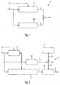
- FIG. 1 a schematic block diagram of a conventional device V for generating a residual r.
- the conventional device V corresponds to Fig. 1 a generalized presentation of the Fig. 4 of the US 2007/0124038 A1 In order to better represent the disadvantages of the prior art.
- the reference numeral z denotes a disturbance that maps external disturbances to the system S.
- the system S has the command variable w as an input variable and provides the system output variable y on the output side.
- the system S is a real electro-hydraulic rudder servo system and the system output y corresponds to a measured displacement of the actuator vault of the rudder servo system.
- a system model SM is arranged parallel to the system S.
- the estimation method described above essentially consists of the parallel system model or process model, which in the form of a mathematical description best approximates the initial values of the process or system and its parameterization.
- the identical input signal for the system S, the command variable or command value w is the only input signal of the system model SM.
- the estimated system output ⁇ of the system model SM results.
- the residual r the difference between the time-varying system output signal y and the estimated system output signal ⁇ of the system model SM formed.
- the residual r is used in case of exceeding a predefined threshold for identifying a system error.
- the process or the system S changes as a result of changes in parameters or boundary conditions, for example airspeed, altitude, setting and sliding angles, temperature, properties of the hydraulic system Medium of the actuator and the like, during operation or flight. These changes affect the response behavior of the system S and thus the momentum of the system S. They are not mapped by the parallel process model or system model SM.
- the evaluation module 23 compares the residual 24 with a predefined threshold value and counts every exceeding of this threshold value. After a predetermined number of counted overshoots of the predetermined threshold, an oscillatory error condition is detected and an output 26 is set to a positive logic value to indicate this error.
- this consists of a serial combination of a frequency-selective filter bank, unit numbered 27, and a downstream comparator stage, unit numbered 25, for each individual frequency band of the Residuums 24.
- the frequency-selective filter bank 27 consists from a parallel connection of bandpass filters for the spectral separation of the residual 24 into predetermined frequency bands.
- reference numeral 28 denotes a vector of the spectral components of the residual 24 in the frequency bands determined by the frequency-selective filter bank 27.
- the comparator bank 25 in each case comprises a separate channel for each component of the vector 28, in which the respective component is compared with a predefined threshold value.
- the case of exceeding is noted by means of a counter. If the number of counted overflows of a channel exceeds a predetermined limit, the oscillatory error is detected and indicated by means of the output signal 28.
- the detection thresholds must be increased accordingly and, if necessary, the number of required acknowledgment cycles must be increased. This has for the detection of continuous vibrations due to system errors a greatly reduced sensitivity and further increased detection time of the evaluation module result. This is particularly true of system errors in which an oscillating component is superimposed with a nominal low frequency system output signal.
- the EP 1 420 153 A2 discloses another apparatus and method for generating residuals for detecting system errors.
- this object is achieved by a device having the features of patent claim 1 and / or an aircraft having the features of patent claim 7 and / or by a method having the features of patent claim 8 and / or a computer program product having the features of patent claim 10.
- the respective means, the first to fourth means can be implemented by hardware or software technology.
- the respective means can be designed as a device, for example as a computer or microprocessor, as a device or as part of a system, for example as a computer system.
- the respective means may be designed as a computer program product, as a function, as a routine, as part of a program code or as an executable object.
- a computer program product which causes a program-controlled device to carry out a method for generating residuals as described above for detecting erroneous transients, drifts or oscillations in the system behavior of a system of an aircraft.
- the first to fourth means in particular form a Störbeobachter unit or a Störbeobachter.
- the observer invention enforces a follow-up behavior of the system model with respect to the estimated system output, for example, the piston position of the rudder servo system. This is achieved by returning the residual to the internal states of the system model via the observer feedback.
- the disturbance model is set up parallel to the observer feedback.
- the approximated or estimated disturbance which according to the invention is mapped as a disturbance model size, is also attributed to the internal states of the system model.
- an indirect effect of the external disturbances of the system in the estimated system output variable or in the disturbance observer output is additionally mapped.
- An advantage of the present invention is the robust generation of a residual by means of which the presence of an error, in particular in the form of erroneous transients, drift, creep or oscillations in a system of an aircraft is detectable.
- the evaluation is then carried out by comparing the residual with a predetermined threshold.
- external disturbances that have an effect on the process or the system are represented by the interference observer according to the invention as an approximation.
- Such external disturbances or process disturbances result essentially from air forces acting on the driven footprint during operation, particularly as transient disturbances from one-time events such as gusts, harmonic disturbances by periodic vortex shedding or effects from the flexibility of the surrounding structure or from stochastic disturbances such as turbulence , and according to the invention do not lead to a significant effect on the residuum.
- variable parameters are the airspeed, the altitude, the pitch and roll angle, the temperature, the hydraulic medium characteristics of the actuator, and the like. These changes affect the response and the momentum of the system. They are also imaged by the interferer according to the invention on the forced follow-up behavior and are therefore not visible in the residuum.
- the system model can be reduced by these elements.
- the measurable quantities are provided to the observer as additional input variables. They advantageously increase the quality of the estimated system output of the observer and further minimize the residual.
- the reduced observer can in this case be reduced to the subprocess or to the subsystem of the not directly measurable and / or reliable dynamic effects.
- the reduction of the complete observer to one in the fixed System equations integrated, reduced observer leads to a further increase in robustness and thus to accelerate the runtime characteristics of the proposed method.
- Fig. 2 shows a schematic block diagram of a first embodiment of a device E for Residuenaüs Edinburgh a Residuums r for detecting system errors in the system behavior of a system S of an aircraft.
- the system S receives a time-variable reference variable w and an external disturbance-measuring disturbance variable z.
- the system S provides a system output variable y on the output side.
- the device E for residual evaluation has at least one device V for residual generation of the residual r, a comparator unit KE, a first unit E1, a second unit E2 and a third unit E3.
- the device V is suitable for the residual generation of the residual r, wherein the device V generates the residual r at least as a function of the reference variable w and the system output variable y.
- the device V is, for example, according to one of the embodiments of FIGS. 4 or 5 educated.
- the comparator unit KE provides an evaluation result b by means of a comparison of the residual r with a threshold value s provided.
- the units E1 to E3 are provided.
- the first unit E1 is set up to provide a constant threshold value s0.
- the second unit E2 is set up to provide an adaptive threshold value s1 at least as a function of the time-variable reference variable w.
- the third unit E3 is set up to provide the threshold value s by means of a combination of the constant threshold component s0 with the adaptive threshold component s1.
- the third unit E3 adds the constant threshold value S0 to the adaptive threshold value s1 to form the threshold value s.
- the comparator unit KE sets the evaluation result b for indicating a system error to a positive logical value, if the provided residual r is greater than the provided threshold value s.
- the evaluation result b can also be embodied as a signal, for example as a continuous signal, which is set up to indicate the two possible states (r> s and r ⁇ s).
- Fig. 3 shows a second embodiment of an inventive device E for Residuenaustechnisch a Residuums r for detecting system errors in the system behavior of a system S of an aircraft.
- the second embodiment according to Fig. 3 includes all features of the first embodiment according to Fig. 2 which are therefore not shown again to avoid repetition.
- the first unit E1 is set up to provide the constant threshold value s0 as a function of an expected, inherent measurement noise mr of the system S.
- the first unit E1 preferably sets the constant threshold value s0 to a minimum value.
- the second unit E2 is set up to provide the adaptive threshold value s1 as a function of the time-variable reference variable w, at least one provided measured variable mg of the system S and / or a state variable zg estimated by means of a system model SM of the device V.
- the device E preferably has a fourth unit E4 which is set up to activate the comparator unit KE after a predetermined confirmation time has elapsed.
- the fourth unit E4 preferably controls the comparator unit KE by means of an activation signal a.
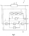
- FIG. 4 a schematic block diagram of an embodiment of the inventive device V for Residuengentechnik for detecting system errors, in particular of erroneous transients, drift or oscillations, shown in the system behavior of a system S of an aircraft.
- the residual generation device V for detecting erroneous transients, drifts or oscillations in the system behavior of a system S of an aircraft has a first means 1, a second means 2, a third means 3 and a fourth means 4.
- the first to fourth means 1-4 form a Störbeobachter unit SB.
- the system S receives a guidance input w and a disturbance variable z, which maps external disturbances onto the system S.
- the system provides a system output position y on the output side.
- the system S is, for example, an electro-hydraulic rudder control system of the aircraft, in which case the system output variable y is a measured displacement of the actuator piston of the position-controlled rudder control system S.
- the first means 1 has a system model SM for mapping the system S to be monitored.
- the first means 1 receives on the input side the reference variable w, an observer feedback variable b and a disturbance model variable ⁇ . Depending on this, the first means 1 provides on the output side an estimated system output ⁇ ( Fig. 4 ).
- the second means 2 is arranged to form a residue r from the difference between the system output y and the estimated system output ⁇ .
- the second means 2 is designed, for example, as a subtractor.
- the third means 3 is designed as an observer feedback L.
- the third means 3 receives on the input side the residual r and, depending on the received residual r, provides on the output side the observer feedback quantity bg for dynamic correction of the system model SM such that the estimated system output ⁇ follows the system output y.
- the fourth means 4 is equipped with a disturbance model ZM, which receives the residue r on the input side and, depending on the output side, provides the disturbance model variable ⁇ for mapping the effects or effects of the external disturbances onto the system model SM.
- the observer feedback L is set, in particular for the dynamic correction of the internal states of the system model SM, such that the estimated system output ⁇ follows the system output y, a decay of an initial disturbance and a follow-up behavior of the external disturbances due to a weighting of the residuals r and a return to the system model SM is provided.
- Fig. 5 shows a second embodiment of a device according to the invention V for Residuengener mich a Residuums r for detecting system errors, in particular of erroneous transients, drift or oscillations in the system behavior of a system S of an aircraft.
- the second embodiment according to Fig. 5 includes all features of the first embodiment according to Fig. 4 which are therefore not shown again to avoid repetition.
- the observer unit SB has an observer feedback matrix L for the formation of the observer feedback.
- the coefficients of the observer feedback matrix L are determined via a state controller design.
- the state controller design is formed, for example, by a pole specifier, an optimal regulator design, a robust ripple design design method, linear quadratic estimators (LQE), or nonlinear approaches.
- the disturbance model size ⁇ or estimated disturbance ⁇ is embodied as a dynamic disturbance model variable ⁇ , which is formed by means of a linear combination of artificial system states.
- the dynamic interference model variable ⁇ is preferably determined by means of a linear combination of an adjustment matrix K, an integrator 1 s and a disturbance variable matrix F formed.
- the control matrix K receives the residual r and the disturbance variable matrix F provides the disturbance model variable ⁇ on the output side.
- the integrator 1 s is arranged between the control matrix K and the disturbance variable matrix F.
- x denotes the system states of the linear system model SM, which can be obtained by integration by means of the integrator 1 s from temporal changes of the system states x ⁇ ⁇ result.
- Fig. 6 shows a schematic flow diagram of an embodiment of a method for residual evaluation of a residual r for detecting system errors in the system behavior of a system S of an aircraft.
- a residual r is generated at least as a function of the reference variable w and the system output variable y.
- a constant threshold value s0 is provided.
- An adaptive threshold value s1 is provided at least as a function of the time-variable reference variable w.
- a threshold value s is provided by means of a combination, in particular by means of an addition, of the constant threshold value s0 with the adaptive threshold value s1.
- the residual r is compared with the provided threshold value s for providing an evaluation result b. If the residual r is above the provided threshold value s, a system error of the system S is detected.
- Fig. 7 shows a schematic flow diagram of an embodiment of the inventive method for Residuengener ist a Residuums r for detecting system errors, especially of erroneous transients, drift or oscillations, in the system behavior of a system S of an aircraft, which receives a reference variable w and an external interference imaged disturbance z and the output side provides a system output y.
- the method according to the invention will be described below with reference to the block diagram in FIG Fig. 7 with reference to the block diagram in Fig. 4 described.
- the embodiment of the method according to the invention Fig. 7 has the following method steps S1 to S4:
- a system model SM for mapping the system S to be monitored is provided.
- the system model SM receives on the input side the reference variable w, an observer feedback quantity bg and a disturbance model variable z. Depending on this, the system model SM provides an estimated system output variable ⁇ on the output side.
- a residual r is made up of the difference between the system output y and the estimated system output ⁇ .
- An observer feedback loop L which receives the residue r on the input side and, depending on the output side, provides the observer feedback variable bg for the dynamic correction of the system model SM in such a way that the estimated system output ⁇ follows the system output variable y.
- An interference model ZM is provided which receives the residual r on the input side and, depending on the output side, provides the interference model variable ⁇ for mapping the effects or effects of the external interference onto the system model SM.
- the quantity of the estimated system variables preferably becomes in the system model SM is reduced by this extended measured variable and this further measured variable is fed directly to the system model SM as a further input variable.
- FIGS. 8 to 12 show schematic timing diagrams to illustrate the invention Residuenaustechnisch a Residuums r for detecting system errors FC in the system behavior of a system S of an aircraft.
- a rudder servo system as a system S is based on a first actuator - designated by the displacement of the actuator piston of the first actuator as the system output signal y1 - and a redundant second actuator - designated by the displacement of the actuator piston of the second actuator as the system output signal y2 ,
- FIG. 8 shows the time course of the system output signals y1 and y2.
- FIG. 9 shows the time course of the disorder z.
- FIG. 10 shows the time course of the residual r and the inventive threshold s.
- Figures 11 show the time course of the evaluation result b and the time course of a drive signal msv, which is generated as a function of the evaluation result b for selecting the actuator 1 or 2.
- FIG. 8 shows FIG. 8 the time course of the system output signals y1 and y2.
- the system output signals y1 and y2 increase significantly according to the guidance input w.
- FIG. 9 the time course of the disturbance z, which corresponds to a force with which the actuated by the actuator 1 or 2 footprint of the aircraft is loaded. This force is also referred to as aerodynamic load or air load.
- FIG. 10 the time course of the residual r and the inventive threshold s.
- the threshold value s is adjusted as a function of the guidance input w, ie the threshold value s is adjusted as a function of the jumping of the guidance input w and will therefore jump itself (see Fig. 10a )
- the threshold value s is adjusted as a function of the jumping of the guidance input w and will therefore jump itself (see Fig. 10a )
- FIG. 12 is at the end of a confirmation time BZ, which is for example 2 s, a drive signal msv from 1 to 0 switch over. This switching indicates that switching is made from the first actuator to the second actuator.
- a confirmation time BZ which is for example 2 s
- msv a drive signal from 1 to 0 switch over.
Landscapes
- Physics & Mathematics (AREA)
- Engineering & Computer Science (AREA)
- Artificial Intelligence (AREA)
- Evolutionary Computation (AREA)
- Mathematical Physics (AREA)
- General Physics & Mathematics (AREA)
- Automation & Control Theory (AREA)
- Feedback Control In General (AREA)
- Measurement Of Mechanical Vibrations Or Ultrasonic Waves (AREA)
- Testing And Monitoring For Control Systems (AREA)
- Traffic Control Systems (AREA)
- Electric Propulsion And Braking For Vehicles (AREA)
Description
Die vorliegende Erfindung betrifft eine Einrichtung und ein Verfahren zur Generierung eines Residuums zur Erkennung von fehlerhaften Transienten, Drift oder Oszillationen im Systemverhalten eines Systems eines Flugzeugs.The present invention relates to a device and a method for generating a residual for detecting erroneous transients, drifts or oscillations in the system behavior of a system of an aircraft.
Das technische Gebiet der Erfindung betrifft die Auswertung eines generierten Residuums zur Erkennung von Systemfehlern, insbesondere von fehlerhaften Transienten, Drift oder Oszillationen, im Systemverhalten eines Systems eines Flugzeuges, beispielsweise eines elektrohydraulischen Ruderstellsystems.The technical field of the invention relates to the evaluation of a generated residual for the detection of system errors, in particular of erroneous transients, drifts or oscillations, in the system behavior of a system of an aircraft, for example an electro-hydraulic rudder control system.
Überschreitet das generierte Residuum eine vorbestimmte Schwelle oder Schranke, so ist ein Fehler im Systemverhalten detektiert. Solche Systemfehler im Systemverhalten zeigen sich in Form von fehlerhaften Transienten, Drift oder Oszillationen im Eingangs-/Ausgangsverhalten des Systems.If the generated residual exceeds a predetermined threshold or barrier, an error in the system behavior is detected. Such system errors in the system behavior are reflected in the form of erroneous transients, drifts or oscillations in the input / output behavior of the system.
Dabei zieht die zunehmende Komplexität von Flugzeugsteuerungssystemen, insbesondere digitale Flugzeugsteuerungssysteme, die bei größtmöglicher Redundanz vor allem verbesserte Flugeigenschaften sowie eine Vielzahl an Sicherungsfunktionen und Komfortfunktionen ermöglichen, das vermehrte Auftreten zum Teil neuer Fehlerszenarien nach sich. Dazu zählen insbesondere nahezu ungedämpfte Stellflächenoszillationen der Stellflächen. Von besonderer Bedeutung sind dabei die OFC-Ursachen (OFC, Oscillatory Failure Case), welche durch Fehler im Stellsystem selbst auftreten oder sich aus den Flugsteuerungsrechnern oder der zur Erfassung der flugmechanischen Eigenbewegung vorgelagerten Sensorik in die Aktuatorregelkreise der jeweiligen Stellsysteme fortpflanzen.The increasing complexity of aircraft control systems, in particular digital aircraft control systems, which allow for the greatest possible redundancy especially improved flight characteristics and a variety of security features and comfort features, the increased occurrence of some new error scenarios after. These include in particular almost undamped footprint oscillations of the shelves. Of particular importance are the OFC causes (OFC, Oscillatory Failure Case), which occur due to errors in the control system itself or from the flight control computers or to capture the flight mechanics proper motion propagate upstream sensors in the Aktuatorregelkreise the respective control systems.
Die Vielzahl der denkbaren OFC-Szenarien umfasst dabei Fehler in Komponenten der Datenverarbeitung und der Signalverarbeitung, Softwarefehler, mechanische Defekte, beispielsweise in der Servoventilbaugruppe, oder Ausfälle von elektronischen Einzelbausteinen auf unterster Schaltkreisebene, zum Beispiel im Spannungs-Strom-Wandler.The multitude of conceivable OFC scenarios includes errors in components of data processing and signal processing, software errors, mechanical defects, for example in the servo valve assembly, or failures of individual electronic components on the lowest circuit level, for example in the voltage-current converter.
Weitere Fehlerszenarien können sich aus Wechselwirkungen zwischen den einzelnen Systemkomponenten des Aktuatorregelkreises oder des digitalen Flugsteuerungssystems ergeben.Other fault scenarios may arise from interactions between the individual system components of the actuator loop or the digital flight control system.
Zur Detektion von solchen Systemfehlern ist im Rahmen eines modellbasierten Diagnoseansatzes die Generierung des Residuums zur Identifikation einer fehlerbedingten Abweichung des Realsystemverhaltens vom nominalen, fehlerfreien Systemverhalten erforderlich. Dazu zeigt die Druckschrift
Zur Schätzung der Kolbenposition des realen, elektrohydraulischen Ruderstellsystems ist der Ansatz eines detaillierten, nicht linearen oder eines vereinfachten linearen Parallelmodells vorgesehen, welcher in der
In diesem Zusammenhang zeigt die
Dabei entspricht die herkömmliche Vorrichtung V nach
Mit Bezug auf
Das System S hat als Eingangsgröße die Führungsgröße w und stellt ausgangsseitig die System-Ausgangsgröße y bereit. Das System S ist beispielsweise ein reales elektrohydraulisches Ruderstellsystem und die System-Ausgangsgröße y entspricht einer gemessenen Verschiebung des Aktuatorkölbens des Ruderstellsystems. Zur Bereitstellung einer geschätzten System-Ausgangsgröße ŷ ist parallel zu dem System S ein Systemmodell SM angeordnet.The system S has the command variable w as an input variable and provides the system output variable y on the output side. For example, the system S is a real electro-hydraulic rudder servo system and the system output y corresponds to a measured displacement of the actuator vault of the rudder servo system. To provide an estimated system output ŷ, a system model SM is arranged parallel to the system S.
Der Kern des in der
Bei der Anwendung der in
Weiter haben hochdynamische Veränderungen der Führungsgröße w unter Anwesenheit von Störungen ein sehr rasches, kurzfristiges Anwachsen des Residuums r zur Folge.Furthermore, highly dynamic changes in the reference variable w in the presence of disturbances result in a very rapid, short-term increase in the residual r.
Des Weiteren verändert sich der Prozess oder das System S durch Änderungen von Parametern oder Randbedingungen, beispielsweise Fluggeschwindigkeit, Flughöhe, Anstell- und Schiebewinkel, Temperatur, Eigenschaften des hydraulischen Mediums des Aktuators und dergleichen, während des Betriebes oder Fluges. Diese Veränderungen wirken auf das Antwortverhalten des Systems S und damit auf die Eigendynamik des Systems S. Sie werden vom parallelen Prozessmodell oder Systemmodell SM nicht abgebildet.Furthermore, the process or the system S changes as a result of changes in parameters or boundary conditions, for example airspeed, altitude, setting and sliding angles, temperature, properties of the hydraulic system Medium of the actuator and the like, during operation or flight. These changes affect the response behavior of the system S and thus the momentum of the system S. They are not mapped by the parallel process model or system model SM.
Weiterhin können die Anfangswerte des Prozesses oder Systems S in praktischen Anwendungen lediglich durch ein Modell approximiert werden. Derart initiierte Abweichungen in der Systemantwort des Systemmodells SM sowie die Wirkung vernachlässigter und unbekannter Dynamik bleiben bei der aus der
Dies führt nachteiligerweise zu einem Signalanteil im Residuum, welcher eine sehr empfindliche Einstellung des Schwellwertes zur Fehlerdetektion ohne Einschränkung des überwachten Frequenzbandes ohne zusätzliche Maßnahmen erheblich erschwert.This disadvantageously leads to a signal component in the residual, which considerably complicates a very sensitive setting of the threshold value for error detection without limiting the monitored frequency band without additional measures.
In der
Das Auswertemodul 23 vergleicht das Residuum 24 mit einem vordefinierten Schwellwert und zählt jede Überschreitung dieses Schwellwertes. Nach einer vorbestimmten Anzahl von gezählten Überschreitungen des vorbestimmten Schwellwertes wird ein oszillatorischer Fehlerfall festgestellt und ein Ausgangssignal 26 wird auf einen positiven logischen Wert zur Anzeige dieses Fehlers gesetzt.The evaluation module 23 compares the residual 24 with a predefined threshold value and counts every exceeding of this threshold value. After a predetermined number of counted overshoots of the predetermined threshold, an oscillatory error condition is detected and an output 26 is set to a positive logic value to indicate this error.
Um eine gewisse Güte des Auswertemoduls 23 zu erreichen, besteht dieses aus einer seriellen Verknüpfung einer frequenzselektiven Filterbank, Einheit mit dem Bezugszeichen 27, und einer nachgeschalteten Komparatorstufe, Einheit mit dem Bezugszeichen 25, für jedes einzelne Frequenzband des Residuums 24. Die frequenzselektive Filterbank 27 besteht aus einer Parallelschaltung von Bandpassfiltern zur spektralen Trennung des Residuums 24 in vorbestimmte Frequenzbänder. Dabei bezeichnet das Bezugszeichen 28 einen Vektor der spektralen Anteile des Residuums 24 in den durch die frequenzselektive Filterbank 27 festgelegten Frequenzbändern.In order to achieve a certain quality of the evaluation module 23, this consists of a serial combination of a frequency-selective filter bank, unit numbered 27, and a downstream comparator stage, unit numbered 25, for each individual frequency band of the Residuums 24. The frequency-selective filter bank 27 consists from a parallel connection of bandpass filters for the spectral separation of the residual 24 into predetermined frequency bands. In this case, reference numeral 28 denotes a vector of the spectral components of the residual 24 in the frequency bands determined by the frequency-selective filter bank 27.
Dazu umfasst die Komparatorbank 25 jeweils einen gesonderten Kanal für jede Komponente des Vektors 28, in welchem die jeweilige Komponente mit einem vordefinierten Schwellwert verglichen wird. In jedem Kanal wird der Fall der Überschreitung mittels eines Zählers vermerkt. Übersteigt die Anzahl der gezählten Überschreitungen eines Kanals eine vorab bestimmte Schranke, wird der oszillatorische Fehlerfall festgestellt und mittels des Ausgangssignals 28 angezeigt.For this purpose, the
Bei der Anwendung dieser aus der
Ein weiterer Grund für die beschränkte Güte für die Überwachungsfunktion des Ruderstellsystems liegt im Übersprechen zwischen benachbarten Frequenzbereichen, da eine exakte Trennung technisch schwer realisierbar ist. Ein solches Übersprechen kann im Falle unterschiedlicher Schwellwerte vermehrt Fehlalarme auslösen.Another reason for the limited quality for the monitoring function of the rudder control system is in the crosstalk between adjacent frequency ranges, since an exact separation is technically difficult to achieve. Such crosstalk can trigger false alarms in the case of different thresholds.
Des Weiteren kann sich insbesondere aus dem strukturdynamischen Antwortverhalten eine Unsicherheit für die Festlegung der Grenzen der höheren Frequenzbänder in Kombination mit korrespondierenden festen Schwellwerten ergeben. Dies hat einen unmittelbaren nachteiligen Einfluss auf die zu erzielende Güte bei der Fehlererkennung im höheren Frequenzbereich. Durch die Anwendung der aus der
Die
Demnach ist es eine Aufgabe der vorliegenden Erfindung, eine Residuengenerierung zur Erkennung von Systemfehlern, insbesondere von fehlerhaften Transienten, Drift oder Oszillationen, im Systemverhalten eines Systems eines Flugzeugs zu schaffen, welche die oben beschriebenen Nachteile nicht aufweist.Accordingly, it is an object of the present invention to provide a residual generation for detecting system errors, in particular erroneous transients, drifts or oscillations, in the system behavior of a system of an aircraft which does not have the disadvantages described above.
Erfindungsgemäß wird diese Aufgabe durch eine Einrichtung mit den Merkmalen des Patentanspruchs 1 und/oder ein Flugzeug mit den Merkmalen des Patentanspruchs 7 und/oder durch ein Verfahren mit den Merkmalen des Patentanspruchs 8 und/oder ein Computerprogrammprodukt mit den Merkmalen des Patentanspruchs 10 gelöst.According to the invention, this object is achieved by a device having the features of
Demgemäß wird eine Vorrichtung zur Residuengenerierung zur Erkennung von fehlerhaften Transienten, Drift oder Oszillationen im Systemverhalten eines Systems eines Flugzeugs vorgeschlagen, welches eine Führungsvorgabe und eine externe Störungen abbildende Störgröße eingangsseitig empfängt und ausgangsseitig eine System-Ausgangsgröße bereitstellt, wobei die Vorrichtung aufweist:
- ein erstes Mittel mit einem System-Modell zur Abbildung des zu überwachenden Systems, welches eingangsseitig die Führungsgröße, eine Beobachterrückführgröße und eine Störmodellgröße empfängt und abhängig davon ausgangsseitig eine geschätzte System-Ausgangsgröße bereitstellt;
- ein zweites Mittel zur Bildung eines Residuums aus der Differenz zwischen der System-Ausgangsgröße und der geschätzten System-Ausgangsgröße;
- ein drittes Mittel mit einer Beobachter-Rückführung, welche eingangsseitig das Residuum empfängt und abhängig davon ausgangsseitig die Beobachterrückführgröße zur dynamischen Korrektur des Systemmodells derart bereitstellt, dass die geschätzte System-Ausgangsgröße der System-Ausgangsgröße folgt; und
- ein viertes Mittel mit einem Störmodell, welches eingangsseitig das Residuum empfängt und abhängig davon ausgangsseitig die Störmodellgröße zur Abbildung der Wirkungen der externen Störungen auf das System-Modell bereitstellt.
- a first means having a system model for mapping the system to be monitored, which receives on the input side the reference variable, an observer feedback variable and a disturbance model variable and, depending on the output side, provides an estimated system output variable;
- second means for forming a residual from the difference between the system output and the estimated system output;
- a third means with an observer feedback, which receives the residue on the input side and depending on the output side the observer feedback quantity for the dynamic correction the system model provides such that the estimated system output follows the system output; and
- a fourth means having a disturbance model which receives the residue on the input side and, depending on the output side, provides the disturbance model quantity for mapping the effects of the external disturbances on the system model.
Das jeweilige Mittel, das erste bis vierte Mittel, kann hardwaretechnisch oder auch softwaretechnisch implementiert sein. Bei einer hardwaretechnischen Implementierung kann das jeweilige Mittel als Vorrichtung, zum Bespiel als Computer oder Mikroprozessor, Einrichtung oder auch als Teil eines Systems, zum Bespiel als Computer-System, ausgebildet sein. Bei einer softwaretechnischen Implementierung kann das jeweilige Mittel als Computerprogrammprodukt, als eine Funktion, als eine Routine, als Teil eines Programmcodes oder als ausführbares Objekt ausgebildet sein.The respective means, the first to fourth means, can be implemented by hardware or software technology. In a hardware implementation, the respective means can be designed as a device, for example as a computer or microprocessor, as a device or as part of a system, for example as a computer system. In a software implementation, the respective means may be designed as a computer program product, as a function, as a routine, as part of a program code or as an executable object.
Des Weiteren wird ein Flugzeug mit zumindest einer wie oben beschriebenen Vorrichtung vorgeschlagen.Furthermore, an aircraft with at least one device as described above is proposed.
Weiterhin wird ein Verfahren zur Generierung eines Residuums (r) zur Erkennung von fehlerhaften Transienten, Drift oder Oszillationen im Systemverhalten eines Systems eines Flugzeugs vorgeschlagen. Das System empfängt eingangsseitig eine Führungsvorgabe und eine externe Störungen abbildende Störgröße und stellt ausgangsseitig eine System-Ausgangsgröße bereit. Das erfindungsgemäße Verfahren hat folgende Schritte:
- Bereitstellen eines System-Modells zur Abbildung des zu überwachenden Systems, welches eingangsseitig die Führungsgröße, eine Beobachterrückführgröße und eine Störmodellgröße empfängt und abhängig davon ausgangsseitig eine geschätzte System-Ausgangsgröße bereitstellt;
- Bilden eines Residuums aus der Differenz zwischen der System-Ausgangsgröße und der geschätzten System-Ausgangsgröße;
- Bereitstellen einer Beobachter-Rückführung, welche eingangsseitig das Residuum empfängt und abhängig davon ausgangsseitig die Beobachterrückführgröße zur dynamischen Korrektur des Systemmodells derart bereitstellt, dass die geschätzte System-Ausgangsgröße der System-Ausgangsgröße folgt; und
- Bereitstellen eines Störmodells, welches eingangsseitig das Residuum empfängt und abhängig davon ausgangsseitig die Störmodellgröße zur Abbildung der Wirkungen der externen Störungen auf das System-Modell bereitstellt, wobei die Störmodellgröße (z) als eine dynamische Störmodellgröße (z) ausgebildet ist, welche mittels einer Linearkombination einer Einregel-Matrix (K), eines Integrators

- Providing a system model for mapping the system to be monitored, which receives, on the input side, the reference variable, an observer feedback variable and a disturbance model variable and, depending on the output, provides an estimated system output variable;
- Forming a residual from the difference between the system output and the estimated system output;
- Providing an observer feedback which receives the residue on the input side and, depending on the output side, provides the observer feedback quantity for the dynamic correction of the system model in such a way that the estimated system output follows the system output variable; and
- Providing an interference model which receives the residue on the input side and, depending on the output side, provides the disturbance model variable for mapping the effects of the external disturbances on the system model, wherein the disturbance model variable (z) is designed as a dynamic disturbance model variable (z), which by means of a linear combination of a Einregel matrix (K), an integrator
Ferner wird ein Computerprogrammprodukt vorgeschlagen, welches auf einer programmgesteuerten Einrichtung die Durchführung eines wie oben beschriebenen Verfahrens zur Residuengenerierung zur Erkennung von fehlerhaften Transienten, Drift oder Oszillationen im Systemverhalten eines Systems eines Flugzeugs veranlasst.Furthermore, a computer program product is proposed, which causes a program-controlled device to carry out a method for generating residuals as described above for detecting erroneous transients, drifts or oscillations in the system behavior of a system of an aircraft.
Das erste bis vierte Mittel bilden insbesondere eine Störbeobachter-Einheit oder einen Störbeobachter.The first to fourth means in particular form a Störbeobachter unit or a Störbeobachter.
Der erfindungsgemäße Störbeobachter erzwingt ein Folgeverhalten des Systemmodells in Bezug auf die geschätzte System-Ausgangsgröße, beispielhaft die Kolbenposition des Ruderstellsystems. Dieses wird durch die Rückführung des Residuums über die Beobachterrückführung auf die internen Zustände des Systemmodells erreicht. Um Störungen auf den realen Prozess oder das reale System, insbesondere durch dynamische Luftlasten und Messrauschen für das Systemmodell, zu approximieren, wird das Störmodell parallel zur Beobachterrückführung aufgestellt. Die angenäherte oder geschätzte Störwirkung, welche erfindungsgemäß als Störmodellgröße abgebildet ist, wird ebenfalls auf die internen Zustände des Systemmodells zurückgeführt. Somit wird neben dem Folgeverhalten zusätzlich eine mittelbare Wirkung der externen Störungen des Systems in der geschätzten System-Ausgangsgröße bzw. im Störbeobachterausgang abgebildet.The observer invention enforces a follow-up behavior of the system model with respect to the estimated system output, for example, the piston position of the rudder servo system. This is achieved by returning the residual to the internal states of the system model via the observer feedback. In order to approximate disturbances to the real process or the real system, in particular by dynamic air loads and measurement noise for the system model, the disturbance model is set up parallel to the observer feedback. The approximated or estimated disturbance, which according to the invention is mapped as a disturbance model size, is also attributed to the internal states of the system model. Thus, in addition to the follow-up behavior, an indirect effect of the external disturbances of the system in the estimated system output variable or in the disturbance observer output is additionally mapped.
Ein Vorteil der vorliegenden Erfindung liegt in der robusten Generierung eines Residuums, mittels dem das Vorliegen eines Fehlers, insbesondere in Form von fehlerhaften Transienten, Drift, Kriechen oder Oszillationen bei einem System eines Flugzeuges detektierbar ist. Die Auswertung erfolgt dann durch Vergleich des Residuums mit einem vorbestimmten Schwellwert.An advantage of the present invention is the robust generation of a residual by means of which the presence of an error, in particular in the form of erroneous transients, drift, creep or oscillations in a system of an aircraft is detectable. The evaluation is then carried out by comparing the residual with a predetermined threshold.
Eine Einstellung robuster und hochempfindlicher Detektionsschwellwerte für das Residuum ist über die erfindungsgemäße Lösung möglich und ist mittels Tests mit realen Ruderstellsystemen Hardware-In-The-Loop gezeigt, deren Ergebnisse in Sachs, Helge: "Fault Investigation and Robust Failure Detection of Oscillatory Aircraft Actuation Systems Using Analytical Redundancy", Hamburg, Hamburg University of Technology, Aircraft Systems Engineering M-7, PhD thesis, nachgewiesen sind.A setting of robust and highly sensitive detection thresholds for the residual is possible via the solution according to the invention and is shown by means of tests with real rudder control systems Hardware-In-The-Loop, whose results in Sachs, Helge: "Fault Investigation and Robust Failure Detection of Oscillatory Aircraft Actuation Systems Using Analytical Redundancy, Hamburg, Hamburg University of Technology, Aircraft Systems Engineering M-7, PhD thesis.
Dabei werden externe Störungen, die auf den Prozess oder das System wirken, durch den erfindungsgemäßen Störbeobachter als Näherung abgebildet. Solche externe Störungen oder Prozessstörungen resultieren im Wesentlichen aus Luftkräften, die auf die angetriebene Stellfläche während des Betriebes wirken, insbesondere als transiente Störungen durch einmalige Ereignisse wie Böen, harmonische Störungen durch periodische Wirbelablösungen oder Effekte aus der Flexibilität der umgebenden Struktur oder aus stochastischen Störungen wie Turbulenzen, und führen erfindungsgemäß nicht zu einer signifikanten Wirkung auf das Residuum.In this case, external disturbances that have an effect on the process or the system are represented by the interference observer according to the invention as an approximation. Such external disturbances or process disturbances result essentially from air forces acting on the driven footprint during operation, particularly as transient disturbances from one-time events such as gusts, harmonic disturbances by periodic vortex shedding or effects from the flexibility of the surrounding structure or from stochastic disturbances such as turbulence , and according to the invention do not lead to a significant effect on the residuum.
Des Weiteren hat eine permanente Überlagerung der gemessenen Aktuatorposition als System-Ausgangsgröße mit Messrauschen (beispielsweise ausgedrückt durch das Signalrauschverhältnis) der Positionsaufnehmer an der Aktuatorkolbenstange) keinen signifikanten Einfluss auf das generierte Residuum.Furthermore, a permanent superimposition of the measured actuator position as a system output variable with measurement noise (for example expressed by the signal to noise ratio) of the position sensors on the actuator piston rod has no significant influence on the generated residual.
Wie oben bereits ausgeführt, verändert sich das System oder der Prozess durch Änderungen von Parametern oder Randbedingungen während des Betriebes. Beispiele für solche veränderlichen Parameter sind die Fluggeschwindigkeit, die Flughöhe, der Anstell- und Schiebewinkel, die Temperatur, die Eigenschaften des hydraulischen Mediums des Aktuators und dergleichen. Diese Veränderungen wirken auf das Antwortverhalten und die Eigendynamik des Systems. Sie werden vom erfindüngsgemäßen Störbeobachter über das erzwungene Folgeverhalten ebenfalls abgebildet und werden im Residuum damit nicht sichtbar.As stated above, the system or process changes due to changes in parameters or constraints during operation. Examples of such variable parameters are the airspeed, the altitude, the pitch and roll angle, the temperature, the hydraulic medium characteristics of the actuator, and the like. These changes affect the response and the momentum of the system. They are also imaged by the interferer according to the invention on the forced follow-up behavior and are therefore not visible in the residuum.
Unterschiedliche Anfangswerte im System und im Systemmodell werden ebenfalls über die Beobachterrückführung minimiert. Somit haben sie keine weiteren Auswirkungen auf das erfindungsgemäß generierte Residuum.Different initial values in the system and in the system model are also minimized via the observer feedback. Thus, they have no further effects on the residual generated according to the invention.
Sind weitere Messgrößen des Systems verfügbar oder vorab sicher beschreibbar, kann das Systemmodell um diese Elemente reduziert werden. Die messbaren Größen werden als zusätzliche Eingangsgrößen dem Störbeobachter bereitgestellt. Sie erhöhen vorteilhafterweise die Güte der geschätzten System-Ausgangsgröße des Störbeobachters und minimieren weiter das Residuum.If further measured quantities of the system are available or can be written to safely in advance, the system model can be reduced by these elements. The measurable quantities are provided to the observer as additional input variables. They advantageously increase the quality of the estimated system output of the observer and further minimize the residual.
Sind Teile des Prozesses oder des Systems fest determiniert, werden diese aus dem Störbeobachter extrahiert. Der reduzierte Störbeobachter kann sich in diesem Fall auf den Teilprozess oder auf das Teilsystem der nicht unmittelbar messbaren und/oder sicheren dynamischen Effekte reduzieren. Die Reduktion des vollständigen Störbeobachters auf einen in die feststehenden Systemgleichungen integrierten, reduzierten Störbeobachter führt zu einer weiteren Steigerung der Robustheit und damit zur Beschleunigung der Laufzeiteigenschaften des vorgeschlagenen Verfahrens.If parts of the process or system are firmly determined, they are extracted from the observer. The reduced observer can in this case be reduced to the subprocess or to the subsystem of the not directly measurable and / or reliable dynamic effects. The reduction of the complete observer to one in the fixed System equations integrated, reduced observer leads to a further increase in robustness and thus to accelerate the runtime characteristics of the proposed method.
Die Erfindung wird im Folgenden anhand von Ausführungsbeispielen unter Bezugnahme auf die beiliegenden Figuren der Zeichnung näher erläutert.The invention is explained in more detail below on the basis of exemplary embodiments with reference to the accompanying figures of the drawing.
Von den Figuren zeigen:
- Fig. 1
- ein schematisches Blockschaltbild eines Ausführungsbeispiels einer herkömmlichen Vorrichtung zur Residuengenerierung zur Erkennung von Systemfehlern eines Systems eines Flugzeugs;
- Fig. 2
- ein schematisches Blockschaltbild eines ersten Ausführungsbeispiels einer Einrichtung zur Residuenauswertung eines Residuums zur Erkennung von Systemfehlern im Systemverhalten eines Systems eines Flugzeugs;
- Fig. 3
- ein schematisches Blockschaltbild eines zweiten Ausführungsbeispiels einer Einrichtung zur Residuenauswertung eines Residuums zur Erkennung von Systemfehlern im Systemverhalten eines Systems eines Flugzeugs;
- Fig. 4
- ein schematisches Blockschaltbild eines ersten Ausführungsbeispiels einer Vorrichtung zur Residuengenerierung zur Erkennung von Systemfehlern im Systemverhalten eines Systems eines Flugzeugs;
- Fig. 5
- ein schematisches Blockschaltbild eines zweiten Ausführungsbeispiels einer Vorrichtung zur Residuengenerierung zur Erkennung von Systemfehlern im Systemverhalten eines Systems eines Flugzeugs;
- Fig. 6
- ein schematisches Ablaufdiagramm eines Ausführungsbeispiels eines Verfahrens zur Residuenauswertung eines Residuums zur Erkennung von Systemfehlern im Systemverhalten eines Systems eines Flugzeugs;
- Fig. 7
- ein schematisches Ablaufdiagramm eines Ausführungsbeispiels eines Verfahrens zur Residuengenerierung zur Erkennung von Systemfehlern im Systemverhalten eines Systems eines Flugzeugs; und
- Fig. 8-12
- schematische Zeitdiagramme zur Illustrierung der erfindungsgemäßen Residuenauswertung eines Residuums zur Erkennung von Systemfehlern im Systemverhalten eines Systems eines Flugzeuges.
- Fig. 1
- a schematic block diagram of an embodiment of a conventional device for residual generation for detecting system errors of a system of an aircraft;
- Fig. 2
- a schematic block diagram of a first embodiment of a device for Residueauswertung a Residuums for detecting system errors in the system behavior of a system of an aircraft;
- Fig. 3
- a schematic block diagram of a second embodiment of a device for Residueauswertung a Residuums for detecting system errors in the system behavior of a system of an aircraft;
- Fig. 4
- a schematic block diagram of a first embodiment of a device for generating residuals to detect system errors in the system behavior of a system of an aircraft;
- Fig. 5
- a schematic block diagram of a second embodiment of a device for generating residuals to detect system errors in the system behavior of a system of an aircraft;
- Fig. 6
- a schematic flow diagram of an embodiment of a method for residual evaluation of a residual for detecting system errors in the system behavior of a system of an aircraft;
- Fig. 7
- a schematic flow diagram of an embodiment of a method for Residuengenierung for detecting system errors in the system behavior of a system of an aircraft; and
- Fig. 8-12
- schematic time charts illustrating the Residuenauswertung a Residuums invention for detecting system errors in the system behavior of a system of an aircraft.
In den Figuren bezeichnen dieselben Bezugszeichen gleiche oder funktionsgleiche Komponenten, soweit nichts Gegenteiliges angegeben ist.In the figures, the same reference numerals designate the same or functionally identical components, unless indicated otherwise.
Die Vorrichtung V ist zur Residuengenerierung des Residuums r geeignet, wobei die Vorrichtung V das Residuum r zumindest in Abhängigkeit der Führungsgröße w und der System-Ausgangsgröße y generiert.The device V is suitable for the residual generation of the residual r, wherein the device V generates the residual r at least as a function of the reference variable w and the system output variable y.
Die Vorrichtung V ist beispielsweise nach einem der Ausführungsbeispiele der
Die Komparator-Einheit KE stellt ein Auswerte-Ergebnis b mittels eines Vergleichs des Residuums r mit einem bereitgestellten Schwellenwert s bereit.The comparator unit KE provides an evaluation result b by means of a comparison of the residual r with a threshold value s provided.
Zur Bereitstellung des Schwellenwertes s sind die Einheiten E1 bis E3 vorgesehen.To provide the threshold value s, the units E1 to E3 are provided.
Dabei ist die erste Einheit E1 dazu eingerichtet, einen konstanten Schwellwertanteil s0 bereitzustellen.In this case, the first unit E1 is set up to provide a constant threshold value s0.
Die zweite Einheit E2 ist dazu eingerichtet, einen adaptiven Schwellwertanteil s1 zumindest in Abhängigkeit der zeitlich veränderlichen Führungsgröße w bereitzustellen.The second unit E2 is set up to provide an adaptive threshold value s1 at least as a function of the time-variable reference variable w.
Ferner ist die dritte Einheit E3 dazu eingerichtet, den Schwellwert s mittels einer Verknüpfung des konstanten Schwellwertanteils s0 mit dem adaptiven Schwellwertanteil s1 bereitzustellen. Insbesondere addiert die dritte Einheit E3 den konstanten Schwellwert S0 mit dem adaptiven Schwellwert s1 zur Ausbildung des Schwellwertes s.Furthermore, the third unit E3 is set up to provide the threshold value s by means of a combination of the constant threshold component s0 with the adaptive threshold component s1. In particular, the third unit E3 adds the constant threshold value S0 to the adaptive threshold value s1 to form the threshold value s.
Die Komparator-Einheit KE setzt das Auswerte-Ergebnis b zur Anzeige eines Systemfehlers auf einen positiven logischen Wert, falls das bereitgestellte Residuum r größer als der bereitgestellte Schwellwert s ist. Alternativ kann das Auswerte-Ergebnis b auch als ein Signal, beispielsweise als ein kontinuierliches Signal, ausgebildet sein, das dazu eingerichtet ist, die beiden möglichen Zustände (r > s und r ≤ s) anzuzeigen.The comparator unit KE sets the evaluation result b for indicating a system error to a positive logical value, if the provided residual r is greater than the provided threshold value s. Alternatively, the evaluation result b can also be embodied as a signal, for example as a continuous signal, which is set up to indicate the two possible states (r> s and r≤s).
Das zweite Ausführungsbeispiel gemäß
Gemäß dem zweiten Ausführungsbeispiel der erfindungsgemäßen Einrichtung E ist die erste Einheit E1 dazu eingerichtet, den konstanten Schwellwertanteil s0 in Abhängigkeit eines zu erwartenden, inhärenten Messrauschens mr des Systems S bereitzustellen.According to the second exemplary embodiment of the device E according to the invention, the first unit E1 is set up to provide the constant threshold value s0 as a function of an expected, inherent measurement noise mr of the system S.
Dabei stellt die erste Einheit E1 den konstanten Schwellwert s0 vorzugsweise auf einen minimalen Wert.In this case, the first unit E1 preferably sets the constant threshold value s0 to a minimum value.
Weiterhin ist gemäß
Weiter weist die Einrichtung E vorzugsweise eine vierte Einheit E4 auf, welche dazu eingerichtet ist, die Komparator-Einheit KE nach Ablauf einer vorbestimmten Bestätigungszeit zu aktivieren. Hierzu steuert die vierte Einheit E4 die Komparator-Einheit KE vorzugsweise mittels eines Aktivierungssignals a.Furthermore, the device E preferably has a fourth unit E4 which is set up to activate the comparator unit KE after a predetermined confirmation time has elapsed. For this purpose, the fourth unit E4 preferably controls the comparator unit KE by means of an activation signal a.
Beispiele für die Vorrichtung V zur Residuengenerierung des Residuums r sind in den
Dazu ist in
Die Vorrichtung V zur Residuengenerierung zur Erkennung von fehlerhaften Transienten, Drift oder Oszillationen im Systemverhalten eines Systems S eines Flugzeuges hat ein erstes Mittel 1, ein zweites Mittel 2, ein drittes Mittel 3 und ein viertes Mittel 4. Das erste bis vierte Mittel 1-4 bilden eine Störbeobachter-Einheit SB. Das System S empfängt eingangsseitig eine Führungsvorgabe w und eine Störgröße z, welche externe Störungen auf das System S abbildet. Abhängig davon stellt das System ausgangsseitig eine System-Ausgangsposition y bereit. Das System S ist beispielsweise ein elektrohydraulisches Ruderstellsystem des Flugzeuges, wobei dann die System-Ausgangsgröße y eine gemessene Verschiebung des Aktuatorkolbens des positionsgeregelten Ruderstellsystems S ist.The residual generation device V for detecting erroneous transients, drifts or oscillations in the system behavior of a system S of an aircraft has a
Das erste Mittel 1 hat ein System-Modell SM zur Abbildung des zu überwachenden Systems S. Das erste Mittel 1 empfängt eingangsseitig die Führungsgröße w, eine Beobachterrückführgröße b und eine Störmodellgröße ẑ. Abhängig davon stellt das erste Mittel 1 ausgangsseitig eine geschätzte System-Ausgangsgröße ŷ bereit (
Das zweite Mittel 2 ist dazu eingerichtet, ein Residuum r aus der Differenz zwischen der System-Ausgangsgröße y und der geschätzten System-Ausgangsgröße ŷ zu bilden. Das zweite Mittel 2 ist beispielsweise als ein Subtrahierer ausgebildet.The second means 2 is arranged to form a residue r from the difference between the system output y and the estimated system output ŷ. The second means 2 is designed, for example, as a subtractor.
Das dritte Mittel 3 ist als eine Beobachter-Rückführung L ausgebildet. Das dritte Mittel 3 empfängt eingangsseitig das Residuum r und stellt in Abhängigkeit des empfangenen Residuums r ausgangsseitig die Beobachterrückführgröße bg zur dynamischen Korrektur des Systemmodells SM derart bereit, dass die geschätzte System-Ausgangsgröße ŷ der System-Ausgangsgröße y folgt.The third means 3 is designed as an observer feedback L. The third means 3 receives on the input side the residual r and, depending on the received residual r, provides on the output side the observer feedback quantity bg for dynamic correction of the system model SM such that the estimated system output ŷ follows the system output y.
Des Weiteren ist das vierte Mittel 4 mit einem Störmodell ZM ausgestattet, welches eingangsseitig das Residuum r empfängt und abhängig davon ausgangsseitig die Störmodellgröße ẑ zur Abbildung der Wirkungen oder Effekte der externen Störungen auf das System-Modell SM bereitstellt.Furthermore, the
Die Beobachterrückführung L ist insbesondere zur dynamischen Korrektur der inneren Zustände des System-Modells SM derart eingestellt, dass die geschätzte System-Ausgangsgröße ŷ der System-Ausgangsgröße y folgt, wobei ein Abklingen einer Anfangsstörung und ein Folgeverhalten der externen Störungen durch eine Gewichtung der Residuen r und eine Rückführung auf das Systemmodell SM bereitgestellt wird.The observer feedback L is set, in particular for the dynamic correction of the internal states of the system model SM, such that the estimated system output ŷ follows the system output y, a decay of an initial disturbance and a follow-up behavior of the external disturbances due to a weighting of the residuals r and a return to the system model SM is provided.
Das zweite Ausführungsbeispiel gemäß
Gemäß dem zweiten Ausführungsbeispiel der erfindungsgemäßen Vorrichtung V hat die Störbeobachter-Einheit SB eine Beobachterrückführmatrix L zur Ausbildung der Beobachterrückführung. Dabei werden die Koeffizienten der Beobachterrückführmatrix L über einen Zustandsreglerentwurf bestimmt. Der Zustandsreglerentwurf ist beispielsweise durch eine Polvorgabe, durch einen optimalen Reglerentwurf, durch ein Entwurfsverfahren zum Entwurf robuster Rückführungen, durch lineare quadratische Schätzer (LQE; Linear Quadratic Estimator) oder durch nicht lineare Ansätze ausgebildet.According to the second embodiment of the device V according to the invention, the observer unit SB has an observer feedback matrix L for the formation of the observer feedback. The coefficients of the observer feedback matrix L are determined via a state controller design. The state controller design is formed, for example, by a pole specifier, an optimal regulator design, a robust ripple design design method, linear quadratic estimators (LQE), or nonlinear approaches.
Ferner ist die Störmodellgröße ẑ oder geschätzte Störgröße ẑ als eine dynamische Störmodellgröße ẑ ausgebildet, welche mittels einer Linearkombination künstlicher Systemzustände gebildet wird.Furthermore, the disturbance model size ẑ or estimated disturbance ẑ is embodied as a dynamic disturbance model variable ẑ, which is formed by means of a linear combination of artificial system states.
Dabei wird die dynamische Störmodellgröße ẑ vorzugsweise mittels einer Linearkombination einer Einregel-Matrix K, eines Integrators ![]()
![]()
![]()
![]()
![]()
![]()
![]()
![]()
Nachfolgend wird das erfindungsgemäße Verfahren anhand des Blockschaltbildes in
Ein Residuum r wird zumindest in Abhängigkeit der Führungsgröße w und der System-Ausgangsgröße y generiert.A residual r is generated at least as a function of the reference variable w and the system output variable y.
Ein konstanter Schwellwertanteil s0 wird bereitgestellt.A constant threshold value s0 is provided.
Ein adaptiver Schwellwertanteil s1 wird zumindest in Abhängigkeit der zeitlich veränderlichen Führungsgröße w bereitgestellt.An adaptive threshold value s1 is provided at least as a function of the time-variable reference variable w.
Ein Schwellwert s wird mittels einer Verknüpfung, insbesondere mittels einer Addition, des konstanten Schwellwertanteils s0 mit dem adaptiven Schwellwertanteil s1 bereitgestellt.A threshold value s is provided by means of a combination, in particular by means of an addition, of the constant threshold value s0 with the adaptive threshold value s1.
Das Residuum r wird mit dem bereitgestellten Schwellwert s zur Bereitstellung eines Auswerte-Ergebnisses b verglichen. Liegt das Residuum r über dem bereitgestellten Schwellwert s, so ist ein Systemfehler des Systems S festgestellt.The residual r is compared with the provided threshold value s for providing an evaluation result b. If the residual r is above the provided threshold value s, a system error of the system S is detected.
Nachfolgend wird das erfindungsgemäße Verfahren anhand des Blockschaltbildes in
Ein Systemmodell SM zur Abbildung des zu überwachenden Systems S wird bereitgestellt. Das Systemmodell SM empfängt eingangsseitig die Führungsgröße w, eine Beobachterrückführgröße bg und eine Störmodellgröße z. Abhängig davon stellt das Systemmodell SM ausgangsseitig eine geschätzte System-Ausgangsgröße ŷ bereit.A system model SM for mapping the system S to be monitored is provided. The system model SM receives on the input side the reference variable w, an observer feedback quantity bg and a disturbance model variable z. Depending on this, the system model SM provides an estimated system output variable ŷ on the output side.
Ein Residuum r wird aus der Differenz zwischen der System-Ausgangsgröße y und der geschätzten System-Ausgangsgröße ŷ gebildet.A residual r is made up of the difference between the system output y and the estimated system output ŷ.
Eine Beobachter-Rückführung L wird bereitgestellt, welche eingangsseitig das Residuum r empfängt und abhängig davon ausgangsseitig die Beobachterrückführgröße bg zur dynamischen Korrektur des Systemmodells SM derart bereitstellt, dass die geschätzte System-Ausgangsgröße ŷ der System-Ausgangsgröße y folgt.An observer feedback loop L is provided which receives the residue r on the input side and, depending on the output side, provides the observer feedback variable bg for the dynamic correction of the system model SM in such a way that the estimated system output ŷ follows the system output variable y.
Ein Störmodell ZM wird bereitgestellt, welches eingangsseitig das Residuum r empfängt und abhängig davon ausgangsseitig die Störmodellgröße ẑ zur Abbildung der Wirkungen oder Effekte der externen Störungen auf das Systemmodell SM bereitstellt.An interference model ZM is provided which receives the residual r on the input side and, depending on the output side, provides the interference model variable ẑ for mapping the effects or effects of the external interference onto the system model SM.
Vorzugsweise wird bei festgestellter Verfügbarkeit einer weiteren Messgröße des Systems S die Menge der geschätzten Systemgrößen im System-Modell SM um diese erweiterte Messgröße reduziert und diese weitere Messgröße wird dem System-Modell SM als weitere Eingangsgröße direkt zugeführt.If a further measured variable of the system S is determined to be available, the quantity of the estimated system variables preferably becomes in the system model SM is reduced by this extended measured variable and this further measured variable is fed directly to the system model SM as a further input variable.
Die
Dem Beispiel der
Dabei zeigt
Wie oben bereits ausgeführt, zeigt
Weiter zeigt
Weiterhin zeigt
Zum Zeitpunkt t = 25 s tritt hingegen ein Systemfehler FC auf, der in einem Schwingen der System-Ausgangssignale y1 und y2 resultiert. Nachdem sich zu diesem Zeitpunkt t = 25 s die Führungsvorgabe w nicht ändert, wird auch der Schwellwert s nicht angepasst. Folglich wird zum Zeitpunkt t = 25 s das Residuum r den bereitgestellten Schwellenwert s übersteigen. Dies ist im Detail in
Folglich wird hier gemäß
Gemäß
Erfindungsgemäß kann die Bestätigungszeit auch auf 0 gesetzt werden, da bereits zum Zeitpunkt t = 25 s feststeht, dass eine Umschaltung von dem Aktuator 1 auf den Aktuator 2 notwendig ist.According to the invention, the confirmation time can also be set to 0, since it is already established at the time t = 25 s that a changeover from the
Obwohl die vorliegende Erfindung anhand bevorzugter Ausführungsbeispiele vorliegend beschrieben wurde, ist sie darauf nicht beschränkt, sondern auf vielfältige Weise modifizierbar.Although the present invention has been described in terms of preferred embodiments herein, it is not limited thereto, but modifiable in a variety of ways.
1 erstes Mittel
2 zweites Mittel
3 drittes Mittel
4 viertes Mittel
a Aktivierungssignal
BZ Bestätigungszeit
b Auswerte-Ergebnis
bg Beobachterrückführgröße oder Ausgangssignal der Beobachterrückführung
A Systemmatrix des linearen Systemmodells SM
B Eingangsmatrix des linearen Systemmodells SM
C Ausgabematrix des linearen Systemmodells SM
E1 erste Einheit
E2 zweite Einheit
E3 dritte Einheit
E4 vierte Einheit
F Störgrößenmatrix
KE Komparator-Einheit
K Einregler-Matrix
L Beobachterrückführmatrix
mg Messgröße
mr Messrauschen
R1-R5 Verfahrensschritt
r Residuum
S System
S1-S4 Verfahrensschritt
SB Störbeobachter-Einheit
SM System-Modell
FC Systemfehler
w Führungsgröße
y System-Ausgangsgröße
ŷ geschätzte System-Ausgangsgröße
z Störgröße
zg Zustandsgröße
ẑ Störmodellgröße
ZM Störmodell
![]()
1 first agent
2 second means
3 third average
4 fourth mean
a activation signal
BZ confirmation time
b evaluation result
bg observer feedback or output of the observer feedback
A system matrix of the linear system model SM
B input matrix of the linear system model SM
C output matrix of the linear system model SM
E1 first unit
E2 second unit
E3 third unit
E4 fourth unit
F disturbance variable matrix
KE comparator unit
K Inverter matrix
L observer feedback matrix
mg measurand
mr measurement noise
R1-R5 process step
r residuum
S system
S1-S4 process step
SB interference observer unit
SM system model
FC system error
w reference variable
y system output
ŷ estimated system output
z disturbance
zg state size
ẑ fault model size
ZM interference model
![]()
Claims (10)
- Apparatus (V) for generating a residuum (r) for detecting erroneous transients, drift or oscillations in the system behaviour of a system (S) of an aircraft, which system receives on the input-side a guide default (w) and a disturbance variable (z) which reproduces external disturbances, and provides on the output side a system output variable (y), comprising:a) a first means (1) comprising a system model (SM) for reproducing the system (S) to be monitored which receives on the input-side the guide variable (w), an observer feedback variable (bg) and a disturbance model variable (z), and as a function thereof provides on the output-side an estimated system output variable (ŷ);b) a second means (2) for forming a residuum (r) from the difference between the system output variable (y) and the estimated system output variable (ŷ);c) a third means (3) comprising an observer feedback, which receives on the input-side the residuum (r) and as a function thereof provides on the output-side the observer feedback variable (bg) for dynamic correction of the system model (SM) such that the estimated system output variable (ŷ) follows the system output variable (y); andd) a fourth means (4) comprising a disturbance model (ZM) which receives on the input-side the residuum (r) and as a function thereof provides on the output-side the disturbance model variable (ẑ) for reproducing the effects of the external disturbances on the system model (SM), wherein the disturbance model variable (ẑ) is formed as a dynamic disturbance model variable (ẑ) which is formed by means of a linear combination of a tuning matrix (K), an integrator

- Apparatus as claimed in claim 1,
characterised in that
the system (S) is an electrohydraulic rudder adjustment system of the aircraft. - Apparatus as claimed in claim 2,
characterised in that
the system output variable (y) is a measured displacement of the actuator piston of the position-controlled rudder adjustment system (S) or the measured control surface position of the aircraft. - Apparatus as claimed in any one of claims 1 to 3,
characterised in that
the observer feedback is set for dynamic correction of the internal states of the system model (SM) such that the estimated system output variable (ŷ) follows the system output variable (y), wherein a decay of an initial disturbance and a following behaviour of the external disturbances is provided by weighting of the residua (r) and feedback into the system model (SM). - Apparatus as claimed in claim 4,
characterised in that
the observer feedback comprises an observer feedback matrix (L). - Apparatus as claimed in claim 5,
characterised in that
coefficients of the observer feedback matrix (L) are determined via a state controller design, in particular via a pole default, an optimum controller design, design methods for designing robust feedbacks, linear quadratic estimators (LQEs) or non-linear approaches. - Aircraft comprising one or a plurality of apparatuses (V) as claimed in any one of claims 1 to 6.
- Method for generating a residuum (r) for detecting erroneous transients, drift or oscillations in the system behaviour of a system (S) of an aircraft, which system receives on the input-side a guide default (w) and a disturbance variable (z), which reproduces external disturbances, and provides on the output-side a system output variable (y), having the steps of:a) providing a system model (SM) for reproducing the system (S) to be monitored, which receives on the input-side the guide variable (w), an observer feedback variable (bg) and a disturbance model variable (ẑ) and as a function thereof provides on the output-side an estimated system output variable (ŷ);b) forming a residuum (r) from the difference between the system output variable (y) and the estimated system output variable (ŷ);c) providing an observer feedback which receives on the input-side the residuum (r) and as a function thereof provides on the output-side the observer feedback variable (bg) for dynamic correction of the system model (SM) such that the estimated system output variable (ŷ) follows the system output variable (y); andd) providing a disturbance model (ZM) which receives on the input-side the residuum (r) and as a function thereof provides on the output-side the disturbance model variable (ẑ) for reproducing the effects of the external disturbances on the system model (SM), wherein the disturbance model variable (ẑ) is formed as a dynamic disturbance model variable (ẑ) which is formed by means of a linear combination of a tuning matrix (K), an integrator
- Method as claimed in claim 8,
characterised in that
when a further measurement variable of the system (S) is available, the system model (SM) is reduced by this further measurement variable and this further measurement variable is supplied to the system model (SM) as a further input variable. - Computer program product which causes a method as claimed in claim 8 or 9 to be carried out on a program-controlled device.
Priority Applications (1)
| Application Number | Priority Date | Filing Date | Title |
|---|---|---|---|
| EP12191846.0A EP2557467A3 (en) | 2009-04-28 | 2010-04-28 | Device and method for the evaluation of a residual for detecting systematic errors in the system behaviour of a system of an aircraft |
Applications Claiming Priority (3)
| Application Number | Priority Date | Filing Date | Title |
|---|---|---|---|
| US17323909P | 2009-04-28 | 2009-04-28 | |
| DE102009002682A DE102009002682B4 (en) | 2009-04-28 | 2009-04-28 | Device and method for residual evaluation of a residual for detecting system errors in the system behavior of a system of an aircraft |
| PCT/EP2010/055664 WO2010125080A2 (en) | 2009-04-28 | 2010-04-28 | Device and method for the residual analysis of a residuum to detect system errors in the system behavior of an aircraft |
Related Child Applications (1)
| Application Number | Title | Priority Date | Filing Date |
|---|---|---|---|
| EP12191846.0A Division-Into EP2557467A3 (en) | 2009-04-28 | 2010-04-28 | Device and method for the evaluation of a residual for detecting systematic errors in the system behaviour of a system of an aircraft |
Publications (2)
| Publication Number | Publication Date |
|---|---|
| EP2425308A2 EP2425308A2 (en) | 2012-03-07 |
| EP2425308B1 true EP2425308B1 (en) | 2016-06-15 |
Family
ID=42972759
Family Applications (2)
| Application Number | Title | Priority Date | Filing Date |
|---|---|---|---|
| EP12191846.0A Withdrawn EP2557467A3 (en) | 2009-04-28 | 2010-04-28 | Device and method for the evaluation of a residual for detecting systematic errors in the system behaviour of a system of an aircraft |
| EP10717620.8A Not-in-force EP2425308B1 (en) | 2009-04-28 | 2010-04-28 | Device and method for the residual analysis of a residuum to detect system errors in the system behavior of an aircraft |
Family Applications Before (1)
| Application Number | Title | Priority Date | Filing Date |
|---|---|---|---|
| EP12191846.0A Withdrawn EP2557467A3 (en) | 2009-04-28 | 2010-04-28 | Device and method for the evaluation of a residual for detecting systematic errors in the system behaviour of a system of an aircraft |
Country Status (6)
| Country | Link |
|---|---|
| US (1) | US9535419B2 (en) |
| EP (2) | EP2557467A3 (en) |
| CN (1) | CN102483626B (en) |
| DE (2) | DE102009002682B4 (en) |
| RU (1) | RU2501063C2 (en) |
| WO (1) | WO2010125080A2 (en) |
Families Citing this family (18)
| Publication number | Priority date | Publication date | Assignee | Title |
|---|---|---|---|---|
| FR2978585B1 (en) | 2011-07-26 | 2013-08-16 | Airbus Operations Sas | METHOD AND DEVICE FOR AUTOMATICALLY ESTIMATING A FLIGHT PARAMETER VECTOR OF AN AIRCRAFT, AND METHOD AND ASSEMBLY FOR DETECTING FAILURE AFFECTING SUCH A VECTOR |
| CN102385311B (en) * | 2011-09-15 | 2013-08-07 | 江苏科技大学 | Electrohydraulic linear-velocity digital servo system and control method thereof |
| FR2982239B1 (en) * | 2011-11-08 | 2014-05-09 | Airbus Operations Sas | METHOD AND DEVICE FOR DETECTING THE BLOCKING OF AN AIRCRAFT GOVERNMENT |
| CN102929293B (en) * | 2012-11-02 | 2015-09-23 | 江苏科技大学 | A kind of digital servo system device for mechanized equipment and control method |
| CN103047230B (en) * | 2013-01-15 | 2015-04-22 | 太原科技大学 | Control method for improving dynamic load stiffness of electric-hydraulic servo system |
| FR3019295B1 (en) * | 2014-03-27 | 2016-03-18 | Snecma | METHOD FOR ESTIMATING THE NORMAL OR NON-MEASURED VALUE OF A PHYSICAL PARAMETER OF AN AIRCRAFT ENGINE |
| CN104458297B (en) * | 2014-11-12 | 2017-10-10 | 南京航空航天大学 | Train suspension system Transducer-fault Detecting Method based on non-linear stochastic model |
| CN104850889B (en) * | 2014-11-19 | 2017-02-22 | 北京航空航天大学 | Airplane rotation actuator drive unit adaptive fault detection, isolation and confidences assessment method |
| CN104390776B (en) * | 2014-12-10 | 2016-11-16 | 北京航空航天大学 | A Fault Detection, Diagnosis and Performance Evaluation Method for Redundancy Aileron Actuator |
| FR3042612B1 (en) * | 2015-10-14 | 2020-12-11 | Airbus Operations Sas | METHOD AND DEVICE FOR DETECTION OF OSCILLATORY FAILURES IN A SLAVE CHAIN IN POSITION OF AN AIRCRAFT RUDDER. |
| CN109191401A (en) * | 2018-08-30 | 2019-01-11 | 西安电子科技大学 | A kind of Infrared Image Non-uniformity Correction method based on residual error network model in parallel |
| CN109670145A (en) * | 2018-12-12 | 2019-04-23 | 中国航空工业集团公司上海航空测控技术研究所 | Helicopter Main Reducer vibration performance threshold setting method based on observer |
| EP3875927B1 (en) * | 2020-03-02 | 2025-04-30 | Nabtesco Corporation | Aircraft vibration detecting device, aircraft vibration detecting method, and program for aircraft vibration detection |
| CN114996706B (en) * | 2022-06-22 | 2023-04-04 | 燕山大学 | Intelligent traffic false data attack detection method based on unknown input observer |
| CN115981265B (en) * | 2022-07-06 | 2024-08-02 | 北京航空航天大学 | Online fault detection method for carrier-based aircraft based on expanded observer |
| CN115685955B (en) * | 2022-09-28 | 2023-05-16 | 南通大学 | Fault detection and feedback control integrated design method for air treatment unit |
| CN119414818B (en) * | 2024-11-01 | 2025-08-12 | 南京工业大学 | Fault Detection Method for Feedback Control Systems Based on Disturbance Decoupling Observer |
| CN121028563B (en) * | 2025-10-14 | 2026-01-30 | 天目山实验室 | An Autonomous Reconstruction Method for Abnormal Operating States of Aero-Turbine Engines |
Family Cites Families (19)
| Publication number | Priority date | Publication date | Assignee | Title |
|---|---|---|---|---|
| US5319296A (en) * | 1991-11-04 | 1994-06-07 | Boeing Commercial Airplane Group | Oscillatory servo-valve monitor |
| US7058617B1 (en) * | 1996-05-06 | 2006-06-06 | Pavilion Technologies, Inc. | Method and apparatus for training a system model with gain constraints |
| US5847952A (en) * | 1996-06-28 | 1998-12-08 | Honeywell Inc. | Nonlinear-approximator-based automatic tuner |
| US5866861A (en) * | 1996-08-27 | 1999-02-02 | Otis Elevator Company | Elevator active guidance system having a model-based multi-input multi-output controller |
| US6823675B2 (en) * | 2002-11-13 | 2004-11-30 | General Electric Company | Adaptive model-based control systems and methods for controlling a gas turbine |
| US7720657B1 (en) * | 2003-10-03 | 2010-05-18 | The Mathworks, Inc. | Design and execution of a target system that includes a component model |
| US7124038B2 (en) * | 2003-12-02 | 2006-10-17 | The Regents Of The University Of California | Method and apparatus for automatically generating airfoil performance tables |
| DE102005018980B4 (en) * | 2005-04-21 | 2011-12-01 | Iav Gmbh Ingenieurgesellschaft Auto Und Verkehr | Method and device for fault diagnosis of mechatronic systems |
| RU2285943C1 (en) * | 2005-05-20 | 2006-10-20 | Государственное образовательное учреждение высшего профессионального образования "Уральский государственный технический университет-УПИ" | Regulator adaptation device |
| US7630798B2 (en) * | 2005-08-05 | 2009-12-08 | The Boeing Company | Heading reference command and control algorithm systems and methods for aircraft turn-to-target maneuvers |
| US7376499B2 (en) * | 2005-09-16 | 2008-05-20 | Gm Global Technology Operations, Inc. | State-of-health monitoring and fault diagnosis with adaptive thresholds for integrated vehicle stability system |
| FR2893911B1 (en) * | 2005-11-28 | 2007-12-21 | Airbus France Sas | METHOD AND DEVICE FOR DETECTING OSCILLATORY FAILURES IN A SERVING CHAIN IN THE POSITION OF AN AIRCRAFT GOVERNMENT |
| RU2312389C1 (en) * | 2006-03-20 | 2007-12-10 | Федеральное государственное образовательное учреждение высшего профессионального образования Ставропольский государственный аграрный университет | Method for automatic monitoring and adaptive control of a distributed system and device for realization of said method |
| FR2912991B1 (en) * | 2007-02-28 | 2009-12-04 | Airbus France | METHOD AND DEVICE FOR DYNAMICALLY REDUCING CHARGES GENERATED ON AN AIRCRAFT. |
| US7567862B2 (en) * | 2007-08-14 | 2009-07-28 | The Boeing Company | Actuation response oscillation detection monitor |
| US8380473B2 (en) * | 2009-06-13 | 2013-02-19 | Eric T. Falangas | Method of modeling dynamic characteristics of a flight vehicle |
| US9242837B2 (en) * | 2013-03-11 | 2016-01-26 | Mitsubishi Research Laboratories, Inc. | System and method for controlling semi-active actuators arranged to minimize vibration in elevator systems |
| US9002678B1 (en) * | 2014-01-10 | 2015-04-07 | King Fahd University Of Petroleum And Minerals | Unified approach to detection and isolation of parametric faults using a kalman filter residual-based approach |
| US20150203215A1 (en) * | 2014-01-17 | 2015-07-23 | Eric T. Falangas | Early performance evaluation of conceptual flight and space vehicles |
-
2009
- 2009-04-28 DE DE102009002682A patent/DE102009002682B4/en not_active Expired - Fee Related
- 2009-04-28 DE DE102009061036.7A patent/DE102009061036B4/en not_active Expired - Fee Related
-
2010
- 2010-04-28 RU RU2011146472/08A patent/RU2501063C2/en not_active IP Right Cessation
- 2010-04-28 EP EP12191846.0A patent/EP2557467A3/en not_active Withdrawn
- 2010-04-28 WO PCT/EP2010/055664 patent/WO2010125080A2/en not_active Ceased
- 2010-04-28 CN CN201080029055.5A patent/CN102483626B/en not_active Expired - Fee Related
- 2010-04-28 EP EP10717620.8A patent/EP2425308B1/en not_active Not-in-force
-
2011
- 2011-10-27 US US13/283,164 patent/US9535419B2/en not_active Expired - Fee Related
Also Published As
| Publication number | Publication date |
|---|---|
| EP2557467A3 (en) | 2013-09-04 |
| WO2010125080A2 (en) | 2010-11-04 |
| US9535419B2 (en) | 2017-01-03 |
| EP2425308A2 (en) | 2012-03-07 |
| CN102483626A (en) | 2012-05-30 |
| DE102009002682B4 (en) | 2012-09-20 |
| WO2010125080A4 (en) | 2011-03-03 |
| RU2011146472A (en) | 2013-06-10 |
| EP2557467A2 (en) | 2013-02-13 |
| RU2501063C2 (en) | 2013-12-10 |
| CN102483626B (en) | 2015-05-20 |
| US20120101794A1 (en) | 2012-04-26 |
| WO2010125080A3 (en) | 2010-12-23 |
| DE102009061036B4 (en) | 2016-03-31 |
| DE102009002682A1 (en) | 2010-11-04 |
| DE102009061036A1 (en) | 2011-04-28 |
Similar Documents
| Publication | Publication Date | Title |
|---|---|---|
| EP2425308B1 (en) | Device and method for the residual analysis of a residuum to detect system errors in the system behavior of an aircraft | |
| DE10297009B4 (en) | Sensor fusion using self-evaluating process sensors | |
| DE102004030685A1 (en) | Feeler recognition system in a steer-by-wire steering system | |
| DE10135586A1 (en) | Computer-based reconfiguration method for compensation of sensor failures within a sensor system to increase the failure tolerance of a measurement system by initialization of new observers when a failure condition is noted | |
| DE102008008357A1 (en) | Method and system for determining reliability parameters of a technical installation | |
| DE3923432A1 (en) | DEVICE FOR GENERATING MEASURING SIGNALS WITH A MULTIPLE NUMBER OF REDUNDANT SENSORS | |
| DE10242128B4 (en) | Method and device for monitoring a redundant sensor arrangement | |
| DE102011102274A1 (en) | Method for operating a safety control device | |
| WO2007104631A1 (en) | Method for fault detection in an actuator | |
| EP2988181A1 (en) | Control device with trainable error compensation | |
| EP3282399A1 (en) | Method for the improved detection of process anomalies of a technical installation and corresponding diagnostic system | |
| DE69713600T2 (en) | SYSTEM FOR MONITORING AND DIAGNOSIS OF AUTOMATIC CONTROL LOOPS | |
| EP2318893B1 (en) | Method for providing a pilot warning signal for a pilot of an aircraft, computer program product, and warning device | |
| EP2701018B1 (en) | Method for securely adjusting the parameters of a field device | |
| DE10355022A1 (en) | Method for monitoring a technical system | |
| DE102012220474A1 (en) | Method and device for monitoring a state of a transformer | |
| EP3404430B1 (en) | Method for monitoring an operation of a binary interface and related binary interface | |
| DE102017212777A1 (en) | Control unit and method for simultaneous real-time estimation of ohmic resistance and voltage measurement error | |
| EP0995122A1 (en) | Offset regulation device | |
| EP1174686A2 (en) | Method and apparatus for recognising a sensor system defect | |
| DE102023117268B4 (en) | Method, system and devices for detecting the cause of vibrations in a control loop of a control valve in a controlled process plant | |
| DE102020111934A1 (en) | Turbomachine and method of monitoring for such a turbomachine | |
| EP4182762B1 (en) | Valve control device for a process engineering plant and corresponding diagnostic method | |
| DE10065920B4 (en) | Sensor system fault detector for air data systems compares cost function with threshold | |
| EP4530780A1 (en) | Anomaly detection using digital twin |
Legal Events
| Date | Code | Title | Description |
|---|---|---|---|
| PUAI | Public reference made under article 153(3) epc to a published international application that has entered the european phase |
Free format text: ORIGINAL CODE: 0009012 |
|
| 17P | Request for examination filed |
Effective date: 20111027 |
|
| AK | Designated contracting states |
Kind code of ref document: A2 Designated state(s): AT BE BG CH CY CZ DE DK EE ES FI FR GB GR HR HU IE IS IT LI LT LU LV MC MK MT NL NO PL PT RO SE SI SK SM TR |
|
| DAX | Request for extension of the european patent (deleted) | ||
| 17Q | First examination report despatched |
Effective date: 20130227 |
|
| GRAP | Despatch of communication of intention to grant a patent |
Free format text: ORIGINAL CODE: EPIDOSNIGR1 |
|
| INTG | Intention to grant announced |
Effective date: 20160321 |
|
| GRAS | Grant fee paid |
Free format text: ORIGINAL CODE: EPIDOSNIGR3 |
|
| GRAA | (expected) grant |
Free format text: ORIGINAL CODE: 0009210 |
|
| AK | Designated contracting states |
Kind code of ref document: B1 Designated state(s): AT BE BG CH CY CZ DE DK EE ES FI FR GB GR HR HU IE IS IT LI LT LU LV MC MK MT NL NO PL PT RO SE SI SK SM TR |
|
| REG | Reference to a national code |
Ref country code: CH Ref legal event code: EP Ref country code: GB Ref legal event code: FG4D Free format text: NOT ENGLISH |
|
| REG | Reference to a national code |
Ref country code: IE Ref legal event code: FG4D Free format text: LANGUAGE OF EP DOCUMENT: GERMAN |
|
| REG | Reference to a national code |
Ref country code: AT Ref legal event code: REF Ref document number: 806802 Country of ref document: AT Kind code of ref document: T Effective date: 20160715 |
|
| REG | Reference to a national code |
Ref country code: DE Ref legal event code: R096 Ref document number: 502010011847 Country of ref document: DE |
|
| REG | Reference to a national code |
Ref country code: LT Ref legal event code: MG4D |
|
| REG | Reference to a national code |
Ref country code: NL Ref legal event code: MP Effective date: 20160615 |
|
| PG25 | Lapsed in a contracting state [announced via postgrant information from national office to epo] |
Ref country code: LT Free format text: LAPSE BECAUSE OF FAILURE TO SUBMIT A TRANSLATION OF THE DESCRIPTION OR TO PAY THE FEE WITHIN THE PRESCRIBED TIME-LIMIT Effective date: 20160615 Ref country code: FI Free format text: LAPSE BECAUSE OF FAILURE TO SUBMIT A TRANSLATION OF THE DESCRIPTION OR TO PAY THE FEE WITHIN THE PRESCRIBED TIME-LIMIT Effective date: 20160615 Ref country code: NO Free format text: LAPSE BECAUSE OF FAILURE TO SUBMIT A TRANSLATION OF THE DESCRIPTION OR TO PAY THE FEE WITHIN THE PRESCRIBED TIME-LIMIT Effective date: 20160915 |
|
| PG25 | Lapsed in a contracting state [announced via postgrant information from national office to epo] |
Ref country code: GR Free format text: LAPSE BECAUSE OF FAILURE TO SUBMIT A TRANSLATION OF THE DESCRIPTION OR TO PAY THE FEE WITHIN THE PRESCRIBED TIME-LIMIT Effective date: 20160916 Ref country code: SE Free format text: LAPSE BECAUSE OF FAILURE TO SUBMIT A TRANSLATION OF THE DESCRIPTION OR TO PAY THE FEE WITHIN THE PRESCRIBED TIME-LIMIT Effective date: 20160615 Ref country code: NL Free format text: LAPSE BECAUSE OF FAILURE TO SUBMIT A TRANSLATION OF THE DESCRIPTION OR TO PAY THE FEE WITHIN THE PRESCRIBED TIME-LIMIT Effective date: 20160615 Ref country code: HR Free format text: LAPSE BECAUSE OF FAILURE TO SUBMIT A TRANSLATION OF THE DESCRIPTION OR TO PAY THE FEE WITHIN THE PRESCRIBED TIME-LIMIT Effective date: 20160615 Ref country code: LV Free format text: LAPSE BECAUSE OF FAILURE TO SUBMIT A TRANSLATION OF THE DESCRIPTION OR TO PAY THE FEE WITHIN THE PRESCRIBED TIME-LIMIT Effective date: 20160615 |
|
| PG25 | Lapsed in a contracting state [announced via postgrant information from national office to epo] |
Ref country code: IT Free format text: LAPSE BECAUSE OF FAILURE TO SUBMIT A TRANSLATION OF THE DESCRIPTION OR TO PAY THE FEE WITHIN THE PRESCRIBED TIME-LIMIT Effective date: 20160615 Ref country code: EE Free format text: LAPSE BECAUSE OF FAILURE TO SUBMIT A TRANSLATION OF THE DESCRIPTION OR TO PAY THE FEE WITHIN THE PRESCRIBED TIME-LIMIT Effective date: 20160615 Ref country code: CZ Free format text: LAPSE BECAUSE OF FAILURE TO SUBMIT A TRANSLATION OF THE DESCRIPTION OR TO PAY THE FEE WITHIN THE PRESCRIBED TIME-LIMIT Effective date: 20160615 Ref country code: RO Free format text: LAPSE BECAUSE OF FAILURE TO SUBMIT A TRANSLATION OF THE DESCRIPTION OR TO PAY THE FEE WITHIN THE PRESCRIBED TIME-LIMIT Effective date: 20160615 Ref country code: IS Free format text: LAPSE BECAUSE OF FAILURE TO SUBMIT A TRANSLATION OF THE DESCRIPTION OR TO PAY THE FEE WITHIN THE PRESCRIBED TIME-LIMIT Effective date: 20161015 Ref country code: SK Free format text: LAPSE BECAUSE OF FAILURE TO SUBMIT A TRANSLATION OF THE DESCRIPTION OR TO PAY THE FEE WITHIN THE PRESCRIBED TIME-LIMIT Effective date: 20160615 |
|
| PG25 | Lapsed in a contracting state [announced via postgrant information from national office to epo] |
Ref country code: PT Free format text: LAPSE BECAUSE OF FAILURE TO SUBMIT A TRANSLATION OF THE DESCRIPTION OR TO PAY THE FEE WITHIN THE PRESCRIBED TIME-LIMIT Effective date: 20161017 Ref country code: ES Free format text: LAPSE BECAUSE OF FAILURE TO SUBMIT A TRANSLATION OF THE DESCRIPTION OR TO PAY THE FEE WITHIN THE PRESCRIBED TIME-LIMIT Effective date: 20160615 Ref country code: PL Free format text: LAPSE BECAUSE OF FAILURE TO SUBMIT A TRANSLATION OF THE DESCRIPTION OR TO PAY THE FEE WITHIN THE PRESCRIBED TIME-LIMIT Effective date: 20160615 Ref country code: SM Free format text: LAPSE BECAUSE OF FAILURE TO SUBMIT A TRANSLATION OF THE DESCRIPTION OR TO PAY THE FEE WITHIN THE PRESCRIBED TIME-LIMIT Effective date: 20160615 |
|
| REG | Reference to a national code |
Ref country code: DE Ref legal event code: R097 Ref document number: 502010011847 Country of ref document: DE |
|
| PLBE | No opposition filed within time limit |
Free format text: ORIGINAL CODE: 0009261 |
|
| STAA | Information on the status of an ep patent application or granted ep patent |
Free format text: STATUS: NO OPPOSITION FILED WITHIN TIME LIMIT |
|
| 26N | No opposition filed |
Effective date: 20170316 |
|
| PG25 | Lapsed in a contracting state [announced via postgrant information from national office to epo] |
Ref country code: DK Free format text: LAPSE BECAUSE OF FAILURE TO SUBMIT A TRANSLATION OF THE DESCRIPTION OR TO PAY THE FEE WITHIN THE PRESCRIBED TIME-LIMIT Effective date: 20160615 |
|
| PG25 | Lapsed in a contracting state [announced via postgrant information from national office to epo] |
Ref country code: SI Free format text: LAPSE BECAUSE OF FAILURE TO SUBMIT A TRANSLATION OF THE DESCRIPTION OR TO PAY THE FEE WITHIN THE PRESCRIBED TIME-LIMIT Effective date: 20160615 |
|
| REG | Reference to a national code |
Ref country code: DE Ref legal event code: R119 Ref document number: 502010011847 Country of ref document: DE |
|
| REG | Reference to a national code |
Ref country code: CH Ref legal event code: PL |
|
| GBPC | Gb: european patent ceased through non-payment of renewal fee |
Effective date: 20170428 |
|
| REG | Reference to a national code |
Ref country code: IE Ref legal event code: MM4A |
|
| REG | Reference to a national code |
Ref country code: FR Ref legal event code: ST Effective date: 20171229 |
|
| PG25 | Lapsed in a contracting state [announced via postgrant information from national office to epo] |
Ref country code: FR Free format text: LAPSE BECAUSE OF NON-PAYMENT OF DUE FEES Effective date: 20170502 Ref country code: MC Free format text: LAPSE BECAUSE OF FAILURE TO SUBMIT A TRANSLATION OF THE DESCRIPTION OR TO PAY THE FEE WITHIN THE PRESCRIBED TIME-LIMIT Effective date: 20160615 Ref country code: DE Free format text: LAPSE BECAUSE OF NON-PAYMENT OF DUE FEES Effective date: 20171103 |
|
| PG25 | Lapsed in a contracting state [announced via postgrant information from national office to epo] |
Ref country code: LU Free format text: LAPSE BECAUSE OF NON-PAYMENT OF DUE FEES Effective date: 20170428 Ref country code: CH Free format text: LAPSE BECAUSE OF NON-PAYMENT OF DUE FEES Effective date: 20170430 Ref country code: GB Free format text: LAPSE BECAUSE OF NON-PAYMENT OF DUE FEES Effective date: 20170428 Ref country code: LI Free format text: LAPSE BECAUSE OF NON-PAYMENT OF DUE FEES Effective date: 20170430 |
|
| REG | Reference to a national code |
Ref country code: BE Ref legal event code: MM Effective date: 20170430 |
|
| PG25 | Lapsed in a contracting state [announced via postgrant information from national office to epo] |
Ref country code: IE Free format text: LAPSE BECAUSE OF NON-PAYMENT OF DUE FEES Effective date: 20170428 |
|
| PG25 | Lapsed in a contracting state [announced via postgrant information from national office to epo] |
Ref country code: BE Free format text: LAPSE BECAUSE OF NON-PAYMENT OF DUE FEES Effective date: 20170430 |
|
| REG | Reference to a national code |
Ref country code: AT Ref legal event code: MM01 Ref document number: 806802 Country of ref document: AT Kind code of ref document: T Effective date: 20170428 |
|
| PG25 | Lapsed in a contracting state [announced via postgrant information from national office to epo] |
Ref country code: AT Free format text: LAPSE BECAUSE OF NON-PAYMENT OF DUE FEES Effective date: 20170428 |
|
| PG25 | Lapsed in a contracting state [announced via postgrant information from national office to epo] |
Ref country code: MT Free format text: LAPSE BECAUSE OF FAILURE TO SUBMIT A TRANSLATION OF THE DESCRIPTION OR TO PAY THE FEE WITHIN THE PRESCRIBED TIME-LIMIT Effective date: 20160615 |
|
| PG25 | Lapsed in a contracting state [announced via postgrant information from national office to epo] |
Ref country code: HU Free format text: LAPSE BECAUSE OF FAILURE TO SUBMIT A TRANSLATION OF THE DESCRIPTION OR TO PAY THE FEE WITHIN THE PRESCRIBED TIME-LIMIT; INVALID AB INITIO Effective date: 20100428 |
|
| PG25 | Lapsed in a contracting state [announced via postgrant information from national office to epo] |
Ref country code: BG Free format text: LAPSE BECAUSE OF FAILURE TO SUBMIT A TRANSLATION OF THE DESCRIPTION OR TO PAY THE FEE WITHIN THE PRESCRIBED TIME-LIMIT Effective date: 20160615 |
|
| PG25 | Lapsed in a contracting state [announced via postgrant information from national office to epo] |
Ref country code: CY Free format text: LAPSE BECAUSE OF NON-PAYMENT OF DUE FEES Effective date: 20160615 |
|
| PG25 | Lapsed in a contracting state [announced via postgrant information from national office to epo] |
Ref country code: MK Free format text: LAPSE BECAUSE OF FAILURE TO SUBMIT A TRANSLATION OF THE DESCRIPTION OR TO PAY THE FEE WITHIN THE PRESCRIBED TIME-LIMIT Effective date: 20160615 |
|
| PG25 | Lapsed in a contracting state [announced via postgrant information from national office to epo] |
Ref country code: TR Free format text: LAPSE BECAUSE OF FAILURE TO SUBMIT A TRANSLATION OF THE DESCRIPTION OR TO PAY THE FEE WITHIN THE PRESCRIBED TIME-LIMIT Effective date: 20160615 |