RU2501063C2 - Residue analysis apparatus and method for detecting system errors in aircraft system behaviour - Google Patents
Residue analysis apparatus and method for detecting system errors in aircraft system behaviour Download PDFInfo
- Publication number
- RU2501063C2 RU2501063C2 RU2011146472/08A RU2011146472A RU2501063C2 RU 2501063 C2 RU2501063 C2 RU 2501063C2 RU 2011146472/08 A RU2011146472/08 A RU 2011146472/08A RU 2011146472 A RU2011146472 A RU 2011146472A RU 2501063 C2 RU2501063 C2 RU 2501063C2
- Authority
- RU
- Russia
- Prior art keywords
- model
- interference
- threshold value
- remainder
- output parameter
- Prior art date
Links
Images


Classifications
-
- G—PHYSICS
- G05—CONTROLLING; REGULATING
- G05B—CONTROL OR REGULATING SYSTEMS IN GENERAL; FUNCTIONAL ELEMENTS OF SUCH SYSTEMS; MONITORING OR TESTING ARRANGEMENTS FOR SUCH SYSTEMS OR ELEMENTS
- G05B23/00—Testing or monitoring of control systems or parts thereof
- G05B23/02—Electric testing or monitoring
- G05B23/0205—Electric testing or monitoring by means of a monitoring system capable of detecting and responding to faults
- G05B23/0218—Electric testing or monitoring by means of a monitoring system capable of detecting and responding to faults characterised by the fault detection method dealing with either existing or incipient faults
- G05B23/0243—Electric testing or monitoring by means of a monitoring system capable of detecting and responding to faults characterised by the fault detection method dealing with either existing or incipient faults model based detection method, e.g. first-principles knowledge model
- G05B23/0254—Electric testing or monitoring by means of a monitoring system capable of detecting and responding to faults characterised by the fault detection method dealing with either existing or incipient faults model based detection method, e.g. first-principles knowledge model based on a quantitative model, e.g. mathematical relationships between inputs and outputs; functions: observer, Kalman filter, residual calculation, Neural Networks
-
- G—PHYSICS
- G05—CONTROLLING; REGULATING
- G05B—CONTROL OR REGULATING SYSTEMS IN GENERAL; FUNCTIONAL ELEMENTS OF SUCH SYSTEMS; MONITORING OR TESTING ARRANGEMENTS FOR SUCH SYSTEMS OR ELEMENTS
- G05B17/00—Systems involving the use of models or simulators of said systems
-
- G—PHYSICS
- G05—CONTROLLING; REGULATING
- G05B—CONTROL OR REGULATING SYSTEMS IN GENERAL; FUNCTIONAL ELEMENTS OF SUCH SYSTEMS; MONITORING OR TESTING ARRANGEMENTS FOR SUCH SYSTEMS OR ELEMENTS
- G05B23/00—Testing or monitoring of control systems or parts thereof
- G05B23/02—Electric testing or monitoring
- G05B23/0205—Electric testing or monitoring by means of a monitoring system capable of detecting and responding to faults
- G05B23/0218—Electric testing or monitoring by means of a monitoring system capable of detecting and responding to faults characterised by the fault detection method dealing with either existing or incipient faults
- G05B23/0224—Process history based detection method, e.g. whereby history implies the availability of large amounts of data
- G05B23/0227—Qualitative history assessment, whereby the type of data acted upon, e.g. waveforms, images or patterns, is not relevant, e.g. rule based assessment; if-then decisions
- G05B23/0235—Qualitative history assessment, whereby the type of data acted upon, e.g. waveforms, images or patterns, is not relevant, e.g. rule based assessment; if-then decisions based on a comparison with predetermined threshold or range, e.g. "classical methods", carried out during normal operation; threshold adaptation or choice; when or how to compare with the threshold
-
- G—PHYSICS
- G06—COMPUTING; CALCULATING OR COUNTING
- G06F—ELECTRIC DIGITAL DATA PROCESSING
- G06F17/00—Digital computing or data processing equipment or methods, specially adapted for specific functions
- G06F17/10—Complex mathematical operations
-
- G—PHYSICS
- G06—COMPUTING; CALCULATING OR COUNTING
- G06F—ELECTRIC DIGITAL DATA PROCESSING
- G06F17/00—Digital computing or data processing equipment or methods, specially adapted for specific functions
- G06F17/10—Complex mathematical operations
- G06F17/11—Complex mathematical operations for solving equations, e.g. nonlinear equations, general mathematical optimization problems
-
- G—PHYSICS
- G06—COMPUTING; CALCULATING OR COUNTING
- G06F—ELECTRIC DIGITAL DATA PROCESSING
- G06F30/00—Computer-aided design [CAD]
- G06F30/10—Geometric CAD
- G06F30/15—Vehicle, aircraft or watercraft design
-
- G—PHYSICS
- G06—COMPUTING; CALCULATING OR COUNTING
- G06F—ELECTRIC DIGITAL DATA PROCESSING
- G06F30/00—Computer-aided design [CAD]
- G06F30/10—Geometric CAD
- G06F30/17—Mechanical parametric or variational design
Landscapes
- Physics & Mathematics (AREA)
- Engineering & Computer Science (AREA)
- Artificial Intelligence (AREA)
- Evolutionary Computation (AREA)
- Mathematical Physics (AREA)
- General Physics & Mathematics (AREA)
- Automation & Control Theory (AREA)
- Feedback Control In General (AREA)
- Measurement Of Mechanical Vibrations Or Ultrasonic Waves (AREA)
- Electric Propulsion And Braking For Vehicles (AREA)
- Testing And Monitoring For Control Systems (AREA)
- Traffic Control Systems (AREA)
Abstract
Description
Область техники, к которой относится изобретениеFIELD OF THE INVENTION
Настоящее изобретение относится к устройству и способу анализа остатка для обнаружения системных ошибок в поведении системы воздушного судна.The present invention relates to a residual analysis apparatus and method for detecting system errors in aircraft system behavior.
Техническая область изобретения относится к анализу генерированного остатка для обнаружения системных ошибок, в частности, ошибок, связанных с переходными процессами, дрейфом или колебаниями, в поведении какой-либо системы воздушного судна, например, электрогидравлической системы рулевого управления.The technical field of the invention relates to the analysis of the generated residue to detect system errors, in particular errors associated with transients, drift or oscillations, in the behavior of any aircraft system, for example, an electro-hydraulic steering system.
Уровень техникиState of the art
Если генерированный остаток превышает предварительно установленное пороговое или предельное значение, то это означает, что в поведении системы обнаружена ошибка. Такие ошибки в поведении системы проявляются в виде ошибок, связанных с переходными процессами, дрейфом или колебаниями, когда поведение системы, зависит от входных/выходных параметров.If the generated remainder exceeds a predefined threshold or limit value, then this means that an error has been detected in the behavior of the system. Such errors in the behavior of the system are manifested in the form of errors associated with transients, drift or oscillations, when the behavior of the system depends on the input / output parameters.
При этом постоянно возрастающая сложность систем управления воздушным судном, в частности, цифровых систем управления воздушным судном, которые с максимально возможной избыточностью обеспечивают прежде всего улучшенные летные качества, а также выполнение множества функций безопасности и комфорта, влечет за собой все более широкое появление частично новых сценариев возникновения ошибок. К этому относится, в частности, почти не демпфируемые колебания подвижных плоскостей. Особое значение при этом имеют причины, связанные с OFC (Oscillatory Failure Case, неисправность, вызванная возникновением колебаний), которые появляются в результате ошибки в самой системе позиционирования или распространяются из компьютерной системы управления полетом или из сенсорной системы определения собственного аэродинамического движения в контурах системы управления приводным механизмом соответствующей системы позиционирования.At the same time, the ever-increasing complexity of aircraft control systems, in particular, digital aircraft control systems, which, with the highest possible redundancy, provide, first of all, improved flight qualities, as well as the fulfillment of many safety and comfort functions, entails the ever-wider emergence of partially new scenarios occurrence of errors. This includes, in particular, almost non-damped oscillations of moving planes. Of particular importance are the reasons associated with the OFC (Oscillatory Failure Case, a malfunction caused by oscillations), which appear as a result of an error in the positioning system itself or propagate from the flight control computer system or from the sensor system for determining its own aerodynamic movement in the control system circuits the drive mechanism of the corresponding positioning system.
При этом множество возможных сценариев OFC включает ошибки компонентов обработки данных и обработки сигналов, ошибки программного обеспечения, механические дефекты, например, в блоке гидроусилителя, или отказы отдельных электронных модулей в интегральных схемах нижнего уровня интеграции, например, в преобразователе "напряжение - ток".At the same time, many possible OFC scenarios include errors in data processing and signal processing components, software errors, mechanical defects, for example, in a power steering unit, or failures of individual electronic modules in low-level integrated circuits, for example, in a voltage-current converter.
Другие сценарии появления ошибок могут возникать в результате взаимодействия отдельных компонентов контура системы управления приводным механизмом или цифровой системы управления полетом.Other error scenarios may arise as a result of the interaction of the individual components of the drive control system loop or the digital flight control system.
Для обнаружения таких системных ошибок в рамках диагностики, основанной на применении модели, требуется генерирование некоторого остатка с целью идентификации отклонения реального поведения системы, обусловленного ошибкой, от номинального, безошибочного поведения системы. Для этого публикация US 2007/0124038 А1 предлагает решение с применением параллельной модели для определения положения поршня системы рулевого управления воздушного судна, которое с учетом кинематической связи соответствует положению подвижной плоскости.To detect such system errors in the framework of diagnostics based on the application of the model, a certain remainder is required to identify the deviation of the real system behavior caused by the error from the nominal, error-free behavior of the system. For this publication US 2007/0124038 A1 offers a solution using a parallel model to determine the position of the piston of the aircraft steering system, which, taking into account the kinematic connection, corresponds to the position of the moving plane.
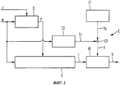
Для определения позиции поршня реальной, электрогидравлической системы рулевого управления предусмотрено построение детализированной нелинейной или упрощенной линейной параллельной модели, которая показана на фиг.2 US 2007/0124038 А1. При этом блок, обозначенный на фиг.2 ссылочным номером 19, представляет собой параллельную модель, которая охватывает детализированную нелинейную схему реальной динамики системы или упрощенное линейное описание. В качестве единственного входного сигнала для параллельной модели 19 предусмотрено изменяющееся во времени заданное управляющее воздействие - обозначенное ссылочным номером 20 - для контура системы управления приводным механизмом, которое сохраняется в запоминающем устройстве компьютерной системой управления полетом. Единственный выходной сигнал параллельной модели 19 обозначен ссылочным номером 29 и описывает полученную позицию приводного элемента поршня, которая изменяется во времени.To determine the position of the piston of a real, electro-hydraulic steering system, a detailed non-linear or simplified linear parallel model is constructed, which is shown in FIG. 2 of US 2007/0124038 A1. In this case, the block indicated in FIG. 2 by the reference number 19 is a parallel model that encompasses a detailed nonlinear diagram of the real dynamics of the system or a simplified linear description. As a single input signal for the parallel model 19, a predetermined time-varying control action — indicated by a
В этой связи на фиг.1 данного описания показана упрощенная блок-схема традиционного устройства V для генерирования остатка r.In this regard, figure 1 of this description shows a simplified block diagram of a conventional device V for generating residue r.
При этом традиционное устройство V с фиг.1 соответствует обобщенному изображению на фиг.4 US 2007/0124038 А1, для того, чтобы лучше представить недостатки известного уровня техники.Moreover, the traditional device V of FIG. 1 corresponds to the generalized image in FIG. 4 of US 2007/0124038 A1, in order to better present the disadvantages of the prior art.
На фиг.1 ссылочным знаком z обозначена величина помех, которая отображает внешние помехи в системе S.In Fig. 1, a reference sign z denotes an amount of interference that reflects external interference in system S.
Система S в качестве входного параметра имеет величину w управляющего воздействия, а на выходе представляет выходной параметр у системы. Система S представляет собой, например, реальную электрогидравлическую систему рулевого управления, а выходной параметр у системы соответствует измеренному перемещению приводного элемента поршня системы рулевого управления. Для получения определенного значения выходного параметра у системы параллельно системе S расположена модель SM системы.The system S as an input parameter has a value w of the control action, and at the output it represents the output parameter of the system. System S is, for example, a real electro-hydraulic steering system, and the output parameter of the system corresponds to the measured movement of the piston drive element of the steering system. To obtain a certain value of the output parameter of the system, a model of the SM system is located parallel to system S.
Ключевым моментом способа оценки, описанного в US 2007/0124038 А1, по существу, является параллельная модель системы или модель процесса, которая в виде математического описания оптимально аппроксимирует исходные значения процесса или системы и их параметризацию. Единственным входным сигналом модели SM системы является сигнал, идентичный входному сигналу системы S, который представляет собой величину управляющего воздействия или заданное значение w управляющего воздействия. В соответствии с выбранными начальными значениями и параметризированной динамикой системы определенной модели системы определяется оценочный выходной параметр ![]()
![]()
![]()
![]()
При применении решения, схематически показанного на фиг.1 и известного из US 2007/0124038 А1, к конкретной задаче обнаружения ошибок, связанных с переходными процессами, дрейфом или колебаниями, электрогидравлической системы рулевого управления могут возникнуть следующие проблемы: не удается сделать удовлетворительный выбор надежного и вместе с тем высокочувствительного порогового значения обнаружения для остатка r, поскольку могут возникать внешние помехи, обозначенные ссылочным знаком z, которые действуют на систему S, однако, не отображаются моделью SM системы. Эти внешние помехи возникают в электрогидравлической системе рулевого управления, в частности, из-за аэродинамических сил, которые во время полета действуют на приводную подвижную плоскость и создают механическую нагрузку для приводной системы, например, вследствие нестационарных потоков, которые возникают в результате таких единовременных явлений, как порыв ветра, гармонических помех вследствие периодических вихревых срывов или влияния гибкости окружающей конструкции или случайных помех, в частности, шумовых помех, по причине аэродинамического воздействия турбулентности. Еще одна причина недостаточной возможности устанавливать пороговое значение обнаружения заключается в постоянном наложении измеренного уровня шума на измерение позиции приводного элемента, которая используется в качестве выходного параметра у системы, из-за наличия сенсорных элементов в измерительных приборах, например, датчика позиции на приводном элементе штока поршня.When applying the solution schematically shown in FIG. 1 and known from US 2007/0124038 A1 to the specific task of detecting errors associated with transients, drifts or vibrations of the electro-hydraulic steering system, the following problems may arise: it is not possible to make a satisfactory choice of a reliable and at the same time, a highly sensitive detection threshold for the remainder r, since external interference, denoted by z, can occur, which act on the system S, however, do not display I model SM system. These external disturbances occur in the electro-hydraulic steering system, in particular, due to the aerodynamic forces that act on the drive moving plane during flight and create a mechanical load for the drive system, for example, due to unsteady flows that arise as a result of such one-time phenomena, like a gust of wind, harmonic interference due to periodic vortex disruptions or the influence of the flexibility of the surrounding structure or accidental interference, in particular noise interference, due to air the dynamic effects of turbulence. Another reason for the insufficient ability to set the detection threshold value is the constant imposition of the measured noise level on the measurement of the position of the drive element, which is used as the output parameter of the system, due to the presence of sensor elements in measuring devices, for example, a position sensor on the drive element of the piston rod .
Кроме того, следствием высокодинамичных изменений величины w управляющего воздействия при наличии помех является очень быстрый, внезапный рост остатка r.In addition, the result of highly dynamic changes in the value of w of the control action in the presence of interference is a very rapid, sudden increase in the remainder r.
Процесс или система S изменяется также вследствие изменений параметров или краевых условий, например, скорости полета, высоты полета, углов атаки и рыскания, температуры, характеристик гидравлической среды приводного элемента и т.п. во время эксплуатации или полета. Эти изменения оказывают влияние на ответное поведение системы S и тем самым на собственную динамику системы S. Они не отображаются параллельной моделью SM процесса или системы.The process or system S also changes due to changes in parameters or boundary conditions, for example, flight speed, flight altitude, angle of attack and yaw, temperature, hydraulic characteristics of the drive element, etc. during operation or flight. These changes affect the response behavior of the system S and, thus, the intrinsic dynamics of the system S. They are not displayed by the parallel model SM of the process or system.
При этом начальные значения процесса или системы S при практических применениях могут быть только аппроксимированы при помощи модели. Инициированные таким образом отклонения в реакции модели SM системы, а также влияние пренебрегаемой и неизвестной динамики в решении, известном из US 2007/0124038 А1, остаются некорректированными.In this case, the initial values of the process or system S in practical applications can only be approximated using the model. Deviations thus initiated in the reaction of the SM system model, as well as the effect of neglected and unknown dynamics in the solution known from US 2007/0124038 A1, remain uncorrected.
Без принятия дополнительных мер это приводит к нежелательному появлению составляющей сигнала остатка, которая существенно затрудняет очень чувствительную настройку порогового значения для обнаружения ошибок без ограничения контролируемой полосы частот.Without additional measures, this leads to an undesirable appearance of a residual signal component, which substantially complicates the very sensitive adjustment of the threshold value for error detection without limiting the monitored frequency band.
В US 2007/0124038 А1 (фиг.2) для генерирования остатков путем получения значений разности между изменяющимися во времени величинами измеренной позиции приводного элемента 22 поршня и выходного параметра 29 параллельной модели предусмотрен блок 21 вычитания. Его выходной сигнал 24 соответствует полученному остатку. Далее ссылочным номером 23 обозначен модуль, предназначенный для анализа остатка с целью обнаружения ошибок.In US 2007/0124038 A1 (FIG. 2), a subtraction unit 21 is provided for generating residues by obtaining the difference between the time-varying values of the measured position of the piston drive element 22 and the output parameter 29 of the parallel model. Its output signal 24 corresponds to the received remainder. Next, reference numeral 23 denotes a module for analyzing the remainder in order to detect errors.
Аналитический модуль 23 сравнивает остаток 24 с предварительно определенным пороговым значением и считает каждое превышение этого порогового значения. После предварительно установленного количества сосчитанных превышений предварительно установленного порогового значения констатируется случай наличия колебательной ошибки, и выходной сигнал 26 принимает положительное логическое значение для индикации этой ошибки.The analytic module 23 compares the remainder 24 with a predetermined threshold value and counts each excess of this threshold value. After a predetermined number of counted excesses of the preset threshold value, the case of the presence of an oscillatory error is detected, and the output signal 26 takes a positive logical value to indicate this error.
Для того чтобы обеспечить определенную эффективность аналитического модуля 23, он имеет последовательное соединение с частотно-избирательным банком 27 фильтров, и подсоединенным компараторным блоком 25 для каждой отдельной полосы частот остатка 24. Частотно-избирательный банк 27 фильтров состоит из параллельно включенных попоено-пропускающих фильтров, предназначенных для спектрального разделения остатка 24 на предварительно установленные полосы частот. При этом ссылочным номером 28 обозначен вектор спектральных составляющих остатка 24 в полосах частот, установленных частотно-избирательным банком 27 фильтров.In order to ensure a certain efficiency of the analytical module 23, it has a serial connection with a frequency-selective filter bank 27, and a connected
Кроме того, компараторный блок 25 содержит определенный канал для каждой составляющей вектора 28, в котором соответствующая составляющая сравнивается с предварительно определенным пороговым значением. В каждом канале при помощи счетчика фиксируется превышение. Если количество зафиксированных превышений в канале превосходит предварительно определенный предел, констатируется случай наличия колебательной ошибки, который отображается при помощи выходного сигнала 28.In addition, the
При применении этого решения, известного из US 2007/0124038 А1, к конкретной задаче обнаружения системных ошибок электрогидравлической системы рулевого управления воздушного судна могут возникнуть следующие проблемы: определение надежного и вместе с тем высокочувствительного порогового значения обнаружения для остатка не удается в достаточной степени, поэтому обеспечивается лишь ограниченная эффективность функции контроля системы рулевого управления. Причина этого заключается, в частности, в том, что высокодинамичные изменения величины управляющего воздействия или заданного значения управляющего воздействия при наличии помех постоянно обуславливают очень быстрый и внезапный рост остатка. Эти изменения могут возникать, в частности, во время полета в турбулентной атмосфере, в результате реактивного поведения гибких конструкций или под действием периодических вихревых срывов. Кроме того, собственный измеряемый уровень шума системы может дополнительно усиливать эти вредные эффекты. Для того чтобы в соответствующих установленных полосах частот исключить подачу ложных сигналов ошибки, приходится, соответственно, повышать пороговые значения обнаружения, а также увеличивать количество необходимых циклов подтверждения. В результате этого существенно уменьшается чувствительность обнаружения незатухающих колебаний, возникающих вследствие системных ошибок, а также увеличивается время распознавания ошибки аналитическим модулем. Это относится, в частности, к таким системным ошибкам, при которых колебательная составляющая накладывается на номинальный низкочастотный выходной сигнал системы.When applying this solution, known from US 2007/0124038 A1, to the specific task of detecting system errors of an aircraft electro-hydraulic steering system, the following problems may arise: the determination of a reliable and at the same time highly sensitive detection threshold value for the remainder fails to a sufficient degree, therefore, it is ensured only limited effectiveness of the steering system control function. The reason for this is, in particular, that highly dynamic changes in the magnitude of the control action or the set value of the control action in the presence of interference constantly lead to a very fast and sudden increase in the remainder. These changes can occur, in particular, during flight in a turbulent atmosphere, as a result of reactive behavior of flexible structures or under the action of periodic vortex disruptions. In addition, the system's own measurable noise level can further enhance these detrimental effects. In order to prevent the generation of false error signals in the corresponding frequency bands, it is necessary to increase the detection thresholds, as well as increase the number of necessary confirmation cycles. As a result of this, the detection sensitivity of undamped oscillations arising due to system errors is significantly reduced, and the error recognition time of the analytical module is also increased. This applies, in particular, to such systemic errors in which the oscillatory component is superimposed on the nominal low-frequency output signal of the system.
Еще одна причина ограниченной эффективности функции контроля системы рулевого управления заключается во взаимных помехах между соседними диапазонами частот, поскольку технически сложно реализовать точное разделение. Такие взаимные помехи в случае различных пороговых значений могут вызывать многократные ложные срабатывания.Another reason for the limited effectiveness of the steering system monitoring function is the mutual interference between adjacent frequency ranges, since it is technically difficult to implement precise separation. Such mutual interference in the case of different threshold values can cause multiple false alarms.
Кроме того, может иметь место неточность определения границ верхней полосы частот в комбинации с соответствующими твердо установленными пороговыми значениями, что связано, в частности, с динамическим реактивным поведением конструкции. Это оказывает непосредственное негативное влияние на распознавание ошибок в верхнем диапазоне частот. При применении метода счета, известного из US 2007/0124038 А1, распознавание ошибок ограничено обнаружением колебательных ошибок системы управления. Возможность распространения на другие сценарии ошибок, в частности, ошибок, связанных с переходными параметрами или ползучестью, в принципе исключается по методическим причинам. Это приводит к необходимости использовать для контроля современных систем управления параллельную установку и оснащение различными специфическими устройствами для распознавания ошибок. В целом, система, предложенная в US 2007/0124038 А1 для анализа остатка, существенно затрудняет установку чувствительного порогового значения для обнаружения ошибок в широком диапазоне без ограничения контролируемой полосы частот.In addition, there may be an inaccuracy in determining the boundaries of the upper frequency band in combination with the corresponding firmly established threshold values, which is associated, in particular, with the dynamic reactive behavior of the structure. This has a direct negative effect on the recognition of errors in the upper frequency range. When applying the counting method known from US 2007/0124038 A1, error recognition is limited to detecting vibrational errors of the control system. The possibility of propagating errors to other scenarios, in particular, errors associated with transient parameters or creep, is, in principle, excluded for methodological reasons. This leads to the need to use for monitoring modern control systems parallel installation and equipping with various specific devices for error recognition. In general, the system proposed in US 2007/0124038 A1 for residue analysis makes it difficult to set a sensitive threshold for detecting errors over a wide range without limiting the monitored frequency band.
Раскрытие изобретенияDisclosure of invention
В соответствии с вышеизложенным задачей настоящего изобретения является обеспечение анализа остатка для обнаружения системных ошибок, в частности, ошибок, связанных с переходными процессами, дрейфом или колебаниями, в поведении системы воздушного судна, который не содержит недостатков, описанных выше.In accordance with the foregoing, it is an object of the present invention to provide a residual analysis for detecting system errors, in particular errors associated with transients, drift or fluctuations, in the behavior of an aircraft system that does not contain the drawbacks described above.
В соответствии с изобретением эта задача решена при помощи устройства с признаками, указанными в пункте 1 формулы изобретения, и/или при помощи способа с признаками, указанными в пункте 14 формулы изобретения.In accordance with the invention, this problem is solved by using a device with the features specified in
При этом предлагается устройство для анализа остатка с целью обнаружения ошибок системы, которая на входе получает изменяющуюся во времени величину управляющего воздействия и величину помехи, отображающую внешние помехи, а на выходе представляет выходной параметр системы, при этом указанное устройство содержит:At the same time, a device is proposed for analyzing the remainder in order to detect system errors, which at the input receives a time-varying amount of control action and an interference value representing external noise, and at the output it represents the output parameter of the system, while this device contains:
- устройство для генерирования остатка в зависимости по меньшей мере от величины управляющего воздействия и выходного параметра системы;- a device for generating a residue, depending at least on the magnitude of the control action and the output parameter of the system;
- компараторный блок для обеспечения результатов анализа путем сравнения остатка с установленным пороговым значением;- a comparator unit for providing analysis results by comparing the remainder with a set threshold value;
- первый блок для обеспечения постоянной составляющей порогового значения;- the first block to provide a constant component of the threshold value;
- второй блок для обеспечения адаптивной составляющей порогового значения в зависимости по меньшей мере от изменяющейся во времени величины управляющего воздействия; и- the second unit to provide an adaptive component of the threshold value depending on at least the time-varying amount of control action; and
- третий блок для обеспечения порогового значения путем объединения постоянной составляющей порогового значения с адаптивной составляющей порогового значения.- a third unit for providing a threshold value by combining a constant component of the threshold value with an adaptive component of the threshold value.
Указанные с первого по третий блок, а также компараторный блок можно использовать в виде аппаратного обеспечения или также в виде программного обеспечения. При использовании в виде аппаратного обеспечения соответствующий блок может быть выполнен в виде компьютера или микропроцессора, узла или также части системы, например, в виде компьютерной системы. При использовании в виде программного обеспечения соответствующий блок может быть выполнен в виде компьютерного программного продукта, функции, стандартной программы, части программного кода или в виде исполняемого объекта.The first to third blocks as well as the comparator block can be used in the form of hardware or also in the form of software. When used in the form of hardware, the corresponding unit can be made in the form of a computer or microprocessor, a node, or also part of a system, for example, in the form of a computer system. When used in the form of software, the corresponding block can be made in the form of a computer program product, function, standard program, part of the program code, or as an executable object.
Предлагается также воздушное судно, содержащее по меньшей мере одно вышеописанное устройство.An aircraft is also provided comprising at least one of the above devices.
Кроме того, предлагается способ анализа остатка для обнаружения системных ошибок в поведении системы, которая получает на входе изменяющуюся во времени величину управляющего воздействия и величину помех, отображающую внешние помехи, а на выходе представляет выходной параметр системы, при этом указанный способ включает следующие операции:In addition, a method for analyzing the remainder is proposed for detecting system errors in the behavior of the system, which receives a control variable and an interference value at the input that reflects external noise, and the output represents the output parameter of the system, while this method includes the following operations:
- генерирование остатка в зависимости по меньшей мере от величины управляющего воздействия и выходного параметра системы;- generating a residue, depending at least on the magnitude of the control action and the output parameter of the system;
- обеспечение постоянной составляющей порогового значения;- providing a constant component of the threshold value;
- обеспечение адаптивной составляющей порогового значения в зависимости по меньшей мере от изменяющейся во времени величины управляющего воздействия;- providing an adaptive component of the threshold value, depending at least on the time-varying amount of control action;
- обеспечение порогового значения путем объединения постоянной составляющей порогового значения с адаптивной составляющей порогового значения; и- providing a threshold value by combining a constant component of the threshold value with an adaptive component of the threshold value; and
- сравнение остатка с представленным пороговым значением для обеспечения результата анализа.- comparison of the balance with the presented threshold value to ensure the result of the analysis.
Предлагается также компьютерный программный продукт, использование которого для устройства с программным управлением обеспечивает осуществление вышеописанного способа анализа остатка для обнаружения системных ошибок в поведении какой-либо системы.A computer software product is also proposed, the use of which for a program-controlled device provides the implementation of the method for analyzing the remainder described above to detect system errors in the behavior of any system.
Достоинством настоящего изобретения является надежный анализ остатка, при помощи которого можно обнаруживать наличие системных ошибок, в частности, ошибок, связанных с переходными процессами, ползучестью, незатухающими колебаниями или осцилляциями в какой-либо системе воздушного судна, в частности, в электрогидравлической системе рулевого управления.An advantage of the present invention is a reliable residue analysis, with which it is possible to detect the presence of system errors, in particular errors associated with transients, creep, undamped oscillations or oscillations in any aircraft system, in particular, in an electro-hydraulic steering system.
При этом согласно изобретению можно с высокой надежностью производить обнаружение вышеуказанных системных ошибок и, в частности, исключать ложные показания, благодаря применению адаптивного порогового значения обнаружения согласно изобретению.Moreover, according to the invention, it is possible to detect the above system errors with high reliability and, in particular, to eliminate false readings by using the adaptive detection threshold value according to the invention.
Эта высокая достоверность подтверждена при программно-аппаратном тестировании реальной системы рулевого управления, результаты которого опубликованы в докторской диссертации Sachs, Helge: "Fault Investigation and Robust Failure Detection of Oscillatory Aircraft Actuation Systems Using Analytical Redundancy", Hamburg, Hamburg University of Technology, Aircraft Systems Engineering M-7.This high reliability was confirmed by software and hardware testing of a real steering system, the results of which are published in a doctoral dissertation by Sachs, Helge: "Fault Investigation and Robust Failure Detection of Oscillatory Aircraft Actuation Systems Using Analytical Redundancy", Hamburg, Hamburg University of Technology, Aircraft Systems Engineering M-7.
При этом согласно изобретению высокодинамичные изменения заданного значения управляющего воздействия или величины управляющего воздействия воспроизводятся непосредственно путем адаптации порогового значения за счет адаптивной составляющей порогового значения. Таким образом, учитывается также динамическая реакция системы на помехи, которые могут возникать во время полета в турбулентной атмосфере, в результате реактивного поведения гибких конструкций или периодических вихревых срывов. В частности, благодаря этому, согласно изобретению удается обеспечить надежное и быстрое обнаружение системных ошибок, в которых колебательная составляющая накладывается на номинальный выходной низкочастотный сигнал системы.Moreover, according to the invention, highly dynamic changes in the set value of the control action or the magnitude of the control action are reproduced directly by adapting the threshold value due to the adaptive component of the threshold value. Thus, the dynamic response of the system to interference that may occur during flight in a turbulent atmosphere as a result of reactive behavior of flexible structures or periodic vortex disruptions is also taken into account. In particular, due to this, according to the invention, it is possible to provide reliable and fast detection of system errors in which the oscillating component is superimposed on the nominal output low-frequency signal of the system.
Кроме того, ожидаемый собственный измеряемый уровень шума системы учитывается отдельно за счет постоянной составляющей порогового значения, которая предпочтительно устанавливается равной минимальному значению.In addition, the expected intrinsic measurable noise level of the system is taken into account separately due to the constant component of the threshold value, which is preferably set equal to the minimum value.
Благодаря прямому учету влияния изменяющегося во времени заданного значения управляющего воздействия согласно изобретению, больше не требуется отображать амплитуды, которые имеют место при нормальном режиме эксплуатации, при помощи пороговых значений обнаружения. Таким образом, для результирующих амплитуд ошибок можно всегда использовать во всех областях спектра минимальный предел ошибки, который ограничен только измерительной аппаратурой, которой оснащен процесс.Due to the direct consideration of the influence of the time-varying set value of the control action according to the invention, it is no longer necessary to display the amplitudes that occur during normal operation using threshold detection values. Thus, for the resulting error amplitudes, the minimum error limit can always be used in all regions of the spectrum, which is limited only by the measuring equipment with which the process is equipped.
Кроме того, благодаря исключению метода счета, известного из US 2007/0124038 А1, согласно изобретению можно существенно уменьшить или свести к нулю время подтверждения. В частности, таким образом, значительно снижается общее время распознавания ошибки, связанной с незатухающими колебаниями с большой длительностью периода.In addition, by eliminating the counting method known from US 2007/0124038 A1, according to the invention, the confirmation time can be significantly reduced or reduced to zero. In particular, in this way, the overall error recognition time associated with continuous wave oscillations with a long period is significantly reduced.
Кроме того, исключение традиционного метода счета позволяет обеспечивать обнаружение системных ошибок, которые не приводят к колебаниям, в частности, позиции приводного элемента поршня или поверхности управления. Вследствие этого можно обнаруживать также системные ошибки, связанные с переходными процессами и ползучестью. При этом для распознавания ошибок можно существенно уменьшить оснащение различными специфическими устройствами.In addition, the exclusion of the traditional counting method allows the detection of system errors that do not lead to fluctuations, in particular, the position of the piston drive element or the control surface. As a result of this, system errors associated with transients and creep can also be detected. Moreover, to recognize errors, it is possible to significantly reduce the equipment with various specific devices.
Одной из задач настоящего изобретения является обеспечение генерирования остатков для обнаружения ошибок, связанных с переходными процессами, дрейфом или колебаниями, в поведении системы воздушного судна, которое не содержит вышеуказанных недостатков.One of the objectives of the present invention is the provision of generating residuals for detecting errors associated with transients, drift or fluctuations in the behavior of the aircraft system, which does not contain the above disadvantages.
Эта задача решена согласно изобретению при помощи устройства с признаками пунктов формулы изобретения и/или при помощи способа с признаками пунктов формулы изобретения.This problem is solved according to the invention using a device with features of the claims and / or using a method with features of the claims.
В соответствии с этим предлагается устройство для генерирования остатков с целью обнаружения ошибок, связанных с переходными процессами, дрейфом или колебаниями, в поведении системы воздушного судна, которая получает на входе заданное управляющее воздействие и величину помех, отображающую внешние помехи, а на выходе представляет выходной параметр системы, при этом указанное устройство содержит:In accordance with this, a device is proposed for generating residuals in order to detect errors associated with transients, drift or oscillations in the behavior of the aircraft system, which receives a predetermined control action and an amount of interference representing external interference at the input and represents an output parameter at the output system, while the specified device contains:
- первое средство с моделью системы для отображения контролируемой системы, которое получает на входе величину управляющего воздействия, величину обратной связи наблюдателя и величину помех модели и представляет на выходе оценочный выходной параметр системы, в зависимости от указанных параметров;- the first tool with a system model for displaying the controlled system, which receives the input of the control action, the amount of feedback from the observer and the amount of interference of the model and represents the estimated output parameter of the system, depending on the specified parameters;
- второе средство для получения остатка в виде разности между выходным параметром системы и оценочным выходным параметром системы;- second means for obtaining the remainder in the form of a difference between the output parameter of the system and the estimated output parameter of the system;
- третье средство с обратной связью наблюдателя, которое получает на входе остаток и представляет на выходе величину обратной связи наблюдателя, в зависимости от указанного остатка, для динамической корректировки модели системы таким образом, чтобы оценочный выходной параметр следовал за выходным параметром системы; и- the third means with observer feedback, which receives the remainder at the input and presents the output of the observer feedback, depending on the specified remainder, for dynamically adjusting the system model so that the estimated output parameter follows the output parameter of the system; and
- четвертое средство с моделью помех, которое получает на входе остаток и на выходе представляет величину помех модели, в зависимости от указанного остатка, для отображения влияния внешних помех на модель системы.- the fourth means with an interference model, which receives the remainder at the input and at the output represents the model interference value, depending on the specified remainder, to display the effect of external interference on the system model.
Каждое из указанных с первого по четвертое средств можно применять в виде аппаратного обеспечения или также в виде программного обеспечения. При применении в виде аппаратного обеспечения соответствующее средство может быть выполнено в виде устройства, например, компьютера или микропроцессора, узла или также части системы, например, в виде компьютерной системы. При применении в виде программного обеспечения соответствующее средство может быть выполнено в виде компьютерного программного продукта, функции, стандартной программы, части программного кода или в виде исполняемого объекта.Each of the first to fourth means can be used in the form of hardware or also in the form of software. When applied in the form of hardware, the corresponding means can be made in the form of a device, for example, a computer or microprocessor, a node or also part of a system, for example, in the form of a computer system. When applied in the form of software, the corresponding tool can be performed in the form of a computer program product, function, standard program, part of the program code, or as an executable object.
Кроме того, предлагается воздушное судно, содержащее по меньшей мере одно из вышеописанных устройств.In addition, an aircraft is proposed comprising at least one of the above devices.
Далее предлагается способ генерирования остатка для обнаружения ошибок, связанных с переходными процессами, дрейфом или колебаниями, в поведении системы воздушного судна. Система получает на входе заданное управляющее воздействие и величину помех, отображающую внешние помехи, и представляет на выходе выходной параметр системы. Такой способ согласно изобретению включает следующие операции:The following provides a method for generating a residual for detecting transient, drift or oscillation errors in the behavior of an aircraft system. The system receives at the input a predetermined control action and an interference value representing external interference, and represents the output parameter of the system at the output. Such a method according to the invention includes the following operations:
- обеспечение модели системы для отображения контролируемой системы, которая на входе получает величину управляющего воздействия, величину обратной связи наблюдателя и величину помех модели и на выходе представляет оценочный выходной параметр системы, в зависимости от указанных параметров;- providing a model of the system for displaying the controlled system, which at the input receives the magnitude of the control action, the amount of feedback from the observer and the amount of interference of the model and the output represents the estimated output parameter of the system, depending on the specified parameters;
- получение остатка в виде разности между выходным параметром системы и оценочным выходным параметром системы;- obtaining the remainder in the form of the difference between the output parameter of the system and the estimated output parameter of the system;
- обеспечение обратной связи наблюдателя, которая на входе получает остаток и на выходе представляет величину обратной связи наблюдателя, в зависимости от указанного остатка, для динамической корректировки модели системы, таким образом, чтобы оценочный выходной параметр системы следовал за выходным параметром системы;- providing the observer feedback, which receives the remainder at the input and at the output represents the amount of the observer feedback, depending on the indicated remainder, for dynamically adjusting the system model so that the estimated output parameter of the system follows the output parameter of the system;
иand
- обеспечение модели помех, которая на входе получает остаток и представляет на выходе величину помех модели, в зависимости от указанного остатка, для отображения влияния внешних помех на модель системы.- providing a model of interference, which receives the remainder at the input and represents the amount of model interference at the output, depending on the specified residue, to display the effect of external interference on the system model.
Кроме того, предлагается компьютерный программный продукт, использование которого для устройства с программным управлением обеспечивает осуществление вышеописанного способа генерирования остатка для обнаружения ошибок, связанных с переходными процессами, дрейфом или колебаниями, в поведении системы воздушного судна.In addition, a computer program product is proposed, the use of which for a device with program control provides the implementation of the above method of generating a residue to detect errors associated with transients, drift or fluctuations in the behavior of the aircraft system.
С первого по четвертое средства образуют, в частности, блок наблюдателя помех или наблюдателя помех.The first to fourth means form, in particular, a block of an interference observer or an interference observer.
Наблюдатель помех согласно изобретению определяет последующее поведение модели системы в соответствии с оценочным выходным параметром системы, например, в соответствии с положением поршня системы рулевого управления. Это обеспечивается путем определения соотношения остатка и внутреннего состояния модели системы посредством обратной связи наблюдателя. Для того чтобы аппроксимировать помехи для реального процесса или для реальной системы, в частности, посредством динамических воздушных нагрузок и измеренных уровней шума на модели системы, параллельно возврату наблюдателя создается модель помех. Приблизительное или оценочное действие помех, которое согласно изобретению отображается как величина помех модели, также соотносится с внутренними состояниями модели системы. Таким образом, наряду с последующим поведением системы в оценочном выходном параметре системы или на выходе наблюдателя помех дополнительно отображается непосредственное влияние внешних помех системы.The interference observer according to the invention determines the subsequent behavior of the system model in accordance with the estimated output parameter of the system, for example, in accordance with the position of the piston of the steering system. This is ensured by determining the ratio of the remainder and the internal state of the system model through the feedback of the observer. In order to approximate the interference for a real process or for a real system, in particular, through dynamic air loads and measured noise levels on a system model, an interference model is created in parallel with the return of the observer. The approximate or estimated effect of interference, which according to the invention is displayed as the amount of interference of the model, also correlates with the internal states of the model of the system. Thus, along with the subsequent behavior of the system, the direct influence of external interference of the system is additionally displayed in the estimated output parameter of the system or at the output of the interference observer.
Достоинство настоящего изобретения заключается в надежном генерировании остатка, при помощи которого можно обнаруживать наличие ошибки, в частности, ошибки, связанной с переходными процессами, дрейфом, ползучестью или колебаниями в системе воздушного судна. Затем осуществляется анализ путем сравнения остатка с предварительно установленным пороговым значением. При помощи решения согласно изобретению можно установить надежное и высокочувствительное пороговое значение остатка для обнаружения ошибки, что подтверждено при программно-аппаратном тестировании реальной системы рулевого управления, результаты которого опубликованы в докторской диссертации Sachs, Helge: "Fault Investigation and Robust Failure Detection of Oscillatory Aircraft Actuation Systems Using Analytical Redundancy", Hamburg, Hamburg University of Technology, Aircraft Systems Engineering M-7.An advantage of the present invention is the reliable generation of a residue with which it is possible to detect the presence of an error, in particular an error associated with transients, drift, creep or oscillations in the aircraft system. Then the analysis is carried out by comparing the remainder with a predetermined threshold value. Using the solution according to the invention, it is possible to set a reliable and highly sensitive threshold value for residual error detection, which is confirmed by software and hardware testing of a real steering system, the results of which are published in the doctoral dissertation of Sachs, Helge: "Fault Investigation and Robust Failure Detection of Oscillatory Aircraft Actuation Systems Using Analytical Redundancy ", Hamburg, Hamburg University of Technology, Aircraft Systems Engineering M-7.
При этом внешние помехи, которые оказывают влияние на процесс или систему, отображаются наблюдателем помех согласно изобретению в виде приближения. Такие внешние помехи или возмущения процесса возникают, по существу, из аэродинамических сил, которые действуют на приводную подвижную плоскость во время полета, в частности, в виде переходных помех в результате таких однократных событий, как порыв ветра, гармонических помех от периодических вихревых срывов или влияний гибкости окружающей конструкции или из случайных помех, в частности, турбулентности, и, согласно изобретению, не оказывают значительного влияния на остаток.In this case, external interference that affects the process or system is displayed by the interference observer according to the invention in the form of an approximation. Such external disturbances or process disturbances arise essentially from aerodynamic forces that act on the driving moving plane during flight, in particular, in the form of transient disturbances as a result of such single events as a gust of wind, harmonic interference from periodic vortex disruptions or influences the flexibility of the surrounding structure or from random interference, in particular turbulence, and, according to the invention, do not significantly affect the remainder.
Кроме того, постоянное наложение результата измерения позиции приводного элемента, который служит в качестве выходного параметра системы, на измеренный уровень шума (например, выраженный отношением сигнал/шум в датчике позиции на приводном элементе штока поршня) не оказывает существенного влияния на генерированный остаток.In addition, the constant superposition of the result of measuring the position of the drive element, which serves as the output parameter of the system, on the measured noise level (for example, expressed by the signal-to-noise ratio in the position sensor on the drive element of the piston rod) does not significantly affect the generated residue.
Как указано выше, система или процесс изменяется в результате изменений параметров или краевых условий во время работы. Примерами таких изменяющихся параметров являются скорость полета, высота полета, углы атаки и рыскания, температура, характеристики гидравлической среды приводного элемента и т.п. Эти изменения влияют на реактивное поведение и собственную динамику системы. Они также отображаются наблюдателем помех согласно изобретению в последующем принудительном поведении и поэтому не видны в остатке.As indicated above, the system or process changes as a result of changes in parameters or boundary conditions during operation. Examples of such changing parameters are flight speed, flight altitude, angle of attack and yaw, temperature, hydraulic fluid characteristics of the drive element, etc. These changes affect the reactive behavior and the system’s own dynamics. They are also displayed by the interference observer according to the invention in subsequent forced behavior and therefore are not visible in the remainder.
Различные начальные значения в системе и в модели системы также минимизируются за счет обратной связи наблюдателя. Поэтому они не оказывают дальнейшего влияния на генерированный остаток согласно изобретению.Different initial values in the system and in the system model are also minimized due to the feedback of the observer. Therefore, they do not further influence the generated residue according to the invention.
Если имеются или могут быть заранее надежно описаны другие измеряемые величины системы, модель системы может быть сокращена за счет этих элементов. Измеряемые величины представляются наблюдателю помех в качестве дополнительных входных параметров. Они выгодно повышают достоверность оценочного выходного параметра системы наблюдателя помех и дополнительно минимизируют остаток.If other measured values of the system are available or can be reliably described in advance, the system model can be reduced by these elements. Measured values are presented to the interference observer as additional input parameters. They advantageously increase the reliability of the estimated output parameter of the interference observer system and further minimize the remainder.
Если части процесса или системы жестко определены, они удаляются из наблюдателя помех. В этом случае редуцированный наблюдатель помех может быть сокращен до части процесса или системы, которая связана с не измеряемыми непосредственно и/или устойчивыми динамическими эффектами. Сокращение полного наблюдателя помех до редуцированного наблюдателя помех, интегрированного в стационарные уравнения системы, приводит к дополнительному повышению стабильности и тем самым к повышению быстродействия предлагаемого способа.If parts of a process or system are rigidly defined, they are removed from the interference observer. In this case, the reduced interference observer can be reduced to the part of the process or system that is associated with non-directly measurable and / or persistent dynamic effects. Reducing the total interference observer to a reduced interference observer integrated into the stationary equations of the system leads to an additional increase in stability and thereby to increase the speed of the proposed method.
В зависимых пунктах формулы изобретения описаны предпочтительные варианты осуществления и усовершенствования изобретения.The dependent claims describe preferred embodiments and improvements of the invention.
Согласно предпочтительному варианту осуществления первый блок выполнен с возможностью обеспечения постоянной составляющей порогового значения в зависимости от ожидаемого собственного измеряемого уровня шума системы.According to a preferred embodiment, the first unit is configured to provide a constant component of the threshold value depending on the expected intrinsic measured noise level of the system.
Согласно другому предпочтительному варианту осуществления первый блок выполнен с возможностью установления минимального значения составляющей порогового значения в зависимости от ожидаемого собственного измеряемого уровня шума системы.According to another preferred embodiment, the first block is configured to set a minimum value of a threshold value component depending on the expected intrinsic measured noise level of the system.
Согласно следующему предпочтительному варианту осуществления устройство для генерирования остатка содержит по меньшей мере модель системы для отображения контролируемой системы.According to a further preferred embodiment, the remainder generating device comprises at least a system model for displaying a monitored system.
Согласно еще одному предпочтительному варианту осуществления устройство для генерирования остатка содержит:According to another preferred embodiment, a residue generating device comprises:
- первое средство с моделью системы для отображения контролируемой системы, которое получает на входе величину управляющего воздействия, величину обратной связи наблюдателя и величину помех модели и представляет на выходе оценочный выходной параметр системы, в зависимости от указанных параметров;- the first tool with a system model for displaying the controlled system, which receives the input of the control action, the amount of feedback from the observer and the amount of interference of the model and represents the estimated output parameter of the system, depending on the specified parameters;
- второе средство для получения остатка в виде разности между выходным параметром системы и оценочным выходным параметром системы;- second means for obtaining the remainder in the form of a difference between the output parameter of the system and the estimated output parameter of the system;
- третье средство с обратной связью наблюдателя, которое получает на входе остаток и представляет на выходе величину обратной связи наблюдателя, в зависимости от указанного остатка, для динамической корректировки модели системы таким образом, чтобы оценочный выходной параметр системы следовал за выходным параметром системы; и- the third means with observer feedback, which receives the remainder at the input and presents the output of the observer feedback, depending on the specified remainder, for dynamically adjusting the system model so that the estimated output parameter of the system follows the output parameter of the system; and
- четвертое средство с моделью помех, которое получает на входе остаток и представляет на выходе величину помех модели, в зависимости от указанного остатка, для отображения влияния внешних помех на модель системы.- the fourth means with an interference model, which receives the remainder at the input and represents the model interference value at the output, depending on the specified remainder, to display the effect of external interference on the system model.
При соединении концепции генерирования адаптивного порогового значения в сочетании с редуцированным наблюдателем помех при проведении программно-аппаратного тестирования реальной системы рулевого управления доказано, что, таким образом, существенно возрастает эффективность распознавания ошибок. При этом за счет снижения порога обнаружения чувствительность повышается на 55-90%. Время реконфигурации системы после работы в неуправляемом режиме, когда подвижная плоскость бесконтрольно перемещается с максимальной скоростью в ее конечное положение, составляет только 1/15 от всего интервала времени, заданного для реконфигурации. Кроме того, результирующие динамические нагрузки на конструкцию значительно уменьшаются.When combining the concept of generating an adaptive threshold value in combination with a reduced interference observer during the hardware-software testing of a real steering system, it is proved that, thus, the efficiency of error recognition is significantly increased. At the same time, by lowering the detection threshold, the sensitivity increases by 55-90%. The system reconfiguration time after uncontrolled operation, when the moving plane moves uncontrolled at maximum speed to its final position, is only 1/15 of the entire time interval specified for reconfiguration. In addition, the resulting dynamic loads on the structure are significantly reduced.
Согласно другому предпочтительному варианту осуществления второй блок выполнен с возможностью обеспечения адаптивной составляющей порогового значения в зависимости от изменяющейся во времени величины управляющего воздействия и по меньшей мере от одного параметра состояния, который оценивается при помощи модели системы.According to another preferred embodiment, the second block is configured to provide an adaptive component of the threshold value depending on the time-varying amount of control action and at least one state parameter, which is estimated using a system model.
Согласно другому предпочтительному варианту осуществления второй блок выполнен с возможностью обеспечения адаптивной составляющей порогового значения в зависимости от изменяющейся во времени величины управляющего воздействия и по меньшей мере от одного представленного измеряемого параметра системы и/или по меньшей мере от одного параметра состояния, который оценивается при помощи модели системы.According to another preferred embodiment, the second block is configured to provide an adaptive component of the threshold value depending on the time-varying amount of control action and on at least one represented measured parameter of the system and / or at least one state parameter, which is estimated using the model system.
Согласно другому предпочтительному варианту осуществления третий блок выполнен с возможностью суммирования постоянной составляющей порогового значения и адаптивной составляющей порогового значения для обеспечения порогового значения.According to another preferred embodiment, the third block is adapted to sum the constant component of the threshold value and the adaptive component of the threshold value to provide a threshold value.
Согласно другому предпочтительному варианту осуществления компараторный блок устанавливает положительное логическое значение для результата анализа с целью отображения ошибки системы, если представленный остаток превышает представленное пороговое значение.According to another preferred embodiment, the comparator unit sets a positive logical value for the analysis result in order to display a system error if the presented remainder exceeds the presented threshold value.
Согласно другому предпочтительному варианту осуществления предусмотрен четвертый блок, который активирует компараторный блок после истечения предварительно установленного времени подтверждения.According to another preferred embodiment, a fourth unit is provided that activates the comparator unit after a predetermined confirmation time has elapsed.
Согласно другому предпочтительному варианту осуществления системная ошибка образуется как ошибка, связанная с переходным процессом, дрейфом или колебанием.According to another preferred embodiment, a system error is generated as an error associated with a transient, drift or oscillation.
Краткое описание чертежейBrief Description of the Drawings
Ниже приведено более подробное описание примеров осуществления изобретения со ссылками на прилагаемые чертежи, на которых представлены:Below is a more detailed description of embodiments of the invention with reference to the accompanying drawings, on which:
фиг.1 - упрощенная блок-схема примера осуществления традиционного устройства для генерирования остатков с целью обнаружения ошибок системы воздушного судна;figure 1 is a simplified block diagram of an example implementation of a traditional device for generating residues in order to detect errors of the aircraft system;
фиг.2 - упрощенная блок-схема первого примера осуществления устройства для анализа остатка с целью обнаружения системных ошибок в поведении системы воздушного судна;figure 2 is a simplified block diagram of a first embodiment of a device for analyzing the remainder in order to detect system errors in the behavior of the aircraft system;
фиг.3 - упрощенная блок-схема второго примера осуществления устройства для анализа остатков с целью обнаружения системных ошибок в поведении системы воздушного судна;figure 3 is a simplified block diagram of a second embodiment of a device for analyzing residues in order to detect system errors in the behavior of the aircraft system;
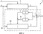
фиг.4 - упрощенная блок-схема первого примера осуществления устройства для генерирования остатков с целью обнаружения системных ошибок в поведении системы воздушного судна;4 is a simplified block diagram of a first embodiment of a device for generating residuals in order to detect system errors in the behavior of an aircraft system;
фиг.5 - упрощенная блок-схема второго примера осуществления устройства для генерирования остатков с целью обнаружения системных ошибок в поведении системы воздушного судна;5 is a simplified block diagram of a second embodiment of a device for generating residues in order to detect system errors in the behavior of the aircraft system;
фиг.6 - упрощенная блок-схема примера осуществления способа анализа остатка для обнаружения системных ошибок в поведении системы воздушного судна;6 is a simplified flowchart of an example implementation of a remainder analysis method for detecting system errors in aircraft system behavior;
фиг.7 - упрощенная блок-схема примера осуществления способа генерирования остатков с целью обнаружения системных ошибок в поведении системы воздушного судна; и7 is a simplified block diagram of an example implementation of a method of generating residuals in order to detect system errors in the behavior of the aircraft system; and
фиг.8-12 - схематические временные диаграммы, иллюстрирующие анализ остатка согласно изобретению для обнаружения системных ошибок в поведении системы воздушного судна.8-12 are schematic time diagrams illustrating a residue analysis according to the invention for detecting system errors in aircraft system behavior.
Если не указано иного, одинаковые или функционально одинаковые компоненты обозначены на чертежах одними и теми же ссылочными номерами.Unless otherwise indicated, the same or functionally identical components are indicated in the drawings by the same reference numbers.
Осуществление изобретенияThe implementation of the invention
На фиг.2 показана упрощенная блок-схема первого примера осуществления устройства Е анализа остатка r для обнаружения системных ошибок в поведении системы S воздушного судна. Система S получает на входе изменяющуюся во времени величину w управляющего воздействия и величину z помех, отображающую внешние помехи. В зависимости от указанных параметров система S представляет на выходе выходной параметр у системы. Устройство Е для анализа остатков содержит по меньшей мере одно устройство V для генерирования остатка r, компараторный блок KE, первый блок Е1, второй блок Е2 и третий блок Е3.FIG. 2 shows a simplified block diagram of a first embodiment of a residual analysis device r for detecting system errors in the behavior of an aircraft system S. The system S receives at the input a time-varying value w of the control action and an amount z of interference representing external interference. Depending on the specified parameters, the system S represents the output parameter of the system at the output. The device for analyzing residues contains at least one device V for generating residue r, a comparator block KE, a first block E1, a second block E2 and a third block E3.
Устройство V пригодно для генерирования остатка r, при этом устройство V генерирует остаток r в зависимости по меньшей мере от величины w управляющего воздействия и выходного параметра у системы.The device V is suitable for generating the remainder r, while the device V generates the remainder r depending on at least the value w of the control action and the output parameter of the system.
Устройство V выполнено, в частности, как показано в одном из примеров осуществления на фигурах 4 или 5.The device V is made, in particular, as shown in one of the embodiments in figures 4 or 5.
Компараторный блок KE представляет результат b анализа путем сравнения остатка r с представленным пороговым значением s.The comparator block KE represents the analysis result b by comparing the remainder r with the presented threshold value s.
Для обеспечения порогового значения s предусмотрены блоки Е1-Е3.To provide a threshold value s, blocks E1-E3 are provided.
При этом первый блок Е1 выполнен с возможностью обеспечения постоянной составляющей s0 порогового значения.In this case, the first block E1 is configured to provide a constant component s0 of the threshold value.
Второй блок Е2 выполнен с возможностью обеспечения адаптивной составляющей s1 порогового значения в зависимости по меньшей мере от изменяющейся во времени величины w управляющего воздействия.The second block E2 is configured to provide an adaptive component s1 of the threshold value, depending at least on the time-varying value w of the control action.
Третий блок Е3 выполнен с возможностью обеспечения порогового значения s путем объединения постоянной составляющей s0 порогового значения с адаптивной составляющей s1 порогового значения. В частности, третий блок Е3 суммирует постоянную составляющую s0 порогового значения и адаптивную составляющую s1 порогового значения для получения порогового значения s.The third block E3 is configured to provide a threshold value s by combining a constant component s0 of the threshold value with an adaptive component s1 of the threshold value. In particular, the third block E3 summarizes the constant component s0 of the threshold value and the adaptive component s1 of the threshold value to obtain the threshold value s.
Компараторный блок KE устанавливает положительное логическое значение для результата b анализа с целью отображения ошибки системы в том случае, если представленный остаток r превышает представленное пороговое значение s. Альтернативно этому результат b анализа может быть представлен в виде сигнала, например, в виде непрерывного сигнала, который может отображать оба возможных состояния (r>s и r≤s).The comparator block KE sets a positive logical value for the analysis result b in order to display the system error if the presented remainder r exceeds the presented threshold value s. Alternatively, the analysis result b can be represented as a signal, for example, as a continuous signal that can display both possible states (r> s and r≤s).
На фиг.3 показан второй пример осуществления устройства Е согласно изобретению для анализа остатка r с целью обнаружения системных ошибок в поведении системы S воздушного судна.Figure 3 shows a second embodiment of the device E according to the invention for analyzing the remainder r in order to detect system errors in the behavior of the aircraft system S.
Второй пример осуществления согласно фиг.3 содержит все признаки первого примера осуществления с фиг.2, которые не описываются во избежание повторений.The second embodiment of FIG. 3 contains all the features of the first embodiment of FIG. 2, which are not described to avoid repetition.
Во втором примере осуществления устройства Е согласно изобретению первый блок Е1 выполнен с возможностью обеспечения постоянной составляющей s0 порогового значения в зависимости от ожидаемого собственного измеряемого уровня шума mr системы S.In a second embodiment of the device E according to the invention, the first block E1 is configured to provide a constant component s0 of a threshold value depending on the expected intrinsic measured noise level mr of the system S.
При этом первый блок Е1 устанавливает постоянное пороговое значение s0 предпочтительно на минимальном уровне.In this case, the first block E1 sets a constant threshold value s0, preferably at a minimum level.
Далее согласно фиг.3 второй блок Е2 выполнен с возможностью обеспечения адаптивной составляющей s1 порогового значения в зависимости от изменяющейся во времени величины w управляющего воздействия, по меньшей мере от одного представленного измеряемого параметра тд системы S и/или от параметра zg состояния, который оценивается при помощи устройства V модели SM системы.Further, according to FIG. 3, the second block E2 is configured to provide an adaptive component s1 of the threshold value depending on the time-varying value w of the control action from at least one represented measured parameter td of the system S and / or from the state parameter zg, which is estimated at help device V model SM system.
Кроме того, устройство Е предпочтительно содержит четвертый блок Е4, который активирует компараторный блок KE после истечения предварительно установленного времени подтверждения. Для этого четвертый блок Е4 управляет компараторным блоком KE предпочтительно при помощи активирующего сигнала а.In addition, device E preferably comprises a fourth unit E4, which activates the comparator unit KE after a predetermined confirmation time has elapsed. To this end, the fourth unit E4 controls the comparator unit KE, preferably by means of an activation signal a.
Примеры устройства V для генерирования остатков r показаны на фигурах 4 и 5.Examples of device V for generating residuals r are shown in figures 4 and 5.
На фиг.4 представлена упрощенная блок-схема примера осуществления устройства V согласно изобретению для генерирования остатков с целью обнаружения системных ошибок, в частности, ошибок, связанных с переходными процессами, дрейфом или колебаниями, в поведении системы S воздушного судна.Figure 4 presents a simplified block diagram of an example implementation of a device V according to the invention for generating residues in order to detect system errors, in particular, errors associated with transients, drift or oscillations, in the behavior of the aircraft system S.
Устройство V для генерирования остатков с целью обнаружения ошибок, связанных с переходными процессами, дрейфом или колебаниями, в поведении системы S воздушного судна содержит первое средство 1, второе средство 2, третье средство 3 и четвертое средство 4. С первого по четвертое средства 1-4 образуют блок SB наблюдателя помех. Система S получает на входе заданное значение w управляющего воздействия и величину z помех, которая отображает внешние помехи, действующие на систему S. В зависимости от этого система представляет на выходе выходной параметр у системы. Система S представляет собой, например, электрогидравлическую систему рулевого управления воздушного судна, при этом выходной параметр у системы представляет собой измеренное перемещение приводного элемента поршня системы S рулевого управления, обеспечивающей позиционное управление.The device V for generating residuals in order to detect errors associated with transients, drift or fluctuations in the behavior of the aircraft system S contains the
Первое средство 1 содержит модель SM системы для отображения контролируемой системы S. Первое средство 1 получает на входе величину w управляющего воздействия, величину b обратной связи наблюдателя и величину ![]()
![]()
![]()
![]()
Второе средство 2 обеспечивает получение остатка r в виде разности между выходным параметром у системы и оценочным выходным параметром ![]()
![]()
Третье средство 3 выполнено в виде блока L обратной связи наблюдателя. Третье средство 3 получает на входе остаток r и в зависимости от полученного остатка r представляет на выходе величину bg обратной связи наблюдателя для динамической корректировки модели SM системы таким образом, чтобы оценочный выходной параметр ![]()
![]()
Далее четвертое средство 4 оснащено моделью ZM помех, которая получает на входе остаток r и в зависимости от него представляет на выходе величину ![]()
![]()
Блок L обратной связи наблюдателя предназначен, в частности, для динамической корректировки внутренних состояний модели SM системы, чтобы, таким образом, получить оценочный выходной параметр ![]()
![]()
На фиг.5 показан второй пример осуществления устройства V согласно изобретению для генерирования остатка r с целью обнаружения системных ошибок, в частности, ошибок, связанных с переходными процессами, дрейфом или колебаниями, в поведении системы S воздушного судна.5 shows a second embodiment of a device V according to the invention for generating a residual r for detecting system errors, in particular errors associated with transients, drift or oscillations, in the behavior of the aircraft system S.
Второй пример осуществления согласно фиг.5 содержит все признаки первого примера осуществления с фиг.4, которые не описываются еще раз во избежание повторений.The second embodiment of FIG. 5 contains all the features of the first embodiment of FIG. 4, which are not described again to avoid repetition.
Во втором примере осуществления устройства V согласно изобретению блок SB наблюдателя помех содержит матрицу L обратной связи наблюдателя для получения величины обратной связи наблюдателя. При этом коэффициенты матрицы L обратной связи наблюдателя определяются при помощи проекта регулятора параметров состояния. Проект регулятора параметров состояния получается, например, путем задания полюса, оптимального расчета регулятора, способа проектирования для расчета надежных обратных связей, линейной квадратичной оценки (LQE; Linear Quadratic Estimator) или нелинейных подходов.In a second embodiment of the device V according to the invention, the interference observer unit SB comprises an observer feedback matrix L for obtaining an observer feedback amount. In this case, the coefficients of the observer feedback matrix L are determined using the design of the state parameter regulator. The project of the state parameter regulator is obtained, for example, by setting the pole, optimal regulator calculation, design method for calculating reliable feedbacks, linear quadratic estimation (LQE; Linear Quadratic Estimator) or non-linear approaches.
Далее величина ![]()
![]()
![]()
![]()
Динамическая величина ![]()
![]()
![]()
![]()
![]()
![]()
![]()
![]()
![]()
![]()
![]()
![]()
![]()
![]()
![]()
![]()
![]()
![]()
![]()
![]()
![]()
![]()
![]()
![]()
На фиг.6 показана упрощенная блок-схема примера осуществления способа анализа остатка r для обнаружения системных ошибок в поведении системы S воздушного судна.FIG. 6 shows a simplified flowchart of an example implementation of a residual r analysis method for detecting system errors in the behavior of an aircraft system S.
Ниже приведено описание способа согласно изобретению при помощи упрощенной блок-схемы на фиг.6 со ссылками на упрощенную блок-схему на фиг.2. Пример осуществления способа согласно изобретению, показанный на фиг.6, включает следующие операции R1-R5:The following is a description of the method according to the invention using the simplified flowchart of FIG. 6 with reference to the simplified flowchart of FIG. 2. An example implementation of the method according to the invention, shown in Fig.6, includes the following operations R1-R5:
Операция R1:Operation R1:
Генерирование остатка r в зависимости по меньшей мере от величины w управляющего воздействия и выходного параметра у системы.The generation of the remainder r, depending at least on the value w of the control action and the output parameter of the system.
Операция R2:Operation R2:
Обеспечение постоянной составляющей s0 порогового значения.Providing a constant component s0 of the threshold value.
Операция R3:Operation R3:
Обеспечение адаптивной составляющей s1 порогового значения в зависимости по меньшей мере от изменяющейся во времени величины w управляющего воздействия.Providing the adaptive component s1 of the threshold value, depending at least on the time-varying value w of the control action.
Операция R4:Operation R4:
Обеспечение порогового значения s путем объединения, в частности, при помощи сложения, постоянной составляющей s0 порогового значения с адаптивной составляющей s1 порогового значения.Providing the threshold value s by combining, in particular, by adding, the constant component s0 of the threshold value with the adaptive component s1 of the threshold value.
Операция R5:Operation R5:
Сравнение остатка r с представленным пороговым значением s для обеспечения результата b анализа. Если остаток r превышает представленное пороговое значение s, констатируется системная ошибка системы S.Comparison of the remainder r with the presented threshold value s to ensure the result of the analysis b. If the remainder r exceeds the presented threshold value s, a system error of system S is detected.
На фиг.7 показана упрощенная блок-схема примера осуществления способа генерирования остатка r согласно изобретению для обнаружения системных ошибок, в частности, ошибок, связанных с переходными процессами, дрейфом или колебаниями, в поведении системы S воздушного судна, на вход которой поступает величина w управляющего воздействия и величина z помех, отображающая внешние помехи, а на выходе представляется выходной параметр у системы.7 shows a simplified flowchart of an example of a method for generating a residual r according to the invention for detecting system errors, in particular, errors associated with transients, drift or oscillations, in the behavior of the aircraft system S, to the input of which the value w of the control effects and the magnitude z of interference, reflecting external interference, and the output is the output parameter of the system.
Ниже приведено описание способа согласно изобретению, показанного на упрощенной блок-схеме на фиг.7 со ссылками на блок-схему на фиг.4. Пример осуществления способа, показанный на фиг.7, содержит следующие операции S1-S4.The following is a description of the method according to the invention shown in the simplified flowchart of FIG. 7 with reference to the flowchart of FIG. 4. An example implementation of the method shown in Fig.7, contains the following operations S1-S4.
Операция S1:Operation S1:
Обеспечение модели SM системы для отображения контролируемой системы S. Модель SM системы получает на входе величину w управляющего воздействия, величину bg обратной связи наблюдателя и величину z помех модели. В зависимости от указанных параметров модель SM системы представляет на выходе оценочный выходной параметр ![]()
![]()
Операция S2:Operation S2:
Получение остатка r в виде разности между выходным параметром у системы и оценочным выходным параметром ![]()
![]()
Операция S3:Operation S3:
Обеспечение обратной связи L наблюдателя, которая получает на входе остаток r и в зависимости от указанного остатка представляет на выходе величину bg обратной связи наблюдателя для динамической корректировки модели SM системы таким образом, чтобы оценочный выходной параметр ![]()
![]()
Операция S4:Operation S4:
Обеспечение модели ZM помех, которая получает на входе остаток r и в зависимости от указанного остатка представляет на выходе величину ![]()
![]()
При установленном наличии еще одного измеряемого параметра системы S число оценочных системных параметров в модели SM системы предпочтительно уменьшается на этот дополнительный измеряемый параметр, и этот дополнительный измеряемый параметр вводится непосредственно в модель SM системы в качестве дополнительного входного параметра.When it is established that there is one more measured parameter of the system S, the number of estimated system parameters in the SM model of the system is preferably reduced by this additional measured parameter, and this additional measured parameter is entered directly into the SM model of the system as an additional input parameter.
На фигурах 8-12 показаны схематические временные диаграммы, которые иллюстрируют анализ остатка r согласно изобретению для обнаружения системных ошибок FC в поведении системы S воздушного судна.Figures 8-12 are schematic timing diagrams that illustrate the analysis of the remainder r according to the invention for detecting system errors FC in the behavior of the aircraft system S.
В основе примера, показанного на фигурах 8-12, лежит система S, которая представляет собой систему рулевого управления с первым приводным элементом поршня и со вторым, резервным приводным элементом поршня и в которой управляющее воздействия первого приводного элемента поршня, используемого как первый приводной элемент, служит в качестве выходного сигнала y1 системы, а управляющее воздействие резервного второго приводного элемента поршня, используемого как второй приводной элемент, служит в качестве выходного сигнала y2 системы.The example shown in figures 8-12 is based on a system S, which is a steering system with a first piston drive element and a second, backup piston drive element and in which the control action of the first piston drive element used as the first drive element, serves as the output signal y1 of the system, and the control action of the backup second drive element of the piston used as the second drive element serves as the output signal y2 of the system.
При этом на фигуре 8 показана зависимость выходных сигналов y1 и y2 системы от времени. Далее на фигуре 9 показана зависимость величины z помех от времени. На фигуре 10 показаны зависимости от времени остатка r и порогового значения s согласно изобретению. Затем на фигурах 11 и 12 показана зависимость от времени результата b анализа, а также зависимость от времени управляющего сигнала msv, который генерируется в зависимости от результатов b анализа для выбора приводного элемента 1 или 2.Moreover, figure 8 shows the dependence of the output signals y1 and y2 of the system on time. Next, figure 9 shows the dependence of the value of z interference on time. Figure 10 shows the time dependence of the residue r and the threshold value s according to the invention. Then, figures 11 and 12 show the time dependence of the analysis result b, as well as the time dependence of the control signal msv, which is generated depending on the results of the analysis b to select the
Как указано выше, на фигуре 8 показана зависимость от времени выходных сигналов y1 и y2. В момент времени t=17 с выходные сигналы y1 и y2 системы резко возрастают в соответствии с заданным значением w управляющего воздействия.As indicated above, figure 8 shows the time dependence of the output signals y1 and y2. At time t = 17 s, the output signals y1 and y2 of the system increase sharply in accordance with the set value w of the control action.
Далее на фигуре 9 показана зависимость от времени величины z помех, соответствующей силе, которая посредством приводного элемента 1 или 2 нагружает приводную подвижную плоскость воздушного судна. Эта сила называется также аэродинамической или воздушной нагрузкой.The figure 9 further shows the time dependence of the magnitude z of the interference corresponding to the force which, by means of the driving
На фигуре 10 показана зависимость от времени остатка r и порогового значения s согласно изобретению. При этом фигура 10а является детальным изображением фрагмента фигуры 10 в момент времени t=17 с, когда согласно фигуре 8 имеет место скачкообразный рост величины w управляющего воздействия и, следовательно, выходных параметров y1 и y2 системы. Согласно изобретению пороговое значение s согласуется с заданным значением w управляющего воздействия, т.е. пороговое значение s согласуется со скачком заданного значения w управляющего воздействия и поэтому также имеет скачок (см. фиг.10а). В результате этого в момент времени t=17 с согласно фигуре 11 ошибка не обнаружена, поэтому в момент времени t=17 с b=0.Figure 10 shows the time dependence of the residue r and the threshold value s according to the invention. Moreover, figure 10a is a detailed image of a fragment of figure 10 at time t = 17 s, when according to figure 8 there is an abrupt increase in the value w of the control action and, therefore, the output parameters y1 and y2 of the system. According to the invention, the threshold value s is consistent with a predetermined value w of the control action, i.e. the threshold value s is consistent with a jump in the set value w of the control action and therefore also has a jump (see Fig. 10a). As a result of this, at time t = 17 s according to FIG. 11, no error was detected, therefore, at time t = 17 s b = 0.
В момент времени t=25 с, напротив, возникает системная ошибка FC, которая приводит колебаниям выходных сигналов y1 и y2 системы. Поскольку после этого момента времени t=25 с заданное значение w управляющего воздействия не изменяется, пороговое значение s также не изменяется. Вследствие этого в момент времени t=25 с остаток r превышает представленное пороговое значение s. Это подробно показано на фигуре 10b.At time t = 25 s, on the contrary, a system error FC arises, which leads to oscillations of the output signals y1 and y2 of the system. Since after this point in time t = 25 s, the set value w of the control action does not change, the threshold value s also does not change. As a result, at time t = 25 s, the remainder r exceeds the presented threshold value s. This is shown in detail in figure 10b.
В результате этого, как показано на фигуре 11, результат b анализа изменяется от 0 до 1, т.е., в момент времени t=25 с b=1.As a result of this, as shown in FIG. 11, the analysis result b varies from 0 to 1, i.e., at time t = 25 with b = 1.
Как показано на фигуре 12, после истечения времени BZ подтверждения, которое составляет, например, 2 с, управляющий сигнал msv изменяется от 1 до 0. Это изменение указывает, что происходит переключение с первого приводного элемента на второй приводной элемент. При этом в момент времени t=27 с реконфигурация и, следовательно, переключение системы S с первого приводного элемента на второй приводной элемент заканчивается.As shown in FIG. 12, after the confirmation time BZ, which is, for example, 2 s, has elapsed, the control signal msv changes from 1 to 0. This change indicates that there is a switchover from the first drive element to the second drive element. At the same time, at time t = 27 s, the reconfiguration and, therefore, the switching of the system S from the first drive element to the second drive element ends.
Согласно изобретению время подтверждения можно установить также равным 0, поскольку уже в момент времени t=25 с установлена необходимость переключения с приводного элемента 1 на приводной элемент 2.According to the invention, the confirmation time can also be set equal to 0, since already at the time t = 25 s the need for switching from the
Настоящее изобретение описано при помощи предпочтительных примеров осуществления, однако не ограничивается ими и может быть модифицировано различными способами.The present invention has been described using preferred embodiments, but is not limited to them and can be modified in various ways.
Перечень ссылочных обозначенийReference List
1 Первое средство1 First remedy
2 Второе средство2 Second remedy
3 Третье средство3 Third remedy
4 Четвертое средство4 Fourth remedy
а Активирующий сигналa Activating signal
BZ Время подтвержденияBZ Confirmation Time
b Результат анализаb Analysis result
bg Величина обратной связи наблюдателя или выходной сигнал обратной связи наблюдателяbg Observer feedback value or observer feedback output
А Системная матрица линейной модели SM системыA System matrix linear model of SM system
B Входная матрица линейной модели SM системыB Input matrix of the linear model of the SM system
C Выходная матрица линейной модели SM системыC The output matrix of the linear model of the SM system
E1 Первый блокE1 First block
E2 Второй блокE2 Second block
E3 Третий блокE3 Third block
E4 Четвертый блокE4 Fourth block
F Матрица величины помехF Interference matrix
KE Компараторный блокKE Comparator unit
K Корректирующая матрицаK Correction matrix
L Матрица обратной связи наблюдателяL Observer feedback matrix
mg Измеряемый параметрmg Measured parameter
mr Измеряемый уровень шумаmr measured noise level
R1-R5 ОперацияR1-R5 Operation
r Остатокr remainder
S СистемаS System
S1-S4 ОперацияS1-S4 Operation
SB Блок наблюдателя помехSB Block observer interference
SM Модель системыSM System Model
FC Системная ошибкаFC system error
w Величина управляющего воздействияw Control value
y Выходной параметр системыy System output parameter
![]()
![]()
z Величина помехz Interference value
zg Параметр состоянияzg Status parameter
![]()
![]()
ZM Модель помехZM Interference Model
![]()
![]()
Claims (23)
a) первое средство (1) с моделью (SM) системы для отображения контролируемой системы (S), которое получает на входе величину (w) управляющего воздействия, величину (bg) обратной связи наблюдателя и величину (
b) второе средство (2) для получения остатка (r) в виде разности между выходным параметром (y) системы и оценочным выходным параметром (y) системы;
c) третье средство (3) с обратной связью наблюдателя, которое получает на входе остаток (r) и представляет на выходе величину (bg) обратной связи наблюдателя, в зависимости от указанного остатка, для динамической корректировки модели (SM) системы таким образом, чтобы оценочный выходной параметр (
d) четвертое средство (4) с моделью (ZM) помех, которое получает на входе остаток (r) и представляет на выходе величину (
a) the first means (1) with a model (SM) of the system for displaying the controlled system (S), which receives at the input the magnitude (w) of the control action, the magnitude (bg) of the observer's feedback, and the magnitude (
b) second means (2) for obtaining the remainder (r) in the form of the difference between the output parameter (y) of the system and the estimated output parameter (y) of the system;
c) the third means (3) with observer feedback, which receives the remainder (r) at the input and presents the output (bg) of the observer feedback, depending on the specified remainder, for dynamically adjusting the model (SM) of the system so that estimated output parameter (
d) a fourth means (4) with a model of interference (ZM), which receives the remainder (r) at the input and represents the value (
a) обеспечение модели (SM) системы для отображения контролируемой системы (S), которая получает на входе величину (w) управляющего воздействия, величину (bg) обратной связи наблюдателя и величину помех (
b) получение остатка (r) в виде разности между выходным параметром (у) системы и оценочным выходным параметром (
c) обеспечение обратной связи наблюдателя, которая получает на входе остаток (r) и представляет на выходе величину (bg) обратной связи наблюдателя, в зависимости от указанного остатка, для динамической корректировки модели (SM) системы таким образом, чтобы оценочный выходной параметр (
d) обеспечение модели (ZM) помех, которая получает на входе остаток (r) и представляет на выходе величину (
a) providing a model (SM) of the system for displaying the controlled system (S), which receives the input value (w) of the control action, the value (bg) of the observer feedback and the amount of interference (
b) obtaining the remainder (r) in the form of the difference between the output parameter (s) of the system and the estimated output parameter (
c) providing feedback to the observer who receives the remainder (r) at the input and presents the value (bg) of the observer feedback, depending on the specified remainder, for dynamically adjusting the model (SM) of the system so that the estimated output parameter (
d) providing a model (ZM) of interference that receives the remainder (r) at the input and represents the value (
a) устройство (V) для генерирования остатка (r) в зависимости, по меньшей мере, от величины (w) управляющего воздействия и выходного параметра (y) системы;
b) компараторный блок (KE) для обеспечения результата (b) анализа путем сравнения остатка (r) с установленным пороговым значением (s);
c) первый блок (E1) для обеспечения постоянной составляющей (s0) порогового значения;
d) второй блок (Е2) для обеспечения адаптивной составляющей (s1) порогового значения в зависимости, по меньшей мере, от изменяющейся во времени величины (w) управляющего воздействия; и
e) третий блок (Е3) для обеспечения порогового значения (s) путем объединения постоянной составляющей (s0) порогового значения с адаптивной составляющей (s1) порогового значения.10. A device (E) for analyzing the remainder (r) in order to detect errors in the system (S), which receives at the input a time-varying amount of control action (w) and interference value (z) representing external interference, and at the output it represents the output system parameter (y) containing:
a) a device (V) for generating residue (r) depending at least on the amount (w) of the control action and the output parameter (y) of the system;
b) a comparator unit (KE) to provide the result (b) of the analysis by comparing the remainder (r) with the set threshold value (s);
c) a first block (E1) for providing a constant component (s0) of the threshold value;
d) a second block (E2) for providing the adaptive component (s1) of the threshold value, depending at least on the time-varying amount (w) of the control action; and
e) a third block (E3) for providing the threshold value (s) by combining the constant component (s0) of the threshold value with the adaptive component (s1) of the threshold value.
первое средство (1) с моделью (SM) системы для отображения контролируемой системы (S), которое получает на входе величину (w) управляющего воздействия, величину (bg) обратной связи наблюдателя и величину помех (z) модели и представляет на выходе оценочный выходной параметр (
второе средство (2) для получения остатка (r) в виде разности между выходным параметром (y) системы и оценочным выходным параметром (
третье средство (3) с обратной связью наблюдателя, которое получает на входе остаток (r) и представляет на выходе величину (bg) обратной связи наблюдателя, в зависимости от указанного остатка, для динамической корректировки модели (SM) системы таким образом, чтобы оценочный выходной параметр (
четвертое средство (4) с моделью (ZM) помех, которое получает на входе остаток (г) и представляет на выходе величину помех (z) модели, в зависимости от указанного остатка, для отображения влияния внешних помех на модель (SM) системы.15. The device according to claim 10, characterized in that the device (V) for generating residue (r) contains:
the first means (1) with a model (SM) of the system for displaying the controlled system (S), which receives at the input the magnitude (w) of the control action, the magnitude (bg) of the observer's feedback and the magnitude of the interference (z) of the model and presents the estimated output parameter (
second means (2) for obtaining the remainder (r) in the form of the difference between the output parameter (y) of the system and the estimated output parameter (
the third means (3) with observer feedback, which receives the remainder (r) at the input and represents the output (bg) of the observer feedback, depending on the indicated remainder, for dynamically adjusting the model (SM) of the system so that the estimated output parameter (
the fourth means (4) with a model of interference (ZM), which receives the remainder (g) at the input and presents the amount of interference (z) of the model, depending on the specified remainder, to display the effect of external interference on the model (SM) of the system.
a) генерирование остатка (r) в зависимости, по меньшей мере, от величины (w) управляющего воздействия и выходного параметра (y) системы;
b) обеспечение постоянной составляющей (s0) порогового значения;
c) обеспечение адаптивной составляющей (s1) порогового значения в зависимости по меньшей мере от изменяющейся во времени величины (w) управляющего воздействия;
а) обеспечение порогового значения (s) путем объединения постоянной составляющей (s0) порогового значения с адаптивной составляющей (s1) порогового значения; и
е) сравнение остатка (r) с представленным пороговым значением (s) для обеспечения результата (b) анализа. 23. The method of analyzing the remainder (r) to detect system errors in the behavior of the system (S), which receives at the input a time-varying amount of control action (w) and interference value (z) representing external noise, and the output parameter is the output parameter ( y) systems comprising the following operations:
a) generating a residue (r) depending at least on the amount (w) of the control action and the output parameter (y) of the system;
b) providing a constant component (s0) of the threshold value;
c) providing an adaptive component (s1) of the threshold value, depending at least on the time-varying amount (w) of the control action;
a) providing a threshold value (s) by combining a constant component (s0) of the threshold value with an adaptive component (s1) of the threshold value; and
e) comparing the remainder (r) with the presented threshold value (s) to ensure the result (b) of the analysis.
Applications Claiming Priority (5)
| Application Number | Priority Date | Filing Date | Title |
|---|---|---|---|
| US17323909P | 2009-04-28 | 2009-04-28 | |
| DE102009002682.7 | 2009-04-28 | ||
| DE102009002682A DE102009002682B4 (en) | 2009-04-28 | 2009-04-28 | Device and method for residual evaluation of a residual for detecting system errors in the system behavior of a system of an aircraft |
| US61/173,239 | 2009-04-28 | ||
| PCT/EP2010/055664 WO2010125080A2 (en) | 2009-04-28 | 2010-04-28 | Device and method for the residual analysis of a residuum to detect system errors in the system behavior of an aircraft |
Publications (2)
| Publication Number | Publication Date |
|---|---|
| RU2011146472A RU2011146472A (en) | 2013-06-10 |
| RU2501063C2 true RU2501063C2 (en) | 2013-12-10 |
Family
ID=42972759
Family Applications (1)
| Application Number | Title | Priority Date | Filing Date |
|---|---|---|---|
| RU2011146472/08A RU2501063C2 (en) | 2009-04-28 | 2010-04-28 | Residue analysis apparatus and method for detecting system errors in aircraft system behaviour |
Country Status (6)
| Country | Link |
|---|---|
| US (1) | US9535419B2 (en) |
| EP (2) | EP2557467A3 (en) |
| CN (1) | CN102483626B (en) |
| DE (2) | DE102009002682B4 (en) |
| RU (1) | RU2501063C2 (en) |
| WO (1) | WO2010125080A2 (en) |
Families Citing this family (16)
| Publication number | Priority date | Publication date | Assignee | Title |
|---|---|---|---|---|
| FR2978585B1 (en) | 2011-07-26 | 2013-08-16 | Airbus Operations Sas | METHOD AND DEVICE FOR AUTOMATICALLY ESTIMATING A FLIGHT PARAMETER VECTOR OF AN AIRCRAFT, AND METHOD AND ASSEMBLY FOR DETECTING FAILURE AFFECTING SUCH A VECTOR |
| CN102385311B (en) * | 2011-09-15 | 2013-08-07 | 江苏科技大学 | Electrohydraulic linear-velocity digital servo system and control method thereof |
| FR2982239B1 (en) * | 2011-11-08 | 2014-05-09 | Airbus Operations Sas | METHOD AND DEVICE FOR DETECTING THE BLOCKING OF AN AIRCRAFT GOVERNMENT |
| CN102929293B (en) * | 2012-11-02 | 2015-09-23 | 江苏科技大学 | A kind of digital servo system device for mechanized equipment and control method |
| CN103047230B (en) * | 2013-01-15 | 2015-04-22 | 太原科技大学 | Control method for improving dynamic load stiffness of electric-hydraulic servo system |
| FR3019295B1 (en) * | 2014-03-27 | 2016-03-18 | Snecma | METHOD FOR ESTIMATING THE NORMAL OR NON-MEASURED VALUE OF A PHYSICAL PARAMETER OF AN AIRCRAFT ENGINE |
| CN104458297B (en) * | 2014-11-12 | 2017-10-10 | 南京航空航天大学 | Train suspension system Transducer-fault Detecting Method based on non-linear stochastic model |
| CN104850889B (en) * | 2014-11-19 | 2017-02-22 | 北京航空航天大学 | Airplane rotation actuator drive unit adaptive fault detection, isolation and confidences assessment method |
| CN104390776B (en) * | 2014-12-10 | 2016-11-16 | 北京航空航天大学 | A kind of redundance aileron actuator fault detect, diagnosis and performance estimating method |
| FR3042612B1 (en) * | 2015-10-14 | 2020-12-11 | Airbus Operations Sas | METHOD AND DEVICE FOR DETECTION OF OSCILLATORY FAILURES IN A SLAVE CHAIN IN POSITION OF AN AIRCRAFT RUDDER. |
| CN109191401A (en) * | 2018-08-30 | 2019-01-11 | 西安电子科技大学 | A kind of Infrared Image Non-uniformity Correction method based on residual error network model in parallel |
| CN109670145A (en) * | 2018-12-12 | 2019-04-23 | 中国航空工业集团公司上海航空测控技术研究所 | Helicopter Main Reducer vibration performance threshold setting method based on observer |
| EP3875927A1 (en) * | 2020-03-02 | 2021-09-08 | Nabtesco Corporation | Aircraft vibration detecting device, aircraft vibration detecting method, and program for aircraft vibration detection |
| CN114996706B (en) * | 2022-06-22 | 2023-04-04 | 燕山大学 | Intelligent traffic false data attack detection method based on unknown input observer |
| CN115981265B (en) * | 2022-07-06 | 2024-08-02 | 北京航空航天大学 | Ship-borne aircraft fault online detection method based on extended observer |
| CN115685955B (en) * | 2022-09-28 | 2023-05-16 | 南通大学 | Fault detection and feedback control integrated design method for air treatment unit |
Citations (4)
| Publication number | Priority date | Publication date | Assignee | Title |
|---|---|---|---|---|
| EP1420153A2 (en) * | 2002-11-13 | 2004-05-19 | General Electric Company | Adaptive model-based control systems for controlling a gas turbine |
| RU2285943C1 (en) * | 2005-05-20 | 2006-10-20 | Государственное образовательное учреждение высшего профессионального образования "Уральский государственный технический университет-УПИ" | Regulator adaptation device |
| RU2312389C1 (en) * | 2006-03-20 | 2007-12-10 | Федеральное государственное образовательное учреждение высшего профессионального образования Ставропольский государственный аграрный университет | Method for automatic monitoring and adaptive control of a distributed system and device for realization of said method |
| EP2026158A2 (en) * | 2007-08-14 | 2009-02-18 | The Boeing Company | Actuation response oscillation detection monitor |
Family Cites Families (15)
| Publication number | Priority date | Publication date | Assignee | Title |
|---|---|---|---|---|
| US5319296A (en) * | 1991-11-04 | 1994-06-07 | Boeing Commercial Airplane Group | Oscillatory servo-valve monitor |
| US7058617B1 (en) * | 1996-05-06 | 2006-06-06 | Pavilion Technologies, Inc. | Method and apparatus for training a system model with gain constraints |
| US5847952A (en) * | 1996-06-28 | 1998-12-08 | Honeywell Inc. | Nonlinear-approximator-based automatic tuner |
| US5866861A (en) * | 1996-08-27 | 1999-02-02 | Otis Elevator Company | Elevator active guidance system having a model-based multi-input multi-output controller |
| US7720657B1 (en) * | 2003-10-03 | 2010-05-18 | The Mathworks, Inc. | Design and execution of a target system that includes a component model |
| WO2005121712A2 (en) * | 2003-12-02 | 2005-12-22 | The Regents Of The University Of California | Method and apparatus for automatically generating airfoil performance tables |
| DE102005018980B4 (en) * | 2005-04-21 | 2011-12-01 | Iav Gmbh Ingenieurgesellschaft Auto Und Verkehr | Method and device for fault diagnosis of mechatronic systems |
| US7630798B2 (en) * | 2005-08-05 | 2009-12-08 | The Boeing Company | Heading reference command and control algorithm systems and methods for aircraft turn-to-target maneuvers |
| US7376499B2 (en) * | 2005-09-16 | 2008-05-20 | Gm Global Technology Operations, Inc. | State-of-health monitoring and fault diagnosis with adaptive thresholds for integrated vehicle stability system |
| FR2893911B1 (en) | 2005-11-28 | 2007-12-21 | Airbus France Sas | METHOD AND DEVICE FOR DETECTING OSCILLATORY FAILURES IN A SERVING CHAIN IN THE POSITION OF AN AIRCRAFT GOVERNMENT |
| FR2912991B1 (en) * | 2007-02-28 | 2009-12-04 | Airbus France | METHOD AND DEVICE FOR DYNAMICALLY REDUCING CHARGES GENERATED ON AN AIRCRAFT. |
| US8380473B2 (en) * | 2009-06-13 | 2013-02-19 | Eric T. Falangas | Method of modeling dynamic characteristics of a flight vehicle |
| US9242837B2 (en) * | 2013-03-11 | 2016-01-26 | Mitsubishi Research Laboratories, Inc. | System and method for controlling semi-active actuators arranged to minimize vibration in elevator systems |
| US9002678B1 (en) * | 2014-01-10 | 2015-04-07 | King Fahd University Of Petroleum And Minerals | Unified approach to detection and isolation of parametric faults using a kalman filter residual-based approach |
| US20150203215A1 (en) * | 2014-01-17 | 2015-07-23 | Eric T. Falangas | Early performance evaluation of conceptual flight and space vehicles |
-
2009
- 2009-04-28 DE DE102009002682A patent/DE102009002682B4/en not_active Expired - Fee Related
- 2009-04-28 DE DE102009061036.7A patent/DE102009061036B4/en not_active Expired - Fee Related
-
2010
- 2010-04-28 EP EP12191846.0A patent/EP2557467A3/en not_active Withdrawn
- 2010-04-28 CN CN201080029055.5A patent/CN102483626B/en not_active Expired - Fee Related
- 2010-04-28 RU RU2011146472/08A patent/RU2501063C2/en not_active IP Right Cessation
- 2010-04-28 WO PCT/EP2010/055664 patent/WO2010125080A2/en active Application Filing
- 2010-04-28 EP EP10717620.8A patent/EP2425308B1/en not_active Not-in-force
-
2011
- 2011-10-27 US US13/283,164 patent/US9535419B2/en not_active Expired - Fee Related
Patent Citations (4)
| Publication number | Priority date | Publication date | Assignee | Title |
|---|---|---|---|---|
| EP1420153A2 (en) * | 2002-11-13 | 2004-05-19 | General Electric Company | Adaptive model-based control systems for controlling a gas turbine |
| RU2285943C1 (en) * | 2005-05-20 | 2006-10-20 | Государственное образовательное учреждение высшего профессионального образования "Уральский государственный технический университет-УПИ" | Regulator adaptation device |
| RU2312389C1 (en) * | 2006-03-20 | 2007-12-10 | Федеральное государственное образовательное учреждение высшего профессионального образования Ставропольский государственный аграрный университет | Method for automatic monitoring and adaptive control of a distributed system and device for realization of said method |
| EP2026158A2 (en) * | 2007-08-14 | 2009-02-18 | The Boeing Company | Actuation response oscillation detection monitor |
Non-Patent Citations (1)
| Title |
|---|
| PONS R., JAUBERTHIE С., TRAVE-MASSUYES L., GOUPIL P. «Interval Anaysis based learning for fault model Identification; Application to control surfaces oscillatory failures» ASSOCIATION FOR THE ADVANCEMENT OF ARTIFICIAL INTELLIGENCE www.aaai.org, 19 May 2008, XP002606940 retrieved from the Internet: http:/www.cs.colorado.edu/ ~ Iizb/qr08/papers/Pons.pdf. * |
Also Published As
| Publication number | Publication date |
|---|---|
| EP2425308B1 (en) | 2016-06-15 |
| WO2010125080A3 (en) | 2010-12-23 |
| DE102009061036A1 (en) | 2011-04-28 |
| DE102009002682A1 (en) | 2010-11-04 |
| US20120101794A1 (en) | 2012-04-26 |
| WO2010125080A2 (en) | 2010-11-04 |
| DE102009061036B4 (en) | 2016-03-31 |
| WO2010125080A4 (en) | 2011-03-03 |
| DE102009002682B4 (en) | 2012-09-20 |
| EP2425308A2 (en) | 2012-03-07 |
| CN102483626B (en) | 2015-05-20 |
| EP2557467A2 (en) | 2013-02-13 |
| CN102483626A (en) | 2012-05-30 |
| US9535419B2 (en) | 2017-01-03 |
| RU2011146472A (en) | 2013-06-10 |
| EP2557467A3 (en) | 2013-09-04 |
Similar Documents
| Publication | Publication Date | Title |
|---|---|---|
| RU2501063C2 (en) | Residue analysis apparatus and method for detecting system errors in aircraft system behaviour | |
| RU2688564C2 (en) | Systems and methods of detecting failures when determining spatial position based on air signals and aircraft control settings | |
| KR101223669B1 (en) | Engine bench system control system | |
| JP3425148B2 (en) | Self-validating sensor | |
| US7216061B2 (en) | Apparatus and methods for detecting system faults using hidden process drivers | |
| JP6730169B2 (en) | Speed estimation system | |
| KR20190025474A (en) | Apparatus and Method for Predicting Plant Data | |
| US8878699B2 (en) | Method for providing a pilot warning signal for a pilot of an aircraft, computer program product and warning device | |
| CN114216640A (en) | Method, apparatus and medium for detecting fault status of industrial equipment | |
| EP2988186B1 (en) | Detection of consistent steady-state behavior in process plants | |
| Chwalowski et al. | Numerical investigations of the benchmark supercritical wing in transonic flow | |
| CN113188716B (en) | Dynamic calibration method and device and stability verification method and device for force sensor | |
| JP7034038B2 (en) | Data verification device, condition monitoring device, and data verification method | |
| US9205934B2 (en) | Adaptive oscillatory fault monitoring | |
| JP2021035108A (en) | Inertia estimation device, inertia estimation program, and inertia estimation method | |
| EP3988950B1 (en) | Diagnostic device, diagnostic method, and field device | |
| EP3044563B1 (en) | Method of off-line hybrid system assessment for test monitoring and modification | |
| JP5743844B2 (en) | Radiation monitor | |
| CN103423239B (en) | Based on testing apparatus and the method in the electrohydraulic servo system dead band of self adaption flutter | |
| Looney | Analyzing Frequency Response of Inertial MEMS in Stabilization Systems | |
| RU2701407C2 (en) | Improved system state controller, controlled by command | |
| JP2024043518A (en) | Mems accelerometer systems and avionics system | |
| EP4068029B1 (en) | Field device | |
| JP2013088266A5 (en) | ||
| US11828307B2 (en) | Method and system for detecting, isolating and estimating a degradation of a corresponding component of an actuator |
Legal Events
| Date | Code | Title | Description |
|---|---|---|---|
| MM4A | The patent is invalid due to non-payment of fees |
Effective date: 20170429 |