EP2425208B1 - Élément de mesure - Google Patents
Élément de mesure Download PDFInfo
- Publication number
- EP2425208B1 EP2425208B1 EP10708754.6A EP10708754A EP2425208B1 EP 2425208 B1 EP2425208 B1 EP 2425208B1 EP 10708754 A EP10708754 A EP 10708754A EP 2425208 B1 EP2425208 B1 EP 2425208B1
- Authority
- EP
- European Patent Office
- Prior art keywords
- region
- electrode
- deflection
- measuring element
- gate electrode
- Prior art date
- Legal status (The legal status is an assumption and is not a legal conclusion. Google has not performed a legal analysis and makes no representation as to the accuracy of the status listed.)
- Not-in-force
Links
- 239000000758 substrate Substances 0.000 claims description 14
- 230000005669 field effect Effects 0.000 claims description 11
- 239000004065 semiconductor Substances 0.000 claims description 8
- 230000001419 dependent effect Effects 0.000 claims description 7
- 241000826860 Trapezium Species 0.000 claims 1
- 230000000694 effects Effects 0.000 description 4
- 230000005684 electric field Effects 0.000 description 4
- 238000006073 displacement reaction Methods 0.000 description 3
- 238000005259 measurement Methods 0.000 description 3
- 230000001133 acceleration Effects 0.000 description 2
- 238000010586 diagram Methods 0.000 description 2
- 238000004519 manufacturing process Methods 0.000 description 2
- 238000000034 method Methods 0.000 description 2
- 101100390736 Danio rerio fign gene Proteins 0.000 description 1
- 240000006829 Ficus sundaica Species 0.000 description 1
- 101100390738 Mus musculus Fign gene Proteins 0.000 description 1
- 239000008186 active pharmaceutical agent Substances 0.000 description 1
- 239000000969 carrier Substances 0.000 description 1
- 238000006243 chemical reaction Methods 0.000 description 1
- 238000013016 damping Methods 0.000 description 1
- 238000001514 detection method Methods 0.000 description 1
- 238000011156 evaluation Methods 0.000 description 1
- 230000003287 optical effect Effects 0.000 description 1
- 230000000737 periodic effect Effects 0.000 description 1
- 230000035945 sensitivity Effects 0.000 description 1
- 238000000926 separation method Methods 0.000 description 1
Images

Classifications
-
- G—PHYSICS
- G01—MEASURING; TESTING
- G01D—MEASURING NOT SPECIALLY ADAPTED FOR A SPECIFIC VARIABLE; ARRANGEMENTS FOR MEASURING TWO OR MORE VARIABLES NOT COVERED IN A SINGLE OTHER SUBCLASS; TARIFF METERING APPARATUS; MEASURING OR TESTING NOT OTHERWISE PROVIDED FOR
- G01D5/00—Mechanical means for transferring the output of a sensing member; Means for converting the output of a sensing member to another variable where the form or nature of the sensing member does not constrain the means for converting; Transducers not specially adapted for a specific variable
- G01D5/12—Mechanical means for transferring the output of a sensing member; Means for converting the output of a sensing member to another variable where the form or nature of the sensing member does not constrain the means for converting; Transducers not specially adapted for a specific variable using electric or magnetic means
- G01D5/14—Mechanical means for transferring the output of a sensing member; Means for converting the output of a sensing member to another variable where the form or nature of the sensing member does not constrain the means for converting; Transducers not specially adapted for a specific variable using electric or magnetic means influencing the magnitude of a current or voltage
- G01D5/24—Mechanical means for transferring the output of a sensing member; Means for converting the output of a sensing member to another variable where the form or nature of the sensing member does not constrain the means for converting; Transducers not specially adapted for a specific variable using electric or magnetic means influencing the magnitude of a current or voltage by varying capacitance
- G01D5/241—Mechanical means for transferring the output of a sensing member; Means for converting the output of a sensing member to another variable where the form or nature of the sensing member does not constrain the means for converting; Transducers not specially adapted for a specific variable using electric or magnetic means influencing the magnitude of a current or voltage by varying capacitance by relative movement of capacitor electrodes
- G01D5/2412—Mechanical means for transferring the output of a sensing member; Means for converting the output of a sensing member to another variable where the form or nature of the sensing member does not constrain the means for converting; Transducers not specially adapted for a specific variable using electric or magnetic means influencing the magnitude of a current or voltage by varying capacitance by relative movement of capacitor electrodes by varying overlap
-
- H—ELECTRICITY
- H10—SEMICONDUCTOR DEVICES; ELECTRIC SOLID-STATE DEVICES NOT OTHERWISE PROVIDED FOR
- H10D—INORGANIC ELECTRIC SEMICONDUCTOR DEVICES
- H10D48/00—Individual devices not covered by groups H10D1/00 - H10D44/00
- H10D48/50—Devices controlled by mechanical forces, e.g. pressure
Definitions
- the invention relates to a measuring element.
- the invention relates to a micromechanical measuring element with an electrical output signal.
- Micromechanical measuring elements are used in sensors for a wide variety of applications.
- acceleration, rotation rate or pressure sensors can be micromechanically constructed.
- a measuring element comprises both mechanical and electrical structures, which may have a similar magnitude and together form an integrated, micro-electro-mechanical system (micro-electro-mechanical system, MEMS).
- MEMS micro-electro-mechanical system
- micro-electro-mechanical systems also include an actuator for parts of the mechanical structures, for example in yaw rate sensors, in which a force acting on a moving mass is to be determined.
- a micro-electromechanical resonator may also include such a drive.
- a relative deflection between mechanical elements is evaluated by at least one of the mechanical elements being at the same time also part of an electronic element which provides an output signal correlating with the mechanical deflection.
- Such a deflection can be on the order of the structures of which the measuring element is constructed.
- the deflection can z. B. determined by a deflection-dependent capacity is determined.
- a planar gate electrode of a field effect transistor may be mounted in parallel with a channel of the FET and deflected relative to the channel.
- the channel is limited by a source and a drain terminal of the field effect transistor.
- a voltage is applied between the source and the drain terminal and the gate electrode is electrically connected to the drain terminal, so that the field effect transistor is operated as current control.
- a current flow through the field effect transistor then changes as a function of the electric field, which is established on the basis of the voltage between the gate electrode and the channel. If the arrangement of the gate electrode and the channel changes, the current flow through the field effect transistor ultimately also changes.
- the capacitive measurement is suitable for MEMS sensors as there is virtually no reaction from the (deflection-dependent) current flow to the deflection of the electrode.
- the gate electrode and the channel are each shaped such that a region where the two overlap is linearly variable with respect to a deflection of the gate electrode.
- the size of the overlapping region changes, so that the electric field between the gate electrode and the channel changes, which controls the current flow through the field effect transistor.
- the deflection of the gate electrode can be determined based on the current flow through the field effect transistor.
- the U.S. Patent 6,220,096 B1 shows a micro-electromechanical acceleration sensor, the moving gate - uses field-effect transistors (MG-FET) of the type described in a differential interconnection to optimize a useful signal of the sensor.
- MG-FET field-effect transistors
- Measuring systems which process a sensor signal are usually intended to provide an output signal which is as linear as possible in relation to a quantity to be measured. For this reason, all elements of the system are usually designed with linear characteristics, so that sets the required linear relationship over the entire system. However, especially with complex systems comprising numerous processing elements, it is difficult to ensure the linearity of each element in required quality.
- the invention is therefore based on the object To provide a MEMS sensor, by means of which a detection and evaluation of a deflection can be improved.
- a device in which a signal is generated as a function of the occupancy of a substrate connected to the substrate and having an electric field.
- the substrate has a region of a source and a drain region, which is occupied by the band.
- a position detector in which a first actuator driven by an electric motor is moved via a fixed second actuator. By an electrode in the first actuator and semiconductor elements in the second actuator so an overlap can be determined.
- a position sensor in which a scanning unit can be moved over a substrate having a plurality of alternately introduced source and drain regions. The movement of the scanning unit over the substrate produces different pulses to detect certain positional or reference marks
- the invention is based on a measuring element based on a field effect transistor.
- the measuring element comprises a region arranged on a semiconductor substrate (for example a channel of a field-effect transistor) and an electrode by means of which the conductivity of the region can be influenced.
- the overlapping area between the gate electrode and the area has a width (parallel to the deflection direction) and a length (perpendicular to the deflection direction).
- An extent (area) of the overlap area depends on the deflection and the shapes of the overlapping elements. It is proposed to form the gate electrode and / or the region in such a way that the extent of the overlapping region is in a non-linear relationship with the deflection of the gate electrode. This can be effected by the gate electrode and / or the region having a shape different from a rectangle.
- the gate electrode may have a conventionally rectangular shape with edges parallel to or perpendicular to the direction of deflection, while the area may have a different shape than a rectangle. If the output signal is to run symmetrically to a value corresponding to a deflection of 0, then in the case of a rectangular gate electrode, the region in the positive deflection direction is to be mirror-inverted as well as in the negative deflection direction. The shape of the region is thus symmetrical to a symmetry axis extending perpendicular to the deflection direction and by a deflection of 0.
- both the gate electrode and the region may be others
- the shapes of region and gate electrode can also be reversed, or both the region and the gate electrode can have a different shape than a rectangle.
- the deviations from a conventional form of a parallelogram or a rectangle may be greater than production-related and in particular greater than about 3-5%.
- the gate electrode is rectangular and the region has a shape corresponding to a circle from which an upper and a lower region have been removed along two separating lines perpendicular to the direction of movement of the gate electrode.
- This embodiment is particularly suitable for use in a micro-electromechanical resonator.
- FIGS. 1 a and 1b show two different views of a basic structure of a measuring element 100 according to the principle of a MG-FETs.
- FIGS. 1 a and 1 b show two different views of a basic structure of a measuring element 100 according to the principle of a MG-FETs.
- right in the FIGS. 1 a and 1 b are coordinate systems (x, y, z) indicated to facilitate reference.
- Hidden edges in Fig. 1b are shown by broken lines.
- a measuring element 100 comprises a semiconductor substrate 110, on which a source terminal S and a drain terminal D are mounted, between which a region 120 extends.
- the measuring element 100 also includes an above (in the positive z-direction) of the region 120 mounted gate electrode G.
- the gate electrode G is arranged deflectable in the positive and negative y-direction. In this case, a distance between the gate electrode G and the region 120 remains constant, the deflection takes place only along the y-axis.
- a resilient arrangement which deflectably holds the gate electrode at a predetermined distance above the region 120 and causes restoring forces that vary with the displacement of the gate electrode G in the positive and negative y directions.
- the elastic connection may comprise micromechanical springs, for example. At a point of equilibrium of the restoring forces of the elastic connection in the positive and negative y-directions is an undeflected position of the gate electrode. In Fig. 1b the gate electrode is shown in this undeflected position.
- an electrical connection of the gate electrode G to the drain terminal D which may include, for example, the elastic assembly. Due to the electrical connection, the measuring element 100 is operated current-controlling.
- an electric field caused thereby in the region 120 enables a carrier to be moved between the source terminal S and the drain terminal D.
- the voltage between the gate electrode G and the source terminal S As well as the vertical distance between the gate electrode G and the region 120 constant, so is a mobility of carriers in the region of the region 120 only dependent on an extension of an overlap region 130 between the gate electrode G and the region 120.
- An output signal of the arrangement shown is basically determined by I DS ⁇ W / L.
- the gate electrode G may be deflected in the positive or negative y direction. In the given representation, this displacement may continue until the region 120 completely overlaps G or until the overlap reaches 0, other limits are also implementable. It can be seen that a non-linear relationship between a deflection of the gate electrode G with respect to the area 120 and the extent of the overlap area 130 exists.
- the overlap area 130 is defined in FIG. 1 by a length L extending in the x-direction and a width W extending in the y-direction.
- the length L along the y-direction is variable and defined as a function of the width W valid at the respective y-position. In other words, the course of the length L is indicated nonlinearly over the course of the width W.
- the extent of the overlapping region 130 results from its width W, which is proportional to the deflection of the gate electrode G, and the length L in its course over the overlapping region 130 (FIG. Fig. 1 b) .
- W width
- L length
- L length
- W width
- the shapes of the source terminal S and the drain terminal D correspond to a circular or elliptic segment, respectively.
- the region 120 as a whole has an area that approximately corresponds to a longitudinal section of a bin standing on the zx plane.
- L y L 0 2 - a 2 y 2 .
- a is the ratio of the radius of the ellipse (1 in the case of a circle).
- the present Example results from this requirement for the area 120, the described shape of the double-sided "capped” ellipse or the double-sided "capped” circle.
- the gate electrode may take other forms. Also, for example, a limitation, displacement or extension of the deflection of the gate electrode G with respect to the overlap region 130 is possible. Further, the gate electrode G may be perforated, for example.
- the measuring element 100 can also have a further region (not shown), which controls a conductivity of a further arrangement and is also swept by the gate electrode G. The wider area may be related to FIGS. 1 a and 1 b, for example, be arranged in the positive or negative x-direction.
- the source terminals S and the drain terminals D of the two channels can be interconnected, for example, in series or in a bridge circuit. These and similar measures known in the art can z. B. can be used to improve a measurement accuracy, increase a resolution and / or to implement a predetermined relationship between the output signal of the measuring element 100 with the deflection of G more accurately.
- the gate electrode G may also be part of a more complex micro-electromechanical arrangement with a plurality of movable elements.
- the gate electrode G may be attached to one or more of these elements and / or to the semiconductor substrate 110 by means of an elastic arrangement, and the movable elements may comprise springs.
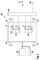
- Fig. 2 shows a measuring device 200, which on the measuring element 100 from Fig. 1 based.
- the measuring device 200 comprises the measuring element 100, a further measuring element 210 and optionally a device 220 for signal processing, which comprises an operational amplifier 225 and a feedback resistor 230.
- the measuring element 210 is basically constructed identically to the measuring element 100 and in particular has identical dimensions, but in contrast to the measuring element 100 does not comprise any moving parts.
- a gate electrode of the measuring element 210 is fixed in a position that is at the measuring device 100 corresponds to an undeflected position of its gate electrode G.
- the gate electrodes are connected to the respective drain terminals D, so that both measuring elements 100 and 210 are operated current-controlling.
- the measuring elements 100 and 210 are connected in series and connected to two terminals VCC and GND of a DC voltage source (not shown).
- the measuring elements 100 and 210 are bipolar, therefore, a polarity of the DC voltage is irrelevant.
- an output signal can be tapped, which stands for the deflection of the gate electrode G in the measuring element 100 in a non-linear relationship.
- the combination of the measuring elements 100 and 210 in the manner shown compensates for constant errors, which are due, for example, to manufacturing inaccuracies of the measuring elements 100 and 210.
- the signal processing device 220 generates a voltage signal which varies with the deflection of the gate electrode G of the measuring element 100 in a manner known to the person skilled in the art by means of an operational amplifier 225 fed back by means of the feedback resistor 230.
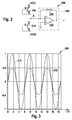
- FIG. 15 shows a diagram 300 which shows a relationship between a harmonic deflection 310 (broken line) of the gate electrode G of the measuring element 100 from the FIGS. 1a, 1b and an output signal 320 (solid line) of the signal processing means 220 Fig. 2 represents.
- a harmonic deflection 310 broken line
- an output signal 320 solid line
- the horizontal direction is a time course, in the vertical direction, a percentage deflection (with respect to 310) or a voltage (with respect to 320) plotted.
- the profile 310 of a sinusoidal, harmonic excursion of G causes an output voltage 320 corresponding to a symmetrical sawtooth or a trapezoid.
- This relationship stems from the particular shape of area 120 as a clipped circle or clipped ellipse, as in FIG Fig. 1b shown and described in more detail above.
- the sinusoidal, harmonic deflection 310 can be transmitted to the gate electrode G by a micromechanically structured actuator.
- a micromechanically structured actuator For example, by means of the measuring element 100 Fig. 1 with the help of a capacitive, piezoelectric, thermoelastic or magnetic drive a micro-electromechanical resonator can be constructed. According to its use, the resonator may be more or less damped, for example by gas confinement in a space in which the gate electrode G is deflectably arranged.
- the actuator and the in Fig. 2 Elements shown can form a micro-electro-mechanical signal generator that can be used in many ways. With such a signal generator, by varying the shapes of the gate electrode G and / or the region 120, a series of differently shaped periodic signals can be generated.
- the sensing element 100 can be used widely within micro-electro-mechanical and opto-micro-electro-mechanical devices.
- it may form a measuring device 200 together with further measuring elements 100, 210 and / or a device 220 for signal processing.
- a non-linearity of the signal processing device (and / or another signal processing device) can thus be compensated by the nonlinearity of the relationship between the deflection of the gate electrode G of the measuring element 100 and the current flow through the measuring element 100, so that overall There is an association between the deflection of the gate electrode G with respect to the region 120 and the output signal of the signal processing device.
- the measuring element 100 or the measuring device 200 may form a system or an assembly together with other mechanical, optical and / or electronic components.
- the measuring element 100 may be part of an initial sensor, a rotation rate sensor or a micromirror. In the latter case, there would be an opto-mechanical micro-electro-mechanical system (Micro-Opto-Mechanical System, MOEMS).
- MOEMS opto-mechanical micro-electro-mechanical system
- FIG. 4 shows a resonator 400 in a FIGS. 1 a and 1 b corresponding representation.
- the resonator 400 comprises a substrate 110 with a plurality of source terminals S and drain terminals D, which delimit pairwise channels 120, a common electrode G, a processing device 220, springs 410, a drive 420, a damper 430 and an output 440th
- the processing device 220 is connected to the source terminals S and the drain terminals D and determines an output signal according to the above explanations, which provides them at the output 440.
- the electrode G is arranged in the z-direction over the channels 120 by means of the springs 410 and can be deflected by the drive 420 in the y-direction.
- the electrode G has recesses, so that the channels 120 more or less overlap with these depending on a deflection of the electrode G. Due to the overlapping of the electrode G with a plurality of channels 120, an increased sensitivity of the deflection measurement can be achieved in the illustrated resonator 400.
- At least one of the springs 410 serves at the same time as an electrical contact to an anchor element, not shown, for the resonator 400, which may carry, for example, the substrate 110 or may coincide therewith.
- the deflection of the electrode G is damped by means of the damper 430.
- This may be e.g. to act a friction or eddy current damper or the electrode G may be enclosed in a container with a gas of a predetermined pressure.
- the latter variant is particularly suitable for low attenuation in order to operate the resonator 400 at a high quality.
- the damping can also be effected by fluidic effects on the remaining movable structure and by "anchor loss".
- the damper 430 is omitted.
- the electrode G may be part of or associated with a micromirror.
- a micromirror system for example, an actual deflection of the electrode G can be determined on the basis of the signal provided at the output 440 and the drive 420 can be controlled accordingly in order to achieve a predetermined deflection of the electrode G.
- the electrode G may be part of an inertial system. The deflection of the electrode G can then be determined absolutely or as a function of a deflection of the electrode G induced by the drive 420, which allows conclusions to be drawn on a movement of the inertial system.
Landscapes
- Engineering & Computer Science (AREA)
- Power Engineering (AREA)
- Physics & Mathematics (AREA)
- General Physics & Mathematics (AREA)
- Micromachines (AREA)
- Junction Field-Effect Transistors (AREA)
- Particle Formation And Scattering Control In Inkjet Printers (AREA)
- Peptides Or Proteins (AREA)
Claims (13)
- Elément de mesure (100) conçu pour enregistrer une déviation, comprenant :- une région (120) disposée sur un substrat à semiconducteur (110), qui s'étend entre une borne de source (S) et une borne de drain (D), et une électrode (G) conçue pour agir sur la conductivité de la région (120) ;- dans lequel l'électrode (G) est placée de manière à pouvoir être déviée par rapport à la région (120) afin de créer entre l'électrode (G) et la région (120) une région de chevauchement (130) qui présente un évidement variant avec une déviation de l'électrode (G),- dans lequel le signal de sortie de l'élément de mesure (100) dépend de la conductivité de la région (120) et peut être commandé par la modification de l'évidement de la région de chevauchement (130),- la région et/ou l'électrode sont conçues de manière à ce que la modification de l'évidement de la région de chevauchement (130) présente avec la déviation de l'électrode (G) une relation non linéaire de manière à ce qu'une modification du signal de sortie de l'élément de mesure (100) présente une relation non linéaire avec la déviation de l'électrode (G),dans lequel- l'électrode (G) est placée au-dessus de la région (120), dans lequel la distance entre l'électrode (G) et la région (120) reste constante, et- une surface de la région (120) est déterminée par une largeur W s'étendant dans une direction de déviation y de l'électrode (G) et par une longueur L de l'électrode (G) s'étendant perpendiculairement à celle-ci, et la relation suivante est vérifiée :

- Elément de mesure (100) selon la revendication 1, caractérisé en ce que l'électrode (G) et la région (120) sont disposées de manière espacée l'une de l'autre.
- Elément de mesure (100) selon la revendication 1, dans lequel la longueur (L) de la région (120) n'est pas constante sur la largeur (W) de la région (120).
- Elément de mesure (100) selon l'une quelconque des revendications précédentes, dans lequel la borne de drain (D) et/ou la borne de source (S) présentent une ligne de bord de la région (120) sous la forme d'un segment d'ellipse.
- Elément de mesure (100) selon la revendication 1, caractérisé en ce que la région (120) présente une longueur L variable entre la borne de drain (D) et la borne de source (S), dans lequel, pour la longueur L la relation suivante est vérifiée, en fonction de la direction de déviation y de l'électrode (G):

- Elément de mesure (100) selon l'une quelconque des revendications 1 à 5, dans lequel la région (120) est le canal d'un transistor à effet de champ et est au moins partiellement recouverte par l'électrode (G) lors de la déviation de cette dernière.
- Elément de mesure (100) selon l'une quelconque des revendications 1 à 6, dans lequel l'électrode (G) est perforée.
- Elément de mesure (100) selon l'une quelconque des revendications 1 à 7, dans lequel l'électrode (G) fait partie d'un micro-miroir ou d'un capteur à inertie.
- Elément de mesure (100) selon l'une quelconque des revendications 1 à 8, comprenant en outre un élément élastique (410) au moyen duquel l'électrode (G) peut être placée de manière à pouvoir être déviée sur le substrat à semi-conducteur (110).
- Elément de mesure (100) selon l'une quelconque des revendications 1 à 9, dans lequel une pluralité de canaux (120) sont associés à une électrode (G).
- Résonateur (400), comprenant :un élément de mesure (100) qui est conçu pour recevoir une déviation selon l'une quelconque des revendications 1 à 10, et un dispositif d'entraînement (420), dans lequel l'élément de mesure comprend :et la relation suivante est vérifiée :- une région (120) disposée sur un substrat à semi-conducteur (110), qui s'étend entre une borne de source (S) et une borne de drain (D), et une électrode (G) conçue pour agir sur la conductivité de la région (120) ;- dans lequel l'électrode (G) est placée de manière à pouvoir être déviée par rapport à la région (120) de afin de créer entre l'électrode (G) et la région (120) une région de chevauchement (130) qui présente un évidement variant avec une déviation de l'électrode (G),- dans lequel le signal de sortie de l'élément de mesure (100) dépend de la conductivité de la région (120) et peut être commandé par la modification de l'évidement de la région de chevauchement (130),- la région et/ou l'électrode sont conçues de manière à ce que la modification de l'évidement de la région de chevauchement (130) présente avec la déviation de l'électrode (G) une relation non linéaire de manière à ce qu'une modification du signal de sortie de l'élément de mesure (100) présente une relation non linéaire avec la déviation de l'électrode (G),dans lequel- l'électrode (G) est placée au-dessus de la région (120), dans lequel la distance entre l'électrode (G) et la région (120) reste constante, et- une surface de la région (120) est déterminée par une largeur W s'étendant dans une direction de déviation y de l'électrode (G) et par une longueur L de l'électrode (G) s'étendant perpendiculairement à celle-ci,
 dans lequel le dispositif d'entraînement (420) dévie l'électrode (G) de manière périodique.
 - Résonateur (400) selon la revendication 11, caractérisé en ce qu'il est prévu au moins deux éléments de mesure (100), dans lequel les éléments de mesure (100) comprennent un substrat à semi-conducteur commun (110) comportant une pluralité de bornes de source (S) et de bornes de drain (D) qui délimitent par paires des régions (120), et une électrode commune (G), dans lequel il est prévu une unité de traitement (220) qui est connectée aux bornes de source (S) et aux bornes de drain (D) et qui fournit un signal de sortie en fonction de la déviation de l'électrode (G) sous la forme d'une relation non linéaire.
- Résonateur selon la revendication 12, caractérisé en ce que le dispositif d'entraînement (420) transmet une déviation sinusoïdale harmonique (310) à l'électrode (G), dans lequel l'unité de traitement (220) produit une tension de sortie (320), en fonction de ladite déviation sinusoïdale (310), qui correspond à une dent de scie ou à un trapèze symétrique.
Applications Claiming Priority (2)
| Application Number | Priority Date | Filing Date | Title |
|---|---|---|---|
| DE102009002723A DE102009002723A1 (de) | 2009-04-29 | 2009-04-29 | Messelement |
| PCT/EP2010/052527 WO2010124889A2 (fr) | 2009-04-29 | 2010-03-01 | Élément de mesure |
Publications (2)
| Publication Number | Publication Date |
|---|---|
| EP2425208A2 EP2425208A2 (fr) | 2012-03-07 |
| EP2425208B1 true EP2425208B1 (fr) | 2016-05-11 |
Family
ID=42813536
Family Applications (1)
| Application Number | Title | Priority Date | Filing Date |
|---|---|---|---|
| EP10708754.6A Not-in-force EP2425208B1 (fr) | 2009-04-29 | 2010-03-01 | Élément de mesure |
Country Status (4)
| Country | Link |
|---|---|
| US (1) | US9086302B2 (fr) |
| EP (1) | EP2425208B1 (fr) |
| DE (1) | DE102009002723A1 (fr) |
| WO (1) | WO2010124889A2 (fr) |
Families Citing this family (4)
| Publication number | Priority date | Publication date | Assignee | Title |
|---|---|---|---|---|
| DE102009045422B4 (de) | 2009-10-07 | 2024-05-02 | Robert Bosch Gmbh | Sensoranordnung und Verfahren zum Betrieb einer Sensoranordnung |
| DE102011075541A1 (de) | 2011-05-10 | 2012-11-15 | Robert Bosch Gmbh | Auswerteschaltung für Feldeffekttransistor mit beweglicher Gatestruktur |
| DE102012202783A1 (de) * | 2012-02-23 | 2013-08-29 | Robert Bosch Gmbh | Mikromechanische Sensorvorrichtung mit beweglichem Gate und entsprechendes Herstellungsverfahren |
| US12253391B2 (en) | 2018-05-24 | 2025-03-18 | The Research Foundation For The State University Of New York | Multielectrode capacitive sensor without pull-in risk |
Citations (2)
| Publication number | Priority date | Publication date | Assignee | Title |
|---|---|---|---|---|
| EP0693672A1 (fr) * | 1994-07-01 | 1996-01-24 | Dr. Johannes Heidenhain GmbH | Dispositif de mesure de longueurs ou d'angles |
| WO2005080921A1 (fr) * | 2004-02-19 | 2005-09-01 | Eaton Automotive B.V. | Systeme de commande mecatronique |
Family Cites Families (5)
| Publication number | Priority date | Publication date | Assignee | Title |
|---|---|---|---|---|
| US4157462A (en) * | 1977-10-26 | 1979-06-05 | General Motors Corporation | Sensor |
| US5457368A (en) * | 1993-03-09 | 1995-10-10 | University Of Utah Research Foundation | Mechanical/electrical displacement transducer |
| US5198740A (en) * | 1989-10-04 | 1993-03-30 | University Of Utah Research Foundation | Sliding contact mechanical/electrical displacement transducer |
| EP0700065B1 (fr) * | 1994-08-31 | 2001-09-19 | AT&T Corp. | Dispositif à émission de champ et procédé de fabrication |
| US6220096B1 (en) | 1997-03-20 | 2001-04-24 | Interscience, Inc. | Differential wideband vibration |
-
2009
- 2009-04-29 DE DE102009002723A patent/DE102009002723A1/de not_active Withdrawn
-
2010
- 2010-03-01 EP EP10708754.6A patent/EP2425208B1/fr not_active Not-in-force
- 2010-03-01 WO PCT/EP2010/052527 patent/WO2010124889A2/fr not_active Ceased
- 2010-03-01 US US13/258,570 patent/US9086302B2/en active Active
Patent Citations (2)
| Publication number | Priority date | Publication date | Assignee | Title |
|---|---|---|---|---|
| EP0693672A1 (fr) * | 1994-07-01 | 1996-01-24 | Dr. Johannes Heidenhain GmbH | Dispositif de mesure de longueurs ou d'angles |
| WO2005080921A1 (fr) * | 2004-02-19 | 2005-09-01 | Eaton Automotive B.V. | Systeme de commande mecatronique |
Also Published As
| Publication number | Publication date |
|---|---|
| WO2010124889A4 (fr) | 2011-04-14 |
| US9086302B2 (en) | 2015-07-21 |
| EP2425208A2 (fr) | 2012-03-07 |
| WO2010124889A2 (fr) | 2010-11-04 |
| WO2010124889A3 (fr) | 2011-01-13 |
| US20120025277A1 (en) | 2012-02-02 |
| DE102009002723A1 (de) | 2010-11-04 |
Similar Documents
| Publication | Publication Date | Title |
|---|---|---|
| EP2389561B1 (fr) | Capteur de vitesse de rotation | |
| EP1373831B1 (fr) | Detecteur de vitesse de rotation | |
| EP1377797B1 (fr) | Detecteur de vitesse de rotation | |
| DE102012200929B4 (de) | Mikromechanische Struktur und Verfahren zur Herstellung einer mikromechanischen Struktur | |
| WO2008074538A1 (fr) | Détecteur d'accélération avec électrodes à dents | |
| DE4432837A1 (de) | Beschleunigungssensor und Meßverfahren | |
| DE102009000606A1 (de) | Mikromechanische Strukturen | |
| DE102008040855A1 (de) | Dreiachsiger Beschleunigungssensor | |
| DE112013002514T5 (de) | Sensorvorrichtung | |
| EP2425208B1 (fr) | Élément de mesure | |
| DE102013212059B4 (de) | Mikromechanischer Inertialsensor | |
| DE102009045420B4 (de) | Drehratensensor, Drehratensensoranordnung und Verfahren zum Betrieb eines Drehratensensors | |
| DE102008054749A1 (de) | Drehratensensor und Verfahren zum Betrieb eines Drehratensensors | |
| DE102009028343A1 (de) | Sensorelement und Verfahren zum Betrieb eines Sensorelements | |
| DE102013216935A1 (de) | Drehratensensor mit voreingestelltem Quadratur-Offset | |
| DE102008040567B4 (de) | Verfahren zum Betrieb eines Sensormoduls und Sensormodul | |
| DE112006003699B4 (de) | Auslenkbares mikromechanisches System sowie dessen Verwendung | |
| DE19744292A1 (de) | Elektrostatischer Aktor und Sensor | |
| EP1608988B1 (fr) | Capteur d'acceleration et procede de detection d'une acceleration | |
| DE102020210121A1 (de) | Mikromechanisches System, Verfahren zum Betreiben eines mikromechanischen Systems | |
| DE102010038919B4 (de) | Mikromechanisches System | |
| DE4431232A1 (de) | Integrierbares Feder-Masse-System | |
| DE102011080982B4 (de) | Sensoranordnung | |
| DE102010039236B4 (de) | Sensoranordnung und Verfahren zum Abgleich einer Sensoranordnung | |
| DE19813941A1 (de) | Mikromechanischer Beschleunigungssensor |
Legal Events
| Date | Code | Title | Description |
|---|---|---|---|
| PUAI | Public reference made under article 153(3) epc to a published international application that has entered the european phase |
Free format text: ORIGINAL CODE: 0009012 |
|
| 17P | Request for examination filed |
Effective date: 20111129 |
|
| AK | Designated contracting states |
Kind code of ref document: A2 Designated state(s): AT BE BG CH CY CZ DE DK EE ES FI FR GB GR HR HU IE IS IT LI LT LU LV MC MK MT NL NO PL PT RO SE SI SK SM TR |
|
| DAX | Request for extension of the european patent (deleted) | ||
| 17Q | First examination report despatched |
Effective date: 20150511 |
|
| GRAP | Despatch of communication of intention to grant a patent |
Free format text: ORIGINAL CODE: EPIDOSNIGR1 |
|
| INTG | Intention to grant announced |
Effective date: 20151216 |
|
| GRAS | Grant fee paid |
Free format text: ORIGINAL CODE: EPIDOSNIGR3 |
|
| GRAA | (expected) grant |
Free format text: ORIGINAL CODE: 0009210 |
|
| AK | Designated contracting states |
Kind code of ref document: B1 Designated state(s): AT BE BG CH CY CZ DE DK EE ES FI FR GB GR HR HU IE IS IT LI LT LU LV MC MK MT NL NO PL PT RO SE SI SK SM TR |
|
| REG | Reference to a national code |
Ref country code: GB Ref legal event code: FG4D Free format text: NOT ENGLISH |
|
| REG | Reference to a national code |
Ref country code: CH Ref legal event code: EP |
|
| REG | Reference to a national code |
Ref country code: AT Ref legal event code: REF Ref document number: 799010 Country of ref document: AT Kind code of ref document: T Effective date: 20160515 |
|
| REG | Reference to a national code |
Ref country code: IE Ref legal event code: FG4D Free format text: LANGUAGE OF EP DOCUMENT: GERMAN |
|
| REG | Reference to a national code |
Ref country code: DE Ref legal event code: R096 Ref document number: 502010011649 Country of ref document: DE |
|
| REG | Reference to a national code |
Ref country code: LT Ref legal event code: MG4D |
|
| REG | Reference to a national code |
Ref country code: NL Ref legal event code: MP Effective date: 20160511 |
|
| PG25 | Lapsed in a contracting state [announced via postgrant information from national office to epo] |
Ref country code: NO Free format text: LAPSE BECAUSE OF FAILURE TO SUBMIT A TRANSLATION OF THE DESCRIPTION OR TO PAY THE FEE WITHIN THE PRESCRIBED TIME-LIMIT Effective date: 20160811 Ref country code: LT Free format text: LAPSE BECAUSE OF FAILURE TO SUBMIT A TRANSLATION OF THE DESCRIPTION OR TO PAY THE FEE WITHIN THE PRESCRIBED TIME-LIMIT Effective date: 20160511 Ref country code: FI Free format text: LAPSE BECAUSE OF FAILURE TO SUBMIT A TRANSLATION OF THE DESCRIPTION OR TO PAY THE FEE WITHIN THE PRESCRIBED TIME-LIMIT Effective date: 20160511 Ref country code: NL Free format text: LAPSE BECAUSE OF FAILURE TO SUBMIT A TRANSLATION OF THE DESCRIPTION OR TO PAY THE FEE WITHIN THE PRESCRIBED TIME-LIMIT Effective date: 20160511 |
|
| PG25 | Lapsed in a contracting state [announced via postgrant information from national office to epo] |
Ref country code: HR Free format text: LAPSE BECAUSE OF FAILURE TO SUBMIT A TRANSLATION OF THE DESCRIPTION OR TO PAY THE FEE WITHIN THE PRESCRIBED TIME-LIMIT Effective date: 20160511 Ref country code: GR Free format text: LAPSE BECAUSE OF FAILURE TO SUBMIT A TRANSLATION OF THE DESCRIPTION OR TO PAY THE FEE WITHIN THE PRESCRIBED TIME-LIMIT Effective date: 20160812 Ref country code: LV Free format text: LAPSE BECAUSE OF FAILURE TO SUBMIT A TRANSLATION OF THE DESCRIPTION OR TO PAY THE FEE WITHIN THE PRESCRIBED TIME-LIMIT Effective date: 20160511 Ref country code: SE Free format text: LAPSE BECAUSE OF FAILURE TO SUBMIT A TRANSLATION OF THE DESCRIPTION OR TO PAY THE FEE WITHIN THE PRESCRIBED TIME-LIMIT Effective date: 20160511 Ref country code: PT Free format text: LAPSE BECAUSE OF FAILURE TO SUBMIT A TRANSLATION OF THE DESCRIPTION OR TO PAY THE FEE WITHIN THE PRESCRIBED TIME-LIMIT Effective date: 20160912 Ref country code: ES Free format text: LAPSE BECAUSE OF FAILURE TO SUBMIT A TRANSLATION OF THE DESCRIPTION OR TO PAY THE FEE WITHIN THE PRESCRIBED TIME-LIMIT Effective date: 20160511 |
|
| PG25 | Lapsed in a contracting state [announced via postgrant information from national office to epo] |
Ref country code: RO Free format text: LAPSE BECAUSE OF FAILURE TO SUBMIT A TRANSLATION OF THE DESCRIPTION OR TO PAY THE FEE WITHIN THE PRESCRIBED TIME-LIMIT Effective date: 20160511 Ref country code: EE Free format text: LAPSE BECAUSE OF FAILURE TO SUBMIT A TRANSLATION OF THE DESCRIPTION OR TO PAY THE FEE WITHIN THE PRESCRIBED TIME-LIMIT Effective date: 20160511 Ref country code: SK Free format text: LAPSE BECAUSE OF FAILURE TO SUBMIT A TRANSLATION OF THE DESCRIPTION OR TO PAY THE FEE WITHIN THE PRESCRIBED TIME-LIMIT Effective date: 20160511 Ref country code: DK Free format text: LAPSE BECAUSE OF FAILURE TO SUBMIT A TRANSLATION OF THE DESCRIPTION OR TO PAY THE FEE WITHIN THE PRESCRIBED TIME-LIMIT Effective date: 20160511 Ref country code: CZ Free format text: LAPSE BECAUSE OF FAILURE TO SUBMIT A TRANSLATION OF THE DESCRIPTION OR TO PAY THE FEE WITHIN THE PRESCRIBED TIME-LIMIT Effective date: 20160511 |
|
| REG | Reference to a national code |
Ref country code: DE Ref legal event code: R097 Ref document number: 502010011649 Country of ref document: DE |
|
| PG25 | Lapsed in a contracting state [announced via postgrant information from national office to epo] |
Ref country code: SM Free format text: LAPSE BECAUSE OF FAILURE TO SUBMIT A TRANSLATION OF THE DESCRIPTION OR TO PAY THE FEE WITHIN THE PRESCRIBED TIME-LIMIT Effective date: 20160511 Ref country code: PL Free format text: LAPSE BECAUSE OF FAILURE TO SUBMIT A TRANSLATION OF THE DESCRIPTION OR TO PAY THE FEE WITHIN THE PRESCRIBED TIME-LIMIT Effective date: 20160511 |
|
| PLBE | No opposition filed within time limit |
Free format text: ORIGINAL CODE: 0009261 |
|
| STAA | Information on the status of an ep patent application or granted ep patent |
Free format text: STATUS: NO OPPOSITION FILED WITHIN TIME LIMIT |
|
| REG | Reference to a national code |
Ref country code: FR Ref legal event code: PLFP Year of fee payment: 8 |
|
| 26N | No opposition filed |
Effective date: 20170214 |
|
| PG25 | Lapsed in a contracting state [announced via postgrant information from national office to epo] |
Ref country code: SI Free format text: LAPSE BECAUSE OF FAILURE TO SUBMIT A TRANSLATION OF THE DESCRIPTION OR TO PAY THE FEE WITHIN THE PRESCRIBED TIME-LIMIT Effective date: 20160511 |
|
| REG | Reference to a national code |
Ref country code: CH Ref legal event code: PL |
|
| GBPC | Gb: european patent ceased through non-payment of renewal fee |
Effective date: 20170301 |
|
| PG25 | Lapsed in a contracting state [announced via postgrant information from national office to epo] |
Ref country code: MC Free format text: LAPSE BECAUSE OF FAILURE TO SUBMIT A TRANSLATION OF THE DESCRIPTION OR TO PAY THE FEE WITHIN THE PRESCRIBED TIME-LIMIT Effective date: 20160511 |
|
| REG | Reference to a national code |
Ref country code: IE Ref legal event code: MM4A |
|
| PG25 | Lapsed in a contracting state [announced via postgrant information from national office to epo] |
Ref country code: LU Free format text: LAPSE BECAUSE OF NON-PAYMENT OF DUE FEES Effective date: 20170301 |
|
| PG25 | Lapsed in a contracting state [announced via postgrant information from national office to epo] |
Ref country code: LI Free format text: LAPSE BECAUSE OF NON-PAYMENT OF DUE FEES Effective date: 20170331 Ref country code: GB Free format text: LAPSE BECAUSE OF NON-PAYMENT OF DUE FEES Effective date: 20170301 Ref country code: IE Free format text: LAPSE BECAUSE OF NON-PAYMENT OF DUE FEES Effective date: 20170301 Ref country code: CH Free format text: LAPSE BECAUSE OF NON-PAYMENT OF DUE FEES Effective date: 20170331 |
|
| REG | Reference to a national code |
Ref country code: BE Ref legal event code: MM Effective date: 20170331 |
|
| REG | Reference to a national code |
Ref country code: FR Ref legal event code: PLFP Year of fee payment: 9 |
|
| REG | Reference to a national code |
Ref country code: AT Ref legal event code: MM01 Ref document number: 799010 Country of ref document: AT Kind code of ref document: T Effective date: 20170301 |
|
| PG25 | Lapsed in a contracting state [announced via postgrant information from national office to epo] |
Ref country code: BE Free format text: LAPSE BECAUSE OF NON-PAYMENT OF DUE FEES Effective date: 20170331 |
|
| PG25 | Lapsed in a contracting state [announced via postgrant information from national office to epo] |
Ref country code: AT Free format text: LAPSE BECAUSE OF NON-PAYMENT OF DUE FEES Effective date: 20170301 |
|
| PG25 | Lapsed in a contracting state [announced via postgrant information from national office to epo] |
Ref country code: MT Free format text: LAPSE BECAUSE OF FAILURE TO SUBMIT A TRANSLATION OF THE DESCRIPTION OR TO PAY THE FEE WITHIN THE PRESCRIBED TIME-LIMIT Effective date: 20160511 |
|
| PG25 | Lapsed in a contracting state [announced via postgrant information from national office to epo] |
Ref country code: HU Free format text: LAPSE BECAUSE OF FAILURE TO SUBMIT A TRANSLATION OF THE DESCRIPTION OR TO PAY THE FEE WITHIN THE PRESCRIBED TIME-LIMIT; INVALID AB INITIO Effective date: 20100301 |
|
| PG25 | Lapsed in a contracting state [announced via postgrant information from national office to epo] |
Ref country code: BG Free format text: LAPSE BECAUSE OF FAILURE TO SUBMIT A TRANSLATION OF THE DESCRIPTION OR TO PAY THE FEE WITHIN THE PRESCRIBED TIME-LIMIT Effective date: 20160511 |
|
| PG25 | Lapsed in a contracting state [announced via postgrant information from national office to epo] |
Ref country code: CY Free format text: LAPSE BECAUSE OF NON-PAYMENT OF DUE FEES Effective date: 20160511 |
|
| PG25 | Lapsed in a contracting state [announced via postgrant information from national office to epo] |
Ref country code: MK Free format text: LAPSE BECAUSE OF FAILURE TO SUBMIT A TRANSLATION OF THE DESCRIPTION OR TO PAY THE FEE WITHIN THE PRESCRIBED TIME-LIMIT Effective date: 20160511 |
|
| PG25 | Lapsed in a contracting state [announced via postgrant information from national office to epo] |
Ref country code: TR Free format text: LAPSE BECAUSE OF FAILURE TO SUBMIT A TRANSLATION OF THE DESCRIPTION OR TO PAY THE FEE WITHIN THE PRESCRIBED TIME-LIMIT Effective date: 20160511 |
|
| PG25 | Lapsed in a contracting state [announced via postgrant information from national office to epo] |
Ref country code: IS Free format text: LAPSE BECAUSE OF FAILURE TO SUBMIT A TRANSLATION OF THE DESCRIPTION OR TO PAY THE FEE WITHIN THE PRESCRIBED TIME-LIMIT Effective date: 20160911 |
|
| PGFP | Annual fee paid to national office [announced via postgrant information from national office to epo] |
Ref country code: FR Payment date: 20220322 Year of fee payment: 13 |
|
| PGFP | Annual fee paid to national office [announced via postgrant information from national office to epo] |
Ref country code: IT Payment date: 20220331 Year of fee payment: 13 |
|
| PGFP | Annual fee paid to national office [announced via postgrant information from national office to epo] |
Ref country code: DE Payment date: 20230524 Year of fee payment: 14 |
|
| PG25 | Lapsed in a contracting state [announced via postgrant information from national office to epo] |
Ref country code: FR Free format text: LAPSE BECAUSE OF NON-PAYMENT OF DUE FEES Effective date: 20230331 |
|
| PG25 | Lapsed in a contracting state [announced via postgrant information from national office to epo] |
Ref country code: IT Free format text: LAPSE BECAUSE OF NON-PAYMENT OF DUE FEES Effective date: 20230301 |
|
| REG | Reference to a national code |
Ref country code: DE Ref legal event code: R119 Ref document number: 502010011649 Country of ref document: DE |
|
| PG25 | Lapsed in a contracting state [announced via postgrant information from national office to epo] |
Ref country code: DE Free format text: LAPSE BECAUSE OF NON-PAYMENT OF DUE FEES Effective date: 20241001 |
|
| PG25 | Lapsed in a contracting state [announced via postgrant information from national office to epo] |
Ref country code: DE Free format text: LAPSE BECAUSE OF NON-PAYMENT OF DUE FEES Effective date: 20241001 |