EP2425157B1 - Siège de ressort à auto-centrage pour régulateur de fluide et régulateur de fluide comprenant un siège de ressort à auto-centrage - Google Patents
Siège de ressort à auto-centrage pour régulateur de fluide et régulateur de fluide comprenant un siège de ressort à auto-centrage Download PDFInfo
- Publication number
- EP2425157B1 EP2425157B1 EP20100719471 EP10719471A EP2425157B1 EP 2425157 B1 EP2425157 B1 EP 2425157B1 EP 20100719471 EP20100719471 EP 20100719471 EP 10719471 A EP10719471 A EP 10719471A EP 2425157 B1 EP2425157 B1 EP 2425157B1
- Authority
- EP
- European Patent Office
- Prior art keywords
- spring seat
- spring
- control member
- seat
- tubular control
- Prior art date
- Legal status (The legal status is an assumption and is not a legal conclusion. Google has not performed a legal analysis and makes no representation as to the accuracy of the status listed.)
- Active
Links
Images


Classifications
-
- F—MECHANICAL ENGINEERING; LIGHTING; HEATING; WEAPONS; BLASTING
- F16—ENGINEERING ELEMENTS AND UNITS; GENERAL MEASURES FOR PRODUCING AND MAINTAINING EFFECTIVE FUNCTIONING OF MACHINES OR INSTALLATIONS; THERMAL INSULATION IN GENERAL
- F16K—VALVES; TAPS; COCKS; ACTUATING-FLOATS; DEVICES FOR VENTING OR AERATING
- F16K3/00—Gate valves or sliding valves, i.e. cut-off apparatus with closing members having a sliding movement along the seat for opening and closing
- F16K3/22—Gate valves or sliding valves, i.e. cut-off apparatus with closing members having a sliding movement along the seat for opening and closing with sealing faces shaped as surfaces of solids of revolution
- F16K3/24—Gate valves or sliding valves, i.e. cut-off apparatus with closing members having a sliding movement along the seat for opening and closing with sealing faces shaped as surfaces of solids of revolution with cylindrical valve members
- F16K3/246—Combination of a sliding valve and a lift valve
-
- F—MECHANICAL ENGINEERING; LIGHTING; HEATING; WEAPONS; BLASTING
- F16—ENGINEERING ELEMENTS AND UNITS; GENERAL MEASURES FOR PRODUCING AND MAINTAINING EFFECTIVE FUNCTIONING OF MACHINES OR INSTALLATIONS; THERMAL INSULATION IN GENERAL
- F16K—VALVES; TAPS; COCKS; ACTUATING-FLOATS; DEVICES FOR VENTING OR AERATING
- F16K1/00—Lift valves or globe valves, i.e. cut-off apparatus with closure members having at least a component of their opening and closing motion perpendicular to the closing faces
- F16K1/32—Details
- F16K1/34—Cutting-off parts, e.g. valve members, seats
- F16K1/42—Valve seats
- F16K1/422—Valve seats attachable by a threaded connection to the housing
-
- F—MECHANICAL ENGINEERING; LIGHTING; HEATING; WEAPONS; BLASTING
- F16—ENGINEERING ELEMENTS AND UNITS; GENERAL MEASURES FOR PRODUCING AND MAINTAINING EFFECTIVE FUNCTIONING OF MACHINES OR INSTALLATIONS; THERMAL INSULATION IN GENERAL
- F16K—VALVES; TAPS; COCKS; ACTUATING-FLOATS; DEVICES FOR VENTING OR AERATING
- F16K31/00—Actuating devices; Operating means; Releasing devices
- F16K31/12—Actuating devices; Operating means; Releasing devices actuated by fluid
- F16K31/126—Actuating devices; Operating means; Releasing devices actuated by fluid the fluid acting on a diaphragm, bellows, or the like
- F16K31/1262—Actuating devices; Operating means; Releasing devices actuated by fluid the fluid acting on a diaphragm, bellows, or the like one side of the diaphragm being spring loaded
-
- Y—GENERAL TAGGING OF NEW TECHNOLOGICAL DEVELOPMENTS; GENERAL TAGGING OF CROSS-SECTIONAL TECHNOLOGIES SPANNING OVER SEVERAL SECTIONS OF THE IPC; TECHNICAL SUBJECTS COVERED BY FORMER USPC CROSS-REFERENCE ART COLLECTIONS [XRACs] AND DIGESTS
- Y10—TECHNICAL SUBJECTS COVERED BY FORMER USPC
- Y10T—TECHNICAL SUBJECTS COVERED BY FORMER US CLASSIFICATION
- Y10T137/00—Fluid handling
- Y10T137/7722—Line condition change responsive valves
- Y10T137/7781—With separate connected fluid reactor surface
- Y10T137/7793—With opening bias [e.g., pressure regulator]
- Y10T137/7809—Reactor surface separated by apertured partition
- Y10T137/782—Reactor surface is diaphragm
- Y10T137/7821—With valve closing bias
-
- Y—GENERAL TAGGING OF NEW TECHNOLOGICAL DEVELOPMENTS; GENERAL TAGGING OF CROSS-SECTIONAL TECHNOLOGIES SPANNING OVER SEVERAL SECTIONS OF THE IPC; TECHNICAL SUBJECTS COVERED BY FORMER USPC CROSS-REFERENCE ART COLLECTIONS [XRACs] AND DIGESTS
- Y10—TECHNICAL SUBJECTS COVERED BY FORMER USPC
- Y10T—TECHNICAL SUBJECTS COVERED BY FORMER US CLASSIFICATION
- Y10T137/00—Fluid handling
- Y10T137/7722—Line condition change responsive valves
- Y10T137/7781—With separate connected fluid reactor surface
- Y10T137/7834—Valve seat or external sleeve moves to open valve
Definitions
- the present disclosure generally relates to a fluid control device and, more particularly, to a fluid control device including a positioning device and a positioning device for a fluid control device.
- Fluid control devices include various categories of equipment including control valves and regulators. Such control devices are adapted to be coupled within a fluid process control system such as chemical treatment systems, natural gas delivery systems, etc., for controlling the flow of a fluid therethrough. Each control device defines a fluid flow-path and includes a control member for adjusting a dimension of the flow-path.
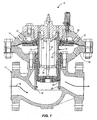
- FIG. 1 depicts a known regulator 10 including a valve body 12 and an actuator 14.
- the valve body 12 defines a flow-path 16 and includes a throat 18.
- the regulator 10 is configured in a flow-up configuration.
- the actuator 14 includes an upper actuator casing 20, a lower actuator casing 22, a diaphragm subassembly 30 including a diaphragm 32, and a positioning device assembly 34.
- the positioning device assembly 34 includes a tubular control member 33, a coil spring 35, a central rod 36, a first spring seat 38, and a second spring seat 40.
- the tubular control member 33 is disposed within the upper and lower actuator casings 20, 22 and is adapted for bidirectional displacement in response to changes in pressure across the diaphragm subassembly 30. So configured, the tubular control member 33 controls the flow of fluid through the throat 18 of the valve body 12.
- the regulator 10 includes a seat ring 26 disposed in the throat 18 of the valve body 12. When the outlet pressure of the valve body 12 is high, a sealing surface 28 of the positioning device assembly 34 may sealingly engage the seat ring 26 and close the throat 18.
- the coil spring 35 which is carried by the central rod 36, and disposed within the tubular control member 33 biases the tubular control member 33 into an open position, which is illustrated in Fig. 1 .
- the coil spring 35 of the conventional regulator 10 is carried by the central rod 36 between the first spring seat 38 and the second spring seat 40.
- the first spring seat 38 generally comprises a flat plate that is fixedly coupled to the central rod 36.
- the second spring seat 40 includes a more complex structure that is fixedly coupled to an inner wall of the tubular control member 33.
- the second spring seat 40 is threadably coupled to the inner wall of the tubular control member 33.
- the second spring seat 40 comprises a one-piece member having a complex geometrical cross-section for seating and aligning the spring 35 in the tubular control member 33.
- the second spring seat 40 of the regulator 10 depicted in Fig. 2 includes a cross-sectional geometry that generally resembles a modified conical or triangular shape including a fixation portion 42, a seating portion 44, and a rod receiving portion 46.
- the fixation portion 42 includes a plurality of external threads 48 that threadably connect the second spring seat 40 to the tubular control member 33.
- the rod receiving portion 46 defines an aperture 50 for receiving the central rod 36 (as shown in Fig. 1 ) such that the tubular control member 33 and second spring seat 40 can move relative to the central rod 36 during operation of the regulator 10.
- the seating portion 44 of the second spring seat 40 is disposed between the fixation portion 42 and the rod receiving portion 46 and is adapted to be engaged by an end of the spring 35.
- the seating portion 44 includes a generally horizontal seating surface 52 and an alignment surface 54. As illustrated in Fig. 1 , an end of the spring 35 seats against the seating surface 52 and an inner side of the spring 35 is disposed adjacent to and/or in contact with the alignment surface 54. So configured, the seating portion 44 of the second spring seat 40 operates to support and align the spring 35 within the tubular control member 33.
- the tubular control member 33 and the second spring seat 40 move relative to the central rod 36 in response to changes in pressure across the diaphragm assembly 30.
- This movement causes the spring 35 to cyclically expand and compress with the movement of the tubular control member 33.
- expansion and compression of the spring 35 can result in misalignment of the first spring seat 38 relative to the tubular control member 33.
- This misalignment can be the result of imperfections present in the manufacturing of such springs. These imperfections can cause uneven perimeter loading of the spring 35, which can cause the spring 35 to shift laterally and contact the inner wall of the tubular control member 33 and/or push the first spring seat 38 laterally into the inner wall of the tubular control member 33.
- This phenomenon is generally referred to as side loading and it can cause the spring 35 and/or the first spring seat 38 to wear prematurely and/or fail. This problem is exacerbated when the spring 35 comprises a large, high rate spring that generates substantial loads.
- a generic positioning device assembly is known from EP 1260 744 A1 .
- the positioning device assembly for regulating the flow of a fluid through a fluid flow-path of a regulator.
- the positioning device assembly comprises a tubular control member, a central rod, a first spring seat, a second spring seat, and a spring.
- the central rod is disposed at least partly within the tubular control member and is adapted to be fixed to a casing of the regulator.
- the first spring seat is disposed within the tubular control member and is fixed relative to the central rod.
- the second spring seat is at least partly disposed within the tubular control member and defines an opening through which the central rod extends.
- the spring is disposed between the first and second spring seats, and adapted to bias the tubular control member into a predetermined position relative to the casing of the regulator.
- the second spring seat comprises a spring seat adaptor fixed relative to the control member and a seat ring engaging the spring and adapted for displacement relative to the spring seat adaptor to thereby self-align the spring within the tubular control member.
- the seat ring articulates relative to the spring seat adaptor.
- the second spring seat comprises a ball and socket type joint between the spring seat adaptor and the seat ring such that the seat ring can articulate relative to the spring seat adaptor.
- the spring seat adaptor comprises a partial spherical convex surface and the seat ring engages the partial spherical convex surface of the spring seat adaptor.
- the seat ring comprises partial spherical concave surface engaging the partial spherical convex surface of the spring seat adaptor.
- the assembly further comprises a nylon guide ring disposed between the first spring seat and an internal surface of the tubular control member, the nylon guide ring facilitating movement between the first spring seat and the tubular control member.
- the positioning device assembly comprises a tubular control member, a central rod, a first spring seat, a second spring seat, and a spring.
- the central rod is disposed at least partly within the tubular control member and adapted to be fixed to a casing of the regulator.
- the first spring seat is disposed within the tubular control member and fixed relative to the central rod.
- the second spring seat is at least partly disposed within the tubular control member, and defines a convex external surface and an opening through which the central rod extends.
- the spring is disposed between the first and second spring seats, and adapted to bias the tubular control member into a predetermined position relative to the casing of the regulator.
- the spring has a portion that is in engagement with the second spring seat, and which is movably disposed relative to the convex external surface to thereby self-align the spring within the tubular control element.
- the portion of the spring in engagement with the second spring seat articulates relative to the convex external surface.
- the second spring seat defines a ball and socket type joint that can articulate.
- the second spring seat comprises a spring seat adaptor fixed relative to the control member and carrying the convex external surface, and a seat ring disposed between the spring seat adaptor and the spring, the seat ring movably engaging the convex external surface thereby facilitating self-alignment the spring within the tubular control member.
- the spring seat adaptor of the second spring seat is threadably coupled to the tubular control member.
- the convex external surface of the spring seat adaptor comprises a partial spherical convex surface and the seat ring engages the partial spherical convex surface of the spring seat adaptor.
- the seat ring comprises partial spherical concave surface engaging the partial spherical convex surface of the spring seat adaptor.
- the assembly can further comprise a nylon guide ring disposed between the first spring seat and an internal surface of the tubular control member, the nylon guide ring facilitating movement between the first spring seat and the tubular control member.
- a regulator comprising a valve body, an actuator casing, a tubular control element, a central rod, a first spring seat, a second spring seat, and a spring.
- the valve body defines a flow-path for a fluid.
- the actuator casing is coupled to the valve body.
- the tubular control member is at least partly disposed within the actuator casing and adapted for displacement relative to the valve body for regulating a flow of the fluid through the flow-path.
- the central rod is disposed at least partly within the tubular control member and fixed to the actuator casing.
- the first spring seat is disposed within the tubular control member and fixed relative to the central rod.
- the second spring seat is at least partly disposed within the tubular control member and defining an opening through which the central rod extends.
- the spring is disposed between the first and second spring seats, and biases the tubular control member into a predetermined position relative to the actuator casing.
- the second spring seat comprises a spring seat adaptor fixed relative to the tubular control member and a seat ring engaging the spring and adapted for displacement relative to the spring seat adaptor to thereby self-align the spring within the tubular control member.
- the seat ring articulates relative to the spring seat adaptor.
- the second spring seat comprises a ball and socket type joint between the spring seat adaptor and the seat ring such that the seat ring can articulate relative to the spring seat adaptor.
- the spring seat adaptor comprises a partial spherical convex surface and the seat ring engages the partial spherical convex surface of the spring seat adaptor.
- the seat ring comprises partial spherical concave surface engaging the partial spherical convex surface of the spring seat adaptor.
- the assembly further comprises a nylon guide ring disposed between the first spring seat and an internal surface of the tubular control member, the nylon guide ring facilitating movement between the first spring seat and the tubular control member.
- Fig. 1 is a cross-sectional side view of a conventional regulator
- Fig. 2 is a detailed partial cross-sectional view of a spring seat of the conventional regulator of Fig. 1 ;
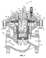
- Fig. 3 is a cross-sectional side view of a regulator constructed in accordance with the present disclosure.
- Fig. 4 is a detailed partial cross-sectional view of a spring seat of the regulator of Fig. 3 .
- the pressure regulator 100 generally includes a valve body 102 and an actuator 106.
- the valve body 102 defines a flow-path 108 extending between an inlet 110 and an outlet 112, as well as into the actuator 106, as will be discussed.
- the actuator 106 includes a control assembly 114 that is moveable between an open position, as is shown in FIG. 3 , and a closed position (not shown), wherein the control assembly 114 engages a seat ring 104 disposed within a throat 116 of the valve body 102. Movement of the control assembly 114 occurs in response to fluctuations in the pressure of the fluid at the inlet 110 and outlet 112. Accordingly, the position of the control assembly 114 relative to the seat ring 104 affects a flow capacity of the pressure regulator 100.
- the actuator 106 includes the control assembly 114 and additionally, an upper actuator casing 122, a lower actuator casing 124, and a cage 126.
- the upper and lower actuator casings 122, 124 are secured together by at least one threaded fastener 119 and corresponding nut 121.
- the upper actuator casing 122 defines a central opening 123, at least one first control inlet 125, and a travel chamber 127.
- the travel chamber 127 contains a travel indicator 131, which indicates the position of the control assembly 114 within the actuator 106.
- the lower actuator casing 124 defines at least one second control inlet 129.
- the control opening 123 receives a cap plate 117, which is secured to the upper actuator casing 122 by at least one threaded fastener 113.
- the upper and lower actuator casings 122, 124 define a cavity 135 in communication with an actuator opening 115 in the valve body 102.
- the cage 126 of the actuator 106 has a first end 126a extending into the cavity 135 and a second end 126b defining the seat ring 104.
- the control assembly 114 includes a diaphragm subassembly 133 and a positioning device assembly 138.
- the positioning device assembly 138 includes a tubular control member 130, a mounting subassembly 132, a central rod 186, a first spring seat 188, a second spring seat 190, and a coil spring 193.
- the tubular control member 130 has a generally cylindrical inner surface 143 and a generally cylindrical outer surface 147.
- the inner surface 143 defines a central bore through the tubular control member 130.
- the tubular control member 130 includes an upper end 130a and a lower end 130b.
- the upper end 130a is disposed within the cavity 135 of the actuator 106 and the lower end 130b is disposed within the cage 126.
- the upper end 130a of the tubular control member 130 is open and includes a circumferential flange 140 formed on the outer surface 147.
- the upper portion 130a of the tubular control member 130 includes a threaded portion 141 on the inner surface 143.
- the lower end 130b of the tubular control member 130 is open and accommodates the mounting subassembly 132.
- the mounting subassembly 132 includes a mounting member 142, a disk retainer 144, a disk holder 146, and a sealing disk 148.
- the mounting member 142 includes a generally cylindrical body threaded into the open lower end 130b of the tubular control member 130 and defining a through-bore 150.
- the through-bore 150 is generally axially aligned with the tubular control member 130.
- the disk retainer 144 includes a generally cylindrical body fixed to the mounting member 142 with a pair of fasteners 152.
- the fasteners 152 include threaded fasteners.
- the disk retainer 144 defines a through-bore 154.
- the through-bore 154 of the disk retainer 144 has a diameter substantially identical to a diameter of the through-bore 150 in the mounting member 142 and is axially aligned therewith.
- the disk retainer 144 secures the disk holder 146 and the sealing disk 148 to the mounting member 142 of the retainer assembly 132.
- the disk holder 146 includes a generally ring-shaped plate constructed of a rigid material such as steel.
- the sealing disk 148 includes a generally ring-shaped disk made of a resilient material and fixed to the disk holder 146. In one form, the sealing disk 148 is fixed to the disk holder 146 with an adhesive.
- the configuration of the disk retainer 144 limits radial deformation of the sealing disk 148 when the control assembly 114 is in a closed position and compressing the sealing disk 148 against the seat ring 104.
- the diaphragm subassembly 133 includes a diaphragm 134, an upper diaphragm plate 136a and a lower diaphragm plate 136b.
- the upper and lower diaphragm plates 136a, 136b are clamped onto the circumferential flange 140 of the tubular control member 130.
- the diaphragm plates 136a, 136b are secured together via fasteners 156, thereby fixing the tubular control member 130 and the diaphragm plates 136a, 136b together.
- diaphragm plates 136a, 136b sandwich a radially inward portion of the diaphragm 134.
- a radially outward portion of the diaphragm 134 is fixed between the upper and lower actuator casings 122, 124.
- the central rod 186, the first and second spring seats 188, 190, and the spring 193 of the positioning device assembly 138 are generally disposed within the tubular control member 130 to bias the tubular control member 130 into the open position depicted in FIG. 3 .
- the central rod 186 includes a first threaded end 186a and a second threaded end 186b.
- the first threaded end 186a extends through the cap plate 117 and a pair of external nuts 194 are threaded onto the first threaded end 186a to limit axial displacement of the central rod 186 in the downward direction relative to the orientation of the regulator 100 depicted in FIG. 3 .
- the central rod 186 further includes a shoulder 196 disposed opposite the cap plate 117 from the external nuts 194 to limit axial displacement of the central rod 186 in the upward direction relative to the orientation of the regulator 100 depicted in FIG. 3 . Accordingly, the first threaded end 186a of the central rod 186 is effectively fixed against axial displacement relative to the cap plate 117, actuator 106, and valve body 102, while the second threaded end 186b extends into the actuator 106.
- the second threaded end 186b of the central rod 186 extends into the tubular control member 130 and is disposed adjacent the second end 130b of the tubular control member 130 for supporting the first spring seat 188.
- the first spring seat 188 includes a generally flat plate that defines a central opening 188a and a plurality of apertures 188b.
- the plurality of apertures 188b are in fluid communication with the flow path 108 through the valve body 102 via the through-bores 150, 154 in the mounting subassembly 132 to facilitate operation of the regulator 100 in a known manner.
- the central opening 188a receives the second end 186b of the central rod 186 at a location adjacent a shoulder 187 formed on the central rod 186.
- a retention nut 198 is threaded onto the second threaded end 186b of the central rod 186 and forces the first spring seat 188 against the shoulder 187 such that the first spring seat 188 is fixed relative to the central rod 186.
- the first spring seat 188 is slidably disposed relative to the tubular control member 130, as will be discussed in more detail below. As illustrated, the first spring seat 188 supports a lower portion 193b of the spring 193 within the tubular control member 130, thereby positioning an upper portion 193a of the spring 193 in engagement with the second spring seat 190.
- the second spring seat 190 of the disclosed embodiment includes two separate and distinct components comprising a spring seat adaptor 200 and a seat ring 202.
- the spring seat adaptor 200 is fixed to the tubular control member 130 and supports the seat ring 202.
- the seat ring 202 is disposed in engagement with the spring seat adaptor 200 and movable relative thereto to self-align the seat ring 202, which in turn self-aligns the spring 193 and the first spring seat 188 within the tubular control member 130 during assembly and operation of the regulator 100.
- the second spring seat 190 including the spring seat adaptor 200 and the seat ring 202, which is a separate and distinct component from the spring seat adaptor 200, is depicted in more detail.
- the spring seat adaptor 200 includes a cross-sectional geometry that generally resembles a modified conical or triangular shape including a fixation portion 204, a seating portion 206, and a rod receiving portion 208.
- the fixation portion 204 is generally cylindrical and includes a plurality of external threads 210 that threadably connect the spring seat adaptor 200 to the plurality of threads 141 on the inner surface 143 of the tubular control member 130, as depicted in Fig. 3 .
- the rod receiving portion 208 is also generally cylindrical and includes an end wall 208a defining an aperture 212 for receiving the central rod 186, as depicted in Fig. 3 , such that the tubular control member 130 and second spring seat 190 can move relative to the central rod 186 during operation of the regulator 100.
- the seating portion 206 of the second spring seat 200 is disposed between the fixation portion 204 and the rod receiving portion 208 and is adapted to be engaged by and movably support the seat ring 202, and therefore, the upper portion 193a of the spring 193 that engages the seat ring 202.
- the seating portion 206 includes a wall extending at an angle between the fixation portion 204 and the rod receiving portion 208, and which defines an external surface 214 for being seated against by the seat ring 202.
- the disclosed embodiment of the seat ring 202 includes a generally L-shaped cross-section defining a seating surface 216, an alignment surface 218, and an internal surface 220.
- the internal surface 220 of the seat ring 202 engages the external surface 214 of the spring seat adaptor 200 and is adapted for displacement relative thereto, as will be discussed.
- the seating and alignment surfaces 216, 218 are disposed at approximately ninety-degrees relative to each other.
- the upper portion 193a of the spring 193 seats against the seating surface 216 of the seat ring 202 and an inner portion 193c of the spring 193 is disposed adjacent to and/or in contact with the alignment surface 218.
- the seat ring 202 of the second spring seat 190 operates to support and align the upper portion 193a of the spring 193 within the tubular control member 130, while the first spring seat 188 supports the lower portion 193b of the spring 193. So configured, the spring 193 is compressed between the first spring seat 188 and the seating surface 216 of the seat ring 202 of the second spring seat 190.
- the seat ring 202 of the second spring seat 190 is movable relative the spring seat adaptor 200.
- the external surface 214 of the spring seat adaptor 200 includes a convex partial spherical surface and the internal surface 220 of the seat ring 202 includes a concave partial spherical surface.
- the external surface 214 and internal surface 220 can have the same radius of curvature.
- the external surface 214 and the internal surface 220 define a ball-and-socket type joint 222 between the spring seat adaptor 200 and the seat ring 202 that allows the seat ring 202 to articulate, pivot, rotate, and otherwise freely move relative to the spring seat adaptor 200.
- the second spring seat 190 of the disclosed regulator 100 advantageously provides a self-aligning function to the seat ring 202, coil spring 193, and first spring seat 188 by enabling the seat ring 202 and the coil spring 193 to move relative to the external surface 214 of the spring seat 190.
- the tubular control member 130 and the second spring seat 190 move up and down relative to the central rod 186 in response to changes in pressure across the diaphragm assembly 133 in the actuator 106.
- This movement causes the spring 193 to cyclically expand and compress as the tubular control member 130 moves toward and away from the valve seat 104 of the cage 126.
- the coil spring 193 has imperfections, the coil spring 193 and/or the first spring seat 188 can undergo side loading due to uneven perimeter loading of the spring 193.
- the movable seat ring 202 of the second spring seat 190 and the movable upper portion 193a of the spring 193, advantageously counteract such perimeter loading by pivoting, articulating, rotating, and otherwise self-adjusting their positions relative to the spring seat adaptor 200 according to the varying perimeter forces generated by the spring 193.
- side loading of the spring 193 and first spring seat 188 can be reduced, which in turn can reduce wear and increase the useful life of the spring 193 and the first spring seat 188.
- Another advantage of the disclosed design is that it provides for easier assembly over conventional designs. Specifically, to assemble the positioning device assembly 138 disclosed herein, a technician can first attach the first spring seat 188 to the second end 186b of the central rod 186 and position the rod 186 into the tubular control member 130. The spring 193 can then be dropped into the tubular controi member 130 and positioned about the rod 186. The seat ring 202 can then be positioned on the spring 193 such that the alignment surface 218 fits into and the seating surface 216 engages the upper portion 193a of the spring 193.
- the technician can then place the aperture 212 in the rod receiving portion 208 of the spring seat adaptor 200 onto the first end 186a of the central rod 186, which will cause the external surface 214 of the seating portion 206 to engage the internal surface 220 of the seat ring 202.
- the threads 210 on the fixation portion 204 of the spring seat adaptor 200 can then be tightened into the threads 141 on the inner surface 143 of the tubular control member 130. While tightening the spring seat adaptor 200 into the tubular control member 130, the spring seat adaptor 200 is rotated relative to the spring 193 and seat ring 202. In conventional designs, the torque applied to the spring seat would transfer directly to the spring, thereby frustrating the alignment of the spring and making tightening of the spring seat difficult, especially when the spring required pre-loading.
- the assembly process of the disclosed positioning device assembly 138 is much easier than conventional positioning device assemblies.
- the spring compression design could be utilized to accomplish various spring set points in the field.
- the cap plate 117 could easily be removed from the upper actuator casing 122, the spring seat adaptor 200 could then be removed from the tubular control member 130, and the seat ring 202 could be replaced with a different seat ring 202 having a different thickness dimension, for example, for pre-loading the spring 193 a different amount.
- the spring 193 itself could be removed and replaced with a different spring having a different spring force.
- the compression of the spring 193 can be adjusted by adjusting the axial position of the second spring seat 190 relative to the tubular control element 130, which can easily be done by partly unthreading or further threading the spring seat adaptor 202 therein.
- the external surface 214 of the spring seat adaptor 200 disclosed herein has been described as being convex partial spherical, and the internal surface 220 of the seat ring 202 has been described as being concave partial spherical with a radius of curvature equal to a radius of curvature of the external surface 214, alternative embodiments could be configured differently.
- the external surface 214 and internal surface 220 could be convex and concave, respectively, but not necessarily partial spherical.
- the radius of curvatures of the external and internal surfaces 214, 220 could be different.
- the radius of curvature of the external surface 214 on the spring seat adaptor 200 could be greater than the radius of curvature of the internal surface 220 of the seat ring 202. So configured, the seat ring 202 could also pivot relative to the spring seat adaptor 200 without creating any friction, but rather, the external surface 214 could advantageously act as a fulcrum, for example.
- the external surface 214 of the spring seat adaptor 200 could be convex, but the internal surface 220 of the seat ring 202 may include a circular edge such that only a line contact between the seat ring 202 and the spring seat adaptor 200 exists.
- the external surface of the spring seat adaptor 200 could be concave or even flat.
- the second spring seat 190 could include an anti-friction component disposed between the seat ring 202 and the spring seat adaptor 200 to reduce friction and facilitate movement of the seat ring 202.
- the anti-friction component could include a nylon ring, for example, or a layer of graphite, a layer of lubricant, a layer of Teflon, etc.
Landscapes
- Engineering & Computer Science (AREA)
- General Engineering & Computer Science (AREA)
- Mechanical Engineering (AREA)
- Control Of Fluid Pressure (AREA)
- Safety Valves (AREA)
- Sliding Valves (AREA)
- Fluid-Driven Valves (AREA)
- Check Valves (AREA)
- Fluid-Damping Devices (AREA)
- Lift Valve (AREA)
- Quick-Acting Or Multi-Walled Pipe Joints (AREA)
Claims (8)
- Ensemble de dispositif de positionnement pour réguler l'écoulement d'un fluide à travers un trajet d'écoulement de fluide d'un régulateur, l'ensemble de dispositif de positionnement comprenant :un élément de commande tubulaire (130) ;une tige centrale (186) disposée au moins partiellement dans l'élément de commande tubulaire (130) et adaptée pour être fixée sur un carter du régulateur (100) ;un premier siège pour ressort (188) disposé dans l'élément de commande tubulaire (130) et fixé par rapport à la tige centrale (186) ;un second siège pour ressort (190) au moins partiellement disposé dans l'élément de commande tubulaire (130) et définissant une ouverture à travers laquelle s'étend la tige centrale (186) ; etun ressort (193) disposé entre les premier (188) et second (190) sièges pour ressort, le ressort (193) étant adapté pour rappeler l'élément de commande tubulaire (130) dans une position prédéterminée par rapport au carter du régulateur (100), caractérisé en ce quele second siège pour ressort (190) comprend un adaptateur de siège pour ressort (200) fixé par rapport à l'élément de commande (130) et une bague de siège (202) venant en contact avec le ressort (193) et adaptée pour se déplacer par rapport à l'adaptateur de siège pour ressort (200) pour ainsi auto-aligner le ressort (193) dans l'élément de commande tubulaire (130).
- Ensemble selon la revendication 1, dans lequel la bague de siège (202) est articulée par rapport à l'adaptateur de siège pour ressort (200).
- Ensemble selon la revendication 1, dans lequel le second siège pour ressort (190) comprend une articulation du type à rotule entre l'adaptateur de siège pour ressort (200) et la bague de siège (202) de sorte que la bague de siège (202) peut être articulée par rapport à l'adaptateur de siège pour ressort (200).
- Ensemble selon la revendication 3, dans lequel l'adaptateur de siège pour ressort (200) comprend une surface convexe sphérique partielle et la bague de siège (202) est en contact avec la surface convexe sphérique partielle de l'adaptateur de siège pour ressort (200).
- Ensemble selon la revendication 4, dans lequel la bague de siège (202) comprend une surface concave sphérique partielle en contact avec la surface convexe sphérique partielle de l'adaptateur de siège pour ressort (200).
- Ensemble selon la revendication 7, comprenant de plus une bague de guidage en nylon disposée entre le premier siège pour ressort (188) et une surface intérieure de l'élément de commande tubulaire (130), la bague de guidage en nylon facilitant un déplacement entre le premier siège pour ressort (188) et l'élément de commande tubulaire (130).
- Ensemble selon la revendication 1, dans lequel l'adaptateur de siège pour ressort (200) du second siège pour ressort (190) est relié de manière vissée à l'élément de commande tubulaire (130).
- Ensemble selon la revendication 1, dans lequel le régulateur comprend :un corps de soupape définissant le trajet d'écoulement de fluide, le carter étant couplé au corps de soupape, et dans lequell'élément de commande tubulaire (130) est au moins partiellement disposé dans le carter et adapté pour se déplacer par rapport au corps de soupape pour réguler l'écoulement de fluide à travers le trajet d'écoulement de fluide.
Applications Claiming Priority (2)
| Application Number | Priority Date | Filing Date | Title |
|---|---|---|---|
| US17301309P | 2009-04-27 | 2009-04-27 | |
| PCT/US2010/031901 WO2010126762A1 (fr) | 2009-04-27 | 2010-04-21 | Siège de ressort à auto-centrage pour régulateur de fluide et régulateur de fluide comprenant un siège de ressort à auto-centrage |
Publications (2)
| Publication Number | Publication Date |
|---|---|
| EP2425157A1 EP2425157A1 (fr) | 2012-03-07 |
| EP2425157B1 true EP2425157B1 (fr) | 2013-02-13 |
Family
ID=42335008
Family Applications (1)
| Application Number | Title | Priority Date | Filing Date |
|---|---|---|---|
| EP20100719471 Active EP2425157B1 (fr) | 2009-04-27 | 2010-04-21 | Siège de ressort à auto-centrage pour régulateur de fluide et régulateur de fluide comprenant un siège de ressort à auto-centrage |
Country Status (10)
| Country | Link |
|---|---|
| US (1) | US8708309B2 (fr) |
| EP (1) | EP2425157B1 (fr) |
| JP (1) | JP5669822B2 (fr) |
| CN (1) | CN102414492B (fr) |
| AR (1) | AR076423A1 (fr) |
| AU (1) | AU2010241860B2 (fr) |
| BR (1) | BRPI1014533B1 (fr) |
| CA (1) | CA2758970C (fr) |
| RU (1) | RU2531545C2 (fr) |
| WO (1) | WO2010126762A1 (fr) |
Families Citing this family (20)
| Publication number | Priority date | Publication date | Assignee | Title |
|---|---|---|---|---|
| CN103671938B (zh) * | 2012-09-21 | 2018-02-13 | 艾默生过程管理调节技术公司 | 自对准阀口 |
| CN103672077B (zh) * | 2012-09-21 | 2018-04-24 | 艾默生过程管理调节技术公司 | 带有入口压强感应管的平衡压强调节器与平衡塞组件 |
| US9200716B2 (en) * | 2012-09-28 | 2015-12-01 | Emerson Process Management Regulator Technologies, Inc. | Self aligning valve plug |
| US9568117B2 (en) | 2012-11-16 | 2017-02-14 | Ge Oil & Gas Pressure Control Lp | Combination diaphragm piston actuator |
| US8991420B2 (en) * | 2012-11-16 | 2015-03-31 | Ge Oil & Gas Pressure Control Lp | Non-rising stem actuator |
| US9759240B2 (en) | 2012-12-31 | 2017-09-12 | Ge Oil & Gas Pressure Control Lp | No-bolt security latching system |
| US11015733B2 (en) | 2012-12-31 | 2021-05-25 | Ge Oil & Gas Pressure Control Lp | No-bolt latching system |
| US10132422B2 (en) | 2012-12-31 | 2018-11-20 | Ge Oil & Gas Pressure Control Lp | Compound express actuator connection |
| US11326712B2 (en) | 2012-12-31 | 2022-05-10 | Baker Hughes Oilfield Operations Llc | No-bolt valve assembly system |
| US10480675B2 (en) | 2012-12-31 | 2019-11-19 | Ge Oil & Gas Pressure Control Lp | No-bolt security latching system |
| US11015732B2 (en) | 2012-12-31 | 2021-05-25 | Ge Oil & Gas Pressure Control Lp | Axially restricted pressure shuttle |
| US9709998B2 (en) | 2013-03-14 | 2017-07-18 | Marshall Excelsior Co. | Pressure regulator |
| US9360120B2 (en) | 2013-11-01 | 2016-06-07 | Emerson Process Management Regulator Technologies, Inc. | Valve plug for pressure regulator |
| US9739381B2 (en) | 2013-11-01 | 2017-08-22 | Emerson Process Management Regulator Technologies, Inc. | Mechanically retained valve seat |
| DE202017104079U1 (de) * | 2017-07-07 | 2017-08-21 | Samson Ag | Stellantrieb für Prozessventile |
| US10823293B2 (en) | 2018-07-23 | 2020-11-03 | Emerson Vulcan Holding Llc | Valve disc assemblies for fluid valves having soft seats |
| CN109469735B (zh) * | 2018-12-11 | 2023-10-27 | 四川长仪油气集输设备股份有限公司 | 一种双阀口三密封阀芯阀座结构 |
| US11466783B2 (en) | 2020-03-25 | 2022-10-11 | Baker Hughes Oilfield Operations Llc | Side entry valve |
| US11920687B2 (en) | 2020-03-25 | 2024-03-05 | Baker Hughes Oilfield Operations Llc | Valve end replacement system and method |
| US12435595B2 (en) * | 2023-02-02 | 2025-10-07 | Worldwide Oilfield Machine, Inc. | BOP piston booster and bonnet assembly |
Family Cites Families (16)
| Publication number | Priority date | Publication date | Assignee | Title |
|---|---|---|---|---|
| US8007A (en) * | 1851-04-01 | crosby | ||
| US2492465A (en) * | 1947-05-16 | 1949-12-27 | Hammel Dahl Company | Pressure responsive device |
| GB1254106A (en) * | 1968-03-26 | 1971-11-17 | Telektron Ltd | Pressure regulating valve |
| DE1750118C3 (de) * | 1968-03-30 | 1974-07-18 | Samson Apparatebau Ag, 6000 Frankfurt | Ventil od.dgl. mit umkehrbarer Druckmittelbetätigung |
| SU549633A1 (ru) * | 1975-12-11 | 1977-03-05 | Горловский Государственный Рудоремонтный Завод | Клапан |
| US5279327A (en) * | 1992-08-31 | 1994-01-18 | Orbital Walbro Corporation | Pressure regulator |
| JPH11129721A (ja) * | 1997-10-31 | 1999-05-18 | Chuo Spring Co Ltd | 車両懸架装置 |
| ITBO20010317A1 (it) * | 2001-05-21 | 2002-11-21 | Hydrocontrol Spa | Valvola di abilitazione dei comandi di un attuatore fluidodinamico |
| CN1325828C (zh) * | 2001-10-29 | 2007-07-11 | 伯尔梅特合伙有限公司 | 滚动膜片控制阀 |
| JP4055845B2 (ja) * | 2002-05-08 | 2008-03-05 | 株式会社ショーワ | 油圧緩衝器のダストカバー受け構造 |
| US6959913B2 (en) * | 2003-06-13 | 2005-11-01 | Dynamic Air Inc. | Actuator |
| ITBO20050197A1 (it) * | 2005-03-25 | 2006-09-26 | Omt Off Mecc Tartarini | Regolatore di pressione per gas e relativo metodo di montaggio e smontaggio |
| RU53397U1 (ru) * | 2005-12-21 | 2006-05-10 | Открытое Акционерное Общество "Государственное Машиностроительное Конструкторское Бюро "Радуга" Имени А.Я. Березняка" | Клапан |
| JP2008101765A (ja) | 2006-09-20 | 2008-05-01 | Fuji Koki Corp | 電動弁 |
| US8826933B2 (en) * | 2006-09-29 | 2014-09-09 | Fisher Controls International Llc | Positioning device for pressure regulator |
| US7954788B2 (en) * | 2007-07-16 | 2011-06-07 | Fisher Controls International, Llc | Methods and apparatus to align a seat ring in a valve |
-
2010
- 2010-04-21 AU AU2010241860A patent/AU2010241860B2/en active Active
- 2010-04-21 CA CA2758970A patent/CA2758970C/fr active Active
- 2010-04-21 WO PCT/US2010/031901 patent/WO2010126762A1/fr not_active Ceased
- 2010-04-21 EP EP20100719471 patent/EP2425157B1/fr active Active
- 2010-04-21 CN CN201080018568.6A patent/CN102414492B/zh active Active
- 2010-04-21 BR BRPI1014533-8A patent/BRPI1014533B1/pt not_active IP Right Cessation
- 2010-04-21 RU RU2011145892/06A patent/RU2531545C2/ru active
- 2010-04-21 US US12/764,712 patent/US8708309B2/en active Active
- 2010-04-21 JP JP2012507353A patent/JP5669822B2/ja active Active
- 2010-04-26 AR ARP100101392 patent/AR076423A1/es active IP Right Grant
Also Published As
| Publication number | Publication date |
|---|---|
| AR076423A1 (es) | 2011-06-08 |
| WO2010126762A1 (fr) | 2010-11-04 |
| CA2758970A1 (fr) | 2010-11-04 |
| RU2011145892A (ru) | 2013-06-10 |
| CN102414492A (zh) | 2012-04-11 |
| BRPI1014533A2 (pt) | 2016-04-05 |
| AU2010241860A1 (en) | 2011-11-10 |
| BRPI1014533B1 (pt) | 2020-10-20 |
| US20100269925A1 (en) | 2010-10-28 |
| EP2425157A1 (fr) | 2012-03-07 |
| JP5669822B2 (ja) | 2015-02-18 |
| AU2010241860B2 (en) | 2016-08-04 |
| CA2758970C (fr) | 2016-02-16 |
| RU2531545C2 (ru) | 2014-10-20 |
| CN102414492B (zh) | 2014-07-16 |
| JP2012525544A (ja) | 2012-10-22 |
| US8708309B2 (en) | 2014-04-29 |
Similar Documents
| Publication | Publication Date | Title |
|---|---|---|
| EP2425157B1 (fr) | Siège de ressort à auto-centrage pour régulateur de fluide et régulateur de fluide comprenant un siège de ressort à auto-centrage | |
| US11047483B2 (en) | Valve with self-aligning stem tip | |
| EP2577131B1 (fr) | Siège de ressort destiné à être utilisé avec des actionneurs | |
| US9091366B2 (en) | Flow restricted seat ring for pressure regulators | |
| CN101517293B (zh) | 用于压力调节阀的定位装置 | |
| EP2898240B1 (fr) | Orifice de soupape à alignement automatique | |
| US8590858B2 (en) | Anti-gradient cupped seat for pressure regulator | |
| US9874883B2 (en) | Diaphragm interface apparatus to improve a cycle life of a diaphragm | |
| KR101736022B1 (ko) | 축방향으로 구속된 자가 정렬식 조절기 밸브 조립체 | |
| JP2015532480A (ja) | 自動調心弁体 | |
| CN203023521U (zh) | 流体调节装置以及用于流体调节装置的自对准阀口 | |
| US20260029807A1 (en) | Pressure regulators with pivotable valve disk assemblies |
Legal Events
| Date | Code | Title | Description |
|---|---|---|---|
| PUAI | Public reference made under article 153(3) epc to a published international application that has entered the european phase |
Free format text: ORIGINAL CODE: 0009012 |
|
| 17P | Request for examination filed |
Effective date: 20111114 |
|
| AK | Designated contracting states |
Kind code of ref document: A1 Designated state(s): AT BE BG CH CY CZ DE DK EE ES FI FR GB GR HR HU IE IS IT LI LT LU LV MC MK MT NL NO PL PT RO SE SI SK SM TR |
|
| DAX | Request for extension of the european patent (deleted) | ||
| GRAP | Despatch of communication of intention to grant a patent |
Free format text: ORIGINAL CODE: EPIDOSNIGR1 |
|
| GRAS | Grant fee paid |
Free format text: ORIGINAL CODE: EPIDOSNIGR3 |
|
| GRAA | (expected) grant |
Free format text: ORIGINAL CODE: 0009210 |
|
| AK | Designated contracting states |
Kind code of ref document: B1 Designated state(s): AT BE BG CH CY CZ DE DK EE ES FI FR GB GR HR HU IE IS IT LI LT LU LV MC MK MT NL NO PL PT RO SE SI SK SM TR |
|
| REG | Reference to a national code |
Ref country code: GB Ref legal event code: FG4D |
|
| REG | Reference to a national code |
Ref country code: AT Ref legal event code: REF Ref document number: 596681 Country of ref document: AT Kind code of ref document: T Effective date: 20130215 |
|
| REG | Reference to a national code |
Ref country code: IE Ref legal event code: FG4D |
|
| REG | Reference to a national code |
Ref country code: DE Ref legal event code: R096 Ref document number: 602010005023 Country of ref document: DE Effective date: 20130411 |
|
| REG | Reference to a national code |
Ref country code: AT Ref legal event code: MK05 Ref document number: 596681 Country of ref document: AT Kind code of ref document: T Effective date: 20130213 |
|
| REG | Reference to a national code |
Ref country code: NL Ref legal event code: VDEP Effective date: 20130213 |
|
| REG | Reference to a national code |
Ref country code: LT Ref legal event code: MG4D |
|
| PG25 | Lapsed in a contracting state [announced via postgrant information from national office to epo] |
Ref country code: NO Free format text: LAPSE BECAUSE OF FAILURE TO SUBMIT A TRANSLATION OF THE DESCRIPTION OR TO PAY THE FEE WITHIN THE PRESCRIBED TIME-LIMIT Effective date: 20130513 Ref country code: LT Free format text: LAPSE BECAUSE OF FAILURE TO SUBMIT A TRANSLATION OF THE DESCRIPTION OR TO PAY THE FEE WITHIN THE PRESCRIBED TIME-LIMIT Effective date: 20130213 Ref country code: IS Free format text: LAPSE BECAUSE OF FAILURE TO SUBMIT A TRANSLATION OF THE DESCRIPTION OR TO PAY THE FEE WITHIN THE PRESCRIBED TIME-LIMIT Effective date: 20130613 Ref country code: AT Free format text: LAPSE BECAUSE OF FAILURE TO SUBMIT A TRANSLATION OF THE DESCRIPTION OR TO PAY THE FEE WITHIN THE PRESCRIBED TIME-LIMIT Effective date: 20130213 Ref country code: SE Free format text: LAPSE BECAUSE OF FAILURE TO SUBMIT A TRANSLATION OF THE DESCRIPTION OR TO PAY THE FEE WITHIN THE PRESCRIBED TIME-LIMIT Effective date: 20130213 Ref country code: ES Free format text: LAPSE BECAUSE OF FAILURE TO SUBMIT A TRANSLATION OF THE DESCRIPTION OR TO PAY THE FEE WITHIN THE PRESCRIBED TIME-LIMIT Effective date: 20130524 Ref country code: BG Free format text: LAPSE BECAUSE OF FAILURE TO SUBMIT A TRANSLATION OF THE DESCRIPTION OR TO PAY THE FEE WITHIN THE PRESCRIBED TIME-LIMIT Effective date: 20130513 |
|
| PG25 | Lapsed in a contracting state [announced via postgrant information from national office to epo] |
Ref country code: PT Free format text: LAPSE BECAUSE OF FAILURE TO SUBMIT A TRANSLATION OF THE DESCRIPTION OR TO PAY THE FEE WITHIN THE PRESCRIBED TIME-LIMIT Effective date: 20130613 Ref country code: FI Free format text: LAPSE BECAUSE OF FAILURE TO SUBMIT A TRANSLATION OF THE DESCRIPTION OR TO PAY THE FEE WITHIN THE PRESCRIBED TIME-LIMIT Effective date: 20130213 Ref country code: SI Free format text: LAPSE BECAUSE OF FAILURE TO SUBMIT A TRANSLATION OF THE DESCRIPTION OR TO PAY THE FEE WITHIN THE PRESCRIBED TIME-LIMIT Effective date: 20130213 Ref country code: LV Free format text: LAPSE BECAUSE OF FAILURE TO SUBMIT A TRANSLATION OF THE DESCRIPTION OR TO PAY THE FEE WITHIN THE PRESCRIBED TIME-LIMIT Effective date: 20130213 Ref country code: GR Free format text: LAPSE BECAUSE OF FAILURE TO SUBMIT A TRANSLATION OF THE DESCRIPTION OR TO PAY THE FEE WITHIN THE PRESCRIBED TIME-LIMIT Effective date: 20130514 Ref country code: PL Free format text: LAPSE BECAUSE OF FAILURE TO SUBMIT A TRANSLATION OF THE DESCRIPTION OR TO PAY THE FEE WITHIN THE PRESCRIBED TIME-LIMIT Effective date: 20130213 Ref country code: BE Free format text: LAPSE BECAUSE OF FAILURE TO SUBMIT A TRANSLATION OF THE DESCRIPTION OR TO PAY THE FEE WITHIN THE PRESCRIBED TIME-LIMIT Effective date: 20130213 |
|
| PG25 | Lapsed in a contracting state [announced via postgrant information from national office to epo] |
Ref country code: HR Free format text: LAPSE BECAUSE OF FAILURE TO SUBMIT A TRANSLATION OF THE DESCRIPTION OR TO PAY THE FEE WITHIN THE PRESCRIBED TIME-LIMIT Effective date: 20130213 |
|
| PG25 | Lapsed in a contracting state [announced via postgrant information from national office to epo] |
Ref country code: EE Free format text: LAPSE BECAUSE OF FAILURE TO SUBMIT A TRANSLATION OF THE DESCRIPTION OR TO PAY THE FEE WITHIN THE PRESCRIBED TIME-LIMIT Effective date: 20130213 Ref country code: CZ Free format text: LAPSE BECAUSE OF FAILURE TO SUBMIT A TRANSLATION OF THE DESCRIPTION OR TO PAY THE FEE WITHIN THE PRESCRIBED TIME-LIMIT Effective date: 20130213 Ref country code: SK Free format text: LAPSE BECAUSE OF FAILURE TO SUBMIT A TRANSLATION OF THE DESCRIPTION OR TO PAY THE FEE WITHIN THE PRESCRIBED TIME-LIMIT Effective date: 20130213 Ref country code: NL Free format text: LAPSE BECAUSE OF FAILURE TO SUBMIT A TRANSLATION OF THE DESCRIPTION OR TO PAY THE FEE WITHIN THE PRESCRIBED TIME-LIMIT Effective date: 20130213 Ref country code: DK Free format text: LAPSE BECAUSE OF FAILURE TO SUBMIT A TRANSLATION OF THE DESCRIPTION OR TO PAY THE FEE WITHIN THE PRESCRIBED TIME-LIMIT Effective date: 20130213 Ref country code: RO Free format text: LAPSE BECAUSE OF FAILURE TO SUBMIT A TRANSLATION OF THE DESCRIPTION OR TO PAY THE FEE WITHIN THE PRESCRIBED TIME-LIMIT Effective date: 20130213 |
|
| PG25 | Lapsed in a contracting state [announced via postgrant information from national office to epo] |
Ref country code: MC Free format text: LAPSE BECAUSE OF FAILURE TO SUBMIT A TRANSLATION OF THE DESCRIPTION OR TO PAY THE FEE WITHIN THE PRESCRIBED TIME-LIMIT Effective date: 20130213 |
|
| PLBE | No opposition filed within time limit |
Free format text: ORIGINAL CODE: 0009261 |
|
| STAA | Information on the status of an ep patent application or granted ep patent |
Free format text: STATUS: NO OPPOSITION FILED WITHIN TIME LIMIT |
|
| 26N | No opposition filed |
Effective date: 20131114 |
|
| REG | Reference to a national code |
Ref country code: IE Ref legal event code: MM4A |
|
| REG | Reference to a national code |
Ref country code: DE Ref legal event code: R097 Ref document number: 602010005023 Country of ref document: DE Effective date: 20131114 |
|
| PG25 | Lapsed in a contracting state [announced via postgrant information from national office to epo] |
Ref country code: IE Free format text: LAPSE BECAUSE OF NON-PAYMENT OF DUE FEES Effective date: 20130421 |
|
| REG | Reference to a national code |
Ref country code: CH Ref legal event code: PL |
|
| PG25 | Lapsed in a contracting state [announced via postgrant information from national office to epo] |
Ref country code: CH Free format text: LAPSE BECAUSE OF NON-PAYMENT OF DUE FEES Effective date: 20140430 Ref country code: LI Free format text: LAPSE BECAUSE OF NON-PAYMENT OF DUE FEES Effective date: 20140430 |
|
| PG25 | Lapsed in a contracting state [announced via postgrant information from national office to epo] |
Ref country code: MT Free format text: LAPSE BECAUSE OF FAILURE TO SUBMIT A TRANSLATION OF THE DESCRIPTION OR TO PAY THE FEE WITHIN THE PRESCRIBED TIME-LIMIT Effective date: 20130213 |
|
| PG25 | Lapsed in a contracting state [announced via postgrant information from national office to epo] |
Ref country code: SM Free format text: LAPSE BECAUSE OF FAILURE TO SUBMIT A TRANSLATION OF THE DESCRIPTION OR TO PAY THE FEE WITHIN THE PRESCRIBED TIME-LIMIT Effective date: 20130213 |
|
| PG25 | Lapsed in a contracting state [announced via postgrant information from national office to epo] |
Ref country code: TR Free format text: LAPSE BECAUSE OF FAILURE TO SUBMIT A TRANSLATION OF THE DESCRIPTION OR TO PAY THE FEE WITHIN THE PRESCRIBED TIME-LIMIT Effective date: 20130213 Ref country code: CY Free format text: LAPSE BECAUSE OF FAILURE TO SUBMIT A TRANSLATION OF THE DESCRIPTION OR TO PAY THE FEE WITHIN THE PRESCRIBED TIME-LIMIT Effective date: 20130213 |
|
| PG25 | Lapsed in a contracting state [announced via postgrant information from national office to epo] |
Ref country code: LU Free format text: LAPSE BECAUSE OF NON-PAYMENT OF DUE FEES Effective date: 20130421 Ref country code: MK Free format text: LAPSE BECAUSE OF FAILURE TO SUBMIT A TRANSLATION OF THE DESCRIPTION OR TO PAY THE FEE WITHIN THE PRESCRIBED TIME-LIMIT Effective date: 20130213 Ref country code: HU Free format text: LAPSE BECAUSE OF FAILURE TO SUBMIT A TRANSLATION OF THE DESCRIPTION OR TO PAY THE FEE WITHIN THE PRESCRIBED TIME-LIMIT; INVALID AB INITIO Effective date: 20100421 |
|
| REG | Reference to a national code |
Ref country code: FR Ref legal event code: PLFP Year of fee payment: 7 |
|
| REG | Reference to a national code |
Ref country code: FR Ref legal event code: PLFP Year of fee payment: 8 |
|
| REG | Reference to a national code |
Ref country code: FR Ref legal event code: PLFP Year of fee payment: 9 |
|
| PGFP | Annual fee paid to national office [announced via postgrant information from national office to epo] |
Ref country code: GB Payment date: 20200323 Year of fee payment: 11 |
|
| GBPC | Gb: european patent ceased through non-payment of renewal fee |
Effective date: 20210421 |
|
| PG25 | Lapsed in a contracting state [announced via postgrant information from national office to epo] |
Ref country code: GB Free format text: LAPSE BECAUSE OF NON-PAYMENT OF DUE FEES Effective date: 20210421 |
|
| P01 | Opt-out of the competence of the unified patent court (upc) registered |
Effective date: 20230526 |
|
| PGFP | Annual fee paid to national office [announced via postgrant information from national office to epo] |
Ref country code: FR Payment date: 20250319 Year of fee payment: 16 |
|
| PGFP | Annual fee paid to national office [announced via postgrant information from national office to epo] |
Ref country code: IT Payment date: 20250319 Year of fee payment: 16 |
|
| PGFP | Annual fee paid to national office [announced via postgrant information from national office to epo] |
Ref country code: DE Payment date: 20250319 Year of fee payment: 16 |