EP2425124B1 - Underwater power plant comprising a water turbine with bidirectional fluid flow and unidirectional rotation - Google Patents
Underwater power plant comprising a water turbine with bidirectional fluid flow and unidirectional rotation Download PDFInfo
- Publication number
- EP2425124B1 EP2425124B1 EP10718061A EP10718061A EP2425124B1 EP 2425124 B1 EP2425124 B1 EP 2425124B1 EP 10718061 A EP10718061 A EP 10718061A EP 10718061 A EP10718061 A EP 10718061A EP 2425124 B1 EP2425124 B1 EP 2425124B1
- Authority
- EP
- European Patent Office
- Prior art keywords
- turbine
- radially
- blades
- power plant
- swivel
- Prior art date
- Legal status (The legal status is an assumption and is not a legal conclusion. Google has not performed a legal analysis and makes no representation as to the accuracy of the status listed.)
- Not-in-force
Links
Images


Classifications
-
- F—MECHANICAL ENGINEERING; LIGHTING; HEATING; WEAPONS; BLASTING
- F03—MACHINES OR ENGINES FOR LIQUIDS; WIND, SPRING, OR WEIGHT MOTORS; PRODUCING MECHANICAL POWER OR A REACTIVE PROPULSIVE THRUST, NOT OTHERWISE PROVIDED FOR
- F03B—MACHINES OR ENGINES FOR LIQUIDS
- F03B13/00—Adaptations of machines or engines for special use; Combinations of machines or engines with driving or driven apparatus; Power stations or aggregates
- F03B13/12—Adaptations of machines or engines for special use; Combinations of machines or engines with driving or driven apparatus; Power stations or aggregates characterised by using wave or tide energy
- F03B13/26—Adaptations of machines or engines for special use; Combinations of machines or engines with driving or driven apparatus; Power stations or aggregates characterised by using wave or tide energy using tide energy
- F03B13/264—Adaptations of machines or engines for special use; Combinations of machines or engines with driving or driven apparatus; Power stations or aggregates characterised by using wave or tide energy using tide energy using the horizontal flow of water resulting from tide movement
-
- F—MECHANICAL ENGINEERING; LIGHTING; HEATING; WEAPONS; BLASTING
- F03—MACHINES OR ENGINES FOR LIQUIDS; WIND, SPRING, OR WEIGHT MOTORS; PRODUCING MECHANICAL POWER OR A REACTIVE PROPULSIVE THRUST, NOT OTHERWISE PROVIDED FOR
- F03B—MACHINES OR ENGINES FOR LIQUIDS
- F03B13/00—Adaptations of machines or engines for special use; Combinations of machines or engines with driving or driven apparatus; Power stations or aggregates
- F03B13/12—Adaptations of machines or engines for special use; Combinations of machines or engines with driving or driven apparatus; Power stations or aggregates characterised by using wave or tide energy
- F03B13/14—Adaptations of machines or engines for special use; Combinations of machines or engines with driving or driven apparatus; Power stations or aggregates characterised by using wave or tide energy using wave energy
- F03B13/24—Adaptations of machines or engines for special use; Combinations of machines or engines with driving or driven apparatus; Power stations or aggregates characterised by using wave or tide energy using wave energy to produce a flow of air, e.g. to drive an air turbine
-
- F—MECHANICAL ENGINEERING; LIGHTING; HEATING; WEAPONS; BLASTING
- F03—MACHINES OR ENGINES FOR LIQUIDS; WIND, SPRING, OR WEIGHT MOTORS; PRODUCING MECHANICAL POWER OR A REACTIVE PROPULSIVE THRUST, NOT OTHERWISE PROVIDED FOR
- F03B—MACHINES OR ENGINES FOR LIQUIDS
- F03B3/00—Machines or engines of reaction type; Parts or details peculiar thereto
- F03B3/12—Blades; Blade-carrying rotors
- F03B3/14—Rotors having adjustable blades
- F03B3/145—Mechanisms for adjusting the blades
-
- F—MECHANICAL ENGINEERING; LIGHTING; HEATING; WEAPONS; BLASTING
- F05—INDEXING SCHEMES RELATING TO ENGINES OR PUMPS IN VARIOUS SUBCLASSES OF CLASSES F01-F04
- F05B—INDEXING SCHEME RELATING TO WIND, SPRING, WEIGHT, INERTIA OR LIKE MOTORS, TO MACHINES OR ENGINES FOR LIQUIDS COVERED BY SUBCLASSES F03B, F03D AND F03G
- F05B2210/00—Working fluid
- F05B2210/40—Flow geometry or direction
- F05B2210/404—Flow geometry or direction bidirectional, i.e. in opposite, alternating directions
-
- F—MECHANICAL ENGINEERING; LIGHTING; HEATING; WEAPONS; BLASTING
- F05—INDEXING SCHEMES RELATING TO ENGINES OR PUMPS IN VARIOUS SUBCLASSES OF CLASSES F01-F04
- F05B—INDEXING SCHEME RELATING TO WIND, SPRING, WEIGHT, INERTIA OR LIKE MOTORS, TO MACHINES OR ENGINES FOR LIQUIDS COVERED BY SUBCLASSES F03B, F03D AND F03G
- F05B2240/00—Components
- F05B2240/20—Rotors
- F05B2240/30—Characteristics of rotor blades, i.e. of any element transforming dynamic fluid energy to or from rotational energy and being attached to a rotor
- F05B2240/31—Characteristics of rotor blades, i.e. of any element transforming dynamic fluid energy to or from rotational energy and being attached to a rotor of changeable form or shape
-
- F—MECHANICAL ENGINEERING; LIGHTING; HEATING; WEAPONS; BLASTING
- F05—INDEXING SCHEMES RELATING TO ENGINES OR PUMPS IN VARIOUS SUBCLASSES OF CLASSES F01-F04
- F05B—INDEXING SCHEME RELATING TO WIND, SPRING, WEIGHT, INERTIA OR LIKE MOTORS, TO MACHINES OR ENGINES FOR LIQUIDS COVERED BY SUBCLASSES F03B, F03D AND F03G
- F05B2260/00—Function
- F05B2260/70—Adjusting of angle of incidence or attack of rotating blades
- F05B2260/74—Adjusting of angle of incidence or attack of rotating blades by turning around an axis perpendicular the rotor centre line
-
- F—MECHANICAL ENGINEERING; LIGHTING; HEATING; WEAPONS; BLASTING
- F05—INDEXING SCHEMES RELATING TO ENGINES OR PUMPS IN VARIOUS SUBCLASSES OF CLASSES F01-F04
- F05B—INDEXING SCHEME RELATING TO WIND, SPRING, WEIGHT, INERTIA OR LIKE MOTORS, TO MACHINES OR ENGINES FOR LIQUIDS COVERED BY SUBCLASSES F03B, F03D AND F03G
- F05B2260/00—Function
- F05B2260/70—Adjusting of angle of incidence or attack of rotating blades
- F05B2260/75—Adjusting of angle of incidence or attack of rotating blades the adjusting mechanism not using auxiliary power sources, e.g. servos
-
- Y—GENERAL TAGGING OF NEW TECHNOLOGICAL DEVELOPMENTS; GENERAL TAGGING OF CROSS-SECTIONAL TECHNOLOGIES SPANNING OVER SEVERAL SECTIONS OF THE IPC; TECHNICAL SUBJECTS COVERED BY FORMER USPC CROSS-REFERENCE ART COLLECTIONS [XRACs] AND DIGESTS
- Y02—TECHNOLOGIES OR APPLICATIONS FOR MITIGATION OR ADAPTATION AGAINST CLIMATE CHANGE
- Y02E—REDUCTION OF GREENHOUSE GAS [GHG] EMISSIONS, RELATED TO ENERGY GENERATION, TRANSMISSION OR DISTRIBUTION
- Y02E10/00—Energy generation through renewable energy sources
- Y02E10/20—Hydro energy
-
- Y—GENERAL TAGGING OF NEW TECHNOLOGICAL DEVELOPMENTS; GENERAL TAGGING OF CROSS-SECTIONAL TECHNOLOGIES SPANNING OVER SEVERAL SECTIONS OF THE IPC; TECHNICAL SUBJECTS COVERED BY FORMER USPC CROSS-REFERENCE ART COLLECTIONS [XRACs] AND DIGESTS
- Y02—TECHNOLOGIES OR APPLICATIONS FOR MITIGATION OR ADAPTATION AGAINST CLIMATE CHANGE
- Y02E—REDUCTION OF GREENHOUSE GAS [GHG] EMISSIONS, RELATED TO ENERGY GENERATION, TRANSMISSION OR DISTRIBUTION
- Y02E10/00—Energy generation through renewable energy sources
- Y02E10/30—Energy from the sea, e.g. using wave energy or salinity gradient
Definitions
- the invention relates to an underwater power plant with a bidirectionally flowable, in the same direction rotating water turbine, in particular a Wellsturbine, and a method for its operation, wherein the underwater power plant is preferably used to exploit a tidal current.
- Subject of a continuation of the invention is a bidirectional air turbine.
- Free-standing placed in an ambient flow underwater power plants represent a cost-effective variant for the energy from a sea current, in particular a tidal current, known.
- a sea current in particular a tidal current
- known propeller-shaped water turbines which rotate on a nacelle, which receives an electric generator inside.
- the electric generator is arranged on the radially outer periphery of the water turbine, that is to say the peripheral unit of the water turbine comprises a generator rotor which lies radially outward with respect to the turbine blades of the water turbine and circulates in an annular support structure.
- the water turbine can be tracked with the flow, typically the entire nacelle of an underwater power plant with the turbine-generator unit is rotated into the flow.
- Such an embodiment is structurally complex and entails that the outgoing from the electrical generator connection cable is to be protected against twisting.
- the rotor blades are equipped with an active blade angle adjustment mechanism that allows the blade profile to rotate 180 °.
- the invention has for its object to make an underwater power plant with a bi-directionally flowable, co-rotating water turbine so that the above problems are overcome.
- an operation at low flow velocities or high velocity fluctuations in the flow should be possible.
- the water turbine is to be designed in such a way that the associated diffuser can be structurally simplified or omitted altogether.
- the water turbine should not tend to stall even at low speeds and be improved in terms of their startup behavior.
- the turbine design should be transferable to a bidirectionally flowable air turbine, in particular for an OWC wave power plant.
- the object underlying the invention is solved by the features of the independent claim.
- the inventors have recognized that a generic turbine of an underwater power plant is assigned to a passive Blattwinkelverstellmechanismus with a pivot axis which lies on the chord between the upstream profile nose and the Auf Georgdelline the hydrodynamic centers.
- a certain angle is set against the plane of rotation.
- the turbine blade will move out of the rotor plane in the direction of the feathering position in the case of large hydrodynamic forces and with a small number of revolutions.
- Under the flag position is understood that an angle between the chord and the plane of rotation occurs, which essentially leads the angle of attack of the profile against the effective flow to zero.
- the pivot axis of the passive blade angle adjustment mechanism may be constructively defined by either a pivotal articulation of the turbine blade on the rotating unit of the water turbine, or the blade will be torsionally resilient, with the stiffeners of the turbine blade defining a torsional axis that faces the upstream lobe profile upstream of the hydrodynamic center's threading line is relocated.
- the hydrodynamic force acting on the hydrodynamic center of the respective profile section generates a swiveling moment caused by centrifugal forces and elastic restoring forces is balanced.
- the latter can either be generated in the turbine blade itself, this is the case in particular in a torsionally elastic designed turbine blade, or at the base of a turbine blade pivotally hinged to a support structure, a device is provided which causes against an upward pivoting of the blade, elastic forces.
- a system of restoring springs is conceivable.
- the passive blade angle adjustment mechanism Due to the passive blade angle adjustment mechanism, a predetermined pivoting of the turbine blade out of the plane of rotation is possible depending on the number of fast-running numbers present. This reduces the necessary for efficient operation circulation speeds of the generic water turbine and already leads for normal operation to an increase in efficiency. In addition, the downsizing of the upstream and downstream nozzles, respectively, provides a further increase in efficiency. In addition, the passive blade angle adjustment mechanism allows expansion of the working area, stalling for fluctuating flow. Furthermore, the pivoted position of the turbine blades allows a simplification of the start-up, so that the transition from the motor drive by means of the electric generator for driving through the hydrodynamic forces on the water turbine can be done earlier in the system start. In addition, by a sufficiently wide pivoting of the turbine blades in the direction of the feathering position, a reduction of the system when reaching the rated power can be effected.
- a speed control of the water turbine is provided for influencing the angle of attack of the turbine blades, which is effected by the electric generator.
- a load torque can be specified by the electric generator.
- the control or the control of the generator is carried out without a fault-prone external sensor and without recourse to characteristics. Instead, we do a search of the maximum of the output power delivered by the electric generator. Particularly preferred For this a MPP controller (Maximum Power Point - MPP) is used. This gives a manipulated variable for the electric generator directly connected to the water turbine with a time variation. This is either the circulating speed impressed by the electric generator or the load torque transmitted to the water turbine and caused by the electric generator.
- the degree of pivoting in the radially outer regions of the turbine blades relative to the radially inner regions to change, in particular to reduce. Due to the radius-dependent peripheral speed, the angle of the effective flow against the plane of rotation is greater at the radially inner regions of the turbine blade. Accordingly, in this area, a stronger pivoting compared to the turbine blade tips is necessary.
- it is therefore intended to form the turbine blades starting from an outer support ring with a radially inwardly directed extension and at the same time to form the turbine blades either in a multi-segment or torsionally-elastic manner.
- the associated pivot axis is in turn between the desired profile nose and the Auf Georgdelline the hydrodynamic centers.
- stiffening elements are provided in the profile that define the Torslonsachse. According to the terminology used in the application thus creates a defined pivot axis.
- the individual segments form radial sections of the turbine blade, which are each rotatable relative to each other about a pivot axis, with the possibility of the maximum To limit tilt angle between two successive segments by suitably designed stop elements.
- the turbine blades designed according to the invention are fastened to a radially outer rim and a radially inner hub, wherein the turbine blade can not be swung radially outward compared to the radially inner part or only up to a smaller pivot angle.
- One possibility is a torsionally elastic design of the turbine blade with a rigid attachment of the turbine blade to the radially outer rim, so that the profiles are there with respect to their chords in the plane of rotation. If a blade designed in this way is pivoted radially inward on the hub, a stable guidance and at the same time the desired radius-dependent pivoting of the turbine blades results.
- the embodiment is transmitted with a radius-dependent pivot angle to an air turbine, which is intended in particular for use in an OWC wave power plant.
- the air turbine comprises a plurality of turbine blades, which have a drop-shaped profile over at least part of their longitudinal extent, wherein the air turbine rotates in the same direction in bidirectional flow.
- a passive blade angle adjustment mechanism is provided for the turbine blades, wherein each turbine blade is associated with a pivot axis which lies between the impinged nose and the center line of the aerodynamic centers, and wherein in operation the Aufschwenkwinkel is smaller in the radially outer regions of the turbine blade in comparison to the radially inner areas.
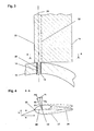
- FIG. 1 shows an underwater power plant 1 in partial sectional view.
- an outer housing 2 is used which is supported by a support structure 10.
- a support structure 10 which is supported by a support structure 10.
- embodiments are conceivable that are buoyant without a support structure 10 by buoyancy elements, in particular in the outer housing 2.
- the inner wall 3 of the outer housing 2 forms a flow channel 4, wherein the inner wall 3 is preferably designed as Konfusor / diffuser combination for flow acceleration, Within the housing 2 is a central element 5, in which the storage of water turbines and the electric generator 40 is arranged are. This will be explained in detail below FIG. 2 explained.
- FIG. 1 an underwater power plant with a first turbine stage 6.1 and a second turbine stage 6.2.
- the first turbine stage 6.1 comprises the guide vanes of the first stage 7.1, 7.2 and the turbine blades of the first stage 11.1, 11.2. 11.3.
- the second turbine stage 6.2 comprises the second stage stator blades 8.1, 8.2, 8.3 and the second stage turbine blades 12.1, 12.2.
- Both turbine stages 6.1, 6.2 are associated with the vanes of the central distributor 9.1, 9.2, 9.3, which are arranged between the turbine blades of the first stage 11.1, 11.2 and the turbine blades of the second stage 12.1, 12.2, 12.3 and which serve in the two-stage Arrangement to reduce the swirl, which is generated by the turbine blades of the respective preceding stage, so that the turbine blades of both stages are flown as consistently as possible.
- FIG. 2 which explains an enlarged section of FIG. 1 represents in the region of the central element 5.
- the same reference numerals are used for matching components.
- the turbine blades of the first stage 11.1, 11.2, 11.3 are rotatably mounted on a first hub 16.1.
- a first axle stub 17.1 is sketched for the turbine blade of the first stage 11.1, which ends radially inward of the hollow first hub 16.1 with a locking element 15.
- the turbine blade of the second stage 12.1 is pivotally attached to a second hub 16.2 by means of the second axle stub 17.2.
- the first hub 16.1 and the second hub 16.2 are connected via the machine carrier 18 and form a unit rotating in the same direction.
- the generator rotor 19 of the electric generator 40 is arranged on the machine carrier 18.
- the generator stator 21 Opposite and spaced by the air gap 20 is the generator stator 21, which is in contact with an intermediate housing part 22 of the central element 5 for improving the thermal connection.
- the central element 5 comprises a first hood 23, which are supported by means of the guide vanes of the first stage 7.1, 7.2 against the outer housing 2.
- a second hood 24 is provided, which is supported by the guide vanes of the second stage 8.1, 8.2, 8.3 to the outside.
- a first thrust bearing 26.1 In the first hood 23 is a first thrust bearing 26.1 and in the second hood 24, a second thrust bearing 26.2 is provided, which serve the axial support of the rotating unit.
- the first radial bearing 25.1, the second radial bearing 25.2, the third radial bearing 25.3 and the fourth radial bearing 25.4 are arranged on the first hood 23, the middle housing part 22 and the second hood 24.
- the said bearing can be designed as a roller bearing with loss lubrication, but preferably the storage is realized by means of water-lubricated plain bearings, which is dispensed with shaft seals for a preferred embodiment and storage area and the air gap 20 of the electric generator 40 are flooded.
- the components of the generator rotor 19 and the generator stator 21 are executed by a potting compound or a canned water-resistant.
- FIG. 3 shows an exemplary axial section through a turbine blade 11, which is placed in the plane of rotation. Shown is the neutral position of the turbine blade 11, which also consists of the in FIG. 4 shown section AA as a solid profile 27 results.
- the pivot axis 28 can be seen, which is determined on the hub 13 due to the rotatable articulation by the axle stub 14.
- the receiving opening for the Achsstutzen 14 in the hub 13 is lined by a bearing sleeve 29, so that the turbine blade 11th with respect to its angle of attack against the plane of rotation during operation freely depending on the aufschwenkenden torque and the returning moments sets.
- the pivot axis 28 is located between the Auffädelline the hydrodynamic centers 32 and the flown Profilnase 33rd
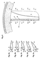
- FIGS. 5a-5e and 6 an embodiment of the invention is shown, which can be used particularly advantageous for the formation of an air turbine of an OWC wave power plant in addition to the present water turbines of a tidal power plant.
- the passive Blattwinkelverstellmechanismus is designed so that for the turbine blade 11 during operation in the radially outer region, a smaller Auswenkwinkel d arises from the plane of rotation compared to the radially inner regions.
- a possible embodiment is to provide a torsion-elastic profile 27, which has a stiffener 35 in the interior between the flown profile nose 33 and the hydrodynamic center 32, which defines a Torsionsachse. According to the terminology used in the present application, this is referred to below as the pivot axis 28.
- a generator rotor 19 is provided for the in FIG. 6 embodiment shown on the outer support ring 36. Further, the entire mounting of the rotating unit can be realized on a large outer radius, so that there is no need to provide a central element 5 according to the preceding embodiments
- FIGS. 7a-7c and 8 A further alternative design of a passive blade angle adjustment mechanism is shown, which allows a greater swinging in the radially inner region of the turbine blade.
- This is the in FIG. 8 Segmented turbine blade shown as a section through the plane of rotation.
- a three-part structure with a first segment 41, a second segment 42 and a third segment 43 is used.
- Each segment 41, 42, 43 can perform a rotational movement about a pivot pin 44 extending from the hub 13.
- a passage opening is provided in each segment 41, 42, 43, in each of which a bearing sleeve 46.1, 46.2, 46.3 is arranged from a sliding bearing material.
- spacers 41, 42, 43 are arranged between the individual segments.
- FIG. 9 shows an embodiment of an underwater power plant according to the invention with reference to a partial sectional view of a two-stage turbine arrangement.
- Radially outside the turbine blades 11.1, 11.2, 11.3, 12.1, 12.2, 12.3 of the respective stage are fixed in a torsionally rigid manner to a first outer ring 38 and a second outer ring 39.
- the profile of the respective turbine blade is aligned radially outward with the plane of rotation, while pivoting radially on the inside is possible.
- the first outer ring 38 runs in a first groove 48 in the outer housing and is supported by the bearing components 47.1, 47.2. Accordingly, a second groove 49 with the bearing components 47.3, 47.4 is provided for the second outer ring 39. Furthermore, the present embodiment can be transferred to the air turbine of a wave power plant.
- a speed or torque guidance of the turbine is effected by the directly coupled generator 40.
- a search algorithm based on an MPP controller is used for the manipulated variable specification, in this case the load torque at the electric generator 40.
- torsionally elastic turbine blades can be pivoted on an outer and an inner ring, which is set by differently set stops the maximum Aufschwenkwinkel radially inside larger than radially outside.
- the arrangement of the generator components and the associated storage can be done radially outside or radially inside.
- the distributor at least partially movable, so that there is a further possibility of adaptation to the direction and the speed of the flow.
Landscapes
- Engineering & Computer Science (AREA)
- Chemical & Material Sciences (AREA)
- Combustion & Propulsion (AREA)
- Mechanical Engineering (AREA)
- General Engineering & Computer Science (AREA)
- Life Sciences & Earth Sciences (AREA)
- General Life Sciences & Earth Sciences (AREA)
- Oceanography (AREA)
- Other Liquid Machine Or Engine Such As Wave Power Use (AREA)
- Hydraulic Turbines (AREA)
Description
Die Erfindung betrifft ein Unterwasserkraftwerk mit einer bidirektional anströmbaren, gleichsinnig umlaufenden Wasserturbine, insbesondere einer Wellsturbine, und einem Verfahren zu dessen Betrieb, wobei das Unterwasserkraftwerk vorzugsweise zur Ausnutzung einer Gezeitenströmung dient. Gegenstand einer Weiterführung der Erfindung ist eine bidirektionale Luftturbine.The invention relates to an underwater power plant with a bidirectionally flowable, in the same direction rotating water turbine, in particular a Wellsturbine, and a method for its operation, wherein the underwater power plant is preferably used to exploit a tidal current. Subject of a continuation of the invention is a bidirectional air turbine.
Freistehend in einer Umgebungsströmung platzierte Unterwasserkraftwerke stellen eine kostengünstige Variante für die Energiegewinnung aus einer Meeresströmung, insbesondere einer Gezeitenströmung, dar. Bekannt sind propellerförmig ausgestaltete Wasserturbinen, die an einer Maschinengondel umlaufen, welche im Inneren einen elektrischen Generator aufnimmt. Für eine alternative Gestaltung wird der elektrische Generator an der radial äußeren Peripherie der Wasserturbine angeordnet, das heißt die umlaufende Einheit der Wasserturbine umfasst einen Generatorläufer, der gegenüber den Turbinenblättern der Wasserturbine radial außen liegt und in einer ringförmigen Stützstruktur umläuft.Free-standing placed in an ambient flow underwater power plants represent a cost-effective variant for the energy from a sea current, in particular a tidal current, known. Are known propeller-shaped water turbines, which rotate on a nacelle, which receives an electric generator inside. For an alternative design, the electric generator is arranged on the radially outer periphery of the water turbine, that is to say the peripheral unit of the water turbine comprises a generator rotor which lies radially outward with respect to the turbine blades of the water turbine and circulates in an annular support structure.
Zur effizienten Ausnutzung einer bezüglich der Anströmungsrichtung zyklisch wechselnden Gezeitenströmung kann die Wasserturbine mit der Strömung nachgeführt werden, typischerweise wird die gesamte Gondel eines Unterwasserkraftwerks mit der Turbine-Generator-Einheit in die Strömung gedreht. Eine solche Ausgestaltung ist konstruktiv aufwändig und zieht nach sich, dass das vom elektrischen Generator ausgehende Verbindungskabel gegen eine Verdrillung zu schützen ist. Für einen alternativen Ansatz sind die Rotorblätter mit einem aktiven Blattwinkelverstellmechanismus ausgestattet, der eine Drehung des Blattprofils um 180° ermöglicht. Allerdings folgt hieraus ein hoher konstruktiver Aufwand zur Anlenkung der Blätter. Ferner besteht die Notwendigkeit, zur Steuerung des aktiven Blattwinkelverstellmechanismus externe Sensoren zu verwenden, die das Einsetzen einer Richtungsumkehr der Anströmung detektieren. Aus diesem Grund wurde vorgeschlagen, für eine robuste und einfache Gestaltung einer bidirektional anströmbaren Wasserturbine symmetrische Turbinenblätter einzusetzen. Dabei werden durch die
Die voranstehend angeführten symmetrischen Profile erlauben, eine sich umkehrende Strömungsrichtung auszunutzen, wobei eine Änderung der Anströmungsrichtung mit einem Wechsel der Umlaufrichtung der Wasserturbine verbunden ist. Als Alternative kann für eine zur Profilsehne symmetrische Gestaltung der Profile der Turbinenblätter mit einer Ausrichtung der Profilsehnen parallel zur Rotationsebene bei einem Richtungswechsel der Anströmung der Umlaufsinn beibehalten werden. Derartige Wellsturbinen sind aus der
Zur Verbesserung der Anströmungsverhältnisse an den Turbinenblättern sind stromaufwärts und stromabwärts der Wasserturbine Leitschaufeln vorgesehen, die zusätzlich zur Abstützung der zentralen Nabe verwendet werden, welche der Lagerung der Wasserturbine dient. Neben der konstruktiv aufwendigen Gestaltung für den Leitapparat besteht eine weitere Schwierigkeit darin, eine Anpassung an unterschiedliche Anströmungsgeschwindigkeiten oder eine Strömung mit schnellen Geschwindigkeitsfluktuationen vorzunehmen. Dabei besteht bei einer sich schnell verändernden Anströmungsgeschwindigkeit als Folge von Turbulenzen die Gefahr eines Strömungsabrisses an den Turbinenblättern, da eine Anpassung der Umlaufgeschwindigkeit der Wasserturbine vielfach nicht hinreichend schnell erfolgen kann. Eine weitere Schwierigkeit bei der Verwendung von Wellsturbinen, auch solchen, die mit einem Leitapparat ausgestattet sind, besteht darin, dass ein effizienter Betrieb eine hohe Umlaufdrehzahl voraussetzt, die zunächst den motorischen Betrieb des elektrischen Generators voraussetzt.To improve the flow conditions on the turbine blades guide vanes are provided upstream and downstream of the water turbine, which are used in addition to the support of the central hub, which serves to support the water turbine. In addition to the structurally complex design for the diffuser, another difficulty is to adapt to different flow velocities or to make a flow with rapid velocity fluctuations. In the case of a rapidly changing inflow velocity as a result of turbulence, there is the risk of a stall on the turbine blades, since an adaptation of the rotational speed of the water turbine can often not be carried out with sufficient speed. Another difficulty with the use of corrugated turbines, even those equipped with a diffuser, is that an efficient operation requires a high rotational speed, which initially requires the motor operation of the electric generator.
Zur Verbesserung von Wellsturbinen wird durch die
Der Erfindung liegt die Aufgabe zugrunde, ein Unterwasserkraftwerk mit einer bidirektional anströmbaren, gleichsinnig umlaufenden Wasserturbine so zu gestalten, dass die voranstehend dargelegten Probleme überwunden werden. Dabei sollte insbesondere ein Betrieb bei geringen Anströmungsgeschwindigkeiten oder hohen Geschwindigkeitsfluktuationen in der Anströmung möglich sein. Des Weiteren ist die Wasserturbine so auszubilden, dass der zugeordnete Leitapparat konstruktiv vereinfacht gestaltet oder gänzlich weggelassen werden kann. Gleichzeitig sollte die Wasserturbine auch bei kleinen Schnelllaufzahlen nicht zu einem Strömungsabriss neigen und bezüglich ihres Anlaufverhaltens verbessert sein. Ferner soll das Turbinendesign auf eine bidirektional anströmbare Luftturbine, insbesondere für ein OWC-Wellenkraftwerk übertragbar sein.The invention has for its object to make an underwater power plant with a bi-directionally flowable, co-rotating water turbine so that the above problems are overcome. In particular, an operation at low flow velocities or high velocity fluctuations in the flow should be possible. Furthermore, the water turbine is to be designed in such a way that the associated diffuser can be structurally simplified or omitted altogether. At the same time, the water turbine should not tend to stall even at low speeds and be improved in terms of their startup behavior. Furthermore, the turbine design should be transferable to a bidirectionally flowable air turbine, in particular for an OWC wave power plant.
Die der Erfindung zugrunde liegende Aufgabe wird durch die Merkmale des unabhängigen Anspruchs gelöst. Dabei haben die Erfinder erkannt, dass einer gattungsgemäßen Turbine eines Unterwasserkraftwerks ein passiver Blattwinkelverstellmechanismus mit einer Schwenkachse zuzuordnen ist, die auf der Profilsehne zwischen der anstromseitigen Profilnase und der Auffädellinie der hydrodynamischen Zentren liegt. Durch diese Maßnahme stellt sich in Abhängigkeit der an den Turbinenblättern angreifenden hydrodynamischen Kraft und der Fliehkraft ein bestimmter Winkel gegen die Rotationsebene ein. Entsprechend wird sich das Turbinenblatt bei großen hydrodynamischen Kräften und bei kleiner Schnelllaufzahl aus der Rotorebene heraus in Richtung der Fahnenstellung bewegen. Unter der Fahnenstellung wird verstanden, dass ein Winkel zwischen der Profilsehne und der Rotationsebene eintritt, der im Wesentlichen den Anstellwinkel des Profils gegen die effektive Anströmung zu Null führt.The object underlying the invention is solved by the features of the independent claim. The inventors have recognized that a generic turbine of an underwater power plant is assigned to a passive Blattwinkelverstellmechanismus with a pivot axis which lies on the chord between the upstream profile nose and the Aufpädellinie the hydrodynamic centers. As a result of this measure, depending on the hydrodynamic force acting on the turbine blades and the centrifugal force, a certain angle is set against the plane of rotation. Correspondingly, the turbine blade will move out of the rotor plane in the direction of the feathering position in the case of large hydrodynamic forces and with a small number of revolutions. Under the flag position is understood that an angle between the chord and the plane of rotation occurs, which essentially leads the angle of attack of the profile against the effective flow to zero.
Die Schwenkachse des passiven Blattwinkelverstellmechanismus kann konstruktiv entweder durch eine schwenkbare Anlenkung des Turbinenblatts an der umlaufenden Einheit der Wasserturbine definiert werden oder das Blatt wird torsionselastisch gestaltet, wobei die Aussteifungen des Turbinenblatts eine Torsionsachse festlegen, die gegenüber der Auffädellinie der hydrodynamischen Zentren stromaufwärts zur angeströmten Profilnase hin verlagert ist.The pivot axis of the passive blade angle adjustment mechanism may be constructively defined by either a pivotal articulation of the turbine blade on the rotating unit of the water turbine, or the blade will be torsionally resilient, with the stiffeners of the turbine blade defining a torsional axis that faces the upstream lobe profile upstream of the hydrodynamic center's threading line is relocated.
Für ein solchermaßen gestaltetes Turbinenblatt erzeugt die am hydrodynamischen Zentrum des jeweiligen Profilschnitts angreifende hydrodynamische Kraft ein aufschwenkendes Moment, das durch Fliehkräfte und elastische Rückstellkräfte ausbalanciert wird. Letztere können entweder im Turbinenblatt selbst erzeugt werden, dies ist insbesondere bei einem torsionselastisch ausgestalteten Turbinenblatt der Fall, oder im Fußpunkt eines schwenkbar an einer Stützstruktur angelenkten Turbinenblatts ist eine Vorrichtung vorgesehen, die gegen ein Aufschwenken des Blatts gerichtete, elastische Kräfte bewirkt. Im einfachsten Fall ist ein System aus rückstellenden Federn denkbar.For a turbine blade designed in this way, the hydrodynamic force acting on the hydrodynamic center of the respective profile section generates a swiveling moment caused by centrifugal forces and elastic restoring forces is balanced. The latter can either be generated in the turbine blade itself, this is the case in particular in a torsionally elastic designed turbine blade, or at the base of a turbine blade pivotally hinged to a support structure, a device is provided which causes against an upward pivoting of the blade, elastic forces. In the simplest case, a system of restoring springs is conceivable.
Durch den passiven Blattwinkelverstellmechanismus ist in Abhängigkeit der jeweils vorliegenden Schnelllaufzahl ein vorbestimmtes Aufschwenken des Turbinenblatts aus der Rotationsebene heraus möglich. Dies verringert die für den effizienten Betrieb notwendigen Umlaufgeschwindigkeiten der gattungsgemäßen Wasserturbine und führt bereits für den Normalbetrieb zu einer Steigerung des Wirkungsgrads. Zusätzlich schafft die Verkleinerung des stromaufwärtigen beziehungsweise stromabwärtigen Leitapparats eine weitere Effizienzsteigerung. Darüber hinaus erlaubt der passive Blattwinkelverstellmechanismus eine Erweiterung des Arbeitsbereichs, wobei für eine fluktuierende Anströmung ein Strömungsabriss hinausgezögert wird. Des Weiteren erlaubt die aufgeschwenkte Stellung der Turbinenblätter eine Vereinfachung des Anlaufens, so dass beim Anlagenstart der Übergang vom motorischen Antrieb mittels des elektrischen Generators zum Antrieb durch die hydrodynamischen Kräfte an der Wasserturbine früher erfolgen kann. Zusätzlich kann durch ein hinreichend weites Aufschwenken der Turbinenblätter in Richtung der Fahnenstellung eine Abregelung der Anlage beim Erreichen der Nennleistung bewirkt werden.Due to the passive blade angle adjustment mechanism, a predetermined pivoting of the turbine blade out of the plane of rotation is possible depending on the number of fast-running numbers present. This reduces the necessary for efficient operation circulation speeds of the generic water turbine and already leads for normal operation to an increase in efficiency. In addition, the downsizing of the upstream and downstream nozzles, respectively, provides a further increase in efficiency. In addition, the passive blade angle adjustment mechanism allows expansion of the working area, stalling for fluctuating flow. Furthermore, the pivoted position of the turbine blades allows a simplification of the start-up, so that the transition from the motor drive by means of the electric generator for driving through the hydrodynamic forces on the water turbine can be done earlier in the system start. In addition, by a sufficiently wide pivoting of the turbine blades in the direction of the feathering position, a reduction of the system when reaching the rated power can be effected.
Für eine Weitergestaltung der Erfindung wird zur Beeinflussung des Anstellwinkels der Turbinenblätter eine Geschwindigkeitsführung der Wasserturbine vorgesehen, die durch den elektrischen Generator bewirkt wird. Alternativ kann durch den elektrischen Generator ein Lastmoment vorgegeben werden. Besonders bevorzugt wird die Regelung beziehungsweise die Steuerung des Generators ohne eine störanfällige äußere Sensorik und ohne den Rückgriff auf Kennlinien ausgeführt. Stattdessen wir eine Suche des Maximums der vom elektrischen Generator abgegebenen Ausgangsleistung bewirkt. Besonders bevorzugt wird hierfür ein MPP-Regler (Maximum Power Point - MPP) verwendet. Dieser gibt eine Stellgröße für den direkt mit der Wasserturbine verbundenen elektrischen Generator mit einer zeitlichen Variation aus. Dies ist entweder die vom elektrischen Generator eingeprägte Umlaufgeschwindigkeit oder das an die Wasserturbine weitergegebene, vom elektrischen Generator bewirkte Lastmoment. Hierdurch resultiert eine Leistungsschwankung, durch die ein Leistungsgradient ermittelt werden kann, auf dessen Grundlage das Suchverfahren für die Leistungsmaximierung beruht. Dabei wird Insbesondere eine Drehzahlführung der Wasserturbine erwünscht, da hierdurch eine Anpassung der Schnelllaufzahl und damit eine Einflussnahme auf die mittels des passiven Blattwinkelverstellmechanismus bewirkte Stellung der Turbinenblätter möglich ist.For a further embodiment of the invention, a speed control of the water turbine is provided for influencing the angle of attack of the turbine blades, which is effected by the electric generator. Alternatively, a load torque can be specified by the electric generator. Particularly preferably, the control or the control of the generator is carried out without a fault-prone external sensor and without recourse to characteristics. Instead, we do a search of the maximum of the output power delivered by the electric generator. Particularly preferred For this a MPP controller (Maximum Power Point - MPP) is used. This gives a manipulated variable for the electric generator directly connected to the water turbine with a time variation. This is either the circulating speed impressed by the electric generator or the load torque transmitted to the water turbine and caused by the electric generator. This results in a power fluctuation, by which a power gradient can be determined on the basis of which the performance maximization search process is based. In particular, a speed control of the water turbine is desired because this allows an adaptation of the high-speed number and thus an influence on the effected by means of the passive Blattwinkelverstellmechanismus position of the turbine blades is possible.
Erfindungsgemäß ist vorgesehen, den Grad des Aufschwenkens in den radial äußeren Bereichen der Turbinenblätter gegenüber den radial inneren Bereichen zu verändern, insbesondere zu verringern. Aufgrund der radiusabhängigen Umfangsgeschwindigkeit ist der Winkel der effektiven Anströmung gegen die Rotationsebene größer an den radial inneren Bereichen des Turbinenblatts. Entsprechend ist in diesem Bereich ein stärkeres Aufschwenken im Vergleich zu den Turbinenblattspitzen notwendig. Für eine Ausgestaltungsvariante ist daher vorgesehen, die Turbinenblätter von einem äußeren Tragring ausgehend mit einer radial innen gerichteten Erstreckung auszubilden und zugleich die Turbinenblätter entweder mehrsegmentig oder torsionselastisch auszubilden. Die zugeordnete Schwenkachse liegt wiederum zwischen der angestrebten Profilnase und der Auffädellinie der hydrodynamischen Zentren.According to the invention, the degree of pivoting in the radially outer regions of the turbine blades relative to the radially inner regions to change, in particular to reduce. Due to the radius-dependent peripheral speed, the angle of the effective flow against the plane of rotation is greater at the radially inner regions of the turbine blade. Accordingly, in this area, a stronger pivoting compared to the turbine blade tips is necessary. For a design variant, it is therefore intended to form the turbine blades starting from an outer support ring with a radially inwardly directed extension and at the same time to form the turbine blades either in a multi-segment or torsionally-elastic manner. The associated pivot axis is in turn between the desired profile nose and the Aufpädellinie the hydrodynamic centers.
Im Falle einer torsionselastischen Ausgestaltung sind Aussteifungselemente im Profil vorgesehen, die die Torslonsachse festlegen. Entsprechend der in der Anmeldung verwendeten Terminologie entsteht damit eine definierte Schwenkachse. Für eine mehrsegmentige Ausgestaltung bilden die einzelnen Segmente radiale Abschnitte des Turbinenblatts, die jeweils gegeneinander um eine Schwenkachse drehbar sind, wobei die Möglichkeit besteht, den maximalen Schwenkwinkel zwischen zwei aufeinander folgenden Segmenten durch geeignet ausgeführte Anschlagselemente zu begrenzen.In the case of a torsionally elastic design stiffening elements are provided in the profile that define the Torslonsachse. According to the terminology used in the application thus creates a defined pivot axis. For a multi-segment design, the individual segments form radial sections of the turbine blade, which are each rotatable relative to each other about a pivot axis, with the possibility of the maximum To limit tilt angle between two successive segments by suitably designed stop elements.
Des Weiteren ist eine Ausgestaltung denkbar, für die die erfindungsgemäß gestalteten Turbinenblätter an einer radial äußeren Felge und einer radial inneren Nabe befestigt sind, wobei radial außen das Turbinenblatt im Vergleich zum radial inneren Teil nicht oder nur bis zu einem geringeren Schwenkwinkel ausschwenkbar ist. Eine Möglichkeit besteht in einer torsionselastischen Gestaltung des Turbinenblatts mit einer starren Befestigung des Turbinenblatts an der radial äußeren Felge, so dass die Profile dort bezüglich ihrer Profilsehnen in der Rotationsebene liegen. Wird ein solchermaßen gestaltetes Blatt radial innen an der Nabe schwenkbar angelenkt, entsteht eine stabile Führung und zugleich das gewünschte radiusabhängige Aufschwenken der Turbinenblätter.Furthermore, a configuration is conceivable for which the turbine blades designed according to the invention are fastened to a radially outer rim and a radially inner hub, wherein the turbine blade can not be swung radially outward compared to the radially inner part or only up to a smaller pivot angle. One possibility is a torsionally elastic design of the turbine blade with a rigid attachment of the turbine blade to the radially outer rim, so that the profiles are there with respect to their chords in the plane of rotation. If a blade designed in this way is pivoted radially inward on the hub, a stable guidance and at the same time the desired radius-dependent pivoting of the turbine blades results.
Für eine Weiterführung wird die Ausführung mit einem radiusabhängigen Schwenkwinkel auf eine Luftturbine übertragen, die insbesondere für die Verwendung in einem OWC-Wellenkraftwerk vorgesehen ist. Entsprechend umfasst die Luftturbine eine Vielzahl von Turbinenblättern, die über wenigstens einen Teil ihrer Längserstreckung ein tropfenförmiges Profil aufweisen, wobei die Luftturbine bei bidirektionaler Anströmung gleichsinnig umläuft. Erfindungsgemäß ist ein passiver Blattwinkelverstellmechanismus für die Turbinenblätter vorgesehen, wobei jedem Turbinenblatt eine Schwenkachse zugeordnet ist, die zwischen der angeströmten Profilnase und der Auffädellinie der aerodynamischen Zentren liegt, und wobei im Betrieb der Aufschwenkwinkel in den radial äußeren Bereichen des Turbinenblatts kleiner ist im Vergleich zu den radial inneren Bereichen.For a continuation, the embodiment is transmitted with a radius-dependent pivot angle to an air turbine, which is intended in particular for use in an OWC wave power plant. Accordingly, the air turbine comprises a plurality of turbine blades, which have a drop-shaped profile over at least part of their longitudinal extent, wherein the air turbine rotates in the same direction in bidirectional flow. According to the invention, a passive blade angle adjustment mechanism is provided for the turbine blades, wherein each turbine blade is associated with a pivot axis which lies between the impinged nose and the center line of the aerodynamic centers, and wherein in operation the Aufschwenkwinkel is smaller in the radially outer regions of the turbine blade in comparison to the radially inner areas.
Nachfolgend wird die Erfindung anhand von Ausführungsbeispielen in Verbindung mit Figurendarstellungen erläutert. In diesen ist im Einzelnen Folgendes dargestellt:
Figur 1- zeigt als axiale Teilschnittansicht ein Unterwasserkraftwerk mit einer zweistufig angelegten Wellsturbine, die einen passiven Blattwinkelverstellmechanismus umfasst.
Figur 2- zeigt einen vergrößerten Teilausschnitt aus
Figur 1 . Figur 3- zeigt einen Axialschnitt in der Rotationsebene für ein schwenkbar angelenktes Turbinenblatt.
Figur 4- zeigt den Schnitt
A-A aus Figur 3 - Figuren 5a - 5d
- zeigen Profilschnitte zur
Figur 6 . - Figur 6
- zeigt ein von einem äußeren Tragring nach radial innen gerichtete, torsionselastisch ausgebildete Turbinenblätter.
- Figuren 7a - 7c
- zeigen Profilschnitte aus
Figur 8 . - Figur 8
- zeigt ein segmentiert ausgebildetes Turbinenblatt, wobei die Einzelsegmente jeweils drehbar angelenkt sind.
- Figur 9
- zeigt ein Ausgestaltungsbeispiel einer zweistufigen Wasserturbine mit radial innen drehbar angelenkten Turbinenblättern, die radial außen mittels eines Außenrings drehstarr geführt sind.
- FIG. 1
- shows an axial partial sectional view of an underwater power plant with a two-stage Wellsturbine comprising a passive Blattwinkelverstellmechanismus.
- FIG. 2
- shows an enlarged partial section
FIG. 1 , - FIG. 3
- shows an axial section in the plane of rotation for a pivotally articulated turbine blade.
- FIG. 4
- shows the section AA
FIG. 3 - FIGS. 5a-5d
- show profile sections to
FIG. 6 , - FIG. 6
- shows a radially inwardly directed from an outer support ring, torsionally elastic trained turbine blades.
- FIGS. 7a-7c
- show profile sections
FIG. 8 , - FIG. 8
- shows a segmented trained turbine blade, the individual segments are each rotatably articulated.
- FIG. 9
- shows a design example of a two-stage water turbine with radially inwardly rotatably hinged turbine blades, which are guided radially outwardly by means of an outer ring torsionally rigid.
Die Innenwand 3 des äußeren Gehäuses 2 bildet einen Strömungskanal 4, wobei die Innenwand 3 bevorzugt als Konfusor/Diffusor-Kombination zur Strömungsbeschleunigung gestaltet ist, Innerhalb des Gehäuses 2 befindet sich ein Zentralelement 5, in dem die Lagerung der Wasserturbinen und der elektrische Generator 40 angeordnet sind. Dies wird nachfolgend im Detail im Zusammenhang mit
Ferner stellt
Der passive Blattwinkelverstellmechanismus wird nachfolgend anhand von
Aus der Teilschnittansicht des Zentralelements 5 ist ersichtlich, dass die Turbinenblätter der ersten Stufe 11.1, 11.2, 11.3 drehbar an einer ersten Nabe 16.1 befestigt sind. Hierzu ist für das Turbinenblatt der ersten Stufe 11.1 ein erster Achsstutzen 17.1 skizziert, der radial innen der hohl ausgebildeten ersten Nabe 16.1 mit einem Verriegelungselement 15 abschließt. Entsprechend ist das Turbinenblatt der zweiten Stufe 12.1 an einer zweiten Nabe 16.2 mittels des zweiten Achsstutzes 17.2 schwenkbar befestigt.From the partial sectional view of the
Die erste Nabe 16.1 und die zweite Nabe 16.2 sind über den Maschinenträger 18 verbunden und bilden eine gleichsinnig umlaufende Einheit. Dabei ist auf dem Maschinenträger 18 der Generatorläufer 19 des elektrischen Generators 40 angeordnet. Gegenüberliegend und durch den Luftspalt 20 beabstandet befindet sich der Generatorstator 21, der zur Verbesserung der thermischen Anbindung in Anlagekontakt zu einem mittleren Gehäuseteil 22 des Zentralelements 5 steht.The first hub 16.1 and the second hub 16.2 are connected via the
Für das dargestellte Ausführungsbeispiel umfasst das Zentralelement 5 eine erste Haube 23, die mittels der Leitschaufeln der ersten Stufe 7.1, 7.2 gegen das äußere Gehäuse 2 abgestützt sind. Spiegelsymmetrisch angelegt ist eine zweite Haube 24 vorgesehen, die durch die Leitschaufeln der zweiten Stufe 8.1, 8.2, 8.3 nach außen hin abgestützt ist. In der ersten Haube 23 ist ein erstes Axiallager 26.1 und in der zweiten Haube 24 ist ein zweites Axiallager 26.2 vorgesehen, die der axialen Abstützung der umlaufenden Einheit dienen. Für die radiale Lagerung sind an der ersten Haube 23, dem mittleren Gehäuseteil 22 und der zweiten Haube 24 das erste Radiallager 25.1, das zweite Radiallager 25.2, das dritte Radiallager 25.3 und das vierte Radiallager 25.4 angeordnet. Die genannten Lager können als Wälzlager mit Verlustschmierung ausgeführt sein, bevorzugt wird jedoch die Lagerung mittels wassergeschmierter Gleitlager realisiert, wobei für eine bevorzugte Ausführung auf Wellendichtungen verzichtet wird und Lagerbereich sowie der Luftspalt 20 des elektrischen Generators 40 geflutet sind. Hierzu sind die Komponenten des Generatorläufers 19 und des Generatorstators 21 durch eine Vergussmasse oder ein Spaltrohr wassergeschützt ausgeführt.For the illustrated embodiment, the
Aus dem Profilschnitt A-A in
In den
Des Weiteren ist für die in
In den
Dabei ist es möglich, die Relativbewegung der Distanzstücke 41, 42, 43 durch Anschlagsvorrichtungen zu begrenzen. Für die vorliegende Ausgestaltung wird hierauf verzichtet, so dass sich der Schwenkwinkel für jedes einzelne Segment 41, 42, 43 des Turbinenblatts unabhängig von den Nachbarsegmenten einstellt, wobei aufgrund der höheren Umfangsgeschwindigkeit die Fliehkraftwirkung auf die radial äußeren Segmente größer ist als auf die radial inneren, so dass diese im Vergleich zu den innenliegenden Segmenten kleinere Aufschwenkwinkel aufweisen.It is possible to limit the relative movement of the
Um für die aktuell vorliegende Strömung eine geeignete Turbinenumlaufgeschwindigkeit und damit einen bestimmten Aufschwenkwinkel d einstellen zu können, wird bevorzugt ein Drehzahl- oder Momentenführung der Turbine durch den direkt gekoppelten Generator 40 bewirkt. Dabei wird zur Stellgrößenfestlegung, vorliegend des Lastmoments am elektrischen Generator 40, ein Suchalgorithmus auf der Grundlage eines MPP-Reglers verwendet.In order to be able to set a suitable turbine rotational speed and thus a specific pivoting angle d for the currently present flow, preferably a speed or torque guidance of the turbine is effected by the directly coupled
Eine Weitergestaltung im Rahmen des fachmännischen Könnens ist möglich, dabei können insbesondere torsionselastische Turbinenblätter an einem Außenund einem Innenring drehbar angelenkt werden, wobei durch unterschiedlich eingestellte Anschläge der maximale Aufschwenkwinkel radial innen größer als radial außen ist. Des Weiteren können die Anordnung der Generatorkomponenten und die zugehörige Lagerung radial außen oder radial innen erfolgen. Ferner besteht die Möglichkeit, den Leitapparat wenigstens teilbeweglich auszubilden, so dass eine weitere Anpassungsmöglichkeit an die Richtung und die Geschwindigkeit der Anströmung besteht.A further design within the skill of the art is possible, in particular torsionally elastic turbine blades can be pivoted on an outer and an inner ring, which is set by differently set stops the maximum Aufschwenkwinkel radially inside larger than radially outside. Furthermore, the arrangement of the generator components and the associated storage can be done radially outside or radially inside. Furthermore, it is possible to form the distributor at least partially movable, so that there is a further possibility of adaptation to the direction and the speed of the flow.
- 11
- UnterwasserkraftwerkUnderwater power plant
- 22
- äußeres Gehäuseouter casing
- 33
- Innenwandinner wall
- 44
- Strömungskanalflow channel
- 55
- Zentralelementcentral element
- 6.16.1
- erste Turbinenstufefirst turbine stage
- 6.26.2
- zweite Turbinenstufesecond turbine stage
- 7.1, 7.27.1, 7.2
- Leitschaufel der ersten StufeGuide vane of the first stage
- 8.1, 8.2, 8.38.1, 8.2, 8.3
- Leitschaufel der zweiten StufeGuide vane of the second stage
- 9.1, 9.2, 9.39.1, 9.2, 9.3
- zentraler Leitapparatcentral distributor
- 1010
- Stützstruktursupport structure
- 1111
- Turbinenblattturbine blade
- 11.1, 11.2, 11.311.1, 11.2, 11.3
- Turbinenblatt der ersten StufeTurbine blade of the first stage
- 12.1, 12.2, 12.312.1, 12.2, 12.3
- Turbinenblatt der zweiten StufeTurbine blade of the second stage
- 1313
- Nabehub
- 1414
- Achsstutzenaxle stubs
- 1515
- Verriegelungselementlocking element
- 16.116.1
- erste Nabefirst hub
- 16.216.2
- zweite Nabesecond hub
- 17.117.1
- erster Achsstutzenfirst axle stub
- 17.217.2
- zweiter Achsstutzensecond axle socket
- 1818
- Maschinenträgermachine support
- 1919
- Generatorläufergenerator rotor
- 2020
- Luftspaltair gap
- 2121
- Generatorstatorgenerator stator
- 2222
- mittleres Gehäuseteilmiddle housing part
- 2323
- erste Haubefirst hood
- 2424
- zweite Haubesecond hood
- 25.125.1
- erstes Radiallagerfirst radial bearing
- 25.225.2
- zweites Radiallagersecond radial bearing
- 25.325.3
- drittes Radiallagerthird radial bearing
- 25.425.4
- viertes Radiallagerfourth radial bearing
- 26.126.1
- erstes Axiallagerfirst thrust bearing
- 26.226.2
- zweites Axiallagersecond thrust bearing
- 2727
- Profilprofile
- 2828
- Schwenkachseswivel axis
- 2929
- Lagerhülsebearing sleeve
- 3030
- Rotationsachseaxis of rotation
- 3131
- Auffädellinie der hydrodynamischen ZentrenThreading line of hydrodynamic centers
- 3232
- hydrodynamisches Zentrumhydrodynamic center
- 3333
- angeströmte Profilnasestreamlined profile nose
- 3434
- Profilsehnechord
- 3535
- Aussteifungstiffening
- 3636
- äußerer Tragringouter support ring
- 3737
- Achsstutzenaxle stubs
- 3838
- erster Außenringfirst outer ring
- 3939
- zweiter Außenringsecond outer ring
- 4040
- elektrischer Generatorelectric generator
- 4141
- erstes Segmentfirst segment
- 4242
- zweites Segmentsecond segment
- 4343
- drittes Segmentthird segment
- 4444
- viertes Segmentfourth segment
- 45.1,45.2 45.3, 45.445.1,45.2 45.3, 45.4
- Distanzstückspacer
- 46.1, 46.2, 46.346.1, 46.2, 46.3
- Lagerhülsebearing sleeve
- 47.1, 47.2 47.3, 47.447.1, 47.2 47.3, 47.4
- Lagerkomponentebearing component
- 4848
- erste Nutfirst groove
- 4949
- zweite Nutsecond groove
- cc
- Anströmungsgeschwindigkeitinflow velocity
- dd
- AufschwenkwinkelAufschwenkwinkel
- uu
- negative Umfangsgeschwindigkeitnegative peripheral speed
- ww
- effektive Anströmungeffective flow
- Fl F l
- Auftriebskraftbuoyancy
- Fd F d
- Bremskraftbraking force
- Fr F r
- resultierende Kraftresulting power
- Ft F t
- tangentiale Kraftkomponentetangential force component
- Fy F y
- Querkraftlateral force
Claims (7)
- An underwater power plant comprising1.1 an electric generator (40);1.2 a water turbine with bidirectional fluid flow and unidirectional rotation with a plurality of turbine blades (11), having a teardrop-shaped profile over at least a portion of their longitudinal extension; and whereas the water turbine includes a passive mechanism to control the pitch angle of the blades of the turbine (11),1.3 characterised in that the mechanism to control the pitch angle of the blades1.4 causes a small radius related swivel-open angle (d), whereas the swivel-open angle (d) in the radially external regions of the turbine blade is smaller compared to the radially internal regions,
and whereas each turbine blade (11) is associated a swivel axis (28), which is situated between the inflow profile nose (33) and the threading line of the hydrodynamic centres (31). - An underwater power plant according to claim 1, characterised in that least a portion of the turbine blades is divided into individual segments (41, 42, 43, 44) extending radially.
- An underwater power plant according to one of claims 1 or 2, characterised in that the turbine blades are torsion elastic and are directed radially and inwardly from an external supporting ring (36).
- An underwater power plant according to one of claims 1 to 3, characterised in that the turbine blades are secured in a torsionally rigid manner to an outer ring (38, 39) and are hinged in a swivel fashion to a hub (30) lying radially and inwardly with respect thereto.
- An air turbine with a plurality of turbine blades (11), having a teardrop-shaped profile over at least a portion of their longitudinal extension, whereas the air turbine rotates in the same direction in the presence of a bidirectional inflow; and whereas the air turbine includes a passive mechanism to control the pitch angle of the blades of the turbine (11), and whereas each turbine blade (11) is associated a swivel axis (28), which is situated between the inflow profile nose (33) and the threading line of the hydrodynamic centres (31); characterised in that during operation, the swivel-open angle (d) in the radially external regions of the turbine blade is smaller compared to the radially internal regions.
- An air turbine according to claim 5, characterised in that the turbine blades are torsion elastic and are directed radially and inwardly from an external supporting ring (36) or are secured in a torsionally rigid manner to an outer ring (38, 39) and are hinged in a swivel fashion to a hub (30) lying radially and inwardly with respect thereto.
- An air turbine according to one of claims 5 or 6, characterised in that least a portion of the turbine blades is divided into individual segments (41, 42, 43, 44) extending radially.
Applications Claiming Priority (2)
| Application Number | Priority Date | Filing Date | Title |
|---|---|---|---|
| DE102009018758A DE102009018758A1 (en) | 2009-04-27 | 2009-04-27 | Underwater power plant with a bi-directional, co-rotating water turbine |
| PCT/EP2010/002059 WO2010124778A2 (en) | 2009-04-27 | 2010-03-31 | Underwater power plant comprising a water turbine with bidirectional fluid flow and unidirectional rotation |
Publications (2)
| Publication Number | Publication Date |
|---|---|
| EP2425124A2 EP2425124A2 (en) | 2012-03-07 |
| EP2425124B1 true EP2425124B1 (en) | 2013-03-27 |
Family
ID=42779713
Family Applications (1)
| Application Number | Title | Priority Date | Filing Date |
|---|---|---|---|
| EP10718061A Not-in-force EP2425124B1 (en) | 2009-04-27 | 2010-03-31 | Underwater power plant comprising a water turbine with bidirectional fluid flow and unidirectional rotation |
Country Status (5)
| Country | Link |
|---|---|
| EP (1) | EP2425124B1 (en) |
| DE (1) | DE102009018758A1 (en) |
| ES (1) | ES2403232T3 (en) |
| PT (1) | PT2425124E (en) |
| WO (1) | WO2010124778A2 (en) |
Cited By (1)
| Publication number | Priority date | Publication date | Assignee | Title |
|---|---|---|---|---|
| WO2024085773A2 (en) | 2022-10-20 | 2024-04-25 | Felicianne As | Bi-directional wave energy converter |
Families Citing this family (4)
| Publication number | Priority date | Publication date | Assignee | Title |
|---|---|---|---|---|
| US8702396B2 (en) * | 2010-07-09 | 2014-04-22 | Inha-Industry Partnership Institute | Separative tidal current rotor blade |
| CN103147904B (en) * | 2013-02-21 | 2015-06-24 | 哈尔滨电机厂有限责任公司 | Double-oblique-arm rotating mechanism used for tidal current power generation |
| DE202017102221U1 (en) * | 2017-04-12 | 2018-07-13 | Rolf Rohden | Turbine and tidal power plant |
| CN113202686B (en) * | 2021-03-21 | 2023-12-26 | 济南荣庆节能技术有限公司 | Device for generating electricity by using tidal energy |
Family Cites Families (11)
| Publication number | Priority date | Publication date | Assignee | Title |
|---|---|---|---|---|
| CH316900A (en) | 1953-04-15 | 1956-10-31 | Escher Wyss Ag | Hydroelectric machine system with counter-rotating impellers |
| GB1574379A (en) | 1977-08-24 | 1980-09-03 | English Electric Co Ltd | Turbines and like rotary machines |
| GB2140810B (en) | 1983-05-24 | 1987-07-08 | Celltech Ltd | Polypeptide and protein products, and process for their production |
| JPS6098103A (en) * | 1983-11-02 | 1985-06-01 | Tohoku Electric Power Co Inc | Air turbine unit with roter blade |
| JPS63219801A (en) * | 1987-03-06 | 1988-09-13 | Saga Univ | Turbine for wave activated power generation with self-adjustable pitch blade |
| US6116856A (en) | 1998-09-18 | 2000-09-12 | Patterson Technique, Inc. | Bi-directional fan having asymmetric, reversible blades |
| WO2003025385A2 (en) | 2001-09-17 | 2003-03-27 | Clean Current Power Systems Inc. | Underwater ducted turbine |
| GB2392713B (en) * | 2003-09-13 | 2004-10-13 | John Hunter | Multi-direction flow power turbine |
| US20050271508A1 (en) | 2004-06-03 | 2005-12-08 | Asfaw Beyene | Flexible turbine blade |
| NL2000840C2 (en) * | 2007-08-31 | 2009-03-03 | Tocardo B V | Device for converting kinetic energy of a flowing water into kinetic energy of a rotatable rotor shaft. |
| DE102008051370A1 (en) * | 2008-10-15 | 2010-04-22 | Voith Patent Gmbh | Underwater power plant with passive power control |
-
2009
- 2009-04-27 DE DE102009018758A patent/DE102009018758A1/en not_active Withdrawn
-
2010
- 2010-03-31 PT PT107180614T patent/PT2425124E/en unknown
- 2010-03-31 ES ES10718061T patent/ES2403232T3/en active Active
- 2010-03-31 EP EP10718061A patent/EP2425124B1/en not_active Not-in-force
- 2010-03-31 WO PCT/EP2010/002059 patent/WO2010124778A2/en not_active Ceased
Cited By (1)
| Publication number | Priority date | Publication date | Assignee | Title |
|---|---|---|---|---|
| WO2024085773A2 (en) | 2022-10-20 | 2024-04-25 | Felicianne As | Bi-directional wave energy converter |
Also Published As
| Publication number | Publication date |
|---|---|
| WO2010124778A3 (en) | 2011-06-30 |
| PT2425124E (en) | 2013-04-19 |
| ES2403232T3 (en) | 2013-05-16 |
| EP2425124A2 (en) | 2012-03-07 |
| DE102009018758A1 (en) | 2010-10-28 |
| WO2010124778A2 (en) | 2010-11-04 |
Similar Documents
| Publication | Publication Date | Title |
|---|---|---|
| DE69404179T2 (en) | Wind turbine | |
| EP1255931B1 (en) | Wind power installation with two rotors in tandem | |
| EP1440240B1 (en) | Generator for a hydro-electric station | |
| EP2235365B1 (en) | Wind power plant | |
| EP1002949A2 (en) | Vertical axis wind turbine | |
| DE102010011708A1 (en) | Turbine with passive blade adjustment | |
| DE102009025857A1 (en) | Wind turbine rotor blade floor plans with twisted and tapered tips | |
| EP2425124B1 (en) | Underwater power plant comprising a water turbine with bidirectional fluid flow and unidirectional rotation | |
| EP2729695B1 (en) | Run-of-the-river or marine current power plant and method for operating the same | |
| WO2023001864A1 (en) | Flow power plant having pivoting blades | |
| DE102008051370A1 (en) | Underwater power plant with passive power control | |
| EP1387954B1 (en) | Wind turbine comprising a vertical axis | |
| EP2522847B1 (en) | Flow power plant park and method for its production | |
| DE102009051117B4 (en) | Horizontal runner turbine with passive yaw angle adjuster | |
| EP3878732B1 (en) | Method and device for adjusting the voltage of a propeller | |
| EP4189235B1 (en) | Universal propeller, operating method and favoured uses | |
| WO2009089902A2 (en) | Air turbine for a wave power station | |
| EP2920454B1 (en) | Device for utilisation of kinetic energy of a flowing medium | |
| DE2930073A1 (en) | Wind driven power generator - has rotor within casing profiled to increase air velocity to utilise low wind speeds | |
| EP2521856B1 (en) | Tidal power plant and method for operating said tidal power plant | |
| EP2636892A2 (en) | Wind power plant and method for generating of rotary energy from wind | |
| WO2011100953A2 (en) | Turbine power plant | |
| DE202008010290U1 (en) | Wind power according to the Darrieus principle | |
| DE3590007T1 (en) | Wind rotor | |
| DE10251388A1 (en) | Rotor for a wind-power installation has a main body rotating on bearings around an axis of rotation driven by wind power with drive surfaces set with a clearance |
Legal Events
| Date | Code | Title | Description |
|---|---|---|---|
| PUAI | Public reference made under article 153(3) epc to a published international application that has entered the european phase |
Free format text: ORIGINAL CODE: 0009012 |
|
| 17P | Request for examination filed |
Effective date: 20110913 |
|
| AK | Designated contracting states |
Kind code of ref document: A2 Designated state(s): AT BE BG CH CY CZ DE DK EE ES FI FR GB GR HR HU IE IS IT LI LT LU LV MC MK MT NL NO PL PT RO SE SI SK SM TR |
|
| DAX | Request for extension of the european patent (deleted) | ||
| GRAP | Despatch of communication of intention to grant a patent |
Free format text: ORIGINAL CODE: EPIDOSNIGR1 |
|
| RIC1 | Information provided on ipc code assigned before grant |
Ipc: F03B 17/06 20060101AFI20121205BHEP Ipc: F03B 13/26 20060101ALI20121205BHEP |
|
| GRAS | Grant fee paid |
Free format text: ORIGINAL CODE: EPIDOSNIGR3 |
|
| GRAA | (expected) grant |
Free format text: ORIGINAL CODE: 0009210 |
|
| AK | Designated contracting states |
Kind code of ref document: B1 Designated state(s): AT BE BG CH CY CZ DE DK EE ES FI FR GB GR HR HU IE IS IT LI LT LU LV MC MK MT NL NO PL PT RO SE SI SK SM TR |
|
| REG | Reference to a national code |
Ref country code: GB Ref legal event code: FG4D Free format text: NOT ENGLISH |
|
| REG | Reference to a national code |
Ref country code: CH Ref legal event code: EP |
|
| REG | Reference to a national code |
Ref country code: AT Ref legal event code: REF Ref document number: 603567 Country of ref document: AT Kind code of ref document: T Effective date: 20130415 |
|
| REG | Reference to a national code |
Ref country code: PT Ref legal event code: SC4A Free format text: AVAILABILITY OF NATIONAL TRANSLATION Effective date: 20130415 |
|
| REG | Reference to a national code |
Ref country code: IE Ref legal event code: FG4D Free format text: LANGUAGE OF EP DOCUMENT: GERMAN |
|
| REG | Reference to a national code |
Ref country code: ES Ref legal event code: FG2A Ref document number: 2403232 Country of ref document: ES Kind code of ref document: T3 Effective date: 20130516 |
|
| REG | Reference to a national code |
Ref country code: DE Ref legal event code: R096 Ref document number: 502010002720 Country of ref document: DE Effective date: 20130529 |
|
| REG | Reference to a national code |
Ref country code: NO Ref legal event code: T2 Effective date: 20130327 |
|
| PG25 | Lapsed in a contracting state [announced via postgrant information from national office to epo] |
Ref country code: LT Free format text: LAPSE BECAUSE OF FAILURE TO SUBMIT A TRANSLATION OF THE DESCRIPTION OR TO PAY THE FEE WITHIN THE PRESCRIBED TIME-LIMIT Effective date: 20130327 Ref country code: BG Free format text: LAPSE BECAUSE OF FAILURE TO SUBMIT A TRANSLATION OF THE DESCRIPTION OR TO PAY THE FEE WITHIN THE PRESCRIBED TIME-LIMIT Effective date: 20130627 Ref country code: SE Free format text: LAPSE BECAUSE OF FAILURE TO SUBMIT A TRANSLATION OF THE DESCRIPTION OR TO PAY THE FEE WITHIN THE PRESCRIBED TIME-LIMIT Effective date: 20130327 |
|
| REG | Reference to a national code |
Ref country code: LT Ref legal event code: MG4D |
|
| PG25 | Lapsed in a contracting state [announced via postgrant information from national office to epo] |
Ref country code: LV Free format text: LAPSE BECAUSE OF FAILURE TO SUBMIT A TRANSLATION OF THE DESCRIPTION OR TO PAY THE FEE WITHIN THE PRESCRIBED TIME-LIMIT Effective date: 20130327 Ref country code: GR Free format text: LAPSE BECAUSE OF FAILURE TO SUBMIT A TRANSLATION OF THE DESCRIPTION OR TO PAY THE FEE WITHIN THE PRESCRIBED TIME-LIMIT Effective date: 20130628 Ref country code: FI Free format text: LAPSE BECAUSE OF FAILURE TO SUBMIT A TRANSLATION OF THE DESCRIPTION OR TO PAY THE FEE WITHIN THE PRESCRIBED TIME-LIMIT Effective date: 20130327 Ref country code: SI Free format text: LAPSE BECAUSE OF FAILURE TO SUBMIT A TRANSLATION OF THE DESCRIPTION OR TO PAY THE FEE WITHIN THE PRESCRIBED TIME-LIMIT Effective date: 20130327 |
|
| REG | Reference to a national code |
Ref country code: NL Ref legal event code: VDEP Effective date: 20130327 |
|
| BERE | Be: lapsed |
Owner name: VOITH PATENT G.M.B.H. Effective date: 20130331 |
|
| PG25 | Lapsed in a contracting state [announced via postgrant information from national office to epo] |
Ref country code: HR Free format text: LAPSE BECAUSE OF FAILURE TO SUBMIT A TRANSLATION OF THE DESCRIPTION OR TO PAY THE FEE WITHIN THE PRESCRIBED TIME-LIMIT Effective date: 20130327 |
|
| PG25 | Lapsed in a contracting state [announced via postgrant information from national office to epo] |
Ref country code: RO Free format text: LAPSE BECAUSE OF FAILURE TO SUBMIT A TRANSLATION OF THE DESCRIPTION OR TO PAY THE FEE WITHIN THE PRESCRIBED TIME-LIMIT Effective date: 20130327 Ref country code: SK Free format text: LAPSE BECAUSE OF FAILURE TO SUBMIT A TRANSLATION OF THE DESCRIPTION OR TO PAY THE FEE WITHIN THE PRESCRIBED TIME-LIMIT Effective date: 20130327 Ref country code: EE Free format text: LAPSE BECAUSE OF FAILURE TO SUBMIT A TRANSLATION OF THE DESCRIPTION OR TO PAY THE FEE WITHIN THE PRESCRIBED TIME-LIMIT Effective date: 20130327 Ref country code: NL Free format text: LAPSE BECAUSE OF FAILURE TO SUBMIT A TRANSLATION OF THE DESCRIPTION OR TO PAY THE FEE WITHIN THE PRESCRIBED TIME-LIMIT Effective date: 20130327 Ref country code: MC Free format text: LAPSE BECAUSE OF NON-PAYMENT OF DUE FEES Effective date: 20130331 Ref country code: IS Free format text: LAPSE BECAUSE OF FAILURE TO SUBMIT A TRANSLATION OF THE DESCRIPTION OR TO PAY THE FEE WITHIN THE PRESCRIBED TIME-LIMIT Effective date: 20130727 Ref country code: CZ Free format text: LAPSE BECAUSE OF FAILURE TO SUBMIT A TRANSLATION OF THE DESCRIPTION OR TO PAY THE FEE WITHIN THE PRESCRIBED TIME-LIMIT Effective date: 20130327 |
|
| PG25 | Lapsed in a contracting state [announced via postgrant information from national office to epo] |
Ref country code: PL Free format text: LAPSE BECAUSE OF FAILURE TO SUBMIT A TRANSLATION OF THE DESCRIPTION OR TO PAY THE FEE WITHIN THE PRESCRIBED TIME-LIMIT Effective date: 20130327 Ref country code: CY Free format text: LAPSE BECAUSE OF FAILURE TO SUBMIT A TRANSLATION OF THE DESCRIPTION OR TO PAY THE FEE WITHIN THE PRESCRIBED TIME-LIMIT Effective date: 20130327 |
|
| REG | Reference to a national code |
Ref country code: IE Ref legal event code: MM4A |
|
| PG25 | Lapsed in a contracting state [announced via postgrant information from national office to epo] |
Ref country code: DK Free format text: LAPSE BECAUSE OF FAILURE TO SUBMIT A TRANSLATION OF THE DESCRIPTION OR TO PAY THE FEE WITHIN THE PRESCRIBED TIME-LIMIT Effective date: 20130327 Ref country code: BE Free format text: LAPSE BECAUSE OF NON-PAYMENT OF DUE FEES Effective date: 20130331 Ref country code: IE Free format text: LAPSE BECAUSE OF NON-PAYMENT OF DUE FEES Effective date: 20130331 |
|
| PLBE | No opposition filed within time limit |
Free format text: ORIGINAL CODE: 0009261 |
|
| STAA | Information on the status of an ep patent application or granted ep patent |
Free format text: STATUS: NO OPPOSITION FILED WITHIN TIME LIMIT |
|
| PG25 | Lapsed in a contracting state [announced via postgrant information from national office to epo] |
Ref country code: IT Free format text: LAPSE BECAUSE OF FAILURE TO SUBMIT A TRANSLATION OF THE DESCRIPTION OR TO PAY THE FEE WITHIN THE PRESCRIBED TIME-LIMIT Effective date: 20130327 |
|
| 26N | No opposition filed |
Effective date: 20140103 |
|
| REG | Reference to a national code |
Ref country code: DE Ref legal event code: R097 Ref document number: 502010002720 Country of ref document: DE Effective date: 20140103 |
|
| PG25 | Lapsed in a contracting state [announced via postgrant information from national office to epo] |
Ref country code: MT Free format text: LAPSE BECAUSE OF FAILURE TO SUBMIT A TRANSLATION OF THE DESCRIPTION OR TO PAY THE FEE WITHIN THE PRESCRIBED TIME-LIMIT Effective date: 20130327 |
|
| REG | Reference to a national code |
Ref country code: CH Ref legal event code: PL |
|
| PG25 | Lapsed in a contracting state [announced via postgrant information from national office to epo] |
Ref country code: LI Free format text: LAPSE BECAUSE OF NON-PAYMENT OF DUE FEES Effective date: 20140331 Ref country code: CH Free format text: LAPSE BECAUSE OF NON-PAYMENT OF DUE FEES Effective date: 20140331 |
|
| REG | Reference to a national code |
Ref country code: FR Ref legal event code: PLFP Year of fee payment: 6 |
|
| PGFP | Annual fee paid to national office [announced via postgrant information from national office to epo] |
Ref country code: NO Payment date: 20150312 Year of fee payment: 6 Ref country code: PT Payment date: 20150330 Year of fee payment: 6 Ref country code: DE Payment date: 20150320 Year of fee payment: 6 Ref country code: ES Payment date: 20150326 Year of fee payment: 6 |
|
| PG25 | Lapsed in a contracting state [announced via postgrant information from national office to epo] |
Ref country code: SM Free format text: LAPSE BECAUSE OF FAILURE TO SUBMIT A TRANSLATION OF THE DESCRIPTION OR TO PAY THE FEE WITHIN THE PRESCRIBED TIME-LIMIT Effective date: 20130327 |
|
| PGFP | Annual fee paid to national office [announced via postgrant information from national office to epo] |
Ref country code: FR Payment date: 20150319 Year of fee payment: 6 Ref country code: GB Payment date: 20150319 Year of fee payment: 6 |
|
| PG25 | Lapsed in a contracting state [announced via postgrant information from national office to epo] |
Ref country code: TR Free format text: LAPSE BECAUSE OF FAILURE TO SUBMIT A TRANSLATION OF THE DESCRIPTION OR TO PAY THE FEE WITHIN THE PRESCRIBED TIME-LIMIT Effective date: 20130327 |
|
| PG25 | Lapsed in a contracting state [announced via postgrant information from national office to epo] |
Ref country code: MK Free format text: LAPSE BECAUSE OF FAILURE TO SUBMIT A TRANSLATION OF THE DESCRIPTION OR TO PAY THE FEE WITHIN THE PRESCRIBED TIME-LIMIT Effective date: 20130327 Ref country code: LU Free format text: LAPSE BECAUSE OF NON-PAYMENT OF DUE FEES Effective date: 20130331 Ref country code: HU Free format text: LAPSE BECAUSE OF FAILURE TO SUBMIT A TRANSLATION OF THE DESCRIPTION OR TO PAY THE FEE WITHIN THE PRESCRIBED TIME-LIMIT; INVALID AB INITIO Effective date: 20100331 |
|
| REG | Reference to a national code |
Ref country code: AT Ref legal event code: MM01 Ref document number: 603567 Country of ref document: AT Kind code of ref document: T Effective date: 20150331 |
|
| PG25 | Lapsed in a contracting state [announced via postgrant information from national office to epo] |
Ref country code: AT Free format text: LAPSE BECAUSE OF NON-PAYMENT OF DUE FEES Effective date: 20150331 |
|
| REG | Reference to a national code |
Ref country code: DE Ref legal event code: R119 Ref document number: 502010002720 Country of ref document: DE |
|
| REG | Reference to a national code |
Ref country code: NO Ref legal event code: MMEP |
|
| GBPC | Gb: european patent ceased through non-payment of renewal fee |
Effective date: 20160331 |
|
| PG25 | Lapsed in a contracting state [announced via postgrant information from national office to epo] |
Ref country code: PT Free format text: LAPSE BECAUSE OF NON-PAYMENT OF DUE FEES Effective date: 20160930 |
|
| REG | Reference to a national code |
Ref country code: FR Ref legal event code: ST Effective date: 20161130 |
|
| PG25 | Lapsed in a contracting state [announced via postgrant information from national office to epo] |
Ref country code: GB Free format text: LAPSE BECAUSE OF NON-PAYMENT OF DUE FEES Effective date: 20160331 Ref country code: DE Free format text: LAPSE BECAUSE OF NON-PAYMENT OF DUE FEES Effective date: 20161001 Ref country code: NO Free format text: LAPSE BECAUSE OF NON-PAYMENT OF DUE FEES Effective date: 20160331 Ref country code: FR Free format text: LAPSE BECAUSE OF NON-PAYMENT OF DUE FEES Effective date: 20160331 |
|
| REG | Reference to a national code |
Ref country code: ES Ref legal event code: FD2A Effective date: 20170428 |
|
| PG25 | Lapsed in a contracting state [announced via postgrant information from national office to epo] |
Ref country code: ES Free format text: LAPSE BECAUSE OF NON-PAYMENT OF DUE FEES Effective date: 20160401 |