EP2425124B1 - Centrale électrique immergée équipée d'une turbine hydraulique tournant dans le même sens et à écoulement bidirectionnel - Google Patents
Centrale électrique immergée équipée d'une turbine hydraulique tournant dans le même sens et à écoulement bidirectionnel Download PDFInfo
- Publication number
- EP2425124B1 EP2425124B1 EP10718061A EP10718061A EP2425124B1 EP 2425124 B1 EP2425124 B1 EP 2425124B1 EP 10718061 A EP10718061 A EP 10718061A EP 10718061 A EP10718061 A EP 10718061A EP 2425124 B1 EP2425124 B1 EP 2425124B1
- Authority
- EP
- European Patent Office
- Prior art keywords
- turbine
- radially
- blades
- power plant
- swivel
- Prior art date
- Legal status (The legal status is an assumption and is not a legal conclusion. Google has not performed a legal analysis and makes no representation as to the accuracy of the status listed.)
- Not-in-force
Links
Images


Classifications
-
- F—MECHANICAL ENGINEERING; LIGHTING; HEATING; WEAPONS; BLASTING
- F03—MACHINES OR ENGINES FOR LIQUIDS; WIND, SPRING, OR WEIGHT MOTORS; PRODUCING MECHANICAL POWER OR A REACTIVE PROPULSIVE THRUST, NOT OTHERWISE PROVIDED FOR
- F03B—MACHINES OR ENGINES FOR LIQUIDS
- F03B13/00—Adaptations of machines or engines for special use; Combinations of machines or engines with driving or driven apparatus; Power stations or aggregates
- F03B13/12—Adaptations of machines or engines for special use; Combinations of machines or engines with driving or driven apparatus; Power stations or aggregates characterised by using wave or tide energy
- F03B13/26—Adaptations of machines or engines for special use; Combinations of machines or engines with driving or driven apparatus; Power stations or aggregates characterised by using wave or tide energy using tide energy
- F03B13/264—Adaptations of machines or engines for special use; Combinations of machines or engines with driving or driven apparatus; Power stations or aggregates characterised by using wave or tide energy using tide energy using the horizontal flow of water resulting from tide movement
-
- F—MECHANICAL ENGINEERING; LIGHTING; HEATING; WEAPONS; BLASTING
- F03—MACHINES OR ENGINES FOR LIQUIDS; WIND, SPRING, OR WEIGHT MOTORS; PRODUCING MECHANICAL POWER OR A REACTIVE PROPULSIVE THRUST, NOT OTHERWISE PROVIDED FOR
- F03B—MACHINES OR ENGINES FOR LIQUIDS
- F03B13/00—Adaptations of machines or engines for special use; Combinations of machines or engines with driving or driven apparatus; Power stations or aggregates
- F03B13/12—Adaptations of machines or engines for special use; Combinations of machines or engines with driving or driven apparatus; Power stations or aggregates characterised by using wave or tide energy
- F03B13/14—Adaptations of machines or engines for special use; Combinations of machines or engines with driving or driven apparatus; Power stations or aggregates characterised by using wave or tide energy using wave energy
- F03B13/24—Adaptations of machines or engines for special use; Combinations of machines or engines with driving or driven apparatus; Power stations or aggregates characterised by using wave or tide energy using wave energy to produce a flow of air, e.g. to drive an air turbine
-
- F—MECHANICAL ENGINEERING; LIGHTING; HEATING; WEAPONS; BLASTING
- F03—MACHINES OR ENGINES FOR LIQUIDS; WIND, SPRING, OR WEIGHT MOTORS; PRODUCING MECHANICAL POWER OR A REACTIVE PROPULSIVE THRUST, NOT OTHERWISE PROVIDED FOR
- F03B—MACHINES OR ENGINES FOR LIQUIDS
- F03B3/00—Machines or engines of reaction type; Parts or details peculiar thereto
- F03B3/12—Blades; Blade-carrying rotors
- F03B3/14—Rotors having adjustable blades
- F03B3/145—Mechanisms for adjusting the blades
-
- F—MECHANICAL ENGINEERING; LIGHTING; HEATING; WEAPONS; BLASTING
- F05—INDEXING SCHEMES RELATING TO ENGINES OR PUMPS IN VARIOUS SUBCLASSES OF CLASSES F01-F04
- F05B—INDEXING SCHEME RELATING TO WIND, SPRING, WEIGHT, INERTIA OR LIKE MOTORS, TO MACHINES OR ENGINES FOR LIQUIDS COVERED BY SUBCLASSES F03B, F03D AND F03G
- F05B2210/00—Working fluid
- F05B2210/40—Flow geometry or direction
- F05B2210/404—Flow geometry or direction bidirectional, i.e. in opposite, alternating directions
-
- F—MECHANICAL ENGINEERING; LIGHTING; HEATING; WEAPONS; BLASTING
- F05—INDEXING SCHEMES RELATING TO ENGINES OR PUMPS IN VARIOUS SUBCLASSES OF CLASSES F01-F04
- F05B—INDEXING SCHEME RELATING TO WIND, SPRING, WEIGHT, INERTIA OR LIKE MOTORS, TO MACHINES OR ENGINES FOR LIQUIDS COVERED BY SUBCLASSES F03B, F03D AND F03G
- F05B2240/00—Components
- F05B2240/20—Rotors
- F05B2240/30—Characteristics of rotor blades, i.e. of any element transforming dynamic fluid energy to or from rotational energy and being attached to a rotor
- F05B2240/31—Characteristics of rotor blades, i.e. of any element transforming dynamic fluid energy to or from rotational energy and being attached to a rotor of changeable form or shape
-
- F—MECHANICAL ENGINEERING; LIGHTING; HEATING; WEAPONS; BLASTING
- F05—INDEXING SCHEMES RELATING TO ENGINES OR PUMPS IN VARIOUS SUBCLASSES OF CLASSES F01-F04
- F05B—INDEXING SCHEME RELATING TO WIND, SPRING, WEIGHT, INERTIA OR LIKE MOTORS, TO MACHINES OR ENGINES FOR LIQUIDS COVERED BY SUBCLASSES F03B, F03D AND F03G
- F05B2260/00—Function
- F05B2260/70—Adjusting of angle of incidence or attack of rotating blades
- F05B2260/74—Adjusting of angle of incidence or attack of rotating blades by turning around an axis perpendicular the rotor centre line
-
- F—MECHANICAL ENGINEERING; LIGHTING; HEATING; WEAPONS; BLASTING
- F05—INDEXING SCHEMES RELATING TO ENGINES OR PUMPS IN VARIOUS SUBCLASSES OF CLASSES F01-F04
- F05B—INDEXING SCHEME RELATING TO WIND, SPRING, WEIGHT, INERTIA OR LIKE MOTORS, TO MACHINES OR ENGINES FOR LIQUIDS COVERED BY SUBCLASSES F03B, F03D AND F03G
- F05B2260/00—Function
- F05B2260/70—Adjusting of angle of incidence or attack of rotating blades
- F05B2260/75—Adjusting of angle of incidence or attack of rotating blades the adjusting mechanism not using auxiliary power sources, e.g. servos
-
- Y—GENERAL TAGGING OF NEW TECHNOLOGICAL DEVELOPMENTS; GENERAL TAGGING OF CROSS-SECTIONAL TECHNOLOGIES SPANNING OVER SEVERAL SECTIONS OF THE IPC; TECHNICAL SUBJECTS COVERED BY FORMER USPC CROSS-REFERENCE ART COLLECTIONS [XRACs] AND DIGESTS
- Y02—TECHNOLOGIES OR APPLICATIONS FOR MITIGATION OR ADAPTATION AGAINST CLIMATE CHANGE
- Y02E—REDUCTION OF GREENHOUSE GAS [GHG] EMISSIONS, RELATED TO ENERGY GENERATION, TRANSMISSION OR DISTRIBUTION
- Y02E10/00—Energy generation through renewable energy sources
- Y02E10/20—Hydro energy
-
- Y—GENERAL TAGGING OF NEW TECHNOLOGICAL DEVELOPMENTS; GENERAL TAGGING OF CROSS-SECTIONAL TECHNOLOGIES SPANNING OVER SEVERAL SECTIONS OF THE IPC; TECHNICAL SUBJECTS COVERED BY FORMER USPC CROSS-REFERENCE ART COLLECTIONS [XRACs] AND DIGESTS
- Y02—TECHNOLOGIES OR APPLICATIONS FOR MITIGATION OR ADAPTATION AGAINST CLIMATE CHANGE
- Y02E—REDUCTION OF GREENHOUSE GAS [GHG] EMISSIONS, RELATED TO ENERGY GENERATION, TRANSMISSION OR DISTRIBUTION
- Y02E10/00—Energy generation through renewable energy sources
- Y02E10/30—Energy from the sea, e.g. using wave energy or salinity gradient
Definitions
- the invention relates to an underwater power plant with a bidirectionally flowable, in the same direction rotating water turbine, in particular a Wellsturbine, and a method for its operation, wherein the underwater power plant is preferably used to exploit a tidal current.
- Subject of a continuation of the invention is a bidirectional air turbine.
- Free-standing placed in an ambient flow underwater power plants represent a cost-effective variant for the energy from a sea current, in particular a tidal current, known.
- a sea current in particular a tidal current
- known propeller-shaped water turbines which rotate on a nacelle, which receives an electric generator inside.
- the electric generator is arranged on the radially outer periphery of the water turbine, that is to say the peripheral unit of the water turbine comprises a generator rotor which lies radially outward with respect to the turbine blades of the water turbine and circulates in an annular support structure.
- the water turbine can be tracked with the flow, typically the entire nacelle of an underwater power plant with the turbine-generator unit is rotated into the flow.
- Such an embodiment is structurally complex and entails that the outgoing from the electrical generator connection cable is to be protected against twisting.
- the rotor blades are equipped with an active blade angle adjustment mechanism that allows the blade profile to rotate 180 °.
- the invention has for its object to make an underwater power plant with a bi-directionally flowable, co-rotating water turbine so that the above problems are overcome.
- an operation at low flow velocities or high velocity fluctuations in the flow should be possible.
- the water turbine is to be designed in such a way that the associated diffuser can be structurally simplified or omitted altogether.
- the water turbine should not tend to stall even at low speeds and be improved in terms of their startup behavior.
- the turbine design should be transferable to a bidirectionally flowable air turbine, in particular for an OWC wave power plant.
- the object underlying the invention is solved by the features of the independent claim.
- the inventors have recognized that a generic turbine of an underwater power plant is assigned to a passive Blattwinkelverstellmechanismus with a pivot axis which lies on the chord between the upstream profile nose and the Auf Georgdelline the hydrodynamic centers.
- a certain angle is set against the plane of rotation.
- the turbine blade will move out of the rotor plane in the direction of the feathering position in the case of large hydrodynamic forces and with a small number of revolutions.
- Under the flag position is understood that an angle between the chord and the plane of rotation occurs, which essentially leads the angle of attack of the profile against the effective flow to zero.
- the pivot axis of the passive blade angle adjustment mechanism may be constructively defined by either a pivotal articulation of the turbine blade on the rotating unit of the water turbine, or the blade will be torsionally resilient, with the stiffeners of the turbine blade defining a torsional axis that faces the upstream lobe profile upstream of the hydrodynamic center's threading line is relocated.
- the hydrodynamic force acting on the hydrodynamic center of the respective profile section generates a swiveling moment caused by centrifugal forces and elastic restoring forces is balanced.
- the latter can either be generated in the turbine blade itself, this is the case in particular in a torsionally elastic designed turbine blade, or at the base of a turbine blade pivotally hinged to a support structure, a device is provided which causes against an upward pivoting of the blade, elastic forces.
- a system of restoring springs is conceivable.
- the passive blade angle adjustment mechanism Due to the passive blade angle adjustment mechanism, a predetermined pivoting of the turbine blade out of the plane of rotation is possible depending on the number of fast-running numbers present. This reduces the necessary for efficient operation circulation speeds of the generic water turbine and already leads for normal operation to an increase in efficiency. In addition, the downsizing of the upstream and downstream nozzles, respectively, provides a further increase in efficiency. In addition, the passive blade angle adjustment mechanism allows expansion of the working area, stalling for fluctuating flow. Furthermore, the pivoted position of the turbine blades allows a simplification of the start-up, so that the transition from the motor drive by means of the electric generator for driving through the hydrodynamic forces on the water turbine can be done earlier in the system start. In addition, by a sufficiently wide pivoting of the turbine blades in the direction of the feathering position, a reduction of the system when reaching the rated power can be effected.
- a speed control of the water turbine is provided for influencing the angle of attack of the turbine blades, which is effected by the electric generator.
- a load torque can be specified by the electric generator.
- the control or the control of the generator is carried out without a fault-prone external sensor and without recourse to characteristics. Instead, we do a search of the maximum of the output power delivered by the electric generator. Particularly preferred For this a MPP controller (Maximum Power Point - MPP) is used. This gives a manipulated variable for the electric generator directly connected to the water turbine with a time variation. This is either the circulating speed impressed by the electric generator or the load torque transmitted to the water turbine and caused by the electric generator.
- the degree of pivoting in the radially outer regions of the turbine blades relative to the radially inner regions to change, in particular to reduce. Due to the radius-dependent peripheral speed, the angle of the effective flow against the plane of rotation is greater at the radially inner regions of the turbine blade. Accordingly, in this area, a stronger pivoting compared to the turbine blade tips is necessary.
- it is therefore intended to form the turbine blades starting from an outer support ring with a radially inwardly directed extension and at the same time to form the turbine blades either in a multi-segment or torsionally-elastic manner.
- the associated pivot axis is in turn between the desired profile nose and the Auf Georgdelline the hydrodynamic centers.
- stiffening elements are provided in the profile that define the Torslonsachse. According to the terminology used in the application thus creates a defined pivot axis.
- the individual segments form radial sections of the turbine blade, which are each rotatable relative to each other about a pivot axis, with the possibility of the maximum To limit tilt angle between two successive segments by suitably designed stop elements.
- the turbine blades designed according to the invention are fastened to a radially outer rim and a radially inner hub, wherein the turbine blade can not be swung radially outward compared to the radially inner part or only up to a smaller pivot angle.
- One possibility is a torsionally elastic design of the turbine blade with a rigid attachment of the turbine blade to the radially outer rim, so that the profiles are there with respect to their chords in the plane of rotation. If a blade designed in this way is pivoted radially inward on the hub, a stable guidance and at the same time the desired radius-dependent pivoting of the turbine blades results.
- the embodiment is transmitted with a radius-dependent pivot angle to an air turbine, which is intended in particular for use in an OWC wave power plant.
- the air turbine comprises a plurality of turbine blades, which have a drop-shaped profile over at least part of their longitudinal extent, wherein the air turbine rotates in the same direction in bidirectional flow.
- a passive blade angle adjustment mechanism is provided for the turbine blades, wherein each turbine blade is associated with a pivot axis which lies between the impinged nose and the center line of the aerodynamic centers, and wherein in operation the Aufschwenkwinkel is smaller in the radially outer regions of the turbine blade in comparison to the radially inner areas.
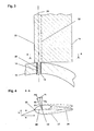
- FIG. 1 shows an underwater power plant 1 in partial sectional view.
- an outer housing 2 is used which is supported by a support structure 10.
- a support structure 10 which is supported by a support structure 10.
- embodiments are conceivable that are buoyant without a support structure 10 by buoyancy elements, in particular in the outer housing 2.
- the inner wall 3 of the outer housing 2 forms a flow channel 4, wherein the inner wall 3 is preferably designed as Konfusor / diffuser combination for flow acceleration, Within the housing 2 is a central element 5, in which the storage of water turbines and the electric generator 40 is arranged are. This will be explained in detail below FIG. 2 explained.
- FIG. 1 an underwater power plant with a first turbine stage 6.1 and a second turbine stage 6.2.
- the first turbine stage 6.1 comprises the guide vanes of the first stage 7.1, 7.2 and the turbine blades of the first stage 11.1, 11.2. 11.3.
- the second turbine stage 6.2 comprises the second stage stator blades 8.1, 8.2, 8.3 and the second stage turbine blades 12.1, 12.2.
- Both turbine stages 6.1, 6.2 are associated with the vanes of the central distributor 9.1, 9.2, 9.3, which are arranged between the turbine blades of the first stage 11.1, 11.2 and the turbine blades of the second stage 12.1, 12.2, 12.3 and which serve in the two-stage Arrangement to reduce the swirl, which is generated by the turbine blades of the respective preceding stage, so that the turbine blades of both stages are flown as consistently as possible.
- FIG. 2 which explains an enlarged section of FIG. 1 represents in the region of the central element 5.
- the same reference numerals are used for matching components.
- the turbine blades of the first stage 11.1, 11.2, 11.3 are rotatably mounted on a first hub 16.1.
- a first axle stub 17.1 is sketched for the turbine blade of the first stage 11.1, which ends radially inward of the hollow first hub 16.1 with a locking element 15.
- the turbine blade of the second stage 12.1 is pivotally attached to a second hub 16.2 by means of the second axle stub 17.2.
- the first hub 16.1 and the second hub 16.2 are connected via the machine carrier 18 and form a unit rotating in the same direction.
- the generator rotor 19 of the electric generator 40 is arranged on the machine carrier 18.
- the generator stator 21 Opposite and spaced by the air gap 20 is the generator stator 21, which is in contact with an intermediate housing part 22 of the central element 5 for improving the thermal connection.
- the central element 5 comprises a first hood 23, which are supported by means of the guide vanes of the first stage 7.1, 7.2 against the outer housing 2.
- a second hood 24 is provided, which is supported by the guide vanes of the second stage 8.1, 8.2, 8.3 to the outside.
- a first thrust bearing 26.1 In the first hood 23 is a first thrust bearing 26.1 and in the second hood 24, a second thrust bearing 26.2 is provided, which serve the axial support of the rotating unit.
- the first radial bearing 25.1, the second radial bearing 25.2, the third radial bearing 25.3 and the fourth radial bearing 25.4 are arranged on the first hood 23, the middle housing part 22 and the second hood 24.
- the said bearing can be designed as a roller bearing with loss lubrication, but preferably the storage is realized by means of water-lubricated plain bearings, which is dispensed with shaft seals for a preferred embodiment and storage area and the air gap 20 of the electric generator 40 are flooded.
- the components of the generator rotor 19 and the generator stator 21 are executed by a potting compound or a canned water-resistant.
- FIG. 3 shows an exemplary axial section through a turbine blade 11, which is placed in the plane of rotation. Shown is the neutral position of the turbine blade 11, which also consists of the in FIG. 4 shown section AA as a solid profile 27 results.
- the pivot axis 28 can be seen, which is determined on the hub 13 due to the rotatable articulation by the axle stub 14.
- the receiving opening for the Achsstutzen 14 in the hub 13 is lined by a bearing sleeve 29, so that the turbine blade 11th with respect to its angle of attack against the plane of rotation during operation freely depending on the aufschwenkenden torque and the returning moments sets.
- the pivot axis 28 is located between the Auffädelline the hydrodynamic centers 32 and the flown Profilnase 33rd
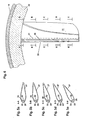
- FIGS. 5a-5e and 6 an embodiment of the invention is shown, which can be used particularly advantageous for the formation of an air turbine of an OWC wave power plant in addition to the present water turbines of a tidal power plant.
- the passive Blattwinkelverstellmechanismus is designed so that for the turbine blade 11 during operation in the radially outer region, a smaller Auswenkwinkel d arises from the plane of rotation compared to the radially inner regions.
- a possible embodiment is to provide a torsion-elastic profile 27, which has a stiffener 35 in the interior between the flown profile nose 33 and the hydrodynamic center 32, which defines a Torsionsachse. According to the terminology used in the present application, this is referred to below as the pivot axis 28.
- a generator rotor 19 is provided for the in FIG. 6 embodiment shown on the outer support ring 36. Further, the entire mounting of the rotating unit can be realized on a large outer radius, so that there is no need to provide a central element 5 according to the preceding embodiments
- FIGS. 7a-7c and 8 A further alternative design of a passive blade angle adjustment mechanism is shown, which allows a greater swinging in the radially inner region of the turbine blade.
- This is the in FIG. 8 Segmented turbine blade shown as a section through the plane of rotation.
- a three-part structure with a first segment 41, a second segment 42 and a third segment 43 is used.
- Each segment 41, 42, 43 can perform a rotational movement about a pivot pin 44 extending from the hub 13.
- a passage opening is provided in each segment 41, 42, 43, in each of which a bearing sleeve 46.1, 46.2, 46.3 is arranged from a sliding bearing material.
- spacers 41, 42, 43 are arranged between the individual segments.
- FIG. 9 shows an embodiment of an underwater power plant according to the invention with reference to a partial sectional view of a two-stage turbine arrangement.
- Radially outside the turbine blades 11.1, 11.2, 11.3, 12.1, 12.2, 12.3 of the respective stage are fixed in a torsionally rigid manner to a first outer ring 38 and a second outer ring 39.
- the profile of the respective turbine blade is aligned radially outward with the plane of rotation, while pivoting radially on the inside is possible.
- the first outer ring 38 runs in a first groove 48 in the outer housing and is supported by the bearing components 47.1, 47.2. Accordingly, a second groove 49 with the bearing components 47.3, 47.4 is provided for the second outer ring 39. Furthermore, the present embodiment can be transferred to the air turbine of a wave power plant.
- a speed or torque guidance of the turbine is effected by the directly coupled generator 40.
- a search algorithm based on an MPP controller is used for the manipulated variable specification, in this case the load torque at the electric generator 40.
- torsionally elastic turbine blades can be pivoted on an outer and an inner ring, which is set by differently set stops the maximum Aufschwenkwinkel radially inside larger than radially outside.
- the arrangement of the generator components and the associated storage can be done radially outside or radially inside.
- the distributor at least partially movable, so that there is a further possibility of adaptation to the direction and the speed of the flow.
Landscapes
- Engineering & Computer Science (AREA)
- Chemical & Material Sciences (AREA)
- Combustion & Propulsion (AREA)
- Mechanical Engineering (AREA)
- General Engineering & Computer Science (AREA)
- Life Sciences & Earth Sciences (AREA)
- General Life Sciences & Earth Sciences (AREA)
- Oceanography (AREA)
- Other Liquid Machine Or Engine Such As Wave Power Use (AREA)
- Hydraulic Turbines (AREA)
Claims (7)
- Centrale immergée comprenant1.1 un générateur électrique (40);1.2 une turbine à eau tournant dans le même sens et exposée à un écoulement bidirectionnel, possédant une pluralité de pales de turbine (11), lesquelles présentent un profil en forme de goutte sur au moins une partie de leur étendue longitudinale et où la turbine à eau comprend un mécanisme passif de réglage d'angle de calage de pale pour les pales de turbine (11),1.3 caractérisée en ce que le mécanisme de réglage d'angle de calage de pale1.4 provoque un petit angle d'ouverture par pivotement en fonction du rayon (d), où l'angle d'ouverture par pivotement (d) dans les zones radialement externes de la pale de turbine est plus petit que dans les zones radialement internes,
et où un axe de pivotement (28) est associé à chaque pale de turbine (11), axe situé entre le bord d'attaque (33) balayé par le flux et la ligne d'empilage des centres hydrodynamiques (31). - Centrale immergée selon la revendication 1, caractérisée en ce qu'au moins une partie des pales de turbine est divisée en segments (41, 42, 43, 44) individuels s'étendant radialement.
- Centrale immergée selon l'une quelconque des revendications 1 ou 2, caractérisée en ce que les pales de turbine sont élastiques en torsion et sont dirigées radialement vers l'intérieur à partir d'une bague porteuse externe (36).
- Centrale immergée selon l'une quelconque des revendications 1 à 3, caractérisée en ce que les pales de turbine sont fixées en rotation au niveau d'une bague externe (38, 39) et sont articulées de manière pivotante sur un moyeu (30) agencé radialement à l'intérieur par rapport à celle-ci.
- Turbine à air possédant une pluralité de pales de turbine (11), qui présentent un profil en forme de goutte sur au moins une partie de leur étendue longitudinale, où la turbine à air tourne dans le même sens en présence d'un balayage bidirectionnel; et où la turbine à air comprend un mécanisme passif de réglage d'angle de calage de pale pour les pales de turbine (11), où un axe de pivotement (28) est associé à chaque pale de turbine (11), axe situé entre le bord d'attaque (33) balayé par le flux et la ligne d'empilage des centres hydrodynamiques (31); caractérisée en ce que pendant l'exploitation, l'angle d'ouverture par pivotement (d) dans les zones radialement externes de la pale de turbine est plus petit que dans les zones radialement internes.
- Turbine à air (1) selon la revendication 1, caractérisée en ce que les pales de turbine sont élastiques en torsion et sont dirigées radialement vers l'intérieur à partir d'une bague porteuse externe (36) ou sont fixées en rotation au niveau d'une bague externe (38, 39) et sont articulées de manière pivotante sur un moyeu (30) agencé radialement à l'intérieur par rapport à celle-ci.
- Turbine à air selon l'une quelconque des revendications 5 ou 6, caractérisée en ce qu'au moins une partie des pales de turbine est divisée en segments (41, 42, 43, 44) individuels s'étendant radialement.
Applications Claiming Priority (2)
| Application Number | Priority Date | Filing Date | Title |
|---|---|---|---|
| DE102009018758A DE102009018758A1 (de) | 2009-04-27 | 2009-04-27 | Unterwasserkraftwerk mit einer bidirektional anströmbaren, gleichsinnig umlaufenden Wasserturbine |
| PCT/EP2010/002059 WO2010124778A2 (fr) | 2009-04-27 | 2010-03-31 | Centrale électrique immergée équipée d'une turbine hydraulique tournant dans le même sens et à écoulement bidirectionnel |
Publications (2)
| Publication Number | Publication Date |
|---|---|
| EP2425124A2 EP2425124A2 (fr) | 2012-03-07 |
| EP2425124B1 true EP2425124B1 (fr) | 2013-03-27 |
Family
ID=42779713
Family Applications (1)
| Application Number | Title | Priority Date | Filing Date |
|---|---|---|---|
| EP10718061A Not-in-force EP2425124B1 (fr) | 2009-04-27 | 2010-03-31 | Centrale électrique immergée équipée d'une turbine hydraulique tournant dans le même sens et à écoulement bidirectionnel |
Country Status (5)
| Country | Link |
|---|---|
| EP (1) | EP2425124B1 (fr) |
| DE (1) | DE102009018758A1 (fr) |
| ES (1) | ES2403232T3 (fr) |
| PT (1) | PT2425124E (fr) |
| WO (1) | WO2010124778A2 (fr) |
Cited By (1)
| Publication number | Priority date | Publication date | Assignee | Title |
|---|---|---|---|---|
| WO2024085773A2 (fr) | 2022-10-20 | 2024-04-25 | Felicianne As | Convertisseur bidirectionnel d'énergie houlomotrice |
Families Citing this family (4)
| Publication number | Priority date | Publication date | Assignee | Title |
|---|---|---|---|---|
| WO2012005413A1 (fr) * | 2010-07-09 | 2012-01-12 | 인하대학교 산학협력단 | Lame de rotor séparable pour produire l'énergie de courant de marée |
| CN103147904B (zh) * | 2013-02-21 | 2015-06-24 | 哈尔滨电机厂有限责任公司 | 潮流发电使用的双斜臂旋转机构 |
| DE202017102221U1 (de) * | 2017-04-12 | 2018-07-13 | Rolf Rohden | Turbine und Gezeitenkraftwerk |
| CN113202686B (zh) * | 2021-03-21 | 2023-12-26 | 济南荣庆节能技术有限公司 | 利用潮汐能发电的装备 |
Family Cites Families (11)
| Publication number | Priority date | Publication date | Assignee | Title |
|---|---|---|---|---|
| CH316900A (de) | 1953-04-15 | 1956-10-31 | Escher Wyss Ag | Hydroelektrische Maschinenanlage mit gegenläufigen Laufrädern |
| GB1574379A (en) | 1977-08-24 | 1980-09-03 | English Electric Co Ltd | Turbines and like rotary machines |
| GB2140810B (en) | 1983-05-24 | 1987-07-08 | Celltech Ltd | Polypeptide and protein products, and process for their production |
| JPS6098103A (ja) * | 1983-11-02 | 1985-06-01 | Tohoku Electric Power Co Inc | 可動翼空気タ−ビン装置 |
| JPS63219801A (ja) * | 1987-03-06 | 1988-09-13 | Saga Univ | 自己可変ピツチ翼を有する波力発電用タ−ビン |
| US6116856A (en) | 1998-09-18 | 2000-09-12 | Patterson Technique, Inc. | Bi-directional fan having asymmetric, reversible blades |
| JP4024208B2 (ja) | 2001-09-17 | 2007-12-19 | クリーン カーレント パワー システムズ インコーポレイテッド | 水中用ダクテッドタービン |
| GB2392713B (en) * | 2003-09-13 | 2004-10-13 | John Hunter | Multi-direction flow power turbine |
| US20050271508A1 (en) | 2004-06-03 | 2005-12-08 | Asfaw Beyene | Flexible turbine blade |
| NL2000840C2 (nl) * | 2007-08-31 | 2009-03-03 | Tocardo B V | Inrichting voor het omzetten van kinetische energie van een stromend water in kinetische energie van een roteerbare rotoras. |
| DE102008051370A1 (de) * | 2008-10-15 | 2010-04-22 | Voith Patent Gmbh | Unterwasserkraftwerk mit passiver Leistungsregelung |
-
2009
- 2009-04-27 DE DE102009018758A patent/DE102009018758A1/de not_active Withdrawn
-
2010
- 2010-03-31 PT PT107180614T patent/PT2425124E/pt unknown
- 2010-03-31 ES ES10718061T patent/ES2403232T3/es active Active
- 2010-03-31 WO PCT/EP2010/002059 patent/WO2010124778A2/fr not_active Ceased
- 2010-03-31 EP EP10718061A patent/EP2425124B1/fr not_active Not-in-force
Cited By (1)
| Publication number | Priority date | Publication date | Assignee | Title |
|---|---|---|---|---|
| WO2024085773A2 (fr) | 2022-10-20 | 2024-04-25 | Felicianne As | Convertisseur bidirectionnel d'énergie houlomotrice |
Also Published As
| Publication number | Publication date |
|---|---|
| ES2403232T3 (es) | 2013-05-16 |
| WO2010124778A3 (fr) | 2011-06-30 |
| DE102009018758A1 (de) | 2010-10-28 |
| WO2010124778A2 (fr) | 2010-11-04 |
| EP2425124A2 (fr) | 2012-03-07 |
| PT2425124E (pt) | 2013-04-19 |
Similar Documents
| Publication | Publication Date | Title |
|---|---|---|
| DE69404179T2 (de) | Windkraftmaschine | |
| EP1255931B1 (fr) | Eolienne dotee de deux rotors situes l'un derriere l'autre | |
| EP2235365B1 (fr) | Éolienne | |
| EP1002949A2 (fr) | Eolienne à axe vertical | |
| EP2655874B1 (fr) | Rotor d'éolienne éolienne et procédé de production énergétique | |
| DE102010011708A1 (de) | Turbine mit passiver Schaufelverstellung | |
| EP2425124B1 (fr) | Centrale électrique immergée équipée d'une turbine hydraulique tournant dans le même sens et à écoulement bidirectionnel | |
| EP2729695B1 (fr) | Centrale hydromotrice et procédé pour la faire fonctionner | |
| EP4374064A1 (fr) | Installation de production de force d'écoulement dotée d'ailettes pivotantes | |
| DE102008051370A1 (de) | Unterwasserkraftwerk mit passiver Leistungsregelung | |
| EP1387954B1 (fr) | Eolienne a axe vertical | |
| EP2522847B1 (fr) | Parque de centrales d'énergie hydraulique et son procédé de fabrication | |
| DE102009051117B4 (de) | Horizontalläufer-Turbine mit passiver Gierwinkel-Einstellvorrichtung | |
| EP3878732B1 (fr) | Procédé et dispositif de réglage des caractéristiques de débit d'une hélice | |
| EP4189235B1 (fr) | Hélice universelle, procédé de fonctionnement et utilisations privilégiées | |
| WO2009089902A2 (fr) | Turbine à air pour centrale houlomotrice | |
| EP2920454B1 (fr) | Dispositif pour exploiter l'énergie cinétique d'un fluide en écoulement | |
| DE2930073A1 (de) | Windenergiekonverter | |
| EP2521856B1 (fr) | Centrale hydromotrice et procédé pour la faire fonctionner | |
| EP2636892A2 (fr) | Installation éolienne et procédé de production d'énergie rotative par le vent | |
| WO2011100953A2 (fr) | Centrale électrique à écoulement | |
| DE202008010290U1 (de) | Windkraft nach dem Darrieus-Prinzip | |
| DE3590007T1 (de) | Windrotor | |
| DE10251388A1 (de) | Rotor einer Windkraftanlage | |
| EP3628858A1 (fr) | Turbine hydraulique |
Legal Events
| Date | Code | Title | Description |
|---|---|---|---|
| PUAI | Public reference made under article 153(3) epc to a published international application that has entered the european phase |
Free format text: ORIGINAL CODE: 0009012 |
|
| 17P | Request for examination filed |
Effective date: 20110913 |
|
| AK | Designated contracting states |
Kind code of ref document: A2 Designated state(s): AT BE BG CH CY CZ DE DK EE ES FI FR GB GR HR HU IE IS IT LI LT LU LV MC MK MT NL NO PL PT RO SE SI SK SM TR |
|
| DAX | Request for extension of the european patent (deleted) | ||
| GRAP | Despatch of communication of intention to grant a patent |
Free format text: ORIGINAL CODE: EPIDOSNIGR1 |
|
| RIC1 | Information provided on ipc code assigned before grant |
Ipc: F03B 17/06 20060101AFI20121205BHEP Ipc: F03B 13/26 20060101ALI20121205BHEP |
|
| GRAS | Grant fee paid |
Free format text: ORIGINAL CODE: EPIDOSNIGR3 |
|
| GRAA | (expected) grant |
Free format text: ORIGINAL CODE: 0009210 |
|
| AK | Designated contracting states |
Kind code of ref document: B1 Designated state(s): AT BE BG CH CY CZ DE DK EE ES FI FR GB GR HR HU IE IS IT LI LT LU LV MC MK MT NL NO PL PT RO SE SI SK SM TR |
|
| REG | Reference to a national code |
Ref country code: GB Ref legal event code: FG4D Free format text: NOT ENGLISH |
|
| REG | Reference to a national code |
Ref country code: CH Ref legal event code: EP |
|
| REG | Reference to a national code |
Ref country code: AT Ref legal event code: REF Ref document number: 603567 Country of ref document: AT Kind code of ref document: T Effective date: 20130415 |
|
| REG | Reference to a national code |
Ref country code: PT Ref legal event code: SC4A Free format text: AVAILABILITY OF NATIONAL TRANSLATION Effective date: 20130415 |
|
| REG | Reference to a national code |
Ref country code: IE Ref legal event code: FG4D Free format text: LANGUAGE OF EP DOCUMENT: GERMAN |
|
| REG | Reference to a national code |
Ref country code: ES Ref legal event code: FG2A Ref document number: 2403232 Country of ref document: ES Kind code of ref document: T3 Effective date: 20130516 |
|
| REG | Reference to a national code |
Ref country code: DE Ref legal event code: R096 Ref document number: 502010002720 Country of ref document: DE Effective date: 20130529 |
|
| REG | Reference to a national code |
Ref country code: NO Ref legal event code: T2 Effective date: 20130327 |
|
| PG25 | Lapsed in a contracting state [announced via postgrant information from national office to epo] |
Ref country code: LT Free format text: LAPSE BECAUSE OF FAILURE TO SUBMIT A TRANSLATION OF THE DESCRIPTION OR TO PAY THE FEE WITHIN THE PRESCRIBED TIME-LIMIT Effective date: 20130327 Ref country code: BG Free format text: LAPSE BECAUSE OF FAILURE TO SUBMIT A TRANSLATION OF THE DESCRIPTION OR TO PAY THE FEE WITHIN THE PRESCRIBED TIME-LIMIT Effective date: 20130627 Ref country code: SE Free format text: LAPSE BECAUSE OF FAILURE TO SUBMIT A TRANSLATION OF THE DESCRIPTION OR TO PAY THE FEE WITHIN THE PRESCRIBED TIME-LIMIT Effective date: 20130327 |
|
| REG | Reference to a national code |
Ref country code: LT Ref legal event code: MG4D |
|
| PG25 | Lapsed in a contracting state [announced via postgrant information from national office to epo] |
Ref country code: LV Free format text: LAPSE BECAUSE OF FAILURE TO SUBMIT A TRANSLATION OF THE DESCRIPTION OR TO PAY THE FEE WITHIN THE PRESCRIBED TIME-LIMIT Effective date: 20130327 Ref country code: GR Free format text: LAPSE BECAUSE OF FAILURE TO SUBMIT A TRANSLATION OF THE DESCRIPTION OR TO PAY THE FEE WITHIN THE PRESCRIBED TIME-LIMIT Effective date: 20130628 Ref country code: FI Free format text: LAPSE BECAUSE OF FAILURE TO SUBMIT A TRANSLATION OF THE DESCRIPTION OR TO PAY THE FEE WITHIN THE PRESCRIBED TIME-LIMIT Effective date: 20130327 Ref country code: SI Free format text: LAPSE BECAUSE OF FAILURE TO SUBMIT A TRANSLATION OF THE DESCRIPTION OR TO PAY THE FEE WITHIN THE PRESCRIBED TIME-LIMIT Effective date: 20130327 |
|
| REG | Reference to a national code |
Ref country code: NL Ref legal event code: VDEP Effective date: 20130327 |
|
| BERE | Be: lapsed |
Owner name: VOITH PATENT G.M.B.H. Effective date: 20130331 |
|
| PG25 | Lapsed in a contracting state [announced via postgrant information from national office to epo] |
Ref country code: HR Free format text: LAPSE BECAUSE OF FAILURE TO SUBMIT A TRANSLATION OF THE DESCRIPTION OR TO PAY THE FEE WITHIN THE PRESCRIBED TIME-LIMIT Effective date: 20130327 |
|
| PG25 | Lapsed in a contracting state [announced via postgrant information from national office to epo] |
Ref country code: RO Free format text: LAPSE BECAUSE OF FAILURE TO SUBMIT A TRANSLATION OF THE DESCRIPTION OR TO PAY THE FEE WITHIN THE PRESCRIBED TIME-LIMIT Effective date: 20130327 Ref country code: SK Free format text: LAPSE BECAUSE OF FAILURE TO SUBMIT A TRANSLATION OF THE DESCRIPTION OR TO PAY THE FEE WITHIN THE PRESCRIBED TIME-LIMIT Effective date: 20130327 Ref country code: EE Free format text: LAPSE BECAUSE OF FAILURE TO SUBMIT A TRANSLATION OF THE DESCRIPTION OR TO PAY THE FEE WITHIN THE PRESCRIBED TIME-LIMIT Effective date: 20130327 Ref country code: NL Free format text: LAPSE BECAUSE OF FAILURE TO SUBMIT A TRANSLATION OF THE DESCRIPTION OR TO PAY THE FEE WITHIN THE PRESCRIBED TIME-LIMIT Effective date: 20130327 Ref country code: MC Free format text: LAPSE BECAUSE OF NON-PAYMENT OF DUE FEES Effective date: 20130331 Ref country code: IS Free format text: LAPSE BECAUSE OF FAILURE TO SUBMIT A TRANSLATION OF THE DESCRIPTION OR TO PAY THE FEE WITHIN THE PRESCRIBED TIME-LIMIT Effective date: 20130727 Ref country code: CZ Free format text: LAPSE BECAUSE OF FAILURE TO SUBMIT A TRANSLATION OF THE DESCRIPTION OR TO PAY THE FEE WITHIN THE PRESCRIBED TIME-LIMIT Effective date: 20130327 |
|
| PG25 | Lapsed in a contracting state [announced via postgrant information from national office to epo] |
Ref country code: PL Free format text: LAPSE BECAUSE OF FAILURE TO SUBMIT A TRANSLATION OF THE DESCRIPTION OR TO PAY THE FEE WITHIN THE PRESCRIBED TIME-LIMIT Effective date: 20130327 Ref country code: CY Free format text: LAPSE BECAUSE OF FAILURE TO SUBMIT A TRANSLATION OF THE DESCRIPTION OR TO PAY THE FEE WITHIN THE PRESCRIBED TIME-LIMIT Effective date: 20130327 |
|
| REG | Reference to a national code |
Ref country code: IE Ref legal event code: MM4A |
|
| PG25 | Lapsed in a contracting state [announced via postgrant information from national office to epo] |
Ref country code: DK Free format text: LAPSE BECAUSE OF FAILURE TO SUBMIT A TRANSLATION OF THE DESCRIPTION OR TO PAY THE FEE WITHIN THE PRESCRIBED TIME-LIMIT Effective date: 20130327 Ref country code: BE Free format text: LAPSE BECAUSE OF NON-PAYMENT OF DUE FEES Effective date: 20130331 Ref country code: IE Free format text: LAPSE BECAUSE OF NON-PAYMENT OF DUE FEES Effective date: 20130331 |
|
| PLBE | No opposition filed within time limit |
Free format text: ORIGINAL CODE: 0009261 |
|
| STAA | Information on the status of an ep patent application or granted ep patent |
Free format text: STATUS: NO OPPOSITION FILED WITHIN TIME LIMIT |
|
| PG25 | Lapsed in a contracting state [announced via postgrant information from national office to epo] |
Ref country code: IT Free format text: LAPSE BECAUSE OF FAILURE TO SUBMIT A TRANSLATION OF THE DESCRIPTION OR TO PAY THE FEE WITHIN THE PRESCRIBED TIME-LIMIT Effective date: 20130327 |
|
| 26N | No opposition filed |
Effective date: 20140103 |
|
| REG | Reference to a national code |
Ref country code: DE Ref legal event code: R097 Ref document number: 502010002720 Country of ref document: DE Effective date: 20140103 |
|
| PG25 | Lapsed in a contracting state [announced via postgrant information from national office to epo] |
Ref country code: MT Free format text: LAPSE BECAUSE OF FAILURE TO SUBMIT A TRANSLATION OF THE DESCRIPTION OR TO PAY THE FEE WITHIN THE PRESCRIBED TIME-LIMIT Effective date: 20130327 |
|
| REG | Reference to a national code |
Ref country code: CH Ref legal event code: PL |
|
| PG25 | Lapsed in a contracting state [announced via postgrant information from national office to epo] |
Ref country code: LI Free format text: LAPSE BECAUSE OF NON-PAYMENT OF DUE FEES Effective date: 20140331 Ref country code: CH Free format text: LAPSE BECAUSE OF NON-PAYMENT OF DUE FEES Effective date: 20140331 |
|
| REG | Reference to a national code |
Ref country code: FR Ref legal event code: PLFP Year of fee payment: 6 |
|
| PGFP | Annual fee paid to national office [announced via postgrant information from national office to epo] |
Ref country code: NO Payment date: 20150312 Year of fee payment: 6 Ref country code: PT Payment date: 20150330 Year of fee payment: 6 Ref country code: DE Payment date: 20150320 Year of fee payment: 6 Ref country code: ES Payment date: 20150326 Year of fee payment: 6 |
|
| PG25 | Lapsed in a contracting state [announced via postgrant information from national office to epo] |
Ref country code: SM Free format text: LAPSE BECAUSE OF FAILURE TO SUBMIT A TRANSLATION OF THE DESCRIPTION OR TO PAY THE FEE WITHIN THE PRESCRIBED TIME-LIMIT Effective date: 20130327 |
|
| PGFP | Annual fee paid to national office [announced via postgrant information from national office to epo] |
Ref country code: FR Payment date: 20150319 Year of fee payment: 6 Ref country code: GB Payment date: 20150319 Year of fee payment: 6 |
|
| PG25 | Lapsed in a contracting state [announced via postgrant information from national office to epo] |
Ref country code: TR Free format text: LAPSE BECAUSE OF FAILURE TO SUBMIT A TRANSLATION OF THE DESCRIPTION OR TO PAY THE FEE WITHIN THE PRESCRIBED TIME-LIMIT Effective date: 20130327 |
|
| PG25 | Lapsed in a contracting state [announced via postgrant information from national office to epo] |
Ref country code: MK Free format text: LAPSE BECAUSE OF FAILURE TO SUBMIT A TRANSLATION OF THE DESCRIPTION OR TO PAY THE FEE WITHIN THE PRESCRIBED TIME-LIMIT Effective date: 20130327 Ref country code: LU Free format text: LAPSE BECAUSE OF NON-PAYMENT OF DUE FEES Effective date: 20130331 Ref country code: HU Free format text: LAPSE BECAUSE OF FAILURE TO SUBMIT A TRANSLATION OF THE DESCRIPTION OR TO PAY THE FEE WITHIN THE PRESCRIBED TIME-LIMIT; INVALID AB INITIO Effective date: 20100331 |
|
| REG | Reference to a national code |
Ref country code: AT Ref legal event code: MM01 Ref document number: 603567 Country of ref document: AT Kind code of ref document: T Effective date: 20150331 |
|
| PG25 | Lapsed in a contracting state [announced via postgrant information from national office to epo] |
Ref country code: AT Free format text: LAPSE BECAUSE OF NON-PAYMENT OF DUE FEES Effective date: 20150331 |
|
| REG | Reference to a national code |
Ref country code: DE Ref legal event code: R119 Ref document number: 502010002720 Country of ref document: DE |
|
| REG | Reference to a national code |
Ref country code: NO Ref legal event code: MMEP |
|
| GBPC | Gb: european patent ceased through non-payment of renewal fee |
Effective date: 20160331 |
|
| PG25 | Lapsed in a contracting state [announced via postgrant information from national office to epo] |
Ref country code: PT Free format text: LAPSE BECAUSE OF NON-PAYMENT OF DUE FEES Effective date: 20160930 |
|
| REG | Reference to a national code |
Ref country code: FR Ref legal event code: ST Effective date: 20161130 |
|
| PG25 | Lapsed in a contracting state [announced via postgrant information from national office to epo] |
Ref country code: GB Free format text: LAPSE BECAUSE OF NON-PAYMENT OF DUE FEES Effective date: 20160331 Ref country code: DE Free format text: LAPSE BECAUSE OF NON-PAYMENT OF DUE FEES Effective date: 20161001 Ref country code: NO Free format text: LAPSE BECAUSE OF NON-PAYMENT OF DUE FEES Effective date: 20160331 Ref country code: FR Free format text: LAPSE BECAUSE OF NON-PAYMENT OF DUE FEES Effective date: 20160331 |
|
| REG | Reference to a national code |
Ref country code: ES Ref legal event code: FD2A Effective date: 20170428 |
|
| PG25 | Lapsed in a contracting state [announced via postgrant information from national office to epo] |
Ref country code: ES Free format text: LAPSE BECAUSE OF NON-PAYMENT OF DUE FEES Effective date: 20160401 |