EP2424724B2 - Ultraschallsiegelvorrichtung und verfahren zum versiegeln von materialbahnen - Google Patents
Ultraschallsiegelvorrichtung und verfahren zum versiegeln von materialbahnen Download PDFInfo
- Publication number
- EP2424724B2 EP2424724B2 EP10719927.5A EP10719927A EP2424724B2 EP 2424724 B2 EP2424724 B2 EP 2424724B2 EP 10719927 A EP10719927 A EP 10719927A EP 2424724 B2 EP2424724 B2 EP 2424724B2
- Authority
- EP
- European Patent Office
- Prior art keywords
- anvil
- sonotrode
- welding
- counterforce
- temperature
- Prior art date
- Legal status (The legal status is an assumption and is not a legal conclusion. Google has not performed a legal analysis and makes no representation as to the accuracy of the status listed.)
- Active
Links
Images


Classifications
-
- B—PERFORMING OPERATIONS; TRANSPORTING
- B29—WORKING OF PLASTICS; WORKING OF SUBSTANCES IN A PLASTIC STATE IN GENERAL
- B29C—SHAPING OR JOINING OF PLASTICS; SHAPING OF MATERIAL IN A PLASTIC STATE, NOT OTHERWISE PROVIDED FOR; AFTER-TREATMENT OF THE SHAPED PRODUCTS, e.g. REPAIRING
- B29C65/00—Joining or sealing of preformed parts, e.g. welding of plastics materials; Apparatus therefor
- B29C65/02—Joining or sealing of preformed parts, e.g. welding of plastics materials; Apparatus therefor by heating, with or without pressure
- B29C65/08—Joining or sealing of preformed parts, e.g. welding of plastics materials; Apparatus therefor by heating, with or without pressure using ultrasonic vibrations
-
- B—PERFORMING OPERATIONS; TRANSPORTING
- B29—WORKING OF PLASTICS; WORKING OF SUBSTANCES IN A PLASTIC STATE IN GENERAL
- B29C—SHAPING OR JOINING OF PLASTICS; SHAPING OF MATERIAL IN A PLASTIC STATE, NOT OTHERWISE PROVIDED FOR; AFTER-TREATMENT OF THE SHAPED PRODUCTS, e.g. REPAIRING
- B29C65/00—Joining or sealing of preformed parts, e.g. welding of plastics materials; Apparatus therefor
- B29C65/02—Joining or sealing of preformed parts, e.g. welding of plastics materials; Apparatus therefor by heating, with or without pressure
- B29C65/18—Joining or sealing of preformed parts, e.g. welding of plastics materials; Apparatus therefor by heating, with or without pressure using heated tools
-
- B—PERFORMING OPERATIONS; TRANSPORTING
- B29—WORKING OF PLASTICS; WORKING OF SUBSTANCES IN A PLASTIC STATE IN GENERAL
- B29C—SHAPING OR JOINING OF PLASTICS; SHAPING OF MATERIAL IN A PLASTIC STATE, NOT OTHERWISE PROVIDED FOR; AFTER-TREATMENT OF THE SHAPED PRODUCTS, e.g. REPAIRING
- B29C65/00—Joining or sealing of preformed parts, e.g. welding of plastics materials; Apparatus therefor
- B29C65/72—Joining or sealing of preformed parts, e.g. welding of plastics materials; Apparatus therefor by combined operations or combined techniques, e.g. welding and stitching
-
- B—PERFORMING OPERATIONS; TRANSPORTING
- B29—WORKING OF PLASTICS; WORKING OF SUBSTANCES IN A PLASTIC STATE IN GENERAL
- B29C—SHAPING OR JOINING OF PLASTICS; SHAPING OF MATERIAL IN A PLASTIC STATE, NOT OTHERWISE PROVIDED FOR; AFTER-TREATMENT OF THE SHAPED PRODUCTS, e.g. REPAIRING
- B29C66/00—General aspects of processes or apparatus for joining preformed parts
- B29C66/01—General aspects dealing with the joint area or with the area to be joined
- B29C66/05—Particular design of joint configurations
- B29C66/10—Particular design of joint configurations particular design of the joint cross-sections
- B29C66/11—Joint cross-sections comprising a single joint-segment, i.e. one of the parts to be joined comprising a single joint-segment in the joint cross-section
- B29C66/112—Single lapped joints
- B29C66/1122—Single lap to lap joints, i.e. overlap joints
-
- B—PERFORMING OPERATIONS; TRANSPORTING
- B29—WORKING OF PLASTICS; WORKING OF SUBSTANCES IN A PLASTIC STATE IN GENERAL
- B29C—SHAPING OR JOINING OF PLASTICS; SHAPING OF MATERIAL IN A PLASTIC STATE, NOT OTHERWISE PROVIDED FOR; AFTER-TREATMENT OF THE SHAPED PRODUCTS, e.g. REPAIRING
- B29C66/00—General aspects of processes or apparatus for joining preformed parts
- B29C66/01—General aspects dealing with the joint area or with the area to be joined
- B29C66/05—Particular design of joint configurations
- B29C66/20—Particular design of joint configurations particular design of the joint lines, e.g. of the weld lines
- B29C66/23—Particular design of joint configurations particular design of the joint lines, e.g. of the weld lines said joint lines being multiple and parallel or being in the form of tessellations
- B29C66/232—Particular design of joint configurations particular design of the joint lines, e.g. of the weld lines said joint lines being multiple and parallel or being in the form of tessellations said joint lines being multiple and parallel, i.e. the joint being formed by several parallel joint lines
-
- B—PERFORMING OPERATIONS; TRANSPORTING
- B29—WORKING OF PLASTICS; WORKING OF SUBSTANCES IN A PLASTIC STATE IN GENERAL
- B29C—SHAPING OR JOINING OF PLASTICS; SHAPING OF MATERIAL IN A PLASTIC STATE, NOT OTHERWISE PROVIDED FOR; AFTER-TREATMENT OF THE SHAPED PRODUCTS, e.g. REPAIRING
- B29C66/00—General aspects of processes or apparatus for joining preformed parts
- B29C66/40—General aspects of joining substantially flat articles, e.g. plates, sheets or web-like materials; Making flat seams in tubular or hollow articles; Joining single elements to substantially flat surfaces
- B29C66/41—Joining substantially flat articles ; Making flat seams in tubular or hollow articles
- B29C66/43—Joining a relatively small portion of the surface of said articles
-
- B—PERFORMING OPERATIONS; TRANSPORTING
- B29—WORKING OF PLASTICS; WORKING OF SUBSTANCES IN A PLASTIC STATE IN GENERAL
- B29C—SHAPING OR JOINING OF PLASTICS; SHAPING OF MATERIAL IN A PLASTIC STATE, NOT OTHERWISE PROVIDED FOR; AFTER-TREATMENT OF THE SHAPED PRODUCTS, e.g. REPAIRING
- B29C66/00—General aspects of processes or apparatus for joining preformed parts
- B29C66/80—General aspects of machine operations or constructions and parts thereof
- B29C66/81—General aspects of the pressing elements, i.e. the elements applying pressure on the parts to be joined in the area to be joined, e.g. the welding jaws or clamps
- B29C66/814—General aspects of the pressing elements, i.e. the elements applying pressure on the parts to be joined in the area to be joined, e.g. the welding jaws or clamps characterised by the design of the pressing elements, e.g. of the welding jaws or clamps
- B29C66/8141—General aspects of the pressing elements, i.e. the elements applying pressure on the parts to be joined in the area to be joined, e.g. the welding jaws or clamps characterised by the design of the pressing elements, e.g. of the welding jaws or clamps characterised by the surface geometry of the part of the pressing elements, e.g. welding jaws or clamps, coming into contact with the parts to be joined
- B29C66/81411—General aspects of the pressing elements, i.e. the elements applying pressure on the parts to be joined in the area to be joined, e.g. the welding jaws or clamps characterised by the design of the pressing elements, e.g. of the welding jaws or clamps characterised by the surface geometry of the part of the pressing elements, e.g. welding jaws or clamps, coming into contact with the parts to be joined characterised by its cross-section, e.g. transversal or longitudinal, being non-flat
- B29C66/81421—General aspects of the pressing elements, i.e. the elements applying pressure on the parts to be joined in the area to be joined, e.g. the welding jaws or clamps characterised by the design of the pressing elements, e.g. of the welding jaws or clamps characterised by the surface geometry of the part of the pressing elements, e.g. welding jaws or clamps, coming into contact with the parts to be joined characterised by its cross-section, e.g. transversal or longitudinal, being non-flat being convex or concave
- B29C66/81422—General aspects of the pressing elements, i.e. the elements applying pressure on the parts to be joined in the area to be joined, e.g. the welding jaws or clamps characterised by the design of the pressing elements, e.g. of the welding jaws or clamps characterised by the surface geometry of the part of the pressing elements, e.g. welding jaws or clamps, coming into contact with the parts to be joined characterised by its cross-section, e.g. transversal or longitudinal, being non-flat being convex or concave being convex
-
- B—PERFORMING OPERATIONS; TRANSPORTING
- B29—WORKING OF PLASTICS; WORKING OF SUBSTANCES IN A PLASTIC STATE IN GENERAL
- B29C—SHAPING OR JOINING OF PLASTICS; SHAPING OF MATERIAL IN A PLASTIC STATE, NOT OTHERWISE PROVIDED FOR; AFTER-TREATMENT OF THE SHAPED PRODUCTS, e.g. REPAIRING
- B29C66/00—General aspects of processes or apparatus for joining preformed parts
- B29C66/80—General aspects of machine operations or constructions and parts thereof
- B29C66/81—General aspects of the pressing elements, i.e. the elements applying pressure on the parts to be joined in the area to be joined, e.g. the welding jaws or clamps
- B29C66/816—General aspects of the pressing elements, i.e. the elements applying pressure on the parts to be joined in the area to be joined, e.g. the welding jaws or clamps characterised by the mounting of the pressing elements, e.g. of the welding jaws or clamps
- B29C66/8161—General aspects of the pressing elements, i.e. the elements applying pressure on the parts to be joined in the area to be joined, e.g. the welding jaws or clamps characterised by the mounting of the pressing elements, e.g. of the welding jaws or clamps said pressing elements being supported or backed-up by springs or by resilient material
-
- B—PERFORMING OPERATIONS; TRANSPORTING
- B29—WORKING OF PLASTICS; WORKING OF SUBSTANCES IN A PLASTIC STATE IN GENERAL
- B29C—SHAPING OR JOINING OF PLASTICS; SHAPING OF MATERIAL IN A PLASTIC STATE, NOT OTHERWISE PROVIDED FOR; AFTER-TREATMENT OF THE SHAPED PRODUCTS, e.g. REPAIRING
- B29C66/00—General aspects of processes or apparatus for joining preformed parts
- B29C66/80—General aspects of machine operations or constructions and parts thereof
- B29C66/82—Pressure application arrangements, e.g. transmission or actuating mechanisms for joining tools or clamps
- B29C66/824—Actuating mechanisms
- B29C66/8242—Pneumatic or hydraulic drives
-
- B—PERFORMING OPERATIONS; TRANSPORTING
- B29—WORKING OF PLASTICS; WORKING OF SUBSTANCES IN A PLASTIC STATE IN GENERAL
- B29C—SHAPING OR JOINING OF PLASTICS; SHAPING OF MATERIAL IN A PLASTIC STATE, NOT OTHERWISE PROVIDED FOR; AFTER-TREATMENT OF THE SHAPED PRODUCTS, e.g. REPAIRING
- B29C66/00—General aspects of processes or apparatus for joining preformed parts
- B29C66/80—General aspects of machine operations or constructions and parts thereof
- B29C66/84—Specific machine types or machines suitable for specific applications
- B29C66/845—C-clamp type or sewing machine type
-
- B—PERFORMING OPERATIONS; TRANSPORTING
- B29—WORKING OF PLASTICS; WORKING OF SUBSTANCES IN A PLASTIC STATE IN GENERAL
- B29C—SHAPING OR JOINING OF PLASTICS; SHAPING OF MATERIAL IN A PLASTIC STATE, NOT OTHERWISE PROVIDED FOR; AFTER-TREATMENT OF THE SHAPED PRODUCTS, e.g. REPAIRING
- B29C66/00—General aspects of processes or apparatus for joining preformed parts
- B29C66/90—Measuring or controlling the joining process
- B29C66/91—Measuring or controlling the joining process by measuring or controlling the temperature, the heat or the thermal flux
- B29C66/914—Measuring or controlling the joining process by measuring or controlling the temperature, the heat or the thermal flux by controlling or regulating the temperature, the heat or the thermal flux
- B29C66/9141—Measuring or controlling the joining process by measuring or controlling the temperature, the heat or the thermal flux by controlling or regulating the temperature, the heat or the thermal flux by controlling or regulating the temperature
- B29C66/91421—Measuring or controlling the joining process by measuring or controlling the temperature, the heat or the thermal flux by controlling or regulating the temperature, the heat or the thermal flux by controlling or regulating the temperature of the joining tools
-
- B—PERFORMING OPERATIONS; TRANSPORTING
- B29—WORKING OF PLASTICS; WORKING OF SUBSTANCES IN A PLASTIC STATE IN GENERAL
- B29C—SHAPING OR JOINING OF PLASTICS; SHAPING OF MATERIAL IN A PLASTIC STATE, NOT OTHERWISE PROVIDED FOR; AFTER-TREATMENT OF THE SHAPED PRODUCTS, e.g. REPAIRING
- B29C66/00—General aspects of processes or apparatus for joining preformed parts
- B29C66/90—Measuring or controlling the joining process
- B29C66/91—Measuring or controlling the joining process by measuring or controlling the temperature, the heat or the thermal flux
- B29C66/914—Measuring or controlling the joining process by measuring or controlling the temperature, the heat or the thermal flux by controlling or regulating the temperature, the heat or the thermal flux
- B29C66/9141—Measuring or controlling the joining process by measuring or controlling the temperature, the heat or the thermal flux by controlling or regulating the temperature, the heat or the thermal flux by controlling or regulating the temperature
- B29C66/91431—Measuring or controlling the joining process by measuring or controlling the temperature, the heat or the thermal flux by controlling or regulating the temperature, the heat or the thermal flux by controlling or regulating the temperature the temperature being kept constant over time
-
- B—PERFORMING OPERATIONS; TRANSPORTING
- B29—WORKING OF PLASTICS; WORKING OF SUBSTANCES IN A PLASTIC STATE IN GENERAL
- B29C—SHAPING OR JOINING OF PLASTICS; SHAPING OF MATERIAL IN A PLASTIC STATE, NOT OTHERWISE PROVIDED FOR; AFTER-TREATMENT OF THE SHAPED PRODUCTS, e.g. REPAIRING
- B29C66/00—General aspects of processes or apparatus for joining preformed parts
- B29C66/90—Measuring or controlling the joining process
- B29C66/91—Measuring or controlling the joining process by measuring or controlling the temperature, the heat or the thermal flux
- B29C66/914—Measuring or controlling the joining process by measuring or controlling the temperature, the heat or the thermal flux by controlling or regulating the temperature, the heat or the thermal flux
- B29C66/9161—Measuring or controlling the joining process by measuring or controlling the temperature, the heat or the thermal flux by controlling or regulating the temperature, the heat or the thermal flux by controlling or regulating the heat or the thermal flux, i.e. the heat flux
-
- B—PERFORMING OPERATIONS; TRANSPORTING
- B29—WORKING OF PLASTICS; WORKING OF SUBSTANCES IN A PLASTIC STATE IN GENERAL
- B29C—SHAPING OR JOINING OF PLASTICS; SHAPING OF MATERIAL IN A PLASTIC STATE, NOT OTHERWISE PROVIDED FOR; AFTER-TREATMENT OF THE SHAPED PRODUCTS, e.g. REPAIRING
- B29C66/00—General aspects of processes or apparatus for joining preformed parts
- B29C66/90—Measuring or controlling the joining process
- B29C66/92—Measuring or controlling the joining process by measuring or controlling the pressure, the force, the mechanical power or the displacement of the joining tools
- B29C66/922—Measuring or controlling the joining process by measuring or controlling the pressure, the force, the mechanical power or the displacement of the joining tools by measuring the pressure, the force, the mechanical power or the displacement of the joining tools
- B29C66/9221—Measuring or controlling the joining process by measuring or controlling the pressure, the force, the mechanical power or the displacement of the joining tools by measuring the pressure, the force, the mechanical power or the displacement of the joining tools by measuring the pressure, the force or the mechanical power
- B29C66/92211—Measuring or controlling the joining process by measuring or controlling the pressure, the force, the mechanical power or the displacement of the joining tools by measuring the pressure, the force, the mechanical power or the displacement of the joining tools by measuring the pressure, the force or the mechanical power with special measurement means or methods
-
- B—PERFORMING OPERATIONS; TRANSPORTING
- B29—WORKING OF PLASTICS; WORKING OF SUBSTANCES IN A PLASTIC STATE IN GENERAL
- B29C—SHAPING OR JOINING OF PLASTICS; SHAPING OF MATERIAL IN A PLASTIC STATE, NOT OTHERWISE PROVIDED FOR; AFTER-TREATMENT OF THE SHAPED PRODUCTS, e.g. REPAIRING
- B29C66/00—General aspects of processes or apparatus for joining preformed parts
- B29C66/90—Measuring or controlling the joining process
- B29C66/92—Measuring or controlling the joining process by measuring or controlling the pressure, the force, the mechanical power or the displacement of the joining tools
- B29C66/922—Measuring or controlling the joining process by measuring or controlling the pressure, the force, the mechanical power or the displacement of the joining tools by measuring the pressure, the force, the mechanical power or the displacement of the joining tools
- B29C66/9231—Measuring or controlling the joining process by measuring or controlling the pressure, the force, the mechanical power or the displacement of the joining tools by measuring the pressure, the force, the mechanical power or the displacement of the joining tools by measuring the displacement of the joining tools
-
- B—PERFORMING OPERATIONS; TRANSPORTING
- B29—WORKING OF PLASTICS; WORKING OF SUBSTANCES IN A PLASTIC STATE IN GENERAL
- B29C—SHAPING OR JOINING OF PLASTICS; SHAPING OF MATERIAL IN A PLASTIC STATE, NOT OTHERWISE PROVIDED FOR; AFTER-TREATMENT OF THE SHAPED PRODUCTS, e.g. REPAIRING
- B29C66/00—General aspects of processes or apparatus for joining preformed parts
- B29C66/90—Measuring or controlling the joining process
- B29C66/92—Measuring or controlling the joining process by measuring or controlling the pressure, the force, the mechanical power or the displacement of the joining tools
- B29C66/924—Measuring or controlling the joining process by measuring or controlling the pressure, the force, the mechanical power or the displacement of the joining tools by controlling or regulating the pressure, the force, the mechanical power or the displacement of the joining tools
- B29C66/9241—Measuring or controlling the joining process by measuring or controlling the pressure, the force, the mechanical power or the displacement of the joining tools by controlling or regulating the pressure, the force, the mechanical power or the displacement of the joining tools by controlling or regulating the pressure, the force or the mechanical power
- B29C66/92431—Measuring or controlling the joining process by measuring or controlling the pressure, the force, the mechanical power or the displacement of the joining tools by controlling or regulating the pressure, the force, the mechanical power or the displacement of the joining tools by controlling or regulating the pressure, the force or the mechanical power the pressure, the force or the mechanical power being kept constant over time
-
- B—PERFORMING OPERATIONS; TRANSPORTING
- B29—WORKING OF PLASTICS; WORKING OF SUBSTANCES IN A PLASTIC STATE IN GENERAL
- B29C—SHAPING OR JOINING OF PLASTICS; SHAPING OF MATERIAL IN A PLASTIC STATE, NOT OTHERWISE PROVIDED FOR; AFTER-TREATMENT OF THE SHAPED PRODUCTS, e.g. REPAIRING
- B29C66/00—General aspects of processes or apparatus for joining preformed parts
- B29C66/90—Measuring or controlling the joining process
- B29C66/92—Measuring or controlling the joining process by measuring or controlling the pressure, the force, the mechanical power or the displacement of the joining tools
- B29C66/924—Measuring or controlling the joining process by measuring or controlling the pressure, the force, the mechanical power or the displacement of the joining tools by controlling or regulating the pressure, the force, the mechanical power or the displacement of the joining tools
- B29C66/9261—Measuring or controlling the joining process by measuring or controlling the pressure, the force, the mechanical power or the displacement of the joining tools by controlling or regulating the pressure, the force, the mechanical power or the displacement of the joining tools by controlling or regulating the displacement of the joining tools
- B29C66/92651—Measuring or controlling the joining process by measuring or controlling the pressure, the force, the mechanical power or the displacement of the joining tools by controlling or regulating the pressure, the force, the mechanical power or the displacement of the joining tools by controlling or regulating the displacement of the joining tools by using stops
- B29C66/92653—Measuring or controlling the joining process by measuring or controlling the pressure, the force, the mechanical power or the displacement of the joining tools by controlling or regulating the pressure, the force, the mechanical power or the displacement of the joining tools by controlling or regulating the displacement of the joining tools by using stops said stops being adjustable
-
- B—PERFORMING OPERATIONS; TRANSPORTING
- B65—CONVEYING; PACKING; STORING; HANDLING THIN OR FILAMENTARY MATERIAL
- B65B—MACHINES, APPARATUS OR DEVICES FOR, OR METHODS OF, PACKAGING ARTICLES OR MATERIALS; UNPACKING
- B65B51/00—Devices for, or methods of, sealing or securing package folds or closures; Devices for gathering or twisting wrappers, or necks of bags
- B65B51/10—Applying or generating heat or pressure or combinations thereof
- B65B51/22—Applying or generating heat or pressure or combinations thereof by friction or ultrasonic or high-frequency electrical means
- B65B51/225—Applying or generating heat or pressure or combinations thereof by friction or ultrasonic or high-frequency electrical means by ultrasonic welding
-
- B—PERFORMING OPERATIONS; TRANSPORTING
- B29—WORKING OF PLASTICS; WORKING OF SUBSTANCES IN A PLASTIC STATE IN GENERAL
- B29C—SHAPING OR JOINING OF PLASTICS; SHAPING OF MATERIAL IN A PLASTIC STATE, NOT OTHERWISE PROVIDED FOR; AFTER-TREATMENT OF THE SHAPED PRODUCTS, e.g. REPAIRING
- B29C66/00—General aspects of processes or apparatus for joining preformed parts
- B29C66/40—General aspects of joining substantially flat articles, e.g. plates, sheets or web-like materials; Making flat seams in tubular or hollow articles; Joining single elements to substantially flat surfaces
- B29C66/41—Joining substantially flat articles ; Making flat seams in tubular or hollow articles
- B29C66/43—Joining a relatively small portion of the surface of said articles
- B29C66/431—Joining the articles to themselves
- B29C66/4312—Joining the articles to themselves for making flat seams in tubular or hollow articles, e.g. transversal seams
-
- B—PERFORMING OPERATIONS; TRANSPORTING
- B29—WORKING OF PLASTICS; WORKING OF SUBSTANCES IN A PLASTIC STATE IN GENERAL
- B29C—SHAPING OR JOINING OF PLASTICS; SHAPING OF MATERIAL IN A PLASTIC STATE, NOT OTHERWISE PROVIDED FOR; AFTER-TREATMENT OF THE SHAPED PRODUCTS, e.g. REPAIRING
- B29C66/00—General aspects of processes or apparatus for joining preformed parts
- B29C66/40—General aspects of joining substantially flat articles, e.g. plates, sheets or web-like materials; Making flat seams in tubular or hollow articles; Joining single elements to substantially flat surfaces
- B29C66/41—Joining substantially flat articles ; Making flat seams in tubular or hollow articles
- B29C66/43—Joining a relatively small portion of the surface of said articles
- B29C66/432—Joining a relatively small portion of the surface of said articles for making tubular articles or closed loops, e.g. by joining several sheets ; for making hollow articles or hollow preforms
- B29C66/4322—Joining a relatively small portion of the surface of said articles for making tubular articles or closed loops, e.g. by joining several sheets ; for making hollow articles or hollow preforms by joining a single sheet to itself
-
- B—PERFORMING OPERATIONS; TRANSPORTING
- B29—WORKING OF PLASTICS; WORKING OF SUBSTANCES IN A PLASTIC STATE IN GENERAL
- B29C—SHAPING OR JOINING OF PLASTICS; SHAPING OF MATERIAL IN A PLASTIC STATE, NOT OTHERWISE PROVIDED FOR; AFTER-TREATMENT OF THE SHAPED PRODUCTS, e.g. REPAIRING
- B29C66/00—General aspects of processes or apparatus for joining preformed parts
- B29C66/80—General aspects of machine operations or constructions and parts thereof
- B29C66/84—Specific machine types or machines suitable for specific applications
- B29C66/849—Packaging machines
-
- B—PERFORMING OPERATIONS; TRANSPORTING
- B29—WORKING OF PLASTICS; WORKING OF SUBSTANCES IN A PLASTIC STATE IN GENERAL
- B29C—SHAPING OR JOINING OF PLASTICS; SHAPING OF MATERIAL IN A PLASTIC STATE, NOT OTHERWISE PROVIDED FOR; AFTER-TREATMENT OF THE SHAPED PRODUCTS, e.g. REPAIRING
- B29C66/00—General aspects of processes or apparatus for joining preformed parts
- B29C66/90—Measuring or controlling the joining process
- B29C66/91—Measuring or controlling the joining process by measuring or controlling the temperature, the heat or the thermal flux
- B29C66/912—Measuring or controlling the joining process by measuring or controlling the temperature, the heat or the thermal flux by measuring the temperature, the heat or the thermal flux
- B29C66/9121—Measuring or controlling the joining process by measuring or controlling the temperature, the heat or the thermal flux by measuring the temperature, the heat or the thermal flux by measuring the temperature
- B29C66/91231—Measuring or controlling the joining process by measuring or controlling the temperature, the heat or the thermal flux by measuring the temperature, the heat or the thermal flux by measuring the temperature of the joining tool
-
- B—PERFORMING OPERATIONS; TRANSPORTING
- B29—WORKING OF PLASTICS; WORKING OF SUBSTANCES IN A PLASTIC STATE IN GENERAL
- B29C—SHAPING OR JOINING OF PLASTICS; SHAPING OF MATERIAL IN A PLASTIC STATE, NOT OTHERWISE PROVIDED FOR; AFTER-TREATMENT OF THE SHAPED PRODUCTS, e.g. REPAIRING
- B29C66/00—General aspects of processes or apparatus for joining preformed parts
- B29C66/90—Measuring or controlling the joining process
- B29C66/92—Measuring or controlling the joining process by measuring or controlling the pressure, the force, the mechanical power or the displacement of the joining tools
- B29C66/924—Measuring or controlling the joining process by measuring or controlling the pressure, the force, the mechanical power or the displacement of the joining tools by controlling or regulating the pressure, the force, the mechanical power or the displacement of the joining tools
- B29C66/9261—Measuring or controlling the joining process by measuring or controlling the pressure, the force, the mechanical power or the displacement of the joining tools by controlling or regulating the pressure, the force, the mechanical power or the displacement of the joining tools by controlling or regulating the displacement of the joining tools
- B29C66/92611—Measuring or controlling the joining process by measuring or controlling the pressure, the force, the mechanical power or the displacement of the joining tools by controlling or regulating the pressure, the force, the mechanical power or the displacement of the joining tools by controlling or regulating the displacement of the joining tools by controlling or regulating the gap between the joining tools
- B29C66/92613—Measuring or controlling the joining process by measuring or controlling the pressure, the force, the mechanical power or the displacement of the joining tools by controlling or regulating the pressure, the force, the mechanical power or the displacement of the joining tools by controlling or regulating the displacement of the joining tools by controlling or regulating the gap between the joining tools the gap being kept constant over time
-
- B—PERFORMING OPERATIONS; TRANSPORTING
- B29—WORKING OF PLASTICS; WORKING OF SUBSTANCES IN A PLASTIC STATE IN GENERAL
- B29C—SHAPING OR JOINING OF PLASTICS; SHAPING OF MATERIAL IN A PLASTIC STATE, NOT OTHERWISE PROVIDED FOR; AFTER-TREATMENT OF THE SHAPED PRODUCTS, e.g. REPAIRING
- B29C66/00—General aspects of processes or apparatus for joining preformed parts
- B29C66/90—Measuring or controlling the joining process
- B29C66/92—Measuring or controlling the joining process by measuring or controlling the pressure, the force, the mechanical power or the displacement of the joining tools
- B29C66/924—Measuring or controlling the joining process by measuring or controlling the pressure, the force, the mechanical power or the displacement of the joining tools by controlling or regulating the pressure, the force, the mechanical power or the displacement of the joining tools
- B29C66/9261—Measuring or controlling the joining process by measuring or controlling the pressure, the force, the mechanical power or the displacement of the joining tools by controlling or regulating the pressure, the force, the mechanical power or the displacement of the joining tools by controlling or regulating the displacement of the joining tools
- B29C66/92651—Measuring or controlling the joining process by measuring or controlling the pressure, the force, the mechanical power or the displacement of the joining tools by controlling or regulating the pressure, the force, the mechanical power or the displacement of the joining tools by controlling or regulating the displacement of the joining tools by using stops
- B29C66/92655—Measuring or controlling the joining process by measuring or controlling the pressure, the force, the mechanical power or the displacement of the joining tools by controlling or regulating the pressure, the force, the mechanical power or the displacement of the joining tools by controlling or regulating the displacement of the joining tools by using stops by using several stops
-
- B—PERFORMING OPERATIONS; TRANSPORTING
- B29—WORKING OF PLASTICS; WORKING OF SUBSTANCES IN A PLASTIC STATE IN GENERAL
- B29C—SHAPING OR JOINING OF PLASTICS; SHAPING OF MATERIAL IN A PLASTIC STATE, NOT OTHERWISE PROVIDED FOR; AFTER-TREATMENT OF THE SHAPED PRODUCTS, e.g. REPAIRING
- B29C66/00—General aspects of processes or apparatus for joining preformed parts
- B29C66/90—Measuring or controlling the joining process
- B29C66/95—Measuring or controlling the joining process by measuring or controlling specific variables not covered by groups B29C66/91 - B29C66/94
- B29C66/951—Measuring or controlling the joining process by measuring or controlling specific variables not covered by groups B29C66/91 - B29C66/94 by measuring or controlling the vibration frequency and/or the vibration amplitude of vibrating joining tools, e.g. of ultrasonic welding tools
- B29C66/9512—Measuring or controlling the joining process by measuring or controlling specific variables not covered by groups B29C66/91 - B29C66/94 by measuring or controlling the vibration frequency and/or the vibration amplitude of vibrating joining tools, e.g. of ultrasonic welding tools by controlling their vibration frequency
-
- B—PERFORMING OPERATIONS; TRANSPORTING
- B29—WORKING OF PLASTICS; WORKING OF SUBSTANCES IN A PLASTIC STATE IN GENERAL
- B29C—SHAPING OR JOINING OF PLASTICS; SHAPING OF MATERIAL IN A PLASTIC STATE, NOT OTHERWISE PROVIDED FOR; AFTER-TREATMENT OF THE SHAPED PRODUCTS, e.g. REPAIRING
- B29C66/00—General aspects of processes or apparatus for joining preformed parts
- B29C66/90—Measuring or controlling the joining process
- B29C66/95—Measuring or controlling the joining process by measuring or controlling specific variables not covered by groups B29C66/91 - B29C66/94
- B29C66/951—Measuring or controlling the joining process by measuring or controlling specific variables not covered by groups B29C66/91 - B29C66/94 by measuring or controlling the vibration frequency and/or the vibration amplitude of vibrating joining tools, e.g. of ultrasonic welding tools
- B29C66/9516—Measuring or controlling the joining process by measuring or controlling specific variables not covered by groups B29C66/91 - B29C66/94 by measuring or controlling the vibration frequency and/or the vibration amplitude of vibrating joining tools, e.g. of ultrasonic welding tools by controlling their vibration amplitude
-
- B—PERFORMING OPERATIONS; TRANSPORTING
- B29—WORKING OF PLASTICS; WORKING OF SUBSTANCES IN A PLASTIC STATE IN GENERAL
- B29C—SHAPING OR JOINING OF PLASTICS; SHAPING OF MATERIAL IN A PLASTIC STATE, NOT OTHERWISE PROVIDED FOR; AFTER-TREATMENT OF THE SHAPED PRODUCTS, e.g. REPAIRING
- B29C66/00—General aspects of processes or apparatus for joining preformed parts
- B29C66/90—Measuring or controlling the joining process
- B29C66/96—Measuring or controlling the joining process characterised by the method for implementing the controlling of the joining process
- B29C66/961—Measuring or controlling the joining process characterised by the method for implementing the controlling of the joining process involving a feedback loop mechanism, e.g. comparison with a desired value
-
- B—PERFORMING OPERATIONS; TRANSPORTING
- B29—WORKING OF PLASTICS; WORKING OF SUBSTANCES IN A PLASTIC STATE IN GENERAL
- B29L—INDEXING SCHEME ASSOCIATED WITH SUBCLASS B29C, RELATING TO PARTICULAR ARTICLES
- B29L2031/00—Other particular articles
- B29L2031/712—Containers; Packaging elements or accessories, Packages
- B29L2031/7128—Bags, sacks, sachets
-
- B—PERFORMING OPERATIONS; TRANSPORTING
- B65—CONVEYING; PACKING; STORING; HANDLING THIN OR FILAMENTARY MATERIAL
- B65B—MACHINES, APPARATUS OR DEVICES FOR, OR METHODS OF, PACKAGING ARTICLES OR MATERIALS; UNPACKING
- B65B51/00—Devices for, or methods of, sealing or securing package folds or closures; Devices for gathering or twisting wrappers, or necks of bags
- B65B51/10—Applying or generating heat or pressure or combinations thereof
- B65B51/26—Devices specially adapted for producing transverse or longitudinal seams in webs or tubes
Definitions
- This invention relates to a method for ultrasonic sealing according to the preamble of claim 1.
- the anvil is movable relative to the sonotrode, so that the material webs, such as film webs, can easily be brought between the sonotrode and the anvil, which then apply the ultrasonic vibrations superimposed on a welding force to the material webs for welding.
- ultrasonic sealing in which 2 or more material webs are welded together, must be distinguished from ultrasonic cutting, in which the material webs are severed using ultrasound.
- ultrasonic sealing devices mentioned are used in flow pack packaging machines to seal the head and/or longitudinal seams.
- the thickness of the respective material webs is often well under 0.1 mm. Changes in the process parameters or deviations in the material properties or the welding speed therefore have a strong influence on the sealing result. The thinner the films, the more important it is to master these parameters to ensure a consistently good sealing result.
- the sealing process takes place in a spatially and functionally very limited area, which means that even small changes in the process temperature, the welding force or the positioning of the tools (anvil and sonotrode) relative to each other can significantly change the sealing result.
- the size of the welding gap is influenced in particular by the thermal expansion of the components involved in the process.
- the heat is generated by power losses in the ultrasonic generator, damping losses in the vibrating parts and by friction in the process itself.
- Two different methods are used to keep the welding gap constant. The first is constant control of the power output of the generator. This also keeps the heat input into the system constant, which means that constant process conditions are established after a settling time.
- Another possibility is to directly measure the distance between the anvil and the sonotrode and to constantly control it.
- a piezo actuator is used to adjust the welding gap. Another way to achieve constant process conditions is to keep the welding force constant. One way to achieve this is to measure the sealing force and constantly regulate the force using appropriate actuators.
- films spliced together are often used.
- several films are attached to one another.
- adjacent film webs are placed slightly overlapping one another and the overlapping point is provided with an adhesive strip so that the two film webs are held together.
- This splice connection can occur within a film roll because the film manufacturer has already joined several webs together, or it can be created manually when changing the roll. If such a splice connection passes through the gap between the sonotrode and the anvil, the material web thickness increases abruptly to more than double for a short time. Such abrupt jumps in the material web thickness are difficult to handle with the known designs.
- the anvil can move away from the material web if the pressure applied to the material web by the sonotrode becomes too great. If the sonotrode expands during the sealing process, for example, this increases the force that the sonotrode sealing surface exerts on the material web. If the force becomes so great that a satisfactory welding result can no longer be achieved, the material web can move away from the sonotrode due to the mobility of the anvil.
- the sealing force is determined by the counterforce generator.
- the counterforce generator can be a spring element that pushes the anvil towards the reference position.
- the counterforce generator can also have a pneumatic or hydraulic cylinder.
- the counterforce of the counterforce generator can be adjusted. This means that the sealing force can be adjusted to all material webs to be processed.
- the counterforce can be adjusted by the preload of the spring elements is changed. This is possible by changing the length of the spring element by adjusting the contact points and thus adjusting the preload. This adjustment can be carried out, for example, using an adjusting screw or a manually operated or automatically driven actuator, e.g. an electric motor. Since the counterforce generator can also be a pneumatic or hydraulic cylinder, the welding force can be adjusted in these cases by changing a pressure in the cylinders that remains constant during operation.
- the ultrasonic sealing device is provided with a stop element which is arranged in such a way that it limits the movement of the anvil in the direction of the sonotrode, so that the anvil sealing surface maintains a minimum distance from the sonotrode sealing surface which is determined by the stop element, wherein the minimum distance is particularly preferably adjustable.
- the stop element thus prevents the anvil sealing surface from moving further in the direction of the sonotrode sealing surface, even if the force of the counterforce generator is further increased.
- This also has the advantage that the sealing pressure which can be provided with the counterforce generator can be significantly increased without there being a risk of the material web being severed during operation. In addition, with this configuration it is easier to keep the counterforce provided by the counterforce generator essentially constant.
- the counterforce generator can be set in such a way that the anvil exerts a force on the stop element when the anvil is at the minimum distance from the sonotrode, i.e. when the anvil is resting on the stop element.
- the counterforce generator comprises one or more spring elements, the welding force depends to a certain extent on the material web thickness or on the damping and elasticity of the material to be welded.
- a spring joint as a guide can also be part of the counterforce generator due to its spring effect.
- the spring rates of the spring joint and a spring element as an adjustable counterforce generator must be coordinated with one another. This applies accordingly to hydraulic or pneumatic cylinders.
- the pre-tension distance is therefore advantageously at least twice the permissible maximum deflection of the anvil. If a pneumatic or hydraulic cylinder is subjected to a constant pressure and this represents the main part of the counterforce, the welding force is largely independent of the thickness of the material web.
- the spring rate of the spring and the mass of the moving structure also influence the resonance frequency of the anvil. The harder the spring, the higher the resonance frequency.
- the resonance frequency is advantageously well below the oscillation frequency of the sonotrode.
- the adjustability of the stop element can be achieved, for example, by forming part of the stop element with a screw, e.g. a stud screw. It is also advantageous if the screw is designed as a micrometer screw, preferably with a fine thread, so that the desired setting can be easily found again. This can be arranged on both the sonotrode side and the anvil side.
- the counterpart of the stop element is preferably made of a wear-resistant material, for example hard metal, hardened steel or another high-strength material. It is important that the adjustable stop is placed on the fixed or movable (spring-loaded) part.
- both the sonotrode and the anvil are attached to a base console, whereby the anvil can be moved towards or away from the sonotrode via a linear guide.
- a linear guide can be used to roughly adjust the operating point (gap size). The exact adjustment of the operating point is then carried out via the counterforce generator.
- This separate linear guide can also be used alone or in combination with the counterforce generator to compensate for defined multiple layers of the material web.
- the advantage here is that the multiple layers are compensated for by the complete sealing module and the non-welded defects are reduced to a minimum.
- the anvil can have an anvil base and a working section connected to the anvil base via a joint, on which the anvil sealing surface is arranged, wherein the joint is preferably a solid-state joint.
- the anvil can have a very low mass due to its simple structure and its bearing with a spring joint.
- the resonance frequency can be increased despite low spring stiffness, which enables a quick response to changes in the material thickness and the properties of the webs to be welded.
- the resonance frequency should be well below the oscillation frequency of the sonotrode.
- a spring joint provides a play-free guide, which enables a very even seam. It also helps to keep the process parameters constant.
- Another advantage of a spring joint is that it works without friction, meaning that no hysteresis or stick-slip effects occur.
- the spring joint is designed as a solid-state joint.
- anvil can be made from a single piece using wire erosion, which drastically reduces the manufacturing effort compared to other solutions.
- solid joints have better properties than spring joints, which are made from several pieces, e.g. with a piece of spring sheet as a spring element. This is mainly due to the homogeneity of the material and friction in the connection points. Due to the constant spring movement, screwed parts can move towards each other and require additional security measures to ensure long-term guidance accuracy.
- the movable anvil structure is arranged on a linear unit, which is preferably guided very precisely. It is important to have a long, as precise as possible guide unit, which allows very little friction loss and thus few undefined force states.
- This guide unit can also be equipped with a counterforce generator.
- the respective welding force can be determined using an additional adaptable force sensor. This is implemented in series, i.e. in the direct force flow to the introduced welding force.
- the stop element is set in such a way that the minimum distance between the anvil sealing surface and the sonotrode sealing surface is smaller than the thickness of the films to be sealed, namely between 0.25 and 0.75 of the thickness of the films to be sealed and preferably between 0.4 and 0.6 of the thickness of the films to be sealed.
- the thickness of the film to be sealed is understood to mean the total thickness of the material webs to be sealed. For example, if a film with a thickness of 0.3 mm is sealed in two layers, the thickness of the films to be sealed is 0.6 mm.
- the counterforce generator is adjusted such that the anvil applies a preset sealing force to the stop element.
- a higher ultrasonic power is used for sealing during a first sealing period than in a second sealing period which occurs after the first sealing period.
- the first sealing period is designed so that the tool temperature is increased to the desired working temperature.
- the temperature of the sealing tools influences the ultrasonic sealing.
- the contact between the sonotrode and/or counter tool with the material web to be processed transfers heat energy into it. The warmer the sonotrode and/or counter tool are, the less ultrasonic energy is required for the welding process.
- the temperature of the sonotrode sealing surface can be detected and preferably the ultrasonic power can be selected depending on the temperature of the sonotrode sealing surface.
- the temperature of the sonotrode can be regulated to a working temperature.
- the sonotrode and/or the anvil can be warmed up before the sealing process.
- the first welds are prevented from being faulty because the correct process temperature has not yet been reached.
- This preheating temperature advantageously corresponds to the temperature that is optimal during the welding process.
- the temperature of the sonotrode and/or optionally present intermediate parts between the sonotrode and the ultrasound generation unit and/or the anvil is kept substantially constant by changes in the process parameters of the ultrasonic oscillator, such as amplitude and/or force, or by the temperature of tempering media, thereby reducing the effects of variations in the welding speed, the ambient temperature, material irregularities or other parameters that influence the temperature.
- Temperature at the welding point can be influenced.
- suitable process parameters such as a temperature signal from the welding point, the power output of the ultrasound generation unit or the welding speed
- the effects mentioned can be integrated as actuators in a control loop.
- the temperature can be kept constant via a simple or complex control loop, which compensates for variations in welding speed, ambient temperature, material irregularities or other parameters that influence the temperature.
- the stop element is attached to the working element and is substantially the same distance from the spring joint as the anvil sealing surface.
- lever arm for the stop element and for the anvil sealing surface is the same, so that an adjustment distance causes the same change in the size of the process gap.
- a micrometer screw can represent the stop element and its scale can be used as a measure for the gap setting. This simplifies handling of the stop element.
- the counterforce can be measured by the counterforce generator.
- the welding force can be determined by such a measurement. This can be useful for process monitoring, e.g. the welding force can be regulated to a setpoint.
- the measurement can be carried out, for example, by a load cell, via which the force flow is directed to the anvil.
- a hydraulic or pneumatic counterforce generator the pressure that generates the counterforce can be measured.
- the measured counterforce serves as a reference parameter for different film structures when setting up the system.
- a different welding force may be required to weld different material webs.
- the movement possibility of the anvil and thus also of the spring joint transverse to its main spring direction is limited by one or more side stops.
- the anvil substructure is movably mounted with respect to the element to which it is attached by means of a linear guide.
- tempering fluid flows through the anvil to temper it.
- a temperature control system is arranged in the immediate vicinity of the welding point of the anvil and/or a sonotrode.
- the temperature control system can be an electric heater, for example. This can be used to keep the process temperature constant or to preheat the sonotrode and/or anvil before starting production.
- the temperature of the anvil welding point and/or the temperature of the sonotrode sealing surface is recorded.
- temperatures represent a measure of the welding temperature.
- the temperatures can be kept constant, for example, by a control circuit.
- the anvil and/or the sonotrode are blown with air at a constant temperature for tempering.
- the temperature of the air is regulated so that thermal changes at the welding point are compensated.
- the sonotrode is essentially made of titanium, aluminum or steel.
- the ultrasonic vibration unit is attached directly to the sonotrode. This reduces the change in the gap width caused by changes in the length of the sonotrode due to temperature fluctuations.
- FIG 1 the anvil 1 and the anvil base 3 are shown with their attachments.
- the anvil base 3 passes over the spring joint 5 in one piece into the beam-shaped working section 12, on which the anvil sealing surface is arranged.
- the anvil sealing surface here consists of an anvil blade 13.
- An adjusting screw 11 for adjusting the spring preload of the spring element 4 is also provided on the beam-shaped part 12.
- an adjustable part of the stop 7 is also provided, which interacts with a second part of the stop 8, which in Figure 1 is not shown.
- the base 3 has a recess in which a spring element 4 is inserted. This creates a preload between the beam-shaped working section 12 of the anvil 1 and the anvil base 3.
- the spring element 4 forms the counterpressure device 4, 5, which counteracts the forces from the sonotrode 2 through its spring effect.
- Figure 2 shows essentially the same elements of the anvil as Figure 1 . However, due to the different perspective, the other side stop 14 can be seen.
- FIG 3 the anvil base 3 and the anvil 1 with attachments can also be seen.
- the lock nut of the stop part 7 and two keys 15, which are arranged parallel to one another on the end surface of the anvil base 3, can also be seen. They are used for an aligned installation of the ultrasonic sealing device in a higher-level unit, for example a tubular bag packaging machine or a linearly arranged adjustment unit.
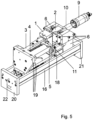
- FIG 4 the ultrasonic sealing device is shown in a side view.
- the anvil base 3 can be seen here in its installed position, in which it only appears as a flat rectangle. This is followed by the anvil 1 with the anvil blade 13.
- the sonotrode 2 is arranged opposite the anvil blade 13, with the welding of material webs taking place in the very small gap that is not visible in the illustration.
- the sonotrode 2 is fastened in a sonotrode holder 6, which in turn is fastened to a base plate 16.
- the second part of the stop 8 is fastened to the sonotrode holder 6, which is in contact with the adjustable part of the stop 7, which is fastened in the anvil 1.
- the position set on the adjustable part 7 directly influences the distance between the anvil blade 13 and the sonotrode 2.
- the sonotrode 2 is connected to a booster 10, the connection point being hidden by the sonotrode holder 6 in the figure.
- the booster 10 is in turn connected to the converter 9.
- a linear guide 17 is attached to the base plate 16, with which the anvil 1, the anvil substructure 3 and an anvil carriage 19 can be moved.
- the anvil carriage 19 is connected to a pneumatic cylinder 18, which makes it possible to remove the anvil blade 13 from the sonotrode 2. The welding gap is thereby opened wide.
- FIG 5 A perspective view of the ultrasonic sealing device is shown. Essentially the same elements as in the Figure 4 can be seen. However, the sonotrode holder 6 can be seen in more detail. A centering pin 22 can be seen in the end plate 20, which facilitates the precise positioning of the ultrasonic sealing device when installing it in a machine.
- a further stop can be provided for the rough positioning of the anvil.
- This further stop can be implemented in the linear unit.
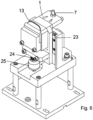
- FIG. 6 an alternative embodiment is shown.
- the anvil is not held by means of a solid-state joint, but rather by a linear unit 23.
- the spring element 24 ensures the passive mobility of the anvil 13.
- a load cell 25 is provided for measuring the force, although this can be dispensed with in some cases.
- a third embodiment is shown in a side view and in a top view.
- the sonotrode 2 is held by the sonotrode holder 6 and is connected to the converter 9 via the amplitude transformer 10.
- the entire sonotrode holder 6 can be moved for adjustment on the one hand linearly in the direction of the counter tool 13 and on the other hand around the swivel axis 32, which is in Figure 7
- the counter tool 13, which can be pivoted about the pivot axis 33, as shown in Figure 8 is preloaded into a predetermined position by means of the spring 24.
- the spring preload is achieved by means of the spindle nut 26, which can be moved linearly by turning the handwheel 27. With the help of the load cell 25, the The force applied to the material web can be measured.
- the counter tool 13 can be moved towards or away from the sonotrode 2 using a linear drive.
- the linear drive consists of a coarse drive 34 and a fine drive 35.
- the fine drive 35 can be adjusted using the micrometer screw 31 and fixed using the clamping screw 30.
- the distance sensor 29 is used to detect the position of the counter tool 13.
Landscapes
- Engineering & Computer Science (AREA)
- Mechanical Engineering (AREA)
- Physics & Mathematics (AREA)
- Thermal Sciences (AREA)
- Fluid Mechanics (AREA)
- Lining Or Joining Of Plastics Or The Like (AREA)
- Package Closures (AREA)
- Pressure Welding/Diffusion-Bonding (AREA)
Description
- Diese Erfindung betrifft ein Verfahren zur Ultraschallversiegelung gemäß Oberbegriff von Anspruch 1. Im allgemeinen ist der Amboss relativ zur Sonotrode bewegbar, so dass die Materialbahnen, wie z. B. Folienbahnen, leicht zwischen die Sonotrode und den Amboss gebracht werden können, die dann zum Verschweißen die Ultraschallschwingungen überlagert von einer Schweißkraft auf die Materialbahnen aufbringen. Grundsätzlich ist das Ultraschallsiegeln, bei dem 2 oder mehr Materialbahnen miteinander verschweißt werden, vom Ultraschallschneiden, bei dem die Materialbahnen mittels Ultraschall durchtrennt werden, zu unterscheiden.
- Beispielsweise werden die genannten Ultraschallsiegelvorrichtungen bei Schlauchbeutelverpackungsmaschinen zur Versiegelung der Kopf- und/oder Längsnähte eingesetzt.
- Die Dicke der jeweiligen Materialbahnen liegt häufig deutlich unter 0,1 mm. Änderungen der Prozessparameter oder Abweichungen der Materialeigenschaften oder der Schweißgeschwindigkeit haben daher einen starken Einfluss auf das Siegelergebnis. Die Beherrschung dieser Parameter zur Sicherstellung eines konstant guten Siegelergebnisses ist umso wichtiger, je dünner die Folien sind.
- Bei dünnen Folien findet der Siegelprozess in einem räumlich und funktional sehr begrenzten Bereich statt, wodurch schon geringere Änderungen der Prozesstemperatur, der Schweißkraft oder der Zustellung der Werkzeuge (Amboss und Sonotrode) zueinander das Siegelergebnis erheblich verändern kann.
- Nach dem Stand der Technik sind verschiedene Vorrichtungen und Vorgehensweisen bekannt, um die relevanten Prozessparameter und damit den Siegelprozess zu beherrschen (siehe beispielsweise
DE102006020429 ). - Eine Möglichkeit ist es, die Größe des Schweißspaltes konstant zu halten. Die Größe des Schweißspaltes wird insbesondere durch die thermische Ausdehnung der am Prozess beteiligten Bauteile beeinflusst. Die Wärme entsteht durch Verlustleistungen im Ultraschallerzeuger, Dämpfungsverlusten in den schwingenden Teilen und durch die Reibung im Prozess selbst. Zur Konstanthaltung des Schweißspaltes sind zwei verschiedene Verfahren gebräuchlich. Ein erstes ist die Konstantregelung der Leistungsabgabe des Generators. Dadurch wird der Wärmeeintrag in das System ebenfalls konstant, wodurch sich nach einer Einregelzeit konstante Prozessverhältnisse einstellen. Eine weitere Möglichkeit ist, den Abstand des Ambosses zur Sonotrode direkt zu erfassen und konstant zu regeln.
- Zur Einstellung des Schweißspaltes kommt dabei unter anderem ein Piezostellglied zum Einsatz. Eine weitere Möglichkeit, konstante Prozessbedingungen zu erreichen, stellt das Konstanthalten der Schweißkraft dar. Eine Möglichkeit der Realisierung ist es, die Siegelkraft zu erfassen und die Kraft über entsprechende Stellglieder konstant zu regeln.
- Diesen Lösungen ist gemeinsam, dass sie Regelungen verwenden, die teure Messtechnik, aufwendige und genaue Stellglieder und eine aufwendig zu konzipierende Regelung einschließlich Regelelektronik erfordern. Die auf diese Weise realisierten Regelkreise ermöglichen zwar die Prozessbeherrschung, beeinflussen jedoch die Bedienbarkeit, Verfügbarkeit und Komplexität der Ultraschallsiegelvorrichtungen negativ.
- Bei Schlauchbeutelverpackungsmaschinen werden häufig aneinander gesplicte Folien eingesetzt. Um die Folienbahnlänge zu verlängern, werden mehrere Folien aneinander befestigt. Dazu werden benachbarte Folienbahnen leicht überlappend aneinander gelegt und die Überlappstelle mit einem Klebestreifen versehen, so dass die beiden Folienbahnen zusammengehalten werden. Diese Splice-Verbindung kann innerhalb einer Folienrolle auftreten, da der Folienhersteller bereits mehrere Bahnen aneinandergefügt hat, oder kann manuell beim Rollenwechsel erzeugt werden. Durchläuft eine solche Splice-Verbindung den Spalt zwischen Sonotrode und Amboss, so erhöht sich die Materialbahndicke kurzzeitig abrupt auf mehr als das Doppelte. Solch abrupten Sprünge in der Materialbahndicke lassen sich mit den bekannten Ausführungsformen nur schwer handhaben.
- Bei der Ultraschallsiegelvorrichtung kann der Amboss der Materialbahn ausweichen, wenn der durch die Sonotrode auf die Materialbahn aufgebrachte Druck zu groß wird. Dehnt sich die Sonotrode beispielsweise während des Siegelvorgangs aus, so erhöht dies die Kraft, die die Sonotrodensiegelfläche auf die Materialbahn ausübt. Wird die Kraft so groß, dass kein zufriedenstellendes Schweißergebnis mehr zu erzielen ist, kann die Materialbahn durch die Beweglichkeit des Ambosses der Sonotrode ausweichen. Die Siegelkraft wird dabei durch den Gegenkrafterzeuger bestimmt.
- Beispielsweise kann der Gegenkrafterzeuger ein Federelement sein, welches den Amboss in Richtung der Referenzposition drückt. Alternativ dazu kann der Gegenkrafterzeuger auch einen Pneumatik- oder Hydraulikzylinder aufweisen.
- Besonders vorteilhaft ist es, wenn sich die Gegenkraft des Gegenkrafterzeugers einstellen lässt. Dadurch kann die Siegelkraft auf alle zu verarbeitenden Materialbahnen eingestellt werden.
- Diese Einstellbarkeit der Gegenkraft ermöglicht, die Schweißkraft einzustellen. Bei Federelementen kann die Gegenkraft dadurch eingestellt werden, dass die Vorspannung der Federelemente verändert wird. Dies ist möglich, indem durch Verstellen der Aufstandspunkte des Federelements dessen Länge verändert wird und damit die Vorspannung eingestellt wird. Diese Verstellung kann beispielsweise durch eine Stellschraube oder einen manuell betätigbaren oder automatisch, z. B. elektromotorisch, angetriebenen Stellantrieb realisiert werden. Da der Gegenkrafterzeuger auch ein Pneumatik- oder Hydraulikzylinder sein kann, kann die Schweißkraft in diesen Fällen durch Verändern eines im Betrieb konstanten Drucks in den Zylindern eingestellt werden.
- Um ein möglichst gutes Siegelergebnis zu erhalten, ist es nicht nur notwendig, die Siegelkraft zu begrenzen, sondern es muss ebenso sichergestellt werden, dass die Siegelkraft einen bestimmten minimalen Wert nicht unterschreitet. Dies kann beispielsweise durch entsprechende Einstellung der Gegenkraft erfolgen. Andererseits muss insbesondere bei der Verarbeitung von sehr dünnen Folien sichergestellt werden, dass sich Ambosssiegelfläche und Sonotrodensiegelfläche nicht zu sehr annähern um ein Durchtrennen der Materialbahn zu verhindern.
- Daher ist bei der Ultraschallsiegelvorrichtung ein Anschlagelement vorgesehen, welches derart angeordnet ist, dass es die Bewegung des Amboss in Richtung der Sonotrode begrenzt, so dass die Ambosssiegelfläche einen durch das Anschlagelement festgelegten Mindestabstand zur Sonotrodensiegelfläche einhält, wobei besonders bevorzugt der Mindestabstand einstellbar ist. Das Anschlagelement verhindert somit, dass sich die Ambosssiegelfläche weiter in Richtung der Sonotrodensiegelfläche bewegt, selbst wenn die Kraft des Gegenkrafterzeugers weiter erhöht wird. Dies hat auch den Vorteil, dass der Siegeldruck, der mit dem Gegenkrafterzeuger bereitgestellt werden kann, deutlich erhöht werden kann, ohne dass im Betrieb die Gefahr der Durchtrennung der Materialbahn besteht. Zudem lässt sich bei dieser Konfiguration leichter die von dem Gegenkrafterzeuger bereitgestellte Gegenkraft im wesentlichen konstant halten.
- So kann beispielsweise der Gegenkrafterzeuger derart eingestellt sein, dass der Amboss eine Kraft auf das Anschlagelement ausübt, wenn der Amboss den Mindestabstand zu der Sonotrode hat, d.h. wenn der Amboss am Anschlagelement an liegt. Wenn der Gegenkrafterzeuger ein oder mehrere Federelemente umfasst, so hängt die Schweißkraft in einem bestimmten Maße auch von der Materialbahnstärke bzw. auch von der Dämpfung und der Elastizität des zu verschweißenden Materialsab.
- Ein Federgelenk als Führung kann durch seine Federwirkung ebenfalls einen Teil des Gegenkrafterzeugers darstellen. Um eine geeignete Einstellbarkeit der Schweißkraft zu erreichen, müssen die Federraten des Federgelenkes und eines Federelements als einstellbarer Gegenkrafterzeuger aufeinander abgestimmt werden. Dies gilt entsprechend für Hydraulik- oder Pneumatikzylinder. Durch die Verwendung einer langen Feder, die um eine Vorspannstrecke zusammengedrückt wird, und in diesem Zustand an einem Anschlag anliegt, kann eine ebenso hohe Schweißkraft erreicht werden, wie durch die Verwendung einer kürzeren Feder mit einer höheren Federrate, die nur um eine geringere Vorspannstrecke vorgespannt ist. Der Vorteil der längeren Feder ist, dass Schwankungen der Materialbahndicke und damit Änderungen der Vorspannung zu geringeren Kraftänderungen führen, was letztlich in einem gleichmäßigeren Schweißprozess resultiert. Die Vorspannstrecke beträgt folglich vorteilhaft mindestens das Doppelte der zulässigen Maximalauslenkung des Ambosses. Wird ein Pneumatik-oder Hydraulikzylinder mit einem konstanten Druck beaufschlagt und stellt dies den Hauptanteil der Gegenkraft dar, so ist die Schweißkraft von der Dicke der Materialbahnstärkeweitgehend unabhängig. Die Federrate der Feder und die Masse des beweglichen Aufbaus beeinflusst außerdem die Resonanzfrequenz des Ambosses. Je härter die Feder ist, desto höher ist die Resonanzfrequenz. Die Resonanzfrequenz liegt vorteilhaft deutlich unter der Schwingfrequenz der Sonotrode.
- Die Einstellbarkeit des Anschlagelementes kann beispielsweise erreicht werden, indem ein Teil des Anschlagelementes durch eine Schraube, z. B. eine Stiftschraube, gebildet wird. Weiterhin ist es von Vorteil, wenn die Schraube als Messschraube am besten mit Feingewinde ausgebildet ist, so dass die gewünschte Einstellung leicht wieder aufgefunden werden kann. Diese kann sowohl auf der Seite der Sonotrode, als auch auf der Seite des Ambosses angeordnet sein. Das Gegenstück des Anschlagelementes ist vorzugsweise aus einem verschleißfesten Material hergestellt, beispielsweise aus Hartmetall, gehärtetem Stahl oder einem anderen Werkstoff mit hoher Festigkeit. Wichtig ist hierbei, dass der einstellbare Anschlag auf dem feststehenden oder beweglich (gefederten) Teil platziert wird.
- In einer weiteren Ausführungsform sind sowohl Sonotrode als auch Amboss an einer Basiskonsole befestigt, wobei der Amboss über eine Linearführung zur Sonotrode hin oder von dieser wegbewegt werden kann. Dadurch kann ein flexibel einsetzbares Ultraschallsiegelmodul bereitgestellt werden, welches in den unterschiedlichsten Maschinen eingesetzt werden kann. Dadurch, dass der Amboss relativ zur Sonotrode bewegt werden kann, wird die Zugänglichkeit des Moduls bei Einstell- oder Wartungsarbeiten gewährleistet und die Folienbahn kann leicht zwischen Sonotrode und Amboss eingeführt werden. Zudem kann die Linearführung verwendet werden, um den Arbeitspunkt (Spaltgröße) grob einzustellen. Die exakte Einstellung des Arbeitspunktes erfolgt dann über den Gegenkrafterzeuger.
- Ebenso kann diese separate Linearführung alleine oder in Kombination mit dem Gegenkrafterzeuger verwendet werden um definierte Mehrlagigkeiten der Materialbahn zu kompensieren. Vorteilhaft ist hierbei, dass die Mehrlagigkeit durch das komplette Siegelmodul kompensiert wird und die nicht verschweißten Fehlstellen auf ein Minimum reduziert werden.
- Beispielsweise kann der Amboss einen Ambossunterbau und einen über ein Gelenk mit diesem verbundenen Arbeitsabschnitt, auf dem die Ambosssiegelfläche angeordnet ist, aufweisen, wobei das Gelenk vorzugsweise ein Festkörpergelenk ist.
- Vorteil einer solchen Ultraschallsiegelvorrichtung ist, dass der Amboss aufgrund seines einfachen Aufbaus und seiner Lagerung mit einem Federgelenk eine sehr geringe Masse haben kann. Dadurch kann die Resonanzfrequenz trotz geringer Federsteifigkeiten erhöht werden, was ein schnelles Reagieren auf Änderungen der Materialdicke und der Eigenschaften der zu verschweißenden Bahnen ermöglicht. Selbstverständlich sollte die Resonanzfrequenz deutlich unter der Schwingungsfrequenz der Sonotrode liegen. Zudem ist durch ein Federgelenk eine spielfreie Führung realisiert, die eine sehr gleichmäßige Naht ermöglicht. Außerdem wird dadurch die Konstanthaltung der Prozessparameter unterstützt. Ein weiterer Vorteil eines Federgelenkes ist, dass es reibungsfrei arbeitet und dadurch keine Hystereseeffekte oder Stick-Slip-Effekte auftreten. In einer weiteren Ausführungsform ist das Federgelenk als Festkörpergelenk ausgeführt.
- Dadurch kann der Amboss aus einem Stück durch Drahterosion hergestellt werden, was den Fertigungsaufwand im Vergleich zu anderen Lösungen drastisch verringert. Zudem haben Festkörpergelenke bessere Eigenschaften als Federgelenke, die aus mehreren Stücken, z. B. mit einem Stück Federblech als Federelement hergestellt werden. Dies ist vor allem durch die Homogenität des Materials und Reibung in den Verbindungsstellen begründet. Durch die dauernde Federbewegung können sich verschraubte Teile zueinander bewegen und erfordern zusätzliche Sicherungsmaßnahmen, um eine dauerhafte Führungsgenauigkeit zu gewährleisten.
- Der bewegliche Ambossaufbau ist auf einer Lineareinheit angeordnet, welche vorzugsweise sehr genau geführt ist. Wichtig ist hierbei eine lange, möglichst genaue Führungseinheit, welche sehr wenig Reibungsverluste und somit wenig undefinierte Kraftzustände zulässt. Diese Führungseinheit kann ebenso mit einem Gegenkrafterzeuger ausgerüstet sein. Des weiteren kann die jeweilige Schweißkraft über einen zusätzlich adaptierbaren Kraftaufnehmer ermittelt werden. Dieser wird in Reihe, also im direkten Kraftfluss zur eingeleiteten Schweißkraft implementiert.
- Erfindungsgemäß wird ein Verfahren zur Ultraschallversiegelung gemäß Anspruch 1 vorgeschlagen.
- Dabei wird erfindungsgemäß das Anschlagselement derart eingestellt, dass der Mindestabstand zwischen Ambosssiegelfläche und Sonotrodensiegelfläche kleiner als die Dicke der zu siegelnden Folien, nämlich zwischen 0,25 und 0,75 der Dicke der zu siegelnden Folien und vorzugsweise zwischen 0,4 und 0,6 der Dicke der zu siegelnden Folien ist. Dabei wird unter der Dicke der zu versiegelnden Folie die Gesamtdicke der zu versiegelnden Materialbahnen verstanden. Wird beispielsweise eine Folie mit einer Dicke von 0,3 mm zweilagig gesiegelt beträgt die Dicke der zu siegelnden Folien 0,6 mm.
- Weiterhin ist in einer bevorzugten Ausführungsform vorgesehen, dass der Gegenkrafterzeuger derart eingestellt wird, dass der Amboss eine voreingestellte Siegelkraft auf das Anschlagelement aufbringt.
- Um die Veränderung des Siegelspaltes aufgrund der Erwärmung der Sonotrode zu minimieren kann vorgesehen sein, dass während einer ersten Siegelperiode eine größere Ultraschallleistung für das Siegeln verwendet wird als in einer zweiten Siegelperiode, die nach der ersten Siegelperiode liegt.
- Durch diese Maßnahme wird während der ersten Siegelperiode mehr Energie in das System eingebracht. Während dieser Siegelperiode kommt es daher zu einer schnellen Erwärmung des Werkzeuges. Die erste Siegelperiode ist so bemessen, dass die Werkzeugtemperatur auf die gewünschte Arbeitstemperatur erhöht wird.
- Die Temperatur der Siegelwerkzeuge beeinflusst die Ultraschallsiegelung. Durch den Kontakt zwischen Sonotrode und/oder Gegenwerkzeug mit der zu bearbeitenden Materialbahn wird Wärmeenergie in diese übertragen. Je wärmer Sonotrode und/oder Gegenwerkzeug sind, umso weniger Ultraschallenergie ist für den Schweißvorgang notwendig.
- Weiterhin kann die Temperatur der Sonotrodensiegelfläche erfasst werden und vorzugsweise die Ultraschallleistung in Abhängigkeit von der Temperatur der Sonotrodensiegelfläche gewählt werden.
- Alternativ oder in Kombination zur Einstellung der Ultraschallleistung kann die Temperatur der Sonotrode auf eine Arbeitstemperatur geregelt werden.
- Beispielsweise kann die Sonotrode und/oder der Amboss vordem Siegelvorgang aufgewärmt werden. Durch die Aufwärmung zu Beginn der Produktion wird vermieden, dass die ersten Schweißnähte fehlerhaft sind, weil die richtige Prozesstemperatur noch nicht erreicht ist. Diese Vorwärmtemperatur entspricht vorteilhaft der Temperatur, die während des Schweißprozesses optimal ist.
- In einer weiteren Ausführungsform wird die Temperatur der Sonotrode und/oder optional vorhandene Zwischenteile zwischen Sonotrode und Ultraschallerzeugungseinheit und/oder des Ambosses durch Änderungen der Prozessparameter des Ultraschallschwingers wie z. B. Amplitude und/oder Kraft oder durch die Temperatur von Temperierungsmedien im Wesentlichen konstant gehalten, wodurch Auswirkungen von Variationen der Schweißgeschwindigkeit, der Umgebungstemperatur, von Materialungleichmäßigkeiten oder von anderen Parametern, die die Temperatur beeinflussen, verringert werden.
- Durch die genannten Maßnahmen kann die Temperatur an der Schweißstelle beeinflusst werden. Durch Rückkopplung geeigneter Prozessparameter, wie z. B. einem Temperatursignal von der Schweißstelle, der Leistungsabgabe der Ultraschallerzeugungseinheit oder der Schweißgeschwindigkeit können die genannten Effekte als Stellglieder in einem Regelkreis eingebunden werden. Auf diese Weise kann die Temperatur über einen einfachen oder auch komplexen Regelkreis konstant gehalten werden, wodurch Variationen von Schweißgeschwindigkeit, Umgebungstemperatur, Materialungleichmäßigkeiten oder anderen Parametern, die die Temperatur beeinflussen, ausgeregelt werden.
- In einer weiteren Ausführungsform ist das Anschlagselement am Arbeitselement befestigt und weist im Wesentlichen den gleichen Abstand von dem Federgelenk wie die Ambosssiegelfläche auf.
- Dadurch ist der Hebelarm für das Anschlagselement und für die Ambosssiegelfläche gleich, so dass eine Verstellstrecke die gleiche Änderung in der Größe des Prozessspaltes bewirkt. So kann beispielsweise eine Mikrometerschraube das Anschlagselement darstellen und deren Skala als Maß für die Spalteinstellung genutzt werden. Die Handhabung des Anschlagselements wird dadurch vereinfacht.
- In einer weiteren Ausführungsform ist die Gegenkraft durch den Gegenkrafterzeuger messbar.
- Da diese Vorspannung im Wesentlichen der Schweißkraft entspricht, kann durch eine solche Messung die Schweißkraft ermittelt werden. Dies kann zur Prozessüberwachung nützlich sein, z. B. kann die Schweißkraft auf einen Sollwert geregelt werden. Die Messung kann beispielsweise durch eine Kraftmessdose erfolgen, über die der Kraftfluss zum Amboss geleitet wird. Bei einem hydraulischen oder pneumatischen Gegenkrafterzeuger kann alternativ der Druck gemessen werden, der die Gegenkraft erzeugt.
- In einer weiteren Ausführungsform dient die gemessene Gegenkraft als Referenzparameter für unterschiedliche Folienstrukturen beim Einrichten des Systems.
- Zum Verschweißen von verschiedenen Materialbahnen kann eine unterschiedliche Schweißkraft erforderlich sein. Um diese schnell einstellen zu können, ist es zweckmäßig, entsprechende Einstellwerte vorzuhalten. Diese können zuvor durch die Messung der Vorspannung erhalten worden sein.
- In einer weiteren Ausführungsform ist die Bewegungsmöglichkeit des Ambosses und damit auch des Federgelenks quer zu seiner Hauptfederrichtung durch einen oder mehrere Seitenanschläge begrenzt.
- Auf diese Weise wird das Federgelenk vor Kräften geschützt, die es möglicherweise quer zur seiner Hauptfederrichtung zerstören könnten.
- In einer weiteren Ausführungsform ist der Ambossunterbau gegenüber dem Element, an dem er befestigt ist, mit einer Linearführung beweglich gelagert.
- In einer weiteren Ausführungsform wird der Amboss von Temperierflüssigkeit durchflossen, um diesen zu temperieren.
- Dies kann dazu dienen, die Temperatur während des Schweißprozesses konstant zu halten, oder um den Amboss vor Aufnahme der Produktion vorzuwärmen.
- In einer weiteren Ausführung ist ein Temperiersystem in unmittelbarer Nähe der Schweißstelle des Ambosses und/oder einer Sonotrode angeordnet.
- Das Temperiersystem kann beispielsweise eine elektrische Heizung sein. Diese kann dazu dienen, die Prozesstemperatur konstant zu halten oder Sonotrode und/oder Amboss vor Aufnahme einer Produktion vorzuwärmen.
- In einer weiteren Ausführung wird die Temperatur der Schweißstelle des Ambosses und/oder die Temperatur der Sonotrodensiegelfläche erfasst.
- Diese Temperaturen stellen ein Maß für die Schweißtemperatur dar. Die Temperaturen können beispielsweise durch einen Regelkreis konstant gehalten werden.
- In einer weiteren Ausführungsform wird der Amboss und/oder die Sonotrode zur Temperierung mit Luft mit konstanter Temperatur angeblasen.
- Dies kann dazu dienen, die Prozesstemperatur konstant zu halten und/oder Amboss und Sonotrode vor der Aufnahme einer Produktion vorzuwärmen.
- In einer weiteren Ausführungsform wird die Temperatur der Luft geregelt, so dass thermische Veränderungen an der Schweißstelle ausgeregelt werden.
- In einer weiteren Ausführungsform ist die Sonotrode im Wesentlichen aus Titan, Aluminium oder Stahl gefertigt.
- Mit einer solchen Sonotrode kann Wärme, die beim Schweißprozess entsteht, schnell aus der Schweißstelle abgeführt werden. Die dient einer schnelleren Reaktion des Systems auf thermische Veränderungen an der Schweißstelle.
- In einer weiteren besonders bevorzugten Ausführungsform erfolgt die Befestigung der Ultraschallschwingeinheit direkt an der Sonotrode. Dadurch reduziert sich die durch Längenänderungen der Sonotrode aufgrund von Temperaturschwankungen hervorgerufene Veränderung der Spaltbreite.
- Weitere Vorteile, Merkmale und Anwendungsmöglichkeiten der Erfindung ergeben sich sowohl aus der folgenden Beschreibung bevorzugter Ausführungsformen der Ultraschallsiegelvorrichtung, die erfindungsgemäß verwendet wird, als auch aus den dazugehörigen Figuren. Es zeigen:
-
Figur 1 eine perspektivische Ansicht des Ambosses und des Ambossunterbaus, -
Figur 2 eine weitere perspektivische Ansicht des Ambosses und des Ambossunterbaus, -
Figur 3 eine weitere perspektivische Ansicht des Ambosses und des Ambossunterbaus, -
Figur 4 eine Seitenansicht der Ultraschallsiegelvorrichtung im Zusammenbau, -
Figur 5 eine perspektivische Ansicht der Ultraschallsiegelvorrichtung im Zusammenbau, -
Figur 6 eine perspektivische Ansicht einer zweiten Ausführungsform eines Ambosses und des Ambossunterbaus, -
Figur 7 eine Seitenansicht einer dritten Ausführungsform und -
Figur 8 eine Ansicht von oben auf die dritte Ausführungsform gemäßFigur 7 . - In
Figur 1 ist der Amboss 1 und der Ambossunterbau 3 mit ihren Anbauteilen gezeigt. Der Ambossunterbau 3 geht über das Federgelenk 5 einstückig in den balkenförmigen Arbeitsabschnitt 12 über, an dem die Ambosssiegelfläche angeordnet ist. Die Ambosssiegelfläche besteht hier aus einer Ambossklinge 13. An dem balkenförmigen Teil 12 ist außerdem eine Stellschraube 11 zur Einstellung der Federvorspannung des Federelementes 4 vorgesehen. In dem Amboss 1 ist außerdem ein einstellbarer Teil des Anschlags 7 vorgesehen, der mit einem zweiten Teil des Anschlags 8 zusammenwirkt, der inFigur 1 nicht dargestellt ist. Seitlich neben dem Amboss 1 ist einer der zwei Seitenanschläge 14 zu sehen, der an dem Ambossunterbau 3 befestigt ist. Dieser begrenzt die Bewegungsmöglichkeiten des Amboss in Richtung des Seitenanschlags 14, so dass das Federgelenk 5 durch Stellkräfte an der Einstellschraube 11 oder durch Seitenkräfte, die durch Fehler beim Schweißprozess entstehen können, auftreten. Der Unterbau 3 weist eine Aussparung auf, in der ein Federelement 4 eingesetzt ist. Dieses stellt eine Vorspannung zwischen dem balkenförmigen Arbeitsabschnitt 12 des Ambosses 1 und dem Ambossunterbau 3 her. Das Federelement 4 bildet die Gegendruckeinrichtung 4, 5, die durch ihre Federwirkung den Kräften von der Sonotrode 2 entgegen wirkt. -
Figur 2 zeigt im Wesentlichen dieselben Elemente des Ambosses wieFigur 1 . Durch die andere Perspektive ist jedoch der andere Seitenanschlag 14 zu sehen. - In
Figur 3 ist ebenfalls der Ambossunterbau 3 und der Amboss 1 mit Anbauteilen zu sehen. In dieser Perspektive sind außerdem die Kontermutter des Anschlagsteils 7 und zwei Passfedern 15, die parallel zueinander an der Endfläche des Ambossunterbaus 3 angeordnet sind, zu sehen. Sie dienen einer ausgerichteten Montage der Ultraschallsiegelvorrichtung in einer übergeordneten Einheit, beispielsweise einer Schlauchbeutelverpackungsmaschine bzw. einer linear angeordneten Verstelleinheit. - In
Figur 4 ist die Ultraschallsiegelvorrichtung in einer Seitenansicht dargestellt. Der Ambossunterbau 3 ist hier in seiner Einbauposition zu sehen, in der er nur als flaches Rechteck erscheint. Daran schließt sich der Amboss 1 mit der Ambossklinge 13 an. Der Ambossklinge 13 gegenüber ist die Sonotrode 2 angeordnet, wobei in dem sehr kleinen, in der Abbildung nicht sichtbaren Zwischenraum die Verschweißung von Materialbahnen stattfindet. Die Sonotrode 2 ist in einem Sonotrodenhalter 6 befestigt, der wiederum an einer Basisplatte 16 befestigt ist. An dem Sonotrodenhalter 6 ist der zweite Teil des Anschlags 8 befestigt, der mit dem einstellbaren Teil des Anschlags 7, der in dem Amboss 1 befestigt ist, in Kontakt steht. Die an dem einstellbaren Teil 7 eingestellte Position beeinflusst unmittelbar den Abstand zwischen der Ambossklinge 13 und der Sonotrode 2. Die Sonotrode 2 ist mit einem Booster 10 verbunden, wobei die Verbindungsstelle von dem Sonotrodenhalter 6 in der Figur verdeckt ist. Der Booster 10 ist wiederum mit dem Konverter 9 verbunden. An der Basisplatte 16 ist eine Linearführung 17 befestigt, mit der der Amboss 1, der Ambossunterbau 3 und ein Ambossschlitten 19 verfahren werden können. Der Ambossschlitten 19 ist mit einem Pneumatikzylinder 18 verbunden, der es ermöglicht, die Ambossklinge 13 von der Sonotrode 2 zu entfernen. Der Schweißspalt wird dadurch weit geöffnet. Bei dem Pneumatikzylinder 18 handelt es sich vorzugsweise um einen doppelt wirkenden Pneumatikzylinder. An den Enden der Grundplatte 16 sind Abschlussplatten 20 und 21 angebracht, die zur Befestigung der Ultraschallsiegelvorrichtung z. B. in einer Maschine dienen. - In
Figur 5 ist eine perspektivische Ansicht der Ultraschallsiegelvorrichtung dargestellt. Es sind im Wesentlichen dieselben Elemente wie in derFigur 4 zu sehen. Die Sonotrodenhalterung 6 ist jedoch detaillierter erkennbar. In der Endplatte 20 ist ein Zentrierstift 22 zu sehen, der die genaue Positionierung der Ultraschallsiegelvorrichtung beim Einbauen in eine Maschine erleichtert. - Des weiteren kann ein weiterer Anschlag zur groben Positionierung des Ambosses vorgesehen sein. Dieser weitere Anschlag kann in der Lineareinheit verwirklicht sein.
- In
Figur 6 ist eine alternative Ausführungsform dargestellt. Im Gegensatz zu der vorherigen Ausführungsform wird hier der Amboss nicht mittels eines Festkörpergelenks, sondern über eine Lineareinheit 23 gehalten. Das Federelement 24 stellt die passive Beweglichkeit des Ambosses 13 sicher. Zur Messung der Kraft ist eine Kraftmessdose 25 vorgesehen, auf die in manchen Fällen verzichtet werden kann. - In den
Figuren 7 und 8 ist eine dritte Ausführungsform in einer Seitenansicht und in einer Ansicht von oben dargestellt. - Die Sonotrode 2 wird über den Sonotrodenhalter 6 gehalten und ist über den Amplitudentransformator 10 mit dem Konverter 9 verbunden. Der gesamte Sonotrodenhalter 6 lässt sich zur Justage einerseits linear in Richtung des Gegenwerkzeuges 13 bewegen und andererseits um die Schwenkachse 32, die in
Figur 7 dargestellt ist, verschwenken. Das Gegenwerkzeug 13, welches um die Schwenkachse 33 verschwenkt werden kann, wie inFigur 8 angedeutet ist, wird mit Hilfe der Feder 24 in eine vorbestimmte Position vorgespannt. Die Federvorspannung erfolgt mit Hilfe der Spindelmutter 26, welche durch Drehung am Handrad 27 linear bewegt werden kann. Mit Hilfe der Kraftmessdose 25 kann die auf die Materialbahn aufgebrachte Kraft gemessen werden. - Das Gegenwerkzeug 13 kann mit Hilfe eines Linearantriebes auf die Sonotrode 2 zu oder von dieser weg bewegt werden. Der Linearantrieb besteht in der gezeigten Ausführungsform aus einem Grobantrieb 34 und einem Feinantrieb 35. Der Feinantrieb 35 kann mit Hilfe der Mikrometerschraube 31 eingestellt und mit Hilfe der Klemmschraube 30 fixiert werden. Den Abstandssensor 29 dient zur Erfassung der Position des Gegenwerkzeuges 13.
-
- 1
- Amboss
- 2
- Sonotrode
- 3
- Ambossunterbau
- 4
- Federelement
- 5
- Federgelenk
- 4, 5
- Gegendruckeinrichtung
- 6
- Sonotrodenhalter
- 7
- Anschlag
- 8
- Anschlag
- 9
- Konverter
- 10
- Booster, Amplitudentransformator
- 11
- Stellschraube
- 12
- balkenförmiger Arbeitsabschnitt
- 13
- Ambossklinge
- 14
- Seitenanschlag
- 15
- Passfedern
- 16
- Basisplatte
- 17
- Linearführung
- 18
- Pneumatikzylinder
- 19
- Ambossschlitten
- 20, 21
- Abschlussplatten
- 22
- Zentrierstift
- 23
- Lineareinheit
- 24
- Federelement
- 25
- Kraftmessdose
- 26
- Spindelmutter
- 27
- Handrad
- 29
- Abstandssensor
- 30
- Klemmschraube
- 31
- Mikrometerschraube
- 32, 33
- Schwenkachse
- 34
- Grobantrieb
- 35
- Feinantrieb
Claims (6)
- Verfahren zur Ultraschallversiegelung, bei welchem eine Ultraschallsiegelvorrichtung zum Versiegeln von Materialbahnen, wie z.B. Folien, mit einem Amboss (1) mit einer Ambosssiegelfläche und einer Sonotrode (2) mit einer Sonotrodensiegelfläche, wobei der Amboss (1) relativ zur Sonotrode (2) beweglich ist, wobei ein Gegenkrafterzeuger (4) vorgesehen ist, welcher eine Gegenkraft auf den Amboss (1) in Richtung der Sonotrode (2) ausübt, wenn der Amboss (1) aus einer Referenzposition von der Sonotrode (2) wegbewegt wird, wobei der Amboss (1) auf einer beweglichen Lineareinheit (23) angeordnet ist und ein Anschlagelement (7) vorgesehen ist, welches derart angeordnet ist, dass es die Bewegung des Amboss (1) in Richtung der Sonotrode (2) begrenzt, so dass die Ambosssiegelfläche einen durch das Anschlagelement (7) festgelegten Mindestabstand zur Sonotrodensiegelfläche einhält, wobei der Gegenkrafterzeuger (4, 5) derart eingestellt ist, dass der Amboss (1) eine Kraft auf das Anschlagelement (7, 8) ausübt, wenn der Amboss (1) den Mindestabstand zu der Sonotrode (2) hat, verwendet wird, dadurch gekennzeichnet, dass das Anschlagselement (7) derart eingestellt wird, dass der Mindestabstand zwischen Ambosssiegelfläche und Sonotrodensiegelfläche zwischen 0,25 und 0,75 der Dicke der zu siegelnden Folien ist.
- Verfahren nach Anspruch 1, dadurch gekennzeichnet, dass der Gegenkrafterzeuger derart eingestellt wird, dass der Amboss (1) eine voreingestellte Siegelkraft auf das Anschlagelement (7) aufbringt.
- Verfahren nach einem der Ansprüche 1 bis 2, dadurch gekennzeichnet, dass während einer ersten Siegelperiode eine größere Ultraschallleistung für das Siegeln verwendet wird als in einer zweiten Siegelperiode, die nach der ersten Siegelperiode liegt.
- Verfahren nach einem der Ansprüche 1 bis 3, dadurch gekennzeichnet, dass die Temperatur der Sonotrodensiegelfläche erfasst wird und vorzugsweise die Ultraschallleistung in Abhängigkeit von der Temperatur der Sonotrodensiegelfläche gewählt wird.
- Verfahren nach Anspruch 4, dadurch gekennzeichnet, dass die Temperatur der Sonotrode (2) und/oder des Ambosses (1) auf eine Arbeitstemperatur geregelt wird.
- Verfahren nach einem der Ansprüche 1 bis 5, dadurch gekennzeichnet, dass die Gegenkraft des Ambosses (1) erfasst und auf einen vorbestimmten Wert geregelt wird.
Applications Claiming Priority (2)
| Application Number | Priority Date | Filing Date | Title |
|---|---|---|---|
| DE102009002675A DE102009002675A1 (de) | 2009-04-27 | 2009-04-27 | Ultraschallsiegelvorrichtung und Verfahren zum Versiegeln von Materialbahnen |
| PCT/EP2010/055563 WO2010125030A1 (de) | 2009-04-27 | 2010-04-26 | Ultraschallsiegelvorrichtung und verfahren zum versiegeln von materialbahnen |
Publications (3)
| Publication Number | Publication Date |
|---|---|
| EP2424724A1 EP2424724A1 (de) | 2012-03-07 |
| EP2424724B1 EP2424724B1 (de) | 2019-08-28 |
| EP2424724B2 true EP2424724B2 (de) | 2024-12-18 |
Family
ID=42330998
Family Applications (1)
| Application Number | Title | Priority Date | Filing Date |
|---|---|---|---|
| EP10719927.5A Active EP2424724B2 (de) | 2009-04-27 | 2010-04-26 | Ultraschallsiegelvorrichtung und verfahren zum versiegeln von materialbahnen |
Country Status (5)
| Country | Link |
|---|---|
| US (1) | US8557071B2 (de) |
| EP (1) | EP2424724B2 (de) |
| CN (1) | CN102421584B (de) |
| DE (1) | DE102009002675A1 (de) |
| WO (1) | WO2010125030A1 (de) |
Families Citing this family (46)
| Publication number | Priority date | Publication date | Assignee | Title |
|---|---|---|---|---|
| ES1075973Y (es) * | 2011-05-12 | 2012-04-13 | Eficiencia Y Tecnologia S A | Dispositivo de soldadura longitudinal en continuo para maquinas envasadoras |
| CA2831272A1 (en) * | 2012-12-13 | 2014-06-13 | Rinco Ultrasonics Usa Inc. | Retrofit of a form-fill-seal machine heat station with an advanced ultrasonic welding kit |
| DE102013100474A1 (de) * | 2013-01-17 | 2014-07-17 | Herrmann Ultraschalltechnik Gmbh & Co. Kg | Ultraschallschweißvorrichtung mit schwingungsentkoppeltem Gegenwerkzeug |
| FR3003645B1 (fr) * | 2013-03-19 | 2015-03-06 | Renault Sa | Procede de controle de cordons de soudure par ultrasons |
| CN104129537A (zh) * | 2013-05-03 | 2014-11-05 | 纷美包装(山东)有限公司 | 料卷接头检测装置 |
| JP2016528738A (ja) * | 2013-08-21 | 2016-09-15 | ジーティーエイティー・コーポレーション | 金属片を太陽電池へ連結するためのアクティブはんだの使用 |
| US9550323B2 (en) * | 2013-09-06 | 2017-01-24 | GM Global Technology Operations LLC | Systems and methods for adaptive process control using a target kinematics profile in welding together multiple polymeric workpieces |
| DE102014112061B3 (de) * | 2014-08-22 | 2016-01-14 | Ms Spaichingen Gmbh | Amboss |
| US10959456B2 (en) | 2014-09-12 | 2021-03-30 | R.J. Reynolds Tobacco Company | Nonwoven pouch comprising heat sealable binder fiber |
| DE102014015958A1 (de) | 2014-10-31 | 2016-05-04 | Sig Technology Ag | Vorrichtung, insbesondere zum Verschließen eines Kopfbereichs eines Nahrungsmittel-behälters, aus einem Laminat mit geschältem und umgeschlagenen Randbereich |
| US20160157515A1 (en) | 2014-12-05 | 2016-06-09 | R.J. Reynolds Tobacco Company | Smokeless tobacco pouch |
| DE102015009373B4 (de) | 2015-07-24 | 2018-11-29 | Kunststoff-Zentrum In Leipzig Gemeinnützige Gmbh | Verfahren und Vorrichtung zur Regelung der Temperatur von in Resonanz schwingenden Ultraschallsonotroden |
| DE102015121354A1 (de) * | 2015-12-08 | 2017-06-08 | Ms Ultraschall Technologie Gmbh | Ständermaschine |
| DE102016112757A1 (de) | 2016-07-12 | 2018-01-18 | Herrmann Ultraschalltechnik Gmbh & Co. Kg | Ultraschallbearbeitungsvorrichtung |
| DE202016009138U1 (de) | 2016-07-12 | 2022-10-11 | Herrmann Ultraschalltechnik Gmbh & Co. Kg | Ultraschallbearbeitungsvorrichtung |
| DE202016009202U1 (de) | 2016-07-12 | 2023-11-27 | Herrmann Ultraschalltechnik Gmbh & Co. Kg | Ultraschallbearbeitungsvorrichtung |
| DE102017104615A1 (de) * | 2017-03-06 | 2018-09-06 | Auto-Kabel Management Gmbh | Ultraschallschweißvorrichtung und Verfahren zum Ultraschallschweißen |
| CZ308525B6 (cs) * | 2017-05-04 | 2020-10-29 | Velteko S.R.O. | Výměnná ultrazvuková svařovací čelist pro svařování podélných výztužných hran na obalové fólii v balicím stroji a způsob její výměny |
| US10746703B2 (en) | 2018-11-13 | 2020-08-18 | Dukane Ias, Llc | Automated ultrasonic press systems and methods for welding physically variant components |
| US20210169138A1 (en) | 2019-12-09 | 2021-06-10 | Nicoventures Trading Limited | Fibrous fleece material |
| CA3159451A1 (en) | 2019-12-09 | 2021-06-17 | Savannah JOHNSON | Pouched products with heat sealable binder |
| BR112022010981A2 (pt) | 2019-12-09 | 2022-08-23 | Nicoventures Trading Ltd | Produto oral em uma bolsa porosa compreendendo um material de velo |
| EP4072348A2 (de) | 2019-12-09 | 2022-10-19 | Nicoventures Trading Limited | Stimulus-responsiver beutel |
| EP4072347B1 (de) | 2019-12-09 | 2025-02-12 | Nicoventures Trading Limited | Vlies für orales produkt mit lösbarer komponente |
| PH12022551272A1 (en) | 2019-12-09 | 2023-11-29 | Nicoventures Trading Ltd | Oral product with dissolvable component |
| DE102020130325A1 (de) * | 2020-11-17 | 2022-05-19 | Herrmann Ultraschalltechnik Gmbh & Co. Kg | Verfahren zum Betreiben einer Ultraschallschweißmaschine |
| CN112938040B (zh) * | 2021-02-05 | 2022-08-02 | 重庆雄达铨瑛电子有限公司 | 一种铝箔封口装置 |
| US11511900B2 (en) * | 2021-03-18 | 2022-11-29 | Osgood Industries, Llc | Adjustable frame mount for process unit |
| US20220346436A1 (en) | 2021-04-22 | 2022-11-03 | Nicoventures Trading Limited | Orally dissolving films |
| DE102021117169A1 (de) * | 2021-07-02 | 2023-01-05 | Herrmann Ultraschalltechnik Gmbh & Co. Kg | Ultraschallschweißanlage sowie Verfahren zur schweißenden Bearbeitung von Materialien |
| US11407182B1 (en) * | 2021-08-11 | 2022-08-09 | Dukane Ias, Llc | Depth control of seal line penetration for rotary ultrasonic horn/anvil welding without mechanical stop |
| WO2023084499A1 (en) | 2021-11-15 | 2023-05-19 | Nicoventures Trading Limited | Products with enhanced sensory characteristics |
| JP2024546045A (ja) | 2021-11-15 | 2024-12-17 | ニコベンチャーズ トレーディング リミテッド | ニコチン-ポリマー複合体を有する口腔用製品 |
| CA3247270A1 (en) | 2022-04-06 | 2023-10-12 | Nicoventures Trading Limited | PRODUCTS IN BAGS WITH HEAT-SEALABLE BINDER |
| WO2024079722A1 (en) | 2022-10-14 | 2024-04-18 | Nicoventures Trading Limited | Capsule-containing pouched products |
| WO2024089588A1 (en) | 2022-10-24 | 2024-05-02 | Nicoventures Trading Limited | Shaped pouched products |
| WO2024095164A1 (en) | 2022-11-01 | 2024-05-10 | Nicoventures Trading Limited | Products with spherical filler |
| CN115946357B (zh) * | 2022-12-02 | 2026-03-20 | 中天智能装备有限公司 | 电芯包膜热熔设备及电芯加工系统 |
| EP4672985A1 (de) | 2023-02-28 | 2026-01-07 | Nicoventures Trading Limited | Koffeinhaltiges orales produkt |
| EP4599698A1 (de) | 2024-02-07 | 2025-08-13 | Nicoventures Trading Limited | Produkte mit sensorischen mitteln |
| WO2025248499A1 (en) * | 2024-05-31 | 2025-12-04 | G.D S.P.A. | Welding device for product packaging machines |
| WO2025248496A1 (en) * | 2024-05-31 | 2025-12-04 | G.D S.P.A. | Welding device and method for product packaging machines |
| EP4659594A1 (de) | 2024-06-06 | 2025-12-10 | Nicoventures Trading Limited | Orale produkte mit modifiziertem nikotin-polymer-komplex |
| EP4659595A1 (de) | 2024-06-06 | 2025-12-10 | Nicoventures Trading Limited | Nikotin-polymer-komplex mit mehreren nikotinformen |
| EP4659596A1 (de) | 2024-06-06 | 2025-12-10 | Nicoventures Trading Limited | Orale produkte mit niedrigem gehalt an freien nicotin |
| CN120551547B (zh) * | 2025-07-30 | 2025-09-30 | 无锡海颂科技有限公司 | 超声波焊接用共振底模、共振底模设计方法及焊接系统 |
Citations (6)
| Publication number | Priority date | Publication date | Assignee | Title |
|---|---|---|---|---|
| US3405024A (en) † | 1965-01-13 | 1968-10-08 | Union Special Machine Co | Method and apparatus for forming ultrasonic seals |
| US3852144A (en) † | 1973-03-16 | 1974-12-03 | Branson Instr | Ultrasonic seaming and cutting apparatus |
| DE19753740C1 (de) † | 1997-12-04 | 1999-07-15 | Herrmann Ultraschalltechnik | Vorrichtung zum Bearbeiten einer Materialbahn |
| EP1216781A1 (de) † | 2000-12-20 | 2002-06-26 | Centre d'Etude et de Recherche pour l'Automobile ( CERA) | Vorrichtung zum Behandeln von Werkstückoberflächen |
| DE10126943A1 (de) † | 2001-06-01 | 2002-12-12 | Stapla Ultaschalltechnik Gmbh | Verfahren zum Bearbeiten eines Werkstücks |
| DE10331064A1 (de) † | 2003-07-09 | 2005-02-03 | Eduard Küsters Maschinenfabrik GmbH & Co. KG | Vorrichtung zum Bearbeiten einer Materialbahn |
Family Cites Families (15)
| Publication number | Priority date | Publication date | Assignee | Title |
|---|---|---|---|---|
| DE1296357B (de) * | 1965-08-11 | 1969-05-29 | Kleer Vu Ind Inc | Ultraschall-Schweissvorrichtung fuer thermoplastische Folien |
| US3563822A (en) * | 1968-07-03 | 1971-02-16 | Branson Instr | Method for welding thermoplastic parts by sonic energy |
| DE2812138C2 (de) * | 1978-03-20 | 1983-06-01 | Jagenberg-Werke AG, 4000 Düsseldorf | Vorrichtung zum Falten und Verschließen von giebelförmigen Köpfen von Faltschachteln |
| US5519983A (en) * | 1993-11-02 | 1996-05-28 | Conflex Packaging, Inc. | Shrink wrap packaging system with an ultrasonic side sealer |
| US7458925B2 (en) * | 2001-06-01 | 2008-12-02 | S.C. Johnson Home Storage, Inc. | Method of and apparatus for producing plastic bags |
| DE10356431A1 (de) * | 2003-11-29 | 2005-06-30 | Herrmann Ultraschalltechnik Gmbh & Co. Kg | Vorrichtung zum Verschweißen von mehrlagigen Laminaten |
| DE102004013050A1 (de) * | 2004-03-10 | 2005-09-29 | Herrmann Ultraschalltechnik Gmbh & Co. Kg | Ultraschallschweißvorrichtung |
| SI1745916T1 (sl) * | 2005-07-20 | 2011-12-30 | Indag Gmbh & Co Betriebs Kg | Naprava in postopek za izdelavo zvara, kakor tudi folijska vreäśka |
| ITBO20050511A1 (it) * | 2005-07-29 | 2005-10-28 | Azionaria Costruzioni Acma Spa | Dispositivo di saldatura ad ultrasuoni di nastri tubolari continui |
| DE102006009890A1 (de) * | 2006-03-03 | 2007-09-06 | Rovema - Verpackungsmaschinen Gmbh | Vorrichtung zum Verschweißen von Kunststoff |
| DE102006020429A1 (de) * | 2006-04-26 | 2007-10-31 | Herrmann Ultraschalltechnik Gmbh & Co. Kg | Vorrichtung zum Bearbeiten von Werkstücken mittels Ultraschall sowie Verfahren zum Betreiben einer derartigen Vorrichtung |
| RS52603B (sr) * | 2006-05-11 | 2013-04-30 | Indag Gesellschaft für Industriebedarf mbH & Co. Betriebs KG | Uređaj za ultrazvučno zavarivanje |
| DE102006047378A1 (de) | 2006-10-06 | 2008-04-10 | Robert Bosch Gmbh | Ultraschallschweißvorrichtung sowie Verpackungsmaschine mit Ultraschallschweißvorrichtung |
| ITBO20060778A1 (it) * | 2006-11-15 | 2008-05-16 | Azionaria Costruzioni Acma Spa | Unita', di saldatura longitudinale ad ultrasuoni per la formazione di nastri tubolari continui |
| PL1932651T3 (pl) * | 2006-12-11 | 2010-11-30 | Indag Gesellschaft Fuer Ind Mbh & Co Betriebs Kg | Ultradźwiękowe urządzenie zgrzewające i urządzenie do obsługi torebek foliowych |
-
2009
- 2009-04-27 DE DE102009002675A patent/DE102009002675A1/de not_active Withdrawn
-
2010
- 2010-04-26 US US13/266,307 patent/US8557071B2/en active Active
- 2010-04-26 EP EP10719927.5A patent/EP2424724B2/de active Active
- 2010-04-26 WO PCT/EP2010/055563 patent/WO2010125030A1/de not_active Ceased
- 2010-04-26 CN CN201080019248.2A patent/CN102421584B/zh not_active Expired - Fee Related
Patent Citations (6)
| Publication number | Priority date | Publication date | Assignee | Title |
|---|---|---|---|---|
| US3405024A (en) † | 1965-01-13 | 1968-10-08 | Union Special Machine Co | Method and apparatus for forming ultrasonic seals |
| US3852144A (en) † | 1973-03-16 | 1974-12-03 | Branson Instr | Ultrasonic seaming and cutting apparatus |
| DE19753740C1 (de) † | 1997-12-04 | 1999-07-15 | Herrmann Ultraschalltechnik | Vorrichtung zum Bearbeiten einer Materialbahn |
| EP1216781A1 (de) † | 2000-12-20 | 2002-06-26 | Centre d'Etude et de Recherche pour l'Automobile ( CERA) | Vorrichtung zum Behandeln von Werkstückoberflächen |
| DE10126943A1 (de) † | 2001-06-01 | 2002-12-12 | Stapla Ultaschalltechnik Gmbh | Verfahren zum Bearbeiten eines Werkstücks |
| DE10331064A1 (de) † | 2003-07-09 | 2005-02-03 | Eduard Küsters Maschinenfabrik GmbH & Co. KG | Vorrichtung zum Bearbeiten einer Materialbahn |
Also Published As
| Publication number | Publication date |
|---|---|
| US8557071B2 (en) | 2013-10-15 |
| DE102009002675A1 (de) | 2010-10-28 |
| WO2010125030A9 (de) | 2011-01-20 |
| EP2424724B1 (de) | 2019-08-28 |
| EP2424724A1 (de) | 2012-03-07 |
| CN102421584B (zh) | 2017-04-12 |
| CN102421584A (zh) | 2012-04-18 |
| US20120118476A1 (en) | 2012-05-17 |
| WO2010125030A1 (de) | 2010-11-04 |
Similar Documents
| Publication | Publication Date | Title |
|---|---|---|
| EP2424724B2 (de) | Ultraschallsiegelvorrichtung und verfahren zum versiegeln von materialbahnen | |
| DE4206584C2 (de) | Vorrichtung und Verfahren zum Verbinden zweier Bauteile mittels Ultraschall | |
| DE19902827C1 (de) | Verfahren zum Konstanthalten der mittleren Spaltbreite zwischen einer Sonotrode eines Ultraschall-Systems und einem als Gegenwerkzeug ausgebildeten Schneidwerkzeugs einer Ultraschall-Schneideinrichtung | |
| EP2416941B1 (de) | Vorrichtung und verfahren zum bearbeiten eines packstoffs mittels ultraschall | |
| EP0790888B1 (de) | Vorrichtung und verfahren zum fortlaufenden ultraschallbearbeiten einer materialbahn | |
| EP1849569B1 (de) | Vorrichtung zum Bearbeiten von Werkstücken mittels Ultraschall sowie Verfahren zum Betreiben einer derartigen Vorrichtung | |
| EP1607165B1 (de) | Vorrichtung zum Verbinden von Werkstücken nach der Methode des Reibrührschweissens mit einem Werkzeug bestehend aus zwei gegensinnig rotierbar ausgeführten Schultern | |
| DE3833287A1 (de) | Elektrische widerstandsschweisspistolen mit werkstueckeinspannung und unabhaengiger elektrodenvorspannung | |
| EP3840889A1 (de) | Laborschwingmühle | |
| DE102004028553B3 (de) | Vorrichtung zum Verbinden von Werkstücken nach der Methode des Reibrührschweißens | |
| EP2594355A1 (de) | Quernahtschneid- und schweißmaschine mit einer Vorrichtung zur Positionierung zweier gegenüberliegender Materialenden gegeneinander | |
| DE4439284A1 (de) | Vorrichtung und Verfahren zum fortlaufenden Ultraschallbearbeiten einer Materialbahn | |
| EP3231585B2 (de) | Vorrichtung zum ultraschallschweissen | |
| EP3552729B1 (de) | Stanznietvorrichtung | |
| DE10247438B4 (de) | Verfahren und Vorrichtung zum Schweißen von Werkstücken | |
| DE102014203559B4 (de) | Verfahren und Vorrichtung zum Herstellen einer stoffschlüssigen Verbindung | |
| DE19513246A1 (de) | Vorrichtung zum Bearbeiten einer Materialbahn | |
| EP3820679B1 (de) | Schweissvorrichtung und gestell dafür | |
| DE19813766A1 (de) | Verfahren und Vorrichtung zum Vorbereiten und Bilden einer Fügeverbindung | |
| DE102008004880A1 (de) | Vorrichtung zum Schweissen einer Materialbahn | |
| DE102020204752A1 (de) | Verpackungsmaschine mit schmelzpunkterfassung und verfahren dafür | |
| WO2022122720A1 (de) | Kompensation thermischer verformung an sonotroden | |
| DE10126034C1 (de) | Handgeführte Vorrichtung zur Laserbearbeitung | |
| DE102024130943A1 (de) | Verfahren zum Erzeugen einer Schweißnaht mittels eines robotergeführten Rührreibschweißwerkzeugs, Rührreibschweißvorrichtung und Computerprogrammprodukt | |
| DE9213424U1 (de) | Schweißvorrichtung |
Legal Events
| Date | Code | Title | Description |
|---|---|---|---|
| PUAI | Public reference made under article 153(3) epc to a published international application that has entered the european phase |
Free format text: ORIGINAL CODE: 0009012 |
|
| 17P | Request for examination filed |
Effective date: 20111012 |
|
| AK | Designated contracting states |
Kind code of ref document: A1 Designated state(s): AT BE BG CH CY CZ DE DK EE ES FI FR GB GR HR HU IE IS IT LI LT LU LV MC MK MT NL NO PL PT RO SE SI SK SM TR |
|
| DAX | Request for extension of the european patent (deleted) | ||
| STAA | Information on the status of an ep patent application or granted ep patent |
Free format text: STATUS: EXAMINATION IS IN PROGRESS |
|
| 17Q | First examination report despatched |
Effective date: 20170131 |
|
| GRAP | Despatch of communication of intention to grant a patent |
Free format text: ORIGINAL CODE: EPIDOSNIGR1 |
|
| STAA | Information on the status of an ep patent application or granted ep patent |
Free format text: STATUS: GRANT OF PATENT IS INTENDED |
|
| INTG | Intention to grant announced |
Effective date: 20190327 |
|
| RAP1 | Party data changed (applicant data changed or rights of an application transferred) |
Owner name: HERRMANN ULTRASCHALLTECHNIK GMBH & CO. KG |
|
| GRAS | Grant fee paid |
Free format text: ORIGINAL CODE: EPIDOSNIGR3 |
|
| GRAA | (expected) grant |
Free format text: ORIGINAL CODE: 0009210 |
|
| STAA | Information on the status of an ep patent application or granted ep patent |
Free format text: STATUS: THE PATENT HAS BEEN GRANTED |
|
| AK | Designated contracting states |
Kind code of ref document: B1 Designated state(s): AT BE BG CH CY CZ DE DK EE ES FI FR GB GR HR HU IE IS IT LI LT LU LV MC MK MT NL NO PL PT RO SE SI SK SM TR |
|
| REG | Reference to a national code |
Ref country code: GB Ref legal event code: FG4D Free format text: NOT ENGLISH |
|
| REG | Reference to a national code |
Ref country code: CH Ref legal event code: EP Ref country code: CH Ref legal event code: NV Representative=s name: ISLER AND PEDRAZZINI AG, CH |
|
| REG | Reference to a national code |
Ref country code: DE Ref legal event code: R096 Ref document number: 502010016217 Country of ref document: DE |
|
| REG | Reference to a national code |
Ref country code: AT Ref legal event code: REF Ref document number: 1171877 Country of ref document: AT Kind code of ref document: T Effective date: 20190915 |
|
| REG | Reference to a national code |
Ref country code: IE Ref legal event code: FG4D Free format text: LANGUAGE OF EP DOCUMENT: GERMAN |
|
| REG | Reference to a national code |
Ref country code: NL Ref legal event code: MP Effective date: 20190828 |
|
| REG | Reference to a national code |
Ref country code: LT Ref legal event code: MG4D |
|
| PG25 | Lapsed in a contracting state [announced via postgrant information from national office to epo] |
Ref country code: PT Free format text: LAPSE BECAUSE OF FAILURE TO SUBMIT A TRANSLATION OF THE DESCRIPTION OR TO PAY THE FEE WITHIN THE PRESCRIBED TIME-LIMIT Effective date: 20191230 Ref country code: FI Free format text: LAPSE BECAUSE OF FAILURE TO SUBMIT A TRANSLATION OF THE DESCRIPTION OR TO PAY THE FEE WITHIN THE PRESCRIBED TIME-LIMIT Effective date: 20190828 Ref country code: LT Free format text: LAPSE BECAUSE OF FAILURE TO SUBMIT A TRANSLATION OF THE DESCRIPTION OR TO PAY THE FEE WITHIN THE PRESCRIBED TIME-LIMIT Effective date: 20190828 Ref country code: NL Free format text: LAPSE BECAUSE OF FAILURE TO SUBMIT A TRANSLATION OF THE DESCRIPTION OR TO PAY THE FEE WITHIN THE PRESCRIBED TIME-LIMIT Effective date: 20190828 Ref country code: BG Free format text: LAPSE BECAUSE OF FAILURE TO SUBMIT A TRANSLATION OF THE DESCRIPTION OR TO PAY THE FEE WITHIN THE PRESCRIBED TIME-LIMIT Effective date: 20191128 Ref country code: NO Free format text: LAPSE BECAUSE OF FAILURE TO SUBMIT A TRANSLATION OF THE DESCRIPTION OR TO PAY THE FEE WITHIN THE PRESCRIBED TIME-LIMIT Effective date: 20191128 Ref country code: SE Free format text: LAPSE BECAUSE OF FAILURE TO SUBMIT A TRANSLATION OF THE DESCRIPTION OR TO PAY THE FEE WITHIN THE PRESCRIBED TIME-LIMIT Effective date: 20190828 Ref country code: HR Free format text: LAPSE BECAUSE OF FAILURE TO SUBMIT A TRANSLATION OF THE DESCRIPTION OR TO PAY THE FEE WITHIN THE PRESCRIBED TIME-LIMIT Effective date: 20190828 |
|
| PG25 | Lapsed in a contracting state [announced via postgrant information from national office to epo] |
Ref country code: IS Free format text: LAPSE BECAUSE OF FAILURE TO SUBMIT A TRANSLATION OF THE DESCRIPTION OR TO PAY THE FEE WITHIN THE PRESCRIBED TIME-LIMIT Effective date: 20191228 Ref country code: LV Free format text: LAPSE BECAUSE OF FAILURE TO SUBMIT A TRANSLATION OF THE DESCRIPTION OR TO PAY THE FEE WITHIN THE PRESCRIBED TIME-LIMIT Effective date: 20190828 Ref country code: GR Free format text: LAPSE BECAUSE OF FAILURE TO SUBMIT A TRANSLATION OF THE DESCRIPTION OR TO PAY THE FEE WITHIN THE PRESCRIBED TIME-LIMIT Effective date: 20191129 Ref country code: ES Free format text: LAPSE BECAUSE OF FAILURE TO SUBMIT A TRANSLATION OF THE DESCRIPTION OR TO PAY THE FEE WITHIN THE PRESCRIBED TIME-LIMIT Effective date: 20190828 |
|
| PG25 | Lapsed in a contracting state [announced via postgrant information from national office to epo] |
Ref country code: TR Free format text: LAPSE BECAUSE OF FAILURE TO SUBMIT A TRANSLATION OF THE DESCRIPTION OR TO PAY THE FEE WITHIN THE PRESCRIBED TIME-LIMIT Effective date: 20190828 |
|
| PG25 | Lapsed in a contracting state [announced via postgrant information from national office to epo] |
Ref country code: DK Free format text: LAPSE BECAUSE OF FAILURE TO SUBMIT A TRANSLATION OF THE DESCRIPTION OR TO PAY THE FEE WITHIN THE PRESCRIBED TIME-LIMIT Effective date: 20190828 Ref country code: EE Free format text: LAPSE BECAUSE OF FAILURE TO SUBMIT A TRANSLATION OF THE DESCRIPTION OR TO PAY THE FEE WITHIN THE PRESCRIBED TIME-LIMIT Effective date: 20190828 Ref country code: PL Free format text: LAPSE BECAUSE OF FAILURE TO SUBMIT A TRANSLATION OF THE DESCRIPTION OR TO PAY THE FEE WITHIN THE PRESCRIBED TIME-LIMIT Effective date: 20190828 Ref country code: RO Free format text: LAPSE BECAUSE OF FAILURE TO SUBMIT A TRANSLATION OF THE DESCRIPTION OR TO PAY THE FEE WITHIN THE PRESCRIBED TIME-LIMIT Effective date: 20190828 |
|
| REG | Reference to a national code |
Ref country code: DE Ref legal event code: R026 Ref document number: 502010016217 Country of ref document: DE |
|
| PG25 | Lapsed in a contracting state [announced via postgrant information from national office to epo] |
Ref country code: SM Free format text: LAPSE BECAUSE OF FAILURE TO SUBMIT A TRANSLATION OF THE DESCRIPTION OR TO PAY THE FEE WITHIN THE PRESCRIBED TIME-LIMIT Effective date: 20190828 Ref country code: SK Free format text: LAPSE BECAUSE OF FAILURE TO SUBMIT A TRANSLATION OF THE DESCRIPTION OR TO PAY THE FEE WITHIN THE PRESCRIBED TIME-LIMIT Effective date: 20190828 Ref country code: CZ Free format text: LAPSE BECAUSE OF FAILURE TO SUBMIT A TRANSLATION OF THE DESCRIPTION OR TO PAY THE FEE WITHIN THE PRESCRIBED TIME-LIMIT Effective date: 20190828 Ref country code: IS Free format text: LAPSE BECAUSE OF FAILURE TO SUBMIT A TRANSLATION OF THE DESCRIPTION OR TO PAY THE FEE WITHIN THE PRESCRIBED TIME-LIMIT Effective date: 20200224 |
|
| PLBI | Opposition filed |
Free format text: ORIGINAL CODE: 0009260 |
|
| PLAX | Notice of opposition and request to file observation + time limit sent |
Free format text: ORIGINAL CODE: EPIDOSNOBS2 |
|
| 26 | Opposition filed |
Opponent name: MS ULTRASCHALL TECHNOLOGIE GMBH Effective date: 20200527 |
|
| PG2D | Information on lapse in contracting state deleted |
Ref country code: IS |
|
| PG25 | Lapsed in a contracting state [announced via postgrant information from national office to epo] |
Ref country code: SI Free format text: LAPSE BECAUSE OF FAILURE TO SUBMIT A TRANSLATION OF THE DESCRIPTION OR TO PAY THE FEE WITHIN THE PRESCRIBED TIME-LIMIT Effective date: 20190828 |
|
| PLBB | Reply of patent proprietor to notice(s) of opposition received |
Free format text: ORIGINAL CODE: EPIDOSNOBS3 |
|
| PG25 | Lapsed in a contracting state [announced via postgrant information from national office to epo] |
Ref country code: MC Free format text: LAPSE BECAUSE OF FAILURE TO SUBMIT A TRANSLATION OF THE DESCRIPTION OR TO PAY THE FEE WITHIN THE PRESCRIBED TIME-LIMIT Effective date: 20190828 |
|
| PG25 | Lapsed in a contracting state [announced via postgrant information from national office to epo] |
Ref country code: LU Free format text: LAPSE BECAUSE OF NON-PAYMENT OF DUE FEES Effective date: 20200426 |
|
| REG | Reference to a national code |
Ref country code: BE Ref legal event code: MM Effective date: 20200430 |
|
| PG25 | Lapsed in a contracting state [announced via postgrant information from national office to epo] |
Ref country code: BE Free format text: LAPSE BECAUSE OF NON-PAYMENT OF DUE FEES Effective date: 20200430 |
|
| PG25 | Lapsed in a contracting state [announced via postgrant information from national office to epo] |
Ref country code: IE Free format text: LAPSE BECAUSE OF NON-PAYMENT OF DUE FEES Effective date: 20200426 |
|
| REG | Reference to a national code |
Ref country code: AT Ref legal event code: MM01 Ref document number: 1171877 Country of ref document: AT Kind code of ref document: T Effective date: 20200426 |
|
| PG25 | Lapsed in a contracting state [announced via postgrant information from national office to epo] |
Ref country code: AT Free format text: LAPSE BECAUSE OF NON-PAYMENT OF DUE FEES Effective date: 20200426 |
|
| APBM | Appeal reference recorded |
Free format text: ORIGINAL CODE: EPIDOSNREFNO |
|
| APBP | Date of receipt of notice of appeal recorded |
Free format text: ORIGINAL CODE: EPIDOSNNOA2O |
|
| APAH | Appeal reference modified |
Free format text: ORIGINAL CODE: EPIDOSCREFNO |
|
| APBM | Appeal reference recorded |
Free format text: ORIGINAL CODE: EPIDOSNREFNO |
|
| APBP | Date of receipt of notice of appeal recorded |
Free format text: ORIGINAL CODE: EPIDOSNNOA2O |
|
| APBQ | Date of receipt of statement of grounds of appeal recorded |
Free format text: ORIGINAL CODE: EPIDOSNNOA3O |
|
| APBQ | Date of receipt of statement of grounds of appeal recorded |
Free format text: ORIGINAL CODE: EPIDOSNNOA3O |
|
| PG25 | Lapsed in a contracting state [announced via postgrant information from national office to epo] |
Ref country code: MT Free format text: LAPSE BECAUSE OF FAILURE TO SUBMIT A TRANSLATION OF THE DESCRIPTION OR TO PAY THE FEE WITHIN THE PRESCRIBED TIME-LIMIT Effective date: 20190828 Ref country code: CY Free format text: LAPSE BECAUSE OF FAILURE TO SUBMIT A TRANSLATION OF THE DESCRIPTION OR TO PAY THE FEE WITHIN THE PRESCRIBED TIME-LIMIT Effective date: 20190828 |
|
| PG25 | Lapsed in a contracting state [announced via postgrant information from national office to epo] |
Ref country code: MK Free format text: LAPSE BECAUSE OF FAILURE TO SUBMIT A TRANSLATION OF THE DESCRIPTION OR TO PAY THE FEE WITHIN THE PRESCRIBED TIME-LIMIT Effective date: 20190828 |
|
| PGFP | Annual fee paid to national office [announced via postgrant information from national office to epo] |
Ref country code: FR Payment date: 20230420 Year of fee payment: 14 |
|
| PGFP | Annual fee paid to national office [announced via postgrant information from national office to epo] |
Ref country code: GB Payment date: 20230419 Year of fee payment: 14 |
|
| APAN | Information on closure of appeal procedure modified |
Free format text: ORIGINAL CODE: EPIDOSCNOA9O |
|
| APBU | Appeal procedure closed |
Free format text: ORIGINAL CODE: EPIDOSNNOA9O |
|
| PGFP | Annual fee paid to national office [announced via postgrant information from national office to epo] |
Ref country code: IT Payment date: 20240424 Year of fee payment: 15 |
|
| PUAH | Patent maintained in amended form |
Free format text: ORIGINAL CODE: 0009272 |
|
| STAA | Information on the status of an ep patent application or granted ep patent |
Free format text: STATUS: PATENT MAINTAINED AS AMENDED |
|
| 27A | Patent maintained in amended form |
Effective date: 20241218 |
|
| AK | Designated contracting states |
Kind code of ref document: B2 Designated state(s): AT BE BG CH CY CZ DE DK EE ES FI FR GB GR HR HU IE IS IT LI LT LU LV MC MK MT NL NO PL PT RO SE SI SK SM TR |
|
| REG | Reference to a national code |
Ref country code: DE Ref legal event code: R102 Ref document number: 502010016217 Country of ref document: DE |
|
| GBPC | Gb: european patent ceased through non-payment of renewal fee |
Effective date: 20240426 |
|
| PG25 | Lapsed in a contracting state [announced via postgrant information from national office to epo] |
Ref country code: GB Free format text: LAPSE BECAUSE OF NON-PAYMENT OF DUE FEES Effective date: 20240426 |
|
| PG25 | Lapsed in a contracting state [announced via postgrant information from national office to epo] |
Ref country code: FR Free format text: LAPSE BECAUSE OF NON-PAYMENT OF DUE FEES Effective date: 20240430 |
|
| PG25 | Lapsed in a contracting state [announced via postgrant information from national office to epo] |
Ref country code: GB Free format text: LAPSE BECAUSE OF NON-PAYMENT OF DUE FEES Effective date: 20240426 Ref country code: FR Free format text: LAPSE BECAUSE OF NON-PAYMENT OF DUE FEES Effective date: 20240430 |
|
| PGFP | Annual fee paid to national office [announced via postgrant information from national office to epo] |
Ref country code: DE Payment date: 20250417 Year of fee payment: 16 |
|
| PGFP | Annual fee paid to national office [announced via postgrant information from national office to epo] |
Ref country code: CH Payment date: 20250501 Year of fee payment: 16 |
|
| PG25 | Lapsed in a contracting state [announced via postgrant information from national office to epo] |
Ref country code: IT Free format text: LAPSE BECAUSE OF NON-PAYMENT OF DUE FEES Effective date: 20250426 |