EP2423143A2 - Yarn winding device - Google Patents
Yarn winding device Download PDFInfo
- Publication number
- EP2423143A2 EP2423143A2 EP11176553A EP11176553A EP2423143A2 EP 2423143 A2 EP2423143 A2 EP 2423143A2 EP 11176553 A EP11176553 A EP 11176553A EP 11176553 A EP11176553 A EP 11176553A EP 2423143 A2 EP2423143 A2 EP 2423143A2
- Authority
- EP
- European Patent Office
- Prior art keywords
- guide member
- rollers
- roller
- bobbin holder
- guide
- Prior art date
- Legal status (The legal status is an assumption and is not a legal conclusion. Google has not performed a legal analysis and makes no representation as to the accuracy of the status listed.)
- Granted
Links
Images




Classifications
-
- B—PERFORMING OPERATIONS; TRANSPORTING
- B65—CONVEYING; PACKING; STORING; HANDLING THIN OR FILAMENTARY MATERIAL
- B65H—HANDLING THIN OR FILAMENTARY MATERIAL, e.g. SHEETS, WEBS, CABLES
- B65H54/00—Winding, coiling, or depositing filamentary material
- B65H54/02—Winding and traversing material on to reels, bobbins, tubes, or like package cores or formers
- B65H54/28—Traversing devices; Package-shaping arrangements
-
- B—PERFORMING OPERATIONS; TRANSPORTING
- B65—CONVEYING; PACKING; STORING; HANDLING THIN OR FILAMENTARY MATERIAL
- B65H—HANDLING THIN OR FILAMENTARY MATERIAL, e.g. SHEETS, WEBS, CABLES
- B65H67/00—Replacing or removing cores, receptacles, or completed packages at paying-out, winding, or depositing stations
- B65H67/04—Arrangements for removing completed take-up packages and or replacing by cores, formers, or empty receptacles at winding or depositing stations; Transferring material between adjacent full and empty take-up elements
- B65H67/044—Continuous winding apparatus for winding on two or more winding heads in succession
- B65H67/048—Continuous winding apparatus for winding on two or more winding heads in succession having winding heads arranged on rotary capstan head
-
- B—PERFORMING OPERATIONS; TRANSPORTING
- B65—CONVEYING; PACKING; STORING; HANDLING THIN OR FILAMENTARY MATERIAL
- B65H—HANDLING THIN OR FILAMENTARY MATERIAL, e.g. SHEETS, WEBS, CABLES
- B65H54/00—Winding, coiling, or depositing filamentary material
- B65H54/02—Winding and traversing material on to reels, bobbins, tubes, or like package cores or formers
- B65H54/38—Arrangements for preventing ribbon winding ; Arrangements for preventing irregular edge forming, e.g. edge raising or yarn falling from the edge
- B65H54/385—Preventing edge raising, e.g. creeping arrangements
-
- B—PERFORMING OPERATIONS; TRANSPORTING
- B65—CONVEYING; PACKING; STORING; HANDLING THIN OR FILAMENTARY MATERIAL
- B65H—HANDLING THIN OR FILAMENTARY MATERIAL, e.g. SHEETS, WEBS, CABLES
- B65H54/00—Winding, coiling, or depositing filamentary material
- B65H54/70—Other constructional features of yarn-winding machines
- B65H54/72—Framework; Casings; Coverings
-
- B—PERFORMING OPERATIONS; TRANSPORTING
- B65—CONVEYING; PACKING; STORING; HANDLING THIN OR FILAMENTARY MATERIAL
- B65H—HANDLING THIN OR FILAMENTARY MATERIAL, e.g. SHEETS, WEBS, CABLES
- B65H67/00—Replacing or removing cores, receptacles, or completed packages at paying-out, winding, or depositing stations
- B65H67/04—Arrangements for removing completed take-up packages and or replacing by cores, formers, or empty receptacles at winding or depositing stations; Transferring material between adjacent full and empty take-up elements
- B65H67/044—Continuous winding apparatus for winding on two or more winding heads in succession
- B65H67/056—Continuous winding apparatus for winding on two or more winding heads in succession having two or more winding heads arranged in series with each other
-
- F—MECHANICAL ENGINEERING; LIGHTING; HEATING; WEAPONS; BLASTING
- F16—ENGINEERING ELEMENTS AND UNITS; GENERAL MEASURES FOR PRODUCING AND MAINTAINING EFFECTIVE FUNCTIONING OF MACHINES OR INSTALLATIONS; THERMAL INSULATION IN GENERAL
- F16C—SHAFTS; FLEXIBLE SHAFTS; ELEMENTS OR CRANKSHAFT MECHANISMS; ROTARY BODIES OTHER THAN GEARING ELEMENTS; BEARINGS
- F16C29/00—Bearings for parts moving only linearly
- F16C29/04—Ball or roller bearings
- F16C29/041—Ball or roller bearings having rollers crossed within a row
-
- F—MECHANICAL ENGINEERING; LIGHTING; HEATING; WEAPONS; BLASTING
- F16—ENGINEERING ELEMENTS AND UNITS; GENERAL MEASURES FOR PRODUCING AND MAINTAINING EFFECTIVE FUNCTIONING OF MACHINES OR INSTALLATIONS; THERMAL INSULATION IN GENERAL
- F16C—SHAFTS; FLEXIBLE SHAFTS; ELEMENTS OR CRANKSHAFT MECHANISMS; ROTARY BODIES OTHER THAN GEARING ELEMENTS; BEARINGS
- F16C29/00—Bearings for parts moving only linearly
- F16C29/04—Ball or roller bearings
- F16C29/043—Ball or roller bearings with two massive rectangular rails having facing grooves
-
- F—MECHANICAL ENGINEERING; LIGHTING; HEATING; WEAPONS; BLASTING
- F16—ENGINEERING ELEMENTS AND UNITS; GENERAL MEASURES FOR PRODUCING AND MAINTAINING EFFECTIVE FUNCTIONING OF MACHINES OR INSTALLATIONS; THERMAL INSULATION IN GENERAL
- F16C—SHAFTS; FLEXIBLE SHAFTS; ELEMENTS OR CRANKSHAFT MECHANISMS; ROTARY BODIES OTHER THAN GEARING ELEMENTS; BEARINGS
- F16C33/00—Parts of bearings; Special methods for making bearings or parts thereof
- F16C33/30—Parts of ball or roller bearings
- F16C33/306—Means to synchronise movements
-
- B—PERFORMING OPERATIONS; TRANSPORTING
- B65—CONVEYING; PACKING; STORING; HANDLING THIN OR FILAMENTARY MATERIAL
- B65H—HANDLING THIN OR FILAMENTARY MATERIAL, e.g. SHEETS, WEBS, CABLES
- B65H2701/00—Handled material; Storage means
- B65H2701/30—Handled filamentary material
- B65H2701/31—Textiles threads or artificial strands of filaments
- B65H2701/313—Synthetic polymer threads
- B65H2701/3132—Synthetic polymer threads extruded from spinnerets
-
- F—MECHANICAL ENGINEERING; LIGHTING; HEATING; WEAPONS; BLASTING
- F16—ENGINEERING ELEMENTS AND UNITS; GENERAL MEASURES FOR PRODUCING AND MAINTAINING EFFECTIVE FUNCTIONING OF MACHINES OR INSTALLATIONS; THERMAL INSULATION IN GENERAL
- F16C—SHAFTS; FLEXIBLE SHAFTS; ELEMENTS OR CRANKSHAFT MECHANISMS; ROTARY BODIES OTHER THAN GEARING ELEMENTS; BEARINGS
- F16C2326/00—Articles relating to transporting
Definitions
- the present invention relates to a yarn winding device winding yarns onto bobbins.
- a yarn winding device recited in Japanese Unexamined Patent Publication No. 2008-290821 is arranged such that, an elevation frame (supporting frame) having a traverse unit is elevatably supported by a main body frame supporting a bobbin holder, and the elevation frame is connected via a guide unit to a supporting plate (roller supporter) which supports a contact roller contacting either the outer circumferences of bobbins attached to the bobbin holder or the outer circumferences of packages produced by winding yarns onto the bobbins, thereby allowing the supporting plate to be elevatable with respect to the elevation frame.
- a supporting plate roller supporter
- the guide unit is a so-called cross-roller-type guide unit and has a first guide member fixed to the elevation frame, a second guide member fixed to the supporting plate, and rollers provided between the first guide member and the second guide member.
- the first and second guide members have first and second V-shaped grooves, respectively, and the first guide member and the second guide member are arranged so that the first V-shaped groove opposes the second V-shaped groove.
- the rollers are housed in the space formed by the first V-shaped groove and the second V-shaped groove.
- the rollers are constituted by two types of rollers having the axes orthogonal to each other, respectively, and these two types of rollers are alternately disposed along the length of the guide members. Furthermore, these rollers are connected with one another by a roller supporter (roller supporting component) which is provided between the first guide member and the second guide member.
- the contact roller and the supporting plate are pushed up on account of the increase in the diameter of each package in accordance with the increase in the amount of wound yarns, and therefore the contact roller and the supporting plate smoothly move upward, with the result that the contact pressures from the contact roller to the respective packages are unlikely to be inconsistent.
- a sliding box (supporting frame) having a contact roller and a traverse unit are elevatably supported by a frame supporting a bobbin holder.
- the contact roller is arranged to be elevatable with respect to the sliding box.
- an operation to temporarily elevate the sliding box and then returns the box to the original height is repeated each time a predetermined period elapses, for example. This prevents, as described later, each package from being thicker at the respective ends in the axial direction than the remaining part of the package, i.e. prevents the problem of so-called saddle bag at ends.
- the yarn winding device recited in Japanese Unexamined Patent Publication No. 2008-290821 is also able to prevent the problem of the saddle bag at ends of each package by moving the elevation frame upward or downward while the yarns are wound, because the supporting plate supporting the contact roller is arranged to be elevatable with respect to the elevation frame and the elevation frame is provided with the traverse unit.
- the elevation frame is moved up and down many times (e.g. about several tens of times to several hundreds of times) while a single package is formed, and at the same time the first guide member and the second guide member repeatedly move relative to each other. For this reason, gradually the rollers and the roller supporter provided between the first guide member and the second guide member are slid and positionally deviate with respect to the first and second guide members.
- the rollers and the roller supporter may drop out from one of the guide members, while the first guide member is being moved up or down.
- a stopper is formed at an edge of each guide member to prevent the rollers and the roller supporter from dropping out, the relative movement of the first guide member and the second guide member may not be smoothly carried out because one of the rollers and the roller supporter contacts the stopper.
- the first guide member and the second guide member move relative to each other when the contact roller and the supporting plate are pushed up by the packages.
- the positional deviation of the rollers and the roller supporter with respect to the first and second guide members also occurs in this case.
- An object of the present invention is to provide a yarn winding device in which a positional deviation of rollers provided between a first guide member fixed to a supporting frame and a second guide member fixed to a roller supporter is prevented in a guide unit which guides the supporting frame supported by a main body frame and the roller supporter supporting a contact roller to move in a direction approaching or moving away from the bobbin holder.
- a yarn winding device includes: a bobbin holder which is supported by a main body frame and to which bobbins are attached; a supporting frame which is supported by the main body frame to be movable in directions approaching and away from the bobbin holder; a contact roller which is arranged to be in parallel to the bobbin holder and rotates while contacting either the outer circumferences of the bobbins or the outer circumferences of packages formed by winding yarns onto the bobbins; a roller supporter which is provided on the supporting frame to be movable in the directions approaching and away from the bobbin holder and rotatably supports the contact roller; and a guide unit which guides the supporting frame and the roller supporter in the directions approaching and away from the bobbin holder, the guide unit including: a first guide member fixed to the supporting frame; a second guide member fixed to the roller supporter to oppose the first guide member; rollers provided between the first guide member and the second guide member; and an anti-slip
- the rollers provided therebetween are, by the anti-slip means, allowed to roll in the directions approaching and away from the bobbin holder with respect to first and second guide members but do not slip in the directions approaching and away from the bobbin holder with respect to first and second guide members. As such, it is possible to prevent the rollers from positionally deviating with respect to the first and second guide members.
- the yarn winding device further includes a roller supporting component which maintains positional relations of the rollers by connecting the rollers with one another.
- the positional relations of the rollers are maintained by connecting the rollers by the roller supporting component, it is possible to prevent all of the rollers from slipping in the directions approaching and away from the bobbin holder only by providing the anti-slip means in at least one of the rollers or in the roller supporting component.
- the yarn winding device of the second aspect is arranged so that the anti-slip means includes: concave portions which are formed, along the directions approaching and away from the bobbin holder, on surfaces of the first guide member and the second guide member at which surfaces the first and second guide members contact the rollers; and protruding portions which correspond to the respective concave portions, are formed on the outer circumference of at least one of the rollers along the circumferential direction, and are able to fit in the corresponding concave portions.
- the anti-slip means is constituted by the concave portions formed on the first and second guide members and the protruding portions formed on the outer circumference of at least one roller.
- the yarn winding device of the second aspect is arranged so that the anti-slip means includes: rack gears provided in the first guide member and the second guide member, respectively; and a pinion gear which is provided in the roller supporting component and engages with the rack gears.
- the rack gears of the first and second guide members and the pinion gear of the roller supporting component constitute the anti-slip means.
- the yarn winding device of any one of the first to fourth aspects is arranged so that the supporting frame is provided with a traverse unit which traverses the yarns in the axial directions of the bobbins, and the distance between the traverse unit and the bobbin holder is changeable by moving the supporting frame having the traverse unit in one of the directions approaching and away from the bobbin holder.
- the present invention is provided with the anti-slip means, it is possible to prevent the rollers from slipping in the directions approaching and away from the bobbin holder with respect to the first guide member and the second guide member, even if the first guide member and the second guide member move relative to each other many times.
- the yarn winding device of any one of the first to fifth aspects is arranged so that the first guide member has a first V-shaped groove which is substantially V-shaped in cross section and extends in the directions approaching and away from the bobbin holder, the second guide member has a second V-shaped groove which is substantially V-shaped in cross section and extends in the directions approaching and away from the bobbin holder, and the rollers are arranged so that each of the rollers contacts both of the first V-shaped groove and the second V-shaped groove at positions on the outer circumference which positions are symmetrical about the rotation axis of the rollers and axes of neighboring ones of the rollers are orthogonal to each other.
- the guide unit is a so-called cross-roller-type guide unit, it is possible to smoothly move the supporting frame fixed to the first guide member and the roller supporter fixed to the second guide member relative to each other.
- the rollers provided therebetween are, by the anti-slip means, allowed to roll in the directions approaching and away from the bobbin holder with respect to first and second guide members but do not slip in the directions approaching and away from the bobbin holder with respect to first and second guide members. As such, it is possible to prevent the rollers from positionally deviating with respect to the first and second guide members.
- a yarn winding device 1 serially receives a plurality of (6 in the present embodiment) yarns Y from an unillustrated spinning machine.
- This yarn winding device 1 is structured to form a plurality of packages 21 by winding the yarns Y supplied from the spinning machine onto a plurality of bobbins 20.
- the yarn winding device 1 includes components such as a main body frame 10, an elevation frame 11 attached to the main body frame 10 to be vertically movable (elevatable), a disc-shaped turret 12 attached to the main body frame 10 to be rotatable, two bobbin holders 13 supported by the main body frame 10 via the turret 12 and to each of which a plurality of bobbin 20 are attached, a traverse unit 14 which traverses yarns Y which are to be wound onto the bobbins 20, and a contact roller 15 which contacts the bobbins 20 attached to the bobbin holder 13 at the winding position P1 (see Fig. 2 ).
- a main body frame 10 an elevation frame 11 attached to the main body frame 10 to be vertically movable (elevatable)
- a disc-shaped turret 12 attached to the main body frame 10 to be rotatable
- two bobbin holders 13 supported by the main body frame 10 via the turret 12 and to each of which a plurality of bob
- the disc-shaped turret 12 is attached to the main body frame 10 to be rotatable and to be in parallel to the vertical surface of the main body frame 10.
- the two bobbin holders 13 are provided to extend in the horizontal direction orthogonal to the turret 12 and to be rotatable. Furthermore, these two bobbin holders 13 are arranged to rotate together with the turret 12.
- a plurality of (6 in the present embodiment) bobbins 20 are attached to form a single line along the axial direction of the bobbin holder 13.
- the turret 12 is rotated by an unillustrated motor. As the turret 12 rotates, each of the two bobbin holders 13 moves between a winding position P1 where the bobbin holder contacts the contact roller 15 and the yarns Y are wound onto the bobbins 20 and a standby position P2 which is symmetrical with the winding position P1 about the rotation axis of the turret 12. As the winding to the yarns Y onto the bobbins 20 attached to the bobbin holder 13 at the winding position P1 is completed, The bobbin holder 13 at the winding position P1 is replaced with the bobbin holder 13 at the standby position P2.
- the two bobbin holders 13 supported by the turret 12 are rotated by an unillustrated motor, respectively. As the bobbin holder 13 at the winding position P1 rotates, the yarns Y are wound onto the bobbins 20 attached to this bobbin holder 13.
- the elevation frame 11 (supporting frame) is a frame which is long along the axial direction of the bobbin holders 13.
- This elevation frame 11 is supported by the main body frame 10 at the base end portion in the longitudinal direction to be movable (elevatable) in vertical directions (directions approaching and away from the bobbin holder) while being kept to be in parallel to the bobbin holders 13. More specifically, as shown in Fig. 2 , the longitudinal base end portion of the elevation frame 11 is supported by two guide shafts 26 which are fixed to the main body frame 10 to be vertically movable. Furthermore, the elevation frame 11 is moved in vertical directions by an elevation mechanism 28 including an elevation drive motor 27.
- the yarn winding device 1 arranged as described above is particularly suitable for winding yarns Y while applying a relatively low contact pressure onto the packages 21.
- the elevation frame 11 is provided with a plurality of traverse units 14 corresponding to the respective bobbins 20 attached to the bobbin holder 13 at the winding position P1, and each traverse unit 14 is provided with a traverse guide 14a. While the yarns Y are placed on the respective traverse guides 14a, each traverse unit 14 causes the traverse guide 14a to reciprocate within a predetermined traversal range along the axial direction of the bobbin holder 13 (i.e. the direction orthogonal to the surface of Fig. 2 ). As such, the yarns Y are wound onto the corresponding bobbins 20 while being traversed.
- the elevation frame 11 is connected to a supporting plate 22 (roller supporter) which supports the contact roller 15. More specifically, this supporting plate 22 is long in the longitudinal direction of the elevation frame 11, and is connected to the elevation frame 11 to be vertically movable via guide units 25 which are provided at the respective end portions of the supporting plate 22 in the longitudinal direction. Furthermore, at the respective end portions of the supporting plate 22 in the longitudinal direction, two pivot portions 22a are provided, respectively.
- the contact roller 15 is a tube which is substantially as long as the bobbin holder 13, and is rotatably supported by the above-described two pivot portions 22a of the supporting plate 22 to be in parallel to the bobbin holders 13.
- the contact roller 15 is arranged to be able to contact the outer circumferences of either all bobbins 20 attached to the bobbin holder 13 at the winding position P1 or all packages 21 formed by winding the yarns Y onto the bobbins 20.
- the contact roller 15 rotates while applying a predetermined contact pressure to each package 21, so as to adjust the shape of each package 21.
- the supporting plate 22 and the contact roller 15 are guided by the guide units 25 so as to change their relative positions with respect to the elevation frame 11, in the direction approaching the bobbins 20 at the winding position P1 (i.e. downward) and in the direction away from these bobbins 20 (i.e. upward).
- the guide unit 25 will be detailed below.
- the guide units 25 are provided at the longitudinal end portions of the supporting plate 22, respectively. Furthermore, at each of the end portions of the supporting plate 22, two guide units 25 are provided to be adjacent to the end portion. In other words, the supporting plate 22 is connected to the elevation frame 11 via four guide units 25, i.e. two guide units at each end portion.
- Each guide unit 25 is a so-called cross-roller-type guide unit. As shown in Fig. 3 to Fig. 5C , each guide unit 25 includes a first guide member 30 which vertically extends and is fixed to the elevation frame 11, a second guide member 31 which also vertically extends and is fixed to the supporting plate 22, and a plurality of rollers 32a and 32b which are rotatably arranged between the first guide member 30 and the second guide member 31 to be aligned in the longitudinal direction of these members 30 and 31 (i.e. in the vertical direction).
- a fastener 40 having a vertically-extending protruding portion 40a and two attaching portions 40b on the respective sides of the protruding portion 40a is fixed at the protruding portion 40a by using a bolt.
- the first guide members 30 of the two guide units 25 are fixed by bolts, respectively.
- a first V-shaped groove 30a which is V-shaped in cross section is formed in vertical directions along the entire length of the guide member 30.
- second guide members 31 of the two guide units 25 are fixed by bolts. These two second guide members 31 are arranged to sandwich the two first guide members 30 fixed to the elevation frame 11.
- a second V-shaped groove 31a which is V-shaped in cross section is formed to vertically extend along the entire length of the second guide member 31.
- the space formed by the first V-shaped groove 30a and the second V-shaped groove 31a opposing each other houses a plurality of column-shaped rollers 32a and 32b to be rotatable.
- the roller 32a is, as shown in Fig. 5A , arranged so that its rotation axis C1 is tilted leftward for 45 degrees with respect to the direction in which the guide members 30 and 31 oppose each other (i.e. the crosswise direction in Fig. 5A )
- the roller 32b is, as shown in Fig. 5B , arranged so that its rotation axis C2 is tilted rightward for 45 degrees with respect to that opposing direction.
- the axes of the respective rollers 32a and 32b are orthogonal to each other. These two types of rollers 32a and 32b are alternately provided along the longitudinal direction of the guide members 30 and 31.
- the first guide member 30 and the second guide member 31 are fixed to the elevation frame 11 and the supporting plate 22, respectively, while a predetermined nipping load (pre-load) is being applied to the guide members.
- pre-load a predetermined nipping load
- the rollers 32a and 32b provided between the guide members 30 and 31 contact both of the first V-shaped groove 30a and the second V-shaped groove 31a, at the two positions (A and B) on the outer circumferences thereof, which positions are symmetrical with each other about the rotation axis C1 or C2.
- the rollers 32b restrain the guide members 30 and 31 from deviating from each other along the rotation axis C1 of the rollers 32a and the rollers 32a restrain the guide members 30 and 31 from deviating from each other along the rotation axis C2 of the rollers 32b. For this reason, it is possible to restrain the supporting plate 22 and the elevation frame 11 from rattling in the horizontal direction orthogonal to the moving direction (i.e. in the direction in parallel to the surfaces of Fig. 5A to Fig. 5C ).
- a plurality of protruding portions 41 each being substantially hemispherical are formed along the circumferential direction.
- a plurality of concave portions 42 are formed along the longitudinal direction of the guide members 30 and 31 to fit in the corresponding protruding portions 41.
- the protruding portions 41 formed on the roller 32a1 and the concave portions 42 formed on the first V-shaped groove 30a and the second V-shaped groove 31a constitute the anti-slip means of the present invention.
- roller supporter 33 Between the first guide member 30 and the second guide member 31 is provided a roller supporter 33.
- This roller supporter 33 has a plurality of through holes 33a and a plurality of holding hooks 33b corresponding to the respective through holes 33a.
- the rollers 32a and 32b inserted into the through holes 33a of the roller supporter 33 are arranged not to drop out by being stopped by the holding hooks 33b.
- the rollers 32a and 32b are connected with one another as above and the positional relations therebetween are maintained.
- the roller 32a1 is provided with the protruding portions 41 and the V-shaped grooves 30a and 31a are provided with the concave portions 42. Because of this arrangement, as the first guide member 30 and the second guide member 31 move relative to each other, the rollers 32a and 32b roll and one of the protruding portions 41 fits in the corresponding concave portion 42, in accordance with the relative positions of the first guide member 30 and the second guide member 31. As the protruding portion 41 fits in the concave portion 42, the roller 32a1 does not slip with respect to the guide members 30 and 31 in the longitudinal direction of the guide members 30 and 31. Because the slipping of the roller 32a1 is prevented, the roller supporter 33 to which the roller 32a1 is attached does not slip and the other rollers 32a and 32b connected to the roller 32a1 via the roller supporter 33 do not slip.
- the protruding portions 41 and the concave portions 42 constituting the anti-slip means of the present invention allow the rollers 32a and 32b to roll with respect to the guide members 30 and 31 and at the same time prevent the rollers 32a and 32b and the roller supporter 33 from slipping with respect to the guide members 30 and 31.
- rollers 32a and 32b are connected with each other by the roller supporter 33, as described above, the slipping of all rollers 32a and 32b is prevented only by forming protruding portions 41 on a single roller 32a1. It is therefore unnecessary to form protruding portions 41 on all of the rollers 32a and 32b.
- the contact roller 15 and the supporting plate 22 are pushed up by the packages 21.
- the elevation frame 11 is connected to the supporting plate 22 via the guide unit 25, the contact roller 15 and the supporting plate 22 smoothly move as described above.
- the contact pressures from the contact roller 15 to the respective packages 21 are unlikely to be inconsistent.
- a part of the yarn Y which part is placed on the traverse guide 14a is positionally deviated from a part of the yarn Y which part is wound onto the bobbin 20, in the axial direction of the bobbin 20 (in short, traverse delay occurs).
- a part of the yarn Y which part is between the traverse guide 14a and the bobbin holder 13 is tilted at a predetermined winding angle ⁇ toward the center of the bobbin 20 in the axial direction, with respect to the radial direction of the bobbin 20.
- the winding angle ⁇ is determined based on the traverse speed and the rotation speed of the bobbin 20. For this reason, a part of the yarn Y which has already been wound onto the bobbin 20 is temporarily put on hold when the traversal by the traverse unit 14 is reversed. Provided that the winding width of the yarn Y on the bobbin 20 is constant, the yarn Y is thicker at the end portions of the package 21 in the axial direction than the remaining portions, and hence the problem of so-called saddle bag at ends occurs at the both end portions of the package 21 in the axial direction.
- the yarn winding device 1 is arranged so that, in normal winding, as shown in Fig. 6A , the yarn Y is wound while keeping the length (free length) of the part of the yarn Y between the traverse guide 14a and the bobbin holder 13 to be L1 in the vertical direction, and the elevation frame 11 (traverse unit 14) is temporarily moved up so that the free length becomes L2 (>L1) and then moved down to the original position at regular intervals (e.g. once in about one minutes) as shown in Fig. 6B .
- This operation is called creeping.
- the winding angle ⁇ is determined as described above by the traverse speed and the rotation speed of the bobbin and is not influenced by the free length, the positional deviation between the part of the yarn Y placed on the traverse guide 14a and the part of the yarn Y wound on the bobbin 20 increases in the axial direction of the bobbin 20, as the free length increases.
- yarn winding device 1 it is possible in yarn winding device 1 to shorten the winding width of the yarn Y on the bobbin 20 by moving up the traverse unit 14. As the winding width of the yarn Y on the bobbin 20 is shortened, the thickness of the yarn Y at the both end portions of the package 21 in the axial direction is reduced, and hence the problem of saddle bag at ends in the package 21 is resolved.
- the up-down of the elevation frame 11 is repeated (e.g. about several tens to several hundreds of times) while a single package 21 is formed.
- the first guide member 30 and the second guide member 31 repeatedly move relative to each other. For this reason, when the protruding portions 41 and the concave portions 42 are not provided, the rollers 32a and 32b and the roller supporter 33 provided between the first guide member 30 and the second guide member 31 vertically slip with respect to the guide members 30 and 31, and gradually deviate from the original positions.
- the rollers 32a and 32b and the roller supporter 33 may drop off from one of the guide members 30 and 31 while the first guide member 30 is being moved up or down. Furthermore, even if unillustrated stoppers are provided at the ends of the guide members 30 and 31 to prevent the rollers 32a and 32b and the roller supporter 33 from dropping off, the first guide member 30 and the second guide member 31 may not smoothly move relative to each other because one of the rollers 32a and 32b and the roller supporter 33 contacts the stopper.
- the above-described problem does not occur in the embodiment because, as described above, the slipping of the rollers 32a and 32b and the roller supporter 33 is prevented in such a way that the protruding portions 41 formed on the outer circumference of the roller 32a1 fit in the concave portions 42 formed on the first V-shaped groove 30a and the second V-shaped groove 31a.
- the first guide member 30 and the second guide member 31 are provided with rack gears 51, respectively, whereas the roller supporter 33 is provided with a pinion gear 52 corresponding to the rack gears 51.
- the two rack gears 51 and the pinion gear 52 constitute the anti-slip means of the present invention.
- the rack gears 51 are provided at the respective bottoms of the first V-shaped groove 30a and the second V-shaped groove 31a, and extend along the longitudinal direction of the guide members 30 and 31.
- the pinion gear 52 is provided in a through hole 33c of the roller supporter 33. This gear 52 is rotatable about an axis 52a which is orthogonal to the direction in which the first guide member 30 opposes the second guide member 31, and substantially halves of the gear 52 jut out from both sides of the roller supporter 33 in the thickness directions.
- the pinion gear 52 engages with the respective rack gears 51 of the first guide member 30 and the second guide member 31.
- the rollers 32a and 32b roll and move in the longitudinal direction of the guide members 30 and 31.
- the rack gears 51 of the guide members 30 and 31 engage with the pinion gear 52 of the roller supporter 33, the rollers 32a and 32b do not slip in the longitudinal direction of the guide members 30 and 31.
- the rack gears 51 and the pinion gear 52 prevent the rollers 32a and 32b and the roller supporter 33 from slipping while allowing the rollers 32a and 32b to roll.
- rollers 32a and 32b are connected with one another by the roller supporter 33, it is possible to prevent all rollers 32a and 32b from slipping only by providing the pinion gear 52 to the roller supporter 33.
- the anti-slip means may have an arrangement different from the above-described protruding portions 41 and the concave portions 42 or the above-described rack gears 51 and the pinion gear 52, as long as the vertical slipping of the rollers 32a and 32b with respect to the guide members 30 and 31 is prevented while the rollers 32a and 32b are allowed to roll in vertical directions with respect to the guide members 30 and 31.
- the protruding portions 41 are formed on only one roller 32a1, the protruding portions 41 may be formed on two or more rollers 32a.
- the protruding portions 41 are formed on at least one of the rollers 32a and at least one of the rollers 32b, and correspondingly the concave portions 42 are formed on the surfaces of the both first V-shaped groove 30a and the second V-shaped groove 31a at which surfaces the grooves contact the rollers 32a and 32b.
- roller supporter 33 may not be provided.
- the slipping of the rollers 32a and 32b at the time of the relative movement of the first guide member 30 and the second guide member 31 can be prevented also in this case, by forming the protruding portions 41 on each of the rollers 32a and 32b, for example.
- the traverse unit 14 may be moved up and down not periodically but at random timings during the winding of the yarns Y, for example.
- the traverse unit 14 may not always be moved up to the same height. For example, the height to which the traverse unit 14 is moved up may be changed each time the creeping is carried out.
- the problem of saddle bag at ends in the packages is prevented by moving up and down the traverse unit 14, this arrangement is not prerequisite.
- the problem of saddle bag at ends in the packages 21 may be prevented by another method, e.g. the traverse unit 14 is arranged so that its traversal width is changeable and the winding width of the yarn Y is reduced by temporarily shortening the traversal width.
- the yarn winding device may not perform the operation to prevent the problem of saddle bag at ends in the packages.
- the first guide member 30 and the second guide member 31 move relative to each other when the contact roller 15 and the supporting plate 22 are pushed up by the packages 21.
- the positional deviations of the rollers 32a and 32b and the roller supporter 33 also occur in this case if the protruding portions 41 and the concave portions 42 are not formed.
- the relative movement of the first guide member 30 and the second guide member 31 only occurs when the contact roller 15 and the supporting plate 22 are pushed up by the packages 21 and when these components moves down to the original positions during a period which is after the formation of the packages 21 and before the formation of the next packages 21.
- the first guide member 30 and the second guide member 31 move relative to each other only twice.
- the guide unit 25 is a so-called cross-roller-type guide unit in which rollers 32a and 32b whose axes are orthogonal to one another are alternately provided and V-shaped grooves 30a and 31a are formed on the guide members 30 and 31 to correspond to the rollers 32a and 32b
- the guide unit may be differently arranged such that, for example, a plurality of rollers having parallel axes are provided between the first guide member 30 and the second guide member 31 to be aligned in the longitudinal direction of the guide members 30 and 31.
- the number of guide units 25 which vertically guide the contact roller 15 with respect to the elevation frame 11 may be suitably changed in accordance with the design conditions such as the length and weight of the contact roller 15 and the length of elevation.
Landscapes
- Engineering & Computer Science (AREA)
- General Engineering & Computer Science (AREA)
- Mechanical Engineering (AREA)
- Textile Engineering (AREA)
- Winding Filamentary Materials (AREA)
- Forwarding And Storing Of Filamentary Material (AREA)
- Spinning Or Twisting Of Yarns (AREA)
- Guides For Winding Or Rewinding, Or Guides For Filamentary Materials (AREA)
- Replacing, Conveying, And Pick-Finding For Filamentary Materials (AREA)
Abstract
Description
- The present invention relates to a yarn winding device winding yarns onto bobbins.
- A yarn winding device recited in Japanese Unexamined Patent Publication No.
2008-290821 - The guide unit is a so-called cross-roller-type guide unit and has a first guide member fixed to the elevation frame, a second guide member fixed to the supporting plate, and rollers provided between the first guide member and the second guide member. The first and second guide members have first and second V-shaped grooves, respectively, and the first guide member and the second guide member are arranged so that the first V-shaped groove opposes the second V-shaped groove. The rollers are housed in the space formed by the first V-shaped groove and the second V-shaped groove. The rollers are constituted by two types of rollers having the axes orthogonal to each other, respectively, and these two types of rollers are alternately disposed along the length of the guide members. Furthermore, these rollers are connected with one another by a roller supporter (roller supporting component) which is provided between the first guide member and the second guide member.
- Since the elevation frame and the supporting frame are connected to each other via the cross-roller-type guide unit, the contact roller and the supporting plate are pushed up on account of the increase in the diameter of each package in accordance with the increase in the amount of wound yarns, and therefore the contact roller and the supporting plate smoothly move upward, with the result that the contact pressures from the contact roller to the respective packages are unlikely to be inconsistent.
- In a yarn winding device (elastic yarn winder) recited in Japanese Unexamined Patent Publication No.
2005-225611 - In regard to the problem above, in the same manner as the disclosure of Publication No.
2005-225611 , the yarn winding device recited in Japanese Unexamined Patent Publication No.2008-290821 - However, in the case above, the elevation frame is moved up and down many times (e.g. about several tens of times to several hundreds of times) while a single package is formed, and at the same time the first guide member and the second guide member repeatedly move relative to each other. For this reason, gradually the rollers and the roller supporter provided between the first guide member and the second guide member are slid and positionally deviate with respect to the first and second guide members.
- When the positional deviation of the rollers and the roller supporter becomes serious, the rollers and the roller supporter may drop out from one of the guide members, while the first guide member is being moved up or down. When a stopper is formed at an edge of each guide member to prevent the rollers and the roller supporter from dropping out, the relative movement of the first guide member and the second guide member may not be smoothly carried out because one of the rollers and the roller supporter contacts the stopper.
- Furthermore, even if the elevation frame is not moved up or down while the yarns are wound onto the bobbins, the first guide member and the second guide member move relative to each other when the contact roller and the supporting plate are pushed up by the packages. The positional deviation of the rollers and the roller supporter with respect to the first and second guide members also occurs in this case.
- It is, however, noted that, since the frequency of the relative movement of the first guide member and the second guide member is not large while a single package is formed, the positional deviation of the rollers and the roller supporter does not become serious while a single package is formed. Furthermore, when the guide member is provided with a stopper for stopping the rollers and the roller supporter, the rollers and the roller supporter are returned to their original positions by moving the first guide member and the second guide member relative to each other while keeping the roller supporter contacting the stopper, in the following manner, for example: Each time the formation of a predetermined number of packages is completed, each of the first guide member and the second guide member is caused to move round its range of movement. This makes it possible to prevent the positional deviation of the rollers and the roller supporter from becoming serious even if a plurality of packages are serially formed.
- The operation above, however, is disadvantageous in that, since the roller supporter collides the stopper, components such as the rollers and the roller supporter receive a severe impact, and this may shorten the life of the components such as the rollers and the roller supporter.
- An object of the present invention is to provide a yarn winding device in which a positional deviation of rollers provided between a first guide member fixed to a supporting frame and a second guide member fixed to a roller supporter is prevented in a guide unit which guides the supporting frame supported by a main body frame and the roller supporter supporting a contact roller to move in a direction approaching or moving away from the bobbin holder.
- According to the first aspect of the invention, a yarn winding device includes: a bobbin holder which is supported by a main body frame and to which bobbins are attached; a supporting frame which is supported by the main body frame to be movable in directions approaching and away from the bobbin holder; a contact roller which is arranged to be in parallel to the bobbin holder and rotates while contacting either the outer circumferences of the bobbins or the outer circumferences of packages formed by winding yarns onto the bobbins; a roller supporter which is provided on the supporting frame to be movable in the directions approaching and away from the bobbin holder and rotatably supports the contact roller; and a guide unit which guides the supporting frame and the roller supporter in the directions approaching and away from the bobbin holder, the guide unit including: a first guide member fixed to the supporting frame; a second guide member fixed to the roller supporter to oppose the first guide member; rollers provided between the first guide member and the second guide member; and an anti-slip means which allows the rollers to roll in the directions approaching and away from the bobbin holder with respect to the first guide member and the second guide member and prevents the rollers from slipping in the directions approaching and away from the bobbin holder with respect to the first guide member and the second guide member.
- According to the present invention, when the first guide member and the second guide member move relative to each other on account of the movement of the supporting frame or the roller supporter, the rollers provided therebetween are, by the anti-slip means, allowed to roll in the directions approaching and away from the bobbin holder with respect to first and second guide members but do not slip in the directions approaching and away from the bobbin holder with respect to first and second guide members. As such, it is possible to prevent the rollers from positionally deviating with respect to the first and second guide members.
- According to the second aspect of the invention, the yarn winding device further includes a roller supporting component which maintains positional relations of the rollers by connecting the rollers with one another.
- According to the present invention, since the positional relations of the rollers are maintained by connecting the rollers by the roller supporting component, it is possible to prevent all of the rollers from slipping in the directions approaching and away from the bobbin holder only by providing the anti-slip means in at least one of the rollers or in the roller supporting component.
- According to the third aspect of the invention, the yarn winding device of the second aspect is arranged so that the anti-slip means includes: concave portions which are formed, along the directions approaching and away from the bobbin holder, on surfaces of the first guide member and the second guide member at which surfaces the first and second guide members contact the rollers; and protruding portions which correspond to the respective concave portions, are formed on the outer circumference of at least one of the rollers along the circumferential direction, and are able to fit in the corresponding concave portions.
- According to the present invention, the anti-slip means is constituted by the concave portions formed on the first and second guide members and the protruding portions formed on the outer circumference of at least one roller.
- According to the fourth aspect of the invention, the yarn winding device of the second aspect is arranged so that the anti-slip means includes: rack gears provided in the first guide member and the second guide member, respectively; and a pinion gear which is provided in the roller supporting component and engages with the rack gears.
- According to the present invention, the rack gears of the first and second guide members and the pinion gear of the roller supporting component constitute the anti-slip means.
- According to the fifth aspect of the invention, the yarn winding device of any one of the first to fourth aspects is arranged so that the supporting frame is provided with a traverse unit which traverses the yarns in the axial directions of the bobbins, and the distance between the traverse unit and the bobbin holder is changeable by moving the supporting frame having the traverse unit in one of the directions approaching and away from the bobbin holder.
- As the distance between the traverse unit and the bobbin holder is changed by moving the supporting frame having the traverse unit while the yarns are being wound, the winding width of the yarn on the bobbin is changed. As such, the problem of saddle bag at ends of the package is prevented by repeatedly moving the supporting frame having the traverse unit. However, this causes the first guide member and the second guide member to repeatedly move relative to each other, and hence the rollers are likely to be significantly deviated, if no anti-slip means is provided.
- In this regard, since the present invention is provided with the anti-slip means, it is possible to prevent the rollers from slipping in the directions approaching and away from the bobbin holder with respect to the first guide member and the second guide member, even if the first guide member and the second guide member move relative to each other many times.
- According to the sixth aspect of the invention, the yarn winding device of any one of the first to fifth aspects is arranged so that the first guide member has a first V-shaped groove which is substantially V-shaped in cross section and extends in the directions approaching and away from the bobbin holder, the second guide member has a second V-shaped groove which is substantially V-shaped in cross section and extends in the directions approaching and away from the bobbin holder, and the rollers are arranged so that each of the rollers contacts both of the first V-shaped groove and the second V-shaped groove at positions on the outer circumference which positions are symmetrical about the rotation axis of the rollers and axes of neighboring ones of the rollers are orthogonal to each other.
- According to the present invention, since the guide unit is a so-called cross-roller-type guide unit, it is possible to smoothly move the supporting frame fixed to the first guide member and the roller supporter fixed to the second guide member relative to each other.
- According to the present invention, when the first guide member and the second guide member move relative to each other on account of the movement of the supporting frame or the roller supporter, the rollers provided therebetween are, by the anti-slip means, allowed to roll in the directions approaching and away from the bobbin holder with respect to first and second guide members but do not slip in the directions approaching and away from the bobbin holder with respect to first and second guide members. As such, it is possible to prevent the rollers from positionally deviating with respect to the first and second guide members.
-
-
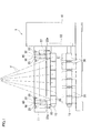
Fig. 1 is a front elevation of a yarn winding device according to an embodiment of the present invention. -
Fig. 2 is a profile of the yarn winding device. -
Fig. 3 is an enlarged view of two guide units which are provided at one end portion of the supporting plate to be adjacent to each other. -
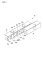
Fig. 4 is an oblique perspective view of a single guide unit. -
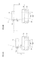
Fig. 5A is a horizontal cross section of the guide unit and shows a roller whose axis is tilted with respect to the direction in which the guide members oppose each other. -
Fig. 5B is a horizontal cross section of the guide unit and shows a roller whose axis is tilted in the direction opposite to the roller inFig. 5A , with respect to the direction in which the guide members oppose each other. -
Fig. 5C is a horizontal cross section of the guide unit and shows a roller having a protruding portion. -
Fig. 6A is a front enlarged view of the bobbin holder, the contact roller, and the traverse unit, showing the relation between the position and traversal width of the traverse unit and the winding width of yarns. -
Fig. 6B is another enlarged view. -
Fig. 7 is an oblique perspective view of amodification 1, which is equivalent toFig. 4 . - The following will describe an embodiment of the present invention. As shown in
Fig. 1 , ayarn winding device 1 serially receives a plurality of (6 in the present embodiment) yarns Y from an unillustrated spinning machine. Thisyarn winding device 1 is structured to form a plurality ofpackages 21 by winding the yarns Y supplied from the spinning machine onto a plurality ofbobbins 20. - As shown in
Fig. 1 andFig. 2 , theyarn winding device 1 includes components such as amain body frame 10, anelevation frame 11 attached to themain body frame 10 to be vertically movable (elevatable), a disc-shapedturret 12 attached to themain body frame 10 to be rotatable, twobobbin holders 13 supported by themain body frame 10 via theturret 12 and to each of which a plurality ofbobbin 20 are attached, atraverse unit 14 which traverses yarns Y which are to be wound onto thebobbins 20, and acontact roller 15 which contacts thebobbins 20 attached to thebobbin holder 13 at the winding position P1 (seeFig. 2 ). - The disc-shaped
turret 12 is attached to themain body frame 10 to be rotatable and to be in parallel to the vertical surface of themain body frame 10. At two positions which are symmetrical about the rotation center of theturret 12, the twobobbin holders 13 are provided to extend in the horizontal direction orthogonal to theturret 12 and to be rotatable. Furthermore, these twobobbin holders 13 are arranged to rotate together with theturret 12. As shown inFig. 1 , to each of the twobobbin holders 13, a plurality of (6 in the present embodiment)bobbins 20 are attached to form a single line along the axial direction of thebobbin holder 13. - The
turret 12 is rotated by an unillustrated motor. As theturret 12 rotates, each of the twobobbin holders 13 moves between a winding position P1 where the bobbin holder contacts thecontact roller 15 and the yarns Y are wound onto thebobbins 20 and a standby position P2 which is symmetrical with the winding position P1 about the rotation axis of theturret 12. As the winding to the yarns Y onto thebobbins 20 attached to thebobbin holder 13 at the winding position P1 is completed, Thebobbin holder 13 at the winding position P1 is replaced with thebobbin holder 13 at the standby position P2. - The two
bobbin holders 13 supported by theturret 12 are rotated by an unillustrated motor, respectively. As thebobbin holder 13 at the winding position P1 rotates, the yarns Y are wound onto thebobbins 20 attached to thisbobbin holder 13. - The elevation frame 11 (supporting frame) is a frame which is long along the axial direction of the
bobbin holders 13. Thiselevation frame 11 is supported by themain body frame 10 at the base end portion in the longitudinal direction to be movable (elevatable) in vertical directions (directions approaching and away from the bobbin holder) while being kept to be in parallel to thebobbin holders 13. More specifically, as shown inFig. 2 , the longitudinal base end portion of theelevation frame 11 is supported by twoguide shafts 26 which are fixed to themain body frame 10 to be vertically movable. Furthermore, theelevation frame 11 is moved in vertical directions by anelevation mechanism 28 including anelevation drive motor 27. Theyarn winding device 1 arranged as described above is particularly suitable for winding yarns Y while applying a relatively low contact pressure onto thepackages 21. - As shown in
Fig. 2 , theelevation frame 11 is provided with a plurality oftraverse units 14 corresponding to therespective bobbins 20 attached to thebobbin holder 13 at the winding position P1, and eachtraverse unit 14 is provided with atraverse guide 14a. While the yarns Y are placed on the respective traverse guides 14a, eachtraverse unit 14 causes thetraverse guide 14a to reciprocate within a predetermined traversal range along the axial direction of the bobbin holder 13 (i.e. the direction orthogonal to the surface ofFig. 2 ). As such, the yarns Y are wound onto the correspondingbobbins 20 while being traversed. - The
elevation frame 11 is connected to a supporting plate 22 (roller supporter) which supports thecontact roller 15. More specifically, this supportingplate 22 is long in the longitudinal direction of theelevation frame 11, and is connected to theelevation frame 11 to be vertically movable viaguide units 25 which are provided at the respective end portions of the supportingplate 22 in the longitudinal direction. Furthermore, at the respective end portions of the supportingplate 22 in the longitudinal direction, twopivot portions 22a are provided, respectively. - As shown in
Fig. 1 , thecontact roller 15 is a tube which is substantially as long as thebobbin holder 13, and is rotatably supported by the above-described twopivot portions 22a of the supportingplate 22 to be in parallel to thebobbin holders 13. Thecontact roller 15 is arranged to be able to contact the outer circumferences of either allbobbins 20 attached to thebobbin holder 13 at the winding position P1 or allpackages 21 formed by winding the yarns Y onto thebobbins 20. When the yarns Y are wound onto thebobbins 20, thecontact roller 15 rotates while applying a predetermined contact pressure to eachpackage 21, so as to adjust the shape of eachpackage 21. Furthermore, the supportingplate 22 and thecontact roller 15 are guided by theguide units 25 so as to change their relative positions with respect to theelevation frame 11, in the direction approaching thebobbins 20 at the winding position P1 (i.e. downward) and in the direction away from these bobbins 20 (i.e. upward). - Now, the
guide unit 25 will be detailed below. In the present embodiment, as shown inFig. 1 , theguide units 25 are provided at the longitudinal end portions of the supportingplate 22, respectively. Furthermore, at each of the end portions of the supportingplate 22, twoguide units 25 are provided to be adjacent to the end portion. In other words, the supportingplate 22 is connected to theelevation frame 11 via fourguide units 25, i.e. two guide units at each end portion. - Each
guide unit 25 is a so-called cross-roller-type guide unit. As shown inFig. 3 to Fig. 5C , eachguide unit 25 includes afirst guide member 30 which vertically extends and is fixed to theelevation frame 11, asecond guide member 31 which also vertically extends and is fixed to the supportingplate 22, and a plurality ofrollers first guide member 30 and thesecond guide member 31 to be aligned in the longitudinal direction of thesemembers 30 and 31 (i.e. in the vertical direction). - As shown in
Fig. 3 , to theelevation frame 11, afastener 40 having a vertically-extendingprotruding portion 40a and two attachingportions 40b on the respective sides of the protrudingportion 40a is fixed at the protrudingportion 40a by using a bolt. To the two attachingportions 40b of thisfastener 40, thefirst guide members 30 of the twoguide units 25 are fixed by bolts, respectively. As shown inFig. 4 andFig. 5A to Fig. 5C , on the one side face of the first guide member 30 (i.e. the face opposite to the protrudingportion 40a inFig. 3 ), a first V-shapedgroove 30a which is V-shaped in cross section is formed in vertical directions along the entire length of theguide member 30. - As shown in
Fig. 3 , to the back surface of the supporting plate 22 (i.e. the surface opposite to the contact roller 15),second guide members 31 of the twoguide units 25 are fixed by bolts. These twosecond guide members 31 are arranged to sandwich the twofirst guide members 30 fixed to theelevation frame 11. As shown inFig. 4 , on one side face of the second guide member 31 (i.e. on the surface opposing the first guide member 30), a second V-shapedgroove 31a which is V-shaped in cross section is formed to vertically extend along the entire length of thesecond guide member 31. In other words, in each of the right and leftguide units 25 shown inFig. 3 , the first V-shapedgroove 30a of thefirst guide member 30 and the second V-shapedgroove 31a of thesecond guide member 31 oppose each other. - As show in
Fig. 4 andFig. 5A to Fig. 5C , the space formed by the first V-shapedgroove 30a and the second V-shapedgroove 31a opposing each other houses a plurality of column-shapedrollers roller 32a is, as shown inFig. 5A , arranged so that its rotation axis C1 is tilted leftward for 45 degrees with respect to the direction in which theguide members Fig. 5A ), whereas theroller 32b is, as shown inFig. 5B , arranged so that its rotation axis C2 is tilted rightward for 45 degrees with respect to that opposing direction. In short, the axes of therespective rollers rollers guide members - The
first guide member 30 and thesecond guide member 31 are fixed to theelevation frame 11 and the supportingplate 22, respectively, while a predetermined nipping load (pre-load) is being applied to the guide members. For this reason, as shown inFig. 5A to Fig. 5C , therollers guide members groove 30a and the second V-shapedgroove 31a, at the two positions (A and B) on the outer circumferences thereof, which positions are symmetrical with each other about the rotation axis C1 or C2. - With this arrangement, when the
first guide member 30 and thesecond guide member 31 move relative to each other, therollers elevation frame 11 is only the rolling resistances of therollers - In addition to the above, in the
guide unit 25, therollers 32b restrain theguide members rollers 32a and therollers 32a restrain theguide members rollers 32b. For this reason, it is possible to restrain the supportingplate 22 and theelevation frame 11 from rattling in the horizontal direction orthogonal to the moving direction (i.e. in the direction in parallel to the surfaces ofFig. 5A to Fig. 5C ). - Because of the above, the
frame 11 and the supportingplate 22, which are connected with each other via theguide unit 25, smoothly move relative to each other. - In addition to the above, on the outer circumference of the roller 32a1 which is one of the
rollers 32a, a plurality of protrudingportions 41 each being substantially hemispherical are formed along the circumferential direction. Correspondingly, on the surfaces of the first V-shapedgroove 30a and the second V-shapedgroove 31a at which surfaces the grooves contact therollers 32a, a plurality ofconcave portions 42 are formed along the longitudinal direction of theguide members portions 41. In the present embodiment, the protrudingportions 41 formed on the roller 32a1 and theconcave portions 42 formed on the first V-shapedgroove 30a and the second V-shapedgroove 31a constitute the anti-slip means of the present invention. - Between the
first guide member 30 and thesecond guide member 31 is provided aroller supporter 33. Thisroller supporter 33 has a plurality of throughholes 33a and a plurality of holdinghooks 33b corresponding to the respective throughholes 33a. Therollers holes 33a of theroller supporter 33 are arranged not to drop out by being stopped by the holdinghooks 33b. Therollers - In the present embodiment, the roller 32a1 is provided with the protruding
portions 41 and the V-shapedgrooves concave portions 42. Because of this arrangement, as thefirst guide member 30 and thesecond guide member 31 move relative to each other, therollers portions 41 fits in the correspondingconcave portion 42, in accordance with the relative positions of thefirst guide member 30 and thesecond guide member 31. As the protrudingportion 41 fits in theconcave portion 42, the roller 32a1 does not slip with respect to theguide members guide members roller supporter 33 to which the roller 32a1 is attached does not slip and theother rollers roller supporter 33 do not slip. - In other words, the protruding
portions 41 and theconcave portions 42 constituting the anti-slip means of the present invention allow therollers guide members rollers roller supporter 33 from slipping with respect to theguide members - In the present embodiment, since the
rollers roller supporter 33, as described above, the slipping of allrollers portions 41 on a single roller 32a1. It is therefore unnecessary to form protrudingportions 41 on all of therollers - Now, how packages 21 are formed by winding yarns Y onto
bobbins 20 in theyarn winding device 1 will be detailed. As described above, in theyarn winding device 1, a plurality of yarns Y are wound onto a plurality ofbobbins 20 attached to thebobbin holder 13 at the winding position P1, while being traversed by thetraverse unit 14. - As the diameters of the
packages 21 increase on account of the increase in the amounts of yarns Y wound onto thebobbins 20, thecontact roller 15 and the supportingplate 22 are pushed up by thepackages 21. In this regard, since theelevation frame 11 is connected to the supportingplate 22 via theguide unit 25, thecontact roller 15 and the supportingplate 22 smoothly move as described above. On account of the above, the contact pressures from thecontact roller 15 to therespective packages 21 are unlikely to be inconsistent. - When as in the present embodiment the yarns Y are wound onto the
bobbins 20 while being traversed by thetraverse unit 14, as shown inFig. 6A , a part of the yarn Y which part is placed on thetraverse guide 14a is positionally deviated from a part of the yarn Y which part is wound onto thebobbin 20, in the axial direction of the bobbin 20 (in short, traverse delay occurs). In this case, a part of the yarn Y which part is between thetraverse guide 14a and thebobbin holder 13 is tilted at a predetermined winding angle θ toward the center of thebobbin 20 in the axial direction, with respect to the radial direction of thebobbin 20. The winding angle θ is determined based on the traverse speed and the rotation speed of thebobbin 20. For this reason, a part of the yarn Y which has already been wound onto thebobbin 20 is temporarily put on hold when the traversal by thetraverse unit 14 is reversed. Provided that the winding width of the yarn Y on thebobbin 20 is constant, the yarn Y is thicker at the end portions of thepackage 21 in the axial direction than the remaining portions, and hence the problem of so-called saddle bag at ends occurs at the both end portions of thepackage 21 in the axial direction. - To solve this problem, the
yarn winding device 1 is arranged so that, in normal winding, as shown inFig. 6A , the yarn Y is wound while keeping the length (free length) of the part of the yarn Y between thetraverse guide 14a and thebobbin holder 13 to be L1 in the vertical direction, and the elevation frame 11 (traverse unit 14) is temporarily moved up so that the free length becomes L2 (>L1) and then moved down to the original position at regular intervals (e.g. once in about one minutes) as shown inFig. 6B . This operation is called creeping. - In regard to the above, since the winding angle θ is determined as described above by the traverse speed and the rotation speed of the bobbin and is not influenced by the free length, the positional deviation between the part of the yarn Y placed on the
traverse guide 14a and the part of the yarn Y wound on thebobbin 20 increases in the axial direction of thebobbin 20, as the free length increases. - For the reason above, in the normal winding, i.e., when the free length is L1, as shown in
Fig. 6A , the yarn Y is wound onto thebobbin 20 with the winding width W1 which is shorter than the traversal width W0 of thetraverse unit 14. On the other hand, when thetraverse unit 14 has been moved up, i.e., when the free length is L2, as shown inFig. 6B , the yarn Y is wound onto thebobbin 20 with the winding width W2 which is shorter than the winding width W1. - As such, it is possible in
yarn winding device 1 to shorten the winding width of the yarn Y on thebobbin 20 by moving up thetraverse unit 14. As the winding width of the yarn Y on thebobbin 20 is shortened, the thickness of the yarn Y at the both end portions of thepackage 21 in the axial direction is reduced, and hence the problem of saddle bag at ends in thepackage 21 is resolved. - In this regard, to prevent the occurrence of the problem of saddle bag at ends in the
package 21 by moving up and down thetraverse unit 14, the up-down of theelevation frame 11 is repeated (e.g. about several tens to several hundreds of times) while asingle package 21 is formed. - As the up-down of the
elevation frame 11 is repeated in this way, thefirst guide member 30 and thesecond guide member 31 repeatedly move relative to each other. For this reason, when the protrudingportions 41 and theconcave portions 42 are not provided, therollers roller supporter 33 provided between thefirst guide member 30 and thesecond guide member 31 vertically slip with respect to theguide members - As the positional deviation of the
rollers roller supporter 33 becomes significant, therollers roller supporter 33 may drop off from one of theguide members first guide member 30 is being moved up or down. Furthermore, even if unillustrated stoppers are provided at the ends of theguide members rollers roller supporter 33 from dropping off, thefirst guide member 30 and thesecond guide member 31 may not smoothly move relative to each other because one of therollers roller supporter 33 contacts the stopper. - In regard to the above, the above-described problem does not occur in the embodiment because, as described above, the slipping of the
rollers roller supporter 33 is prevented in such a way that the protrudingportions 41 formed on the outer circumference of the roller 32a1 fit in theconcave portions 42 formed on the first V-shapedgroove 30a and the second V-shapedgroove 31a. - While the present invention has been described in conjunction with the specific embodiment outlined above, it is evident that many alternatives, modifications and variations will be apparent to those skilled in the art. Various changes may be made without departing from the spirit and scope of the invention.
- According to a modification (modification 1), as shown in
Fig. 7 , in place of the protrudingportions 41 and the concave portions 92, thefirst guide member 30 and thesecond guide member 31 are provided with rack gears 51, respectively, whereas theroller supporter 33 is provided with apinion gear 52 corresponding to the rack gears 51. In themodification 1, the two rack gears 51 and thepinion gear 52 constitute the anti-slip means of the present invention. - The rack gears 51 are provided at the respective bottoms of the first V-shaped
groove 30a and the second V-shapedgroove 31a, and extend along the longitudinal direction of theguide members pinion gear 52 is provided in a throughhole 33c of theroller supporter 33. Thisgear 52 is rotatable about anaxis 52a which is orthogonal to the direction in which thefirst guide member 30 opposes thesecond guide member 31, and substantially halves of thegear 52 jut out from both sides of theroller supporter 33 in the thickness directions. Thepinion gear 52 engages with the respective rack gears 51 of thefirst guide member 30 and thesecond guide member 31. - Also in this case, as the elevation frame 11 (see
Fig. 1 ) moves up or down and thefirst guide member 30 and thesecond guide member 31 move relative to each other, therollers guide members guide members pinion gear 52 of theroller supporter 33, therollers guide members pinion gear 52 prevent therollers roller supporter 33 from slipping while allowing therollers - Also in this case, since the
rollers roller supporter 33, it is possible to prevent allrollers pinion gear 52 to theroller supporter 33. - In addition to the above, the anti-slip means may have an arrangement different from the above-described
protruding portions 41 and theconcave portions 42 or the above-described rack gears 51 and thepinion gear 52, as long as the vertical slipping of therollers guide members rollers guide members - In addition to the above, while in the embodiment above the protruding
portions 41 are formed on only one roller 32a1, the protrudingportions 41 may be formed on two ormore rollers 32a. Alternatively, the protrudingportions 41 are formed on at least one of therollers 32a and at least one of therollers 32b, and correspondingly theconcave portions 42 are formed on the surfaces of the both first V-shapedgroove 30a and the second V-shapedgroove 31a at which surfaces the grooves contact therollers - In addition to the above, while in the embodiment above the
rollers roller supporter 33 so that the positional relations of therollers roller supporter 33 may not be provided. The slipping of therollers first guide member 30 and thesecond guide member 31 can be prevented also in this case, by forming the protrudingportions 41 on each of therollers - In addition to the above, while in the embodiment above the
traverse unit 14 is periodically moved up and down while the yarns Y are wound onto thebobbin 20, thetraverse unit 14 may be moved up and down not periodically but at random timings during the winding of the yarns Y, for example. Furthermore, thetraverse unit 14 may not always be moved up to the same height. For example, the height to which thetraverse unit 14 is moved up may be changed each time the creeping is carried out. - In addition to the above, while in the embodiment above the problem of saddle bag at ends in the packages is prevented by moving up and down the
traverse unit 14, this arrangement is not prerequisite. For example, the problem of saddle bag at ends in thepackages 21 may be prevented by another method, e.g. thetraverse unit 14 is arranged so that its traversal width is changeable and the winding width of the yarn Y is reduced by temporarily shortening the traversal width. Furthermore, the yarn winding device may not perform the operation to prevent the problem of saddle bag at ends in the packages. - When the
elevation frame 11 is not moved up and down while the yarns Y are wound onto thebobbins 20, as described above, thefirst guide member 30 and thesecond guide member 31 move relative to each other when thecontact roller 15 and the supportingplate 22 are pushed up by thepackages 21. The positional deviations of therollers roller supporter 33 also occur in this case if the protrudingportions 41 and theconcave portions 42 are not formed. - In this case, however, the relative movement of the
first guide member 30 and thesecond guide member 31 only occurs when thecontact roller 15 and the supportingplate 22 are pushed up by thepackages 21 and when these components moves down to the original positions during a period which is after the formation of thepackages 21 and before the formation of the next packages 21. In short, while asingle package 21 is formed, thefirst guide member 30 and thesecond guide member 31 move relative to each other only twice. For this reason, the positions deviations of therollers roller supporter 33 while asingle package 21 is formed are small, and hence therollers roller supporter 33 are not significantly deviated from the original positions while a single package is formed, even if the protrudingportions 41 and theconcave portions 42 are not formed. - In addition to the above, when the
guide members rollers roller supporter 33 to their original positions by moving thefirst guide member 30 and thesecond guide member 31 relative to each other while keeping theroller supporter 33 to contact the stopper in such a way that, for example, each time a predetermined number ofpackages 21 are formed, each of thefirst guide member 30 and thesecond guide member 31 is caused to move round its range of movement. As such, this operation prevents the positional deviations of therollers roller supporter 33 even if a plurality ofpackages 21 are successively formed. - The operation above, however, is disadvantageous in that, since the
roller supporter 33 collides the stopper, components such as therollers roller supporter 33 receive a severe impact, and this may shorten the life of the components such as therollers roller supporter 33. - In this regard, also in the case above, the slipping of the
rollers roller supporter 33 is prevented by the protrudingportions 41 formed on the outer circumference of the roller 32a1 and theconcave portions 42 formed on the first V-shapedgroove 30a and the second V-shapedgroove 31a in the same manner as the embodiment above, with the result that it is unnecessary to perform the operation to return therollers roller supporter 33 to the original positions, by which the components such as theroller supporter 33 receive a severe impact. - In addition to the above, while in the embodiment above the
guide unit 25 is a so-called cross-roller-type guide unit in whichrollers grooves guide members rollers first guide member 30 and thesecond guide member 31 to be aligned in the longitudinal direction of theguide members - In addition to the above, the number of
guide units 25 which vertically guide thecontact roller 15 with respect to theelevation frame 11 may be suitably changed in accordance with the design conditions such as the length and weight of thecontact roller 15 and the length of elevation.
Claims (6)
- A yarn winding device comprising:a bobbin holder which is supported by a main body frame and to which bobbins are attached;a supporting frame which is supported by the main body frame to be movable in directions approaching and away from the bobbin holder;a contact roller which is arranged to be in parallel to the bobbin holder and rotates while contacting either the outer circumferences of the bobbins or the outer circumferences of packages formed by winding yarns onto the bobbins;a roller supporter which is provided on the supporting frame to be movable in the directions approaching and away from the bobbin holder and rotatably supports the contact roller; anda guide unit which guides the supporting frame and the roller supporter in the directions approaching and away from the bobbin holder,the guide unit including:a first guide member fixed to the supporting frame;a second guide member fixed to the roller supporter to oppose the first guide member;rollers provided between the first guide member and the second guide member; andan anti-slip means which allows the rollers to roll in the directions approaching and away from the bobbin holder with respect to the first guide member and the second guide member and prevents the rollers from slipping in the directions approaching and away from the bobbin holder with respect to the first guide member and the second guide member.
- The yarn winding device according to claim 1, further comprising:a roller supporting component which maintains positional relations of the rollers by connecting the rollers with one another.
- The yarn winding device according to claim 2, wherein,
the anti-slip means includes:concave portions which are formed, along the directions approaching and away from the bobbin holder, on surfaces of the first guide member and the second guide member at which surfaces the first and second guide members contact the rollers; andprotruding portions which correspond to the respective concave portions, are formed on the outer circumference of at least one of the rollers along the circumferential direction, and are able to fit in the corresponding concave portions. - The yarn winding device according to claim 2, wherein,
the anti-slip means includes:rack gears provided in the first guide member and the second guide member, respectively; anda pinion gear which is provided in the roller supporting component and engages with the rack gears. - The yarn winding device according to any one of claims 1 to 4, wherein,
the supporting frame is provided with a traverse unit which traverses the yarns in the axial directions of the bobbins, and
the distance between the traverse unit and the bobbin holder is changeable by moving the supporting frame having the traverse unit in one of the directions approaching and away from the bobbin holder. - The yarn winding device according to any one of claims 1 to 5, wherein,
the first guide member has a first V-shaped groove which is substantially V-shaped in cross section and extends in the directions approaching and away from the bobbin holder,
the second guide member has a second V-shaped groove which is substantially V-shaped in cross section and extends in the directions approaching and away from the bobbin holder, and
the rollers are arranged so that each of the rollers contacts both of the first V-shaped groove and the second V-shaped groove at positions on the outer circumference which positions are symmetrical about the rotation axis of the rollers and axes of neighboring ones of the rollers are orthogonal to each other.
Applications Claiming Priority (1)
| Application Number | Priority Date | Filing Date | Title |
|---|---|---|---|
| JP2010187165A JP5702563B2 (en) | 2010-08-24 | 2010-08-24 | Yarn winding machine |
Publications (3)
| Publication Number | Publication Date |
|---|---|
| EP2423143A2 true EP2423143A2 (en) | 2012-02-29 |
| EP2423143A3 EP2423143A3 (en) | 2013-03-06 |
| EP2423143B1 EP2423143B1 (en) | 2014-10-01 |
Family
ID=44510792
Family Applications (1)
| Application Number | Title | Priority Date | Filing Date |
|---|---|---|---|
| EP11176553.3A Active EP2423143B1 (en) | 2010-08-24 | 2011-08-04 | Use of a yarn winding device |
Country Status (4)
| Country | Link |
|---|---|
| EP (1) | EP2423143B1 (en) |
| JP (1) | JP5702563B2 (en) |
| KR (1) | KR101485444B1 (en) |
| CN (1) | CN102431838B (en) |
Cited By (2)
| Publication number | Priority date | Publication date | Assignee | Title |
|---|---|---|---|---|
| CN114453376A (en) * | 2022-02-28 | 2022-05-10 | 山东联海建筑科技股份有限公司 | A dust-proof net storage device for building construction |
| EP4286702A4 (en) * | 2021-01-29 | 2024-12-04 | THK Co., Ltd. | LINEAR MOVEMENT GUIDE DEVICE |
Families Citing this family (9)
| Publication number | Priority date | Publication date | Assignee | Title |
|---|---|---|---|---|
| CN106885769A (en) * | 2017-02-17 | 2017-06-23 | 四川省宜宾惠美线业有限责任公司 | A kind of method of quick detection textile color stability |
| JP6935243B2 (en) * | 2017-06-21 | 2021-09-15 | Tmtマシナリー株式会社 | Thread winder |
| CN107381210A (en) * | 2017-06-29 | 2017-11-24 | 南京律智诚专利技术开发有限公司 | A kind of winding element for processing automotive trim composite fibre |
| CN110822042A (en) * | 2018-08-14 | 2020-02-21 | 咸阳蓝博机械有限公司 | Rack anti-creep cross guide rail pair |
| CN111022494B (en) * | 2018-10-09 | 2021-08-24 | 全研科技有限公司 | High-load slide rail structure |
| KR200488494Y1 (en) * | 2018-11-02 | 2019-05-22 | 서호삼 | Apparatus for cutting mesh material for dryvit |
| JP7522054B2 (en) * | 2021-01-29 | 2024-07-24 | Thk株式会社 | Linear guide device |
| CN113734891A (en) * | 2021-09-10 | 2021-12-03 | 苏州赛文纺织科技有限公司 | Winding roller positioning device for spinning |
| CN114321176B (en) * | 2021-12-31 | 2024-02-20 | 常州市双爱家私股份有限公司 | Built-in sliding device for lifting table and chair |
Citations (2)
| Publication number | Priority date | Publication date | Assignee | Title |
|---|---|---|---|---|
| JP2005225611A (en) | 2004-02-13 | 2005-08-25 | Tmt Machinery Inc | Elastic yarn winding method and elastic yarn winding machine |
| JP2008290821A (en) | 2007-05-23 | 2008-12-04 | Tmt Machinery Inc | Yarn winding machine |
Family Cites Families (8)
| Publication number | Priority date | Publication date | Assignee | Title |
|---|---|---|---|---|
| JPS5614434Y2 (en) * | 1976-06-24 | 1981-04-04 | ||
| JP3242503B2 (en) * | 1993-09-27 | 2001-12-25 | 日本トムソン株式会社 | Rolling bearing for finite linear motion |
| JP3896200B2 (en) * | 1997-10-09 | 2007-03-22 | 日本トムソン株式会社 | Finite linear guideway and finite linear guide unit incorporating the same |
| JP3945060B2 (en) * | 1999-01-13 | 2007-07-18 | 村田機械株式会社 | Spinning winder |
| JP4413530B2 (en) * | 2003-05-28 | 2010-02-10 | 日本ベアリング株式会社 | Sliding device |
| JP4252887B2 (en) * | 2003-11-28 | 2009-04-08 | 日本ベアリング株式会社 | Sliding device |
| JP4500278B2 (en) * | 2006-02-28 | 2010-07-14 | 日本トムソン株式会社 | Finite linear motion guide unit equipped with cage slip prevention mechanism |
| JP4856794B2 (en) * | 2007-03-26 | 2012-01-18 | 日本ベアリング株式会社 | Sliding device |
-
2010
- 2010-08-24 JP JP2010187165A patent/JP5702563B2/en active Active
-
2011
- 2011-08-04 EP EP11176553.3A patent/EP2423143B1/en active Active
- 2011-08-18 KR KR20110082082A patent/KR101485444B1/en active Active
- 2011-08-22 CN CN201110241398.4A patent/CN102431838B/en active Active
Patent Citations (2)
| Publication number | Priority date | Publication date | Assignee | Title |
|---|---|---|---|---|
| JP2005225611A (en) | 2004-02-13 | 2005-08-25 | Tmt Machinery Inc | Elastic yarn winding method and elastic yarn winding machine |
| JP2008290821A (en) | 2007-05-23 | 2008-12-04 | Tmt Machinery Inc | Yarn winding machine |
Cited By (3)
| Publication number | Priority date | Publication date | Assignee | Title |
|---|---|---|---|---|
| EP4286702A4 (en) * | 2021-01-29 | 2024-12-04 | THK Co., Ltd. | LINEAR MOVEMENT GUIDE DEVICE |
| US12410834B2 (en) | 2021-01-29 | 2025-09-09 | Thk Co., Ltd. | Linear motion guide apparatus |
| CN114453376A (en) * | 2022-02-28 | 2022-05-10 | 山东联海建筑科技股份有限公司 | A dust-proof net storage device for building construction |
Also Published As
| Publication number | Publication date |
|---|---|
| KR101485444B1 (en) | 2015-01-22 |
| CN102431838A (en) | 2012-05-02 |
| JP2012046258A (en) | 2012-03-08 |
| EP2423143A3 (en) | 2013-03-06 |
| EP2423143B1 (en) | 2014-10-01 |
| KR20120025401A (en) | 2012-03-15 |
| CN102431838B (en) | 2016-08-03 |
| JP5702563B2 (en) | 2015-04-15 |
Similar Documents
| Publication | Publication Date | Title |
|---|---|---|
| EP2423143B1 (en) | Use of a yarn winding device | |
| EP2392532B1 (en) | Winder | |
| KR101196300B1 (en) | Yarn winder | |
| EP2548830B1 (en) | Spinning winder | |
| CN116457294B (en) | Packaging machine | |
| WO2014103479A1 (en) | Universal holding jig | |
| JP5827069B2 (en) | Transport device | |
| US8245541B2 (en) | Equipment for providing twist to an optical fiber | |
| EP4005959B1 (en) | Yarn winder | |
| EP1900661A2 (en) | Coiling machine | |
| JP5332337B2 (en) | Transport equipment and automatic warehouse | |
| JP6319079B2 (en) | Rover spinning equipment | |
| KR101040342B1 (en) | Panel feeder | |
| CA2627703C (en) | Core locking device | |
| KR101357058B1 (en) | Yarn winding machine and yarn winding method | |
| KR101504837B1 (en) | Coil stripper device | |
| EP3418231B1 (en) | Yarn winder | |
| WO2019155839A1 (en) | Movement guiding device | |
| JP6520331B2 (en) | Vehicle support roller | |
| JP3925186B2 (en) | Dust cover for linear motion device | |
| KR20120007690U (en) | Acontinuous guide device for plate |
Legal Events
| Date | Code | Title | Description |
|---|---|---|---|
| AK | Designated contracting states |
Kind code of ref document: A2 Designated state(s): AL AT BE BG CH CY CZ DE DK EE ES FI FR GB GR HR HU IE IS IT LI LT LU LV MC MK MT NL NO PL PT RO RS SE SI SK SM TR |
|
| AX | Request for extension of the european patent |
Extension state: BA ME |
|
| PUAI | Public reference made under article 153(3) epc to a published international application that has entered the european phase |
Free format text: ORIGINAL CODE: 0009012 |
|
| PUAL | Search report despatched |
Free format text: ORIGINAL CODE: 0009013 |
|
| AK | Designated contracting states |
Kind code of ref document: A3 Designated state(s): AL AT BE BG CH CY CZ DE DK EE ES FI FR GB GR HR HU IE IS IT LI LT LU LV MC MK MT NL NO PL PT RO RS SE SI SK SM TR |
|
| AX | Request for extension of the european patent |
Extension state: BA ME |
|
| RIC1 | Information provided on ipc code assigned before grant |
Ipc: B65H 54/72 20060101ALI20130128BHEP Ipc: B65H 54/38 20060101AFI20130128BHEP Ipc: F16C 33/30 20060101ALI20130128BHEP Ipc: B65H 67/048 20060101ALI20130128BHEP |
|
| 17P | Request for examination filed |
Effective date: 20130731 |
|
| RBV | Designated contracting states (corrected) |
Designated state(s): AL AT BE BG CH CY CZ DE DK EE ES FI FR GB GR HR HU IE IS IT LI LT LU LV MC MK MT NL NO PL PT RO RS SE SI SK SM TR |
|
| 17Q | First examination report despatched |
Effective date: 20130905 |
|
| REG | Reference to a national code |
Ref country code: DE Ref legal event code: R079 Ref document number: 602011010222 Country of ref document: DE Free format text: PREVIOUS MAIN CLASS: B65H0054380000 Ipc: F16C0029040000 |
|
| RIC1 | Information provided on ipc code assigned before grant |
Ipc: B65H 54/38 20060101ALI20140326BHEP Ipc: F16C 29/04 20060101AFI20140326BHEP Ipc: B65H 54/72 20060101ALI20140326BHEP Ipc: F16C 33/30 20060101ALI20140326BHEP Ipc: B65H 67/048 20060101ALI20140326BHEP |
|
| GRAP | Despatch of communication of intention to grant a patent |
Free format text: ORIGINAL CODE: EPIDOSNIGR1 |
|
| INTG | Intention to grant announced |
Effective date: 20140516 |
|
| GRAS | Grant fee paid |
Free format text: ORIGINAL CODE: EPIDOSNIGR3 |
|
| GRAA | (expected) grant |
Free format text: ORIGINAL CODE: 0009210 |
|
| AK | Designated contracting states |
Kind code of ref document: B1 Designated state(s): AL AT BE BG CH CY CZ DE DK EE ES FI FR GB GR HR HU IE IS IT LI LT LU LV MC MK MT NL NO PL PT RO RS SE SI SK SM TR |
|
| REG | Reference to a national code |
Ref country code: GB Ref legal event code: FG4D |
|
| REG | Reference to a national code |
Ref country code: CH Ref legal event code: EP Ref country code: AT Ref legal event code: REF Ref document number: 689689 Country of ref document: AT Kind code of ref document: T Effective date: 20141015 |
|
| REG | Reference to a national code |
Ref country code: IE Ref legal event code: FG4D |
|
| REG | Reference to a national code |
Ref country code: DE Ref legal event code: R096 Ref document number: 602011010222 Country of ref document: DE Effective date: 20141113 |
|
| REG | Reference to a national code |
Ref country code: NL Ref legal event code: VDEP Effective date: 20141001 |
|
| REG | Reference to a national code |
Ref country code: AT Ref legal event code: MK05 Ref document number: 689689 Country of ref document: AT Kind code of ref document: T Effective date: 20141001 |
|
| REG | Reference to a national code |
Ref country code: LT Ref legal event code: MG4D |
|
| PG25 | Lapsed in a contracting state [announced via postgrant information from national office to epo] |
Ref country code: NL Free format text: LAPSE BECAUSE OF FAILURE TO SUBMIT A TRANSLATION OF THE DESCRIPTION OR TO PAY THE FEE WITHIN THE PRESCRIBED TIME-LIMIT Effective date: 20141001 |
|
| PG25 | Lapsed in a contracting state [announced via postgrant information from national office to epo] |
Ref country code: PT Free format text: LAPSE BECAUSE OF FAILURE TO SUBMIT A TRANSLATION OF THE DESCRIPTION OR TO PAY THE FEE WITHIN THE PRESCRIBED TIME-LIMIT Effective date: 20150202 Ref country code: IS Free format text: LAPSE BECAUSE OF FAILURE TO SUBMIT A TRANSLATION OF THE DESCRIPTION OR TO PAY THE FEE WITHIN THE PRESCRIBED TIME-LIMIT Effective date: 20150201 Ref country code: FI Free format text: LAPSE BECAUSE OF FAILURE TO SUBMIT A TRANSLATION OF THE DESCRIPTION OR TO PAY THE FEE WITHIN THE PRESCRIBED TIME-LIMIT Effective date: 20141001 Ref country code: ES Free format text: LAPSE BECAUSE OF FAILURE TO SUBMIT A TRANSLATION OF THE DESCRIPTION OR TO PAY THE FEE WITHIN THE PRESCRIBED TIME-LIMIT Effective date: 20141001 Ref country code: CZ Free format text: LAPSE BECAUSE OF FAILURE TO SUBMIT A TRANSLATION OF THE DESCRIPTION OR TO PAY THE FEE WITHIN THE PRESCRIBED TIME-LIMIT Effective date: 20141001 Ref country code: LT Free format text: LAPSE BECAUSE OF FAILURE TO SUBMIT A TRANSLATION OF THE DESCRIPTION OR TO PAY THE FEE WITHIN THE PRESCRIBED TIME-LIMIT Effective date: 20141001 Ref country code: NO Free format text: LAPSE BECAUSE OF FAILURE TO SUBMIT A TRANSLATION OF THE DESCRIPTION OR TO PAY THE FEE WITHIN THE PRESCRIBED TIME-LIMIT Effective date: 20150101 |
|
| PG25 | Lapsed in a contracting state [announced via postgrant information from national office to epo] |
Ref country code: SE Free format text: LAPSE BECAUSE OF FAILURE TO SUBMIT A TRANSLATION OF THE DESCRIPTION OR TO PAY THE FEE WITHIN THE PRESCRIBED TIME-LIMIT Effective date: 20141001 Ref country code: AT Free format text: LAPSE BECAUSE OF FAILURE TO SUBMIT A TRANSLATION OF THE DESCRIPTION OR TO PAY THE FEE WITHIN THE PRESCRIBED TIME-LIMIT Effective date: 20141001 Ref country code: HR Free format text: LAPSE BECAUSE OF FAILURE TO SUBMIT A TRANSLATION OF THE DESCRIPTION OR TO PAY THE FEE WITHIN THE PRESCRIBED TIME-LIMIT Effective date: 20141001 Ref country code: RS Free format text: LAPSE BECAUSE OF FAILURE TO SUBMIT A TRANSLATION OF THE DESCRIPTION OR TO PAY THE FEE WITHIN THE PRESCRIBED TIME-LIMIT Effective date: 20141001 Ref country code: LV Free format text: LAPSE BECAUSE OF FAILURE TO SUBMIT A TRANSLATION OF THE DESCRIPTION OR TO PAY THE FEE WITHIN THE PRESCRIBED TIME-LIMIT Effective date: 20141001 Ref country code: GR Free format text: LAPSE BECAUSE OF FAILURE TO SUBMIT A TRANSLATION OF THE DESCRIPTION OR TO PAY THE FEE WITHIN THE PRESCRIBED TIME-LIMIT Effective date: 20150102 Ref country code: CY Free format text: LAPSE BECAUSE OF FAILURE TO SUBMIT A TRANSLATION OF THE DESCRIPTION OR TO PAY THE FEE WITHIN THE PRESCRIBED TIME-LIMIT Effective date: 20141001 Ref country code: PL Free format text: LAPSE BECAUSE OF FAILURE TO SUBMIT A TRANSLATION OF THE DESCRIPTION OR TO PAY THE FEE WITHIN THE PRESCRIBED TIME-LIMIT Effective date: 20141001 |
|
| REG | Reference to a national code |
Ref country code: DE Ref legal event code: R097 Ref document number: 602011010222 Country of ref document: DE |
|
| PG25 | Lapsed in a contracting state [announced via postgrant information from national office to epo] |
Ref country code: RO Free format text: LAPSE BECAUSE OF FAILURE TO SUBMIT A TRANSLATION OF THE DESCRIPTION OR TO PAY THE FEE WITHIN THE PRESCRIBED TIME-LIMIT Effective date: 20141001 Ref country code: DK Free format text: LAPSE BECAUSE OF FAILURE TO SUBMIT A TRANSLATION OF THE DESCRIPTION OR TO PAY THE FEE WITHIN THE PRESCRIBED TIME-LIMIT Effective date: 20141001 Ref country code: SK Free format text: LAPSE BECAUSE OF FAILURE TO SUBMIT A TRANSLATION OF THE DESCRIPTION OR TO PAY THE FEE WITHIN THE PRESCRIBED TIME-LIMIT Effective date: 20141001 Ref country code: EE Free format text: LAPSE BECAUSE OF FAILURE TO SUBMIT A TRANSLATION OF THE DESCRIPTION OR TO PAY THE FEE WITHIN THE PRESCRIBED TIME-LIMIT Effective date: 20141001 |
|
| PLBE | No opposition filed within time limit |
Free format text: ORIGINAL CODE: 0009261 |
|
| STAA | Information on the status of an ep patent application or granted ep patent |
Free format text: STATUS: NO OPPOSITION FILED WITHIN TIME LIMIT |
|
| 26N | No opposition filed |
Effective date: 20150702 |
|
| PG25 | Lapsed in a contracting state [announced via postgrant information from national office to epo] |
Ref country code: SI Free format text: LAPSE BECAUSE OF FAILURE TO SUBMIT A TRANSLATION OF THE DESCRIPTION OR TO PAY THE FEE WITHIN THE PRESCRIBED TIME-LIMIT Effective date: 20141001 |
|
| PG25 | Lapsed in a contracting state [announced via postgrant information from national office to epo] |
Ref country code: LU Free format text: LAPSE BECAUSE OF FAILURE TO SUBMIT A TRANSLATION OF THE DESCRIPTION OR TO PAY THE FEE WITHIN THE PRESCRIBED TIME-LIMIT Effective date: 20150804 Ref country code: MC Free format text: LAPSE BECAUSE OF FAILURE TO SUBMIT A TRANSLATION OF THE DESCRIPTION OR TO PAY THE FEE WITHIN THE PRESCRIBED TIME-LIMIT Effective date: 20141001 |
|
| REG | Reference to a national code |
Ref country code: CH Ref legal event code: PL |
|
| GBPC | Gb: european patent ceased through non-payment of renewal fee |
Effective date: 20150804 |
|
| PG25 | Lapsed in a contracting state [announced via postgrant information from national office to epo] |
Ref country code: CH Free format text: LAPSE BECAUSE OF NON-PAYMENT OF DUE FEES Effective date: 20150831 Ref country code: LI Free format text: LAPSE BECAUSE OF NON-PAYMENT OF DUE FEES Effective date: 20150831 |
|
| REG | Reference to a national code |
Ref country code: IE Ref legal event code: MM4A |
|
| REG | Reference to a national code |
Ref country code: FR Ref legal event code: ST Effective date: 20160429 |
|
| PG25 | Lapsed in a contracting state [announced via postgrant information from national office to epo] |
Ref country code: IE Free format text: LAPSE BECAUSE OF NON-PAYMENT OF DUE FEES Effective date: 20150804 Ref country code: GB Free format text: LAPSE BECAUSE OF NON-PAYMENT OF DUE FEES Effective date: 20150804 |
|
| PG25 | Lapsed in a contracting state [announced via postgrant information from national office to epo] |
Ref country code: FR Free format text: LAPSE BECAUSE OF NON-PAYMENT OF DUE FEES Effective date: 20150831 |
|
| PG25 | Lapsed in a contracting state [announced via postgrant information from national office to epo] |
Ref country code: MT Free format text: LAPSE BECAUSE OF FAILURE TO SUBMIT A TRANSLATION OF THE DESCRIPTION OR TO PAY THE FEE WITHIN THE PRESCRIBED TIME-LIMIT Effective date: 20141001 |
|
| PG25 | Lapsed in a contracting state [announced via postgrant information from national office to epo] |
Ref country code: BG Free format text: LAPSE BECAUSE OF FAILURE TO SUBMIT A TRANSLATION OF THE DESCRIPTION OR TO PAY THE FEE WITHIN THE PRESCRIBED TIME-LIMIT Effective date: 20141001 Ref country code: SM Free format text: LAPSE BECAUSE OF FAILURE TO SUBMIT A TRANSLATION OF THE DESCRIPTION OR TO PAY THE FEE WITHIN THE PRESCRIBED TIME-LIMIT Effective date: 20141001 Ref country code: HU Free format text: LAPSE BECAUSE OF FAILURE TO SUBMIT A TRANSLATION OF THE DESCRIPTION OR TO PAY THE FEE WITHIN THE PRESCRIBED TIME-LIMIT; INVALID AB INITIO Effective date: 20110804 |
|
| PG25 | Lapsed in a contracting state [announced via postgrant information from national office to epo] |
Ref country code: TR Free format text: LAPSE BECAUSE OF FAILURE TO SUBMIT A TRANSLATION OF THE DESCRIPTION OR TO PAY THE FEE WITHIN THE PRESCRIBED TIME-LIMIT Effective date: 20141001 |
|
| PG25 | Lapsed in a contracting state [announced via postgrant information from national office to epo] |
Ref country code: BE Free format text: LAPSE BECAUSE OF FAILURE TO SUBMIT A TRANSLATION OF THE DESCRIPTION OR TO PAY THE FEE WITHIN THE PRESCRIBED TIME-LIMIT Effective date: 20141001 |
|
| PG25 | Lapsed in a contracting state [announced via postgrant information from national office to epo] |
Ref country code: MK Free format text: LAPSE BECAUSE OF FAILURE TO SUBMIT A TRANSLATION OF THE DESCRIPTION OR TO PAY THE FEE WITHIN THE PRESCRIBED TIME-LIMIT Effective date: 20141001 |
|
| PG25 | Lapsed in a contracting state [announced via postgrant information from national office to epo] |
Ref country code: AL Free format text: LAPSE BECAUSE OF FAILURE TO SUBMIT A TRANSLATION OF THE DESCRIPTION OR TO PAY THE FEE WITHIN THE PRESCRIBED TIME-LIMIT Effective date: 20141001 |
|
| P01 | Opt-out of the competence of the unified patent court (upc) registered |
Effective date: 20230426 |
|
| PGFP | Annual fee paid to national office [announced via postgrant information from national office to epo] |
Ref country code: DE Payment date: 20250821 Year of fee payment: 15 |
|
| PGFP | Annual fee paid to national office [announced via postgrant information from national office to epo] |
Ref country code: IT Payment date: 20250822 Year of fee payment: 15 |