JP4252887B2 - Sliding device - Google Patents
Sliding device Download PDFInfo
- Publication number
- JP4252887B2 JP4252887B2 JP2003400699A JP2003400699A JP4252887B2 JP 4252887 B2 JP4252887 B2 JP 4252887B2 JP 2003400699 A JP2003400699 A JP 2003400699A JP 2003400699 A JP2003400699 A JP 2003400699A JP 4252887 B2 JP4252887 B2 JP 4252887B2
- Authority
- JP
- Japan
- Prior art keywords
- load
- rolling element
- sliding device
- rolling
- sliding
- Prior art date
- Legal status (The legal status is an assumption and is not a legal conclusion. Google has not performed a legal analysis and makes no representation as to the accuracy of the status listed.)
- Expired - Fee Related
Links
Images


Classifications
-
- F—MECHANICAL ENGINEERING; LIGHTING; HEATING; WEAPONS; BLASTING
- F16—ENGINEERING ELEMENTS AND UNITS; GENERAL MEASURES FOR PRODUCING AND MAINTAINING EFFECTIVE FUNCTIONING OF MACHINES OR INSTALLATIONS; THERMAL INSULATION IN GENERAL
- F16C—SHAFTS; FLEXIBLE SHAFTS; ELEMENTS OR CRANKSHAFT MECHANISMS; ROTARY BODIES OTHER THAN GEARING ELEMENTS; BEARINGS
- F16C29/00—Bearings for parts moving only linearly
- F16C29/04—Ball or roller bearings
- F16C29/041—Ball or roller bearings having rollers crossed within a row
-
- A—HUMAN NECESSITIES
- A63—SPORTS; GAMES; AMUSEMENTS
- A63B—APPARATUS FOR PHYSICAL TRAINING, GYMNASTICS, SWIMMING, CLIMBING, OR FENCING; BALL GAMES; TRAINING EQUIPMENT
- A63B22/00—Exercising apparatus specially adapted for conditioning the cardio-vascular system, for training agility or co-ordination of movements
- A63B22/20—Exercising apparatus specially adapted for conditioning the cardio-vascular system, for training agility or co-ordination of movements using rollers, wheels, castors or the like, e.g. gliding means, to be moved over the floor or other surface, e.g. guide tracks, during exercising
-
- F—MECHANICAL ENGINEERING; LIGHTING; HEATING; WEAPONS; BLASTING
- F16—ENGINEERING ELEMENTS AND UNITS; GENERAL MEASURES FOR PRODUCING AND MAINTAINING EFFECTIVE FUNCTIONING OF MACHINES OR INSTALLATIONS; THERMAL INSULATION IN GENERAL
- F16C—SHAFTS; FLEXIBLE SHAFTS; ELEMENTS OR CRANKSHAFT MECHANISMS; ROTARY BODIES OTHER THAN GEARING ELEMENTS; BEARINGS
- F16C29/00—Bearings for parts moving only linearly
- F16C29/04—Ball or roller bearings
- F16C29/043—Ball or roller bearings with two massive rectangular rails having facing grooves
-
- F—MECHANICAL ENGINEERING; LIGHTING; HEATING; WEAPONS; BLASTING
- F16—ENGINEERING ELEMENTS AND UNITS; GENERAL MEASURES FOR PRODUCING AND MAINTAINING EFFECTIVE FUNCTIONING OF MACHINES OR INSTALLATIONS; THERMAL INSULATION IN GENERAL
- F16C—SHAFTS; FLEXIBLE SHAFTS; ELEMENTS OR CRANKSHAFT MECHANISMS; ROTARY BODIES OTHER THAN GEARING ELEMENTS; BEARINGS
- F16C33/00—Parts of bearings; Special methods for making bearings or parts thereof
- F16C33/30—Parts of ball or roller bearings
- F16C33/306—Means to synchronise movements
-
- F—MECHANICAL ENGINEERING; LIGHTING; HEATING; WEAPONS; BLASTING
- F16—ENGINEERING ELEMENTS AND UNITS; GENERAL MEASURES FOR PRODUCING AND MAINTAINING EFFECTIVE FUNCTIONING OF MACHINES OR INSTALLATIONS; THERMAL INSULATION IN GENERAL
- F16C—SHAFTS; FLEXIBLE SHAFTS; ELEMENTS OR CRANKSHAFT MECHANISMS; ROTARY BODIES OTHER THAN GEARING ELEMENTS; BEARINGS
- F16C33/00—Parts of bearings; Special methods for making bearings or parts thereof
- F16C33/30—Parts of ball or roller bearings
- F16C33/34—Rollers; Needles
-
- F—MECHANICAL ENGINEERING; LIGHTING; HEATING; WEAPONS; BLASTING
- F16—ENGINEERING ELEMENTS AND UNITS; GENERAL MEASURES FOR PRODUCING AND MAINTAINING EFFECTIVE FUNCTIONING OF MACHINES OR INSTALLATIONS; THERMAL INSULATION IN GENERAL
- F16C—SHAFTS; FLEXIBLE SHAFTS; ELEMENTS OR CRANKSHAFT MECHANISMS; ROTARY BODIES OTHER THAN GEARING ELEMENTS; BEARINGS
- F16C33/00—Parts of bearings; Special methods for making bearings or parts thereof
- F16C33/30—Parts of ball or roller bearings
- F16C33/46—Cages for rollers or needles
- F16C33/4617—Massive or moulded cages having cage pockets surrounding the rollers, e.g. machined window cages
- F16C33/4623—Massive or moulded cages having cage pockets surrounding the rollers, e.g. machined window cages formed as one-piece cages, i.e. monoblock cages
-
- F—MECHANICAL ENGINEERING; LIGHTING; HEATING; WEAPONS; BLASTING
- F16—ENGINEERING ELEMENTS AND UNITS; GENERAL MEASURES FOR PRODUCING AND MAINTAINING EFFECTIVE FUNCTIONING OF MACHINES OR INSTALLATIONS; THERMAL INSULATION IN GENERAL
- F16C—SHAFTS; FLEXIBLE SHAFTS; ELEMENTS OR CRANKSHAFT MECHANISMS; ROTARY BODIES OTHER THAN GEARING ELEMENTS; BEARINGS
- F16C2300/00—Application independent of particular apparatuses
- F16C2300/02—General use or purpose, i.e. no use, purpose, special adaptation or modification indicated or a wide variety of uses mentioned
Description
本発明は、摺動装置に関するものである。 The present invention relates to a sliding device.
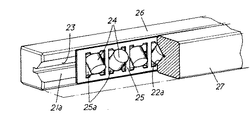
一般的な摺動装置として、図1,2に図示したように、基体29上に設けた軸21に、基部22bの左右に袖部22cを有する断面視略逆凹状の摺動体22が被嵌され、該摺動体22は軸21に対して往復摺動するように設けられ、軸21と摺動体22の間には、軸21の両側に設けられる第一負荷溝21aと該第一負荷溝21aと対向し摺動体22の左右の袖部22cの内面に夫々設けられる第二負荷溝22aとから成る負荷路23が設けられ、該負荷路23には複数の転動体24が所定間隔を保持した状態で配設され、前記摺動体22の摺動移動と共に、転動体24が転動移動するように構成されているものがある。尚、図中符号26は軸21に設けられた第一負荷部構成材、27は摺動体22に設けられた第二負荷部構成材である。
As a general sliding device, as shown in FIGS. 1 and 2, a
ところで、摺動体22は前記の通り、転動体24の転動移動を伴いながら軸21に対して摺動移動するが、転動移動の際、転動体24同志が衝突すると摺動体22の良好な摺動移動が阻害されたり、騒音の原因となってしまうため、従来の摺動装置には、図2に図示したように、前記負荷路23に、板体に転動体配設窓25aを形成した転動体保持器25を配設し、この転動体保持器25の転動体配設窓25aに転動体24を配設することで、転動体24同志の間隔を保持し、該転動体24同志の衝突を防止する構成を採用している。
By the way, as described above, the
一方、従来の摺動装置においては、摺動体22の往復摺動に伴い軸21及び摺動体22と転動体保持器25との相対位置が徐々にズレてしまう現象、所謂ミクロスリップ現象が生じることが知られている。
On the other hand, in the conventional sliding device, as the
このミクロスリップ現象による転動体保持器25のズレ動は、該転動体保持器25と転動体24とに摩擦を生じ、この摩擦により摺動体22の良好な摺動移動が阻害されたり、騒音の原因となったり、更に、ズレ動が大きくなると、転動体保持器25が破壊され、使用機器に重大な損傷を及ぼすこともある。
The displacement movement of the
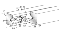
そこで、上述のミクロスリップ現象を防止するために、例えば、図3,4に図示したような特開平11−315831号(以下、特許文献1という。),図5,6に図示したような特開平11−315832号(以下、特許文献2という。)のように、転動体保持器25に複数の凸部30を有する円盤体32を結合すると共に、負荷路23にこの円盤体32の凸部30と凹凸係合する複数の凹部31を設け、この凸部30と凹部31とから成る凹凸係合機構を作用させて転動体保持器25を負荷路23上において移動させるように構成することで、該転動体保持器25の前記ズレ動を防止するようにしたものがあるが、構造が複雑で耐久性に劣り、メンテナンス性が悪くコスト高となることは避けられない。
Therefore, in order to prevent the above-described micro-slip phenomenon, for example, Japanese Patent Application Laid-Open No. 11-315831 (hereinafter referred to as Patent Document 1) as shown in FIGS. As in Kaihei 11-315832 (hereinafter referred to as Patent Document 2), a
具体的には、特許文献1,2は夫々、転動体保持器25の略中央部に、該転動体保持器25に結合される転動体24とは異なる円盤体32を設けた構成であり、この円盤体32は負荷路23から負荷を受けないため、凹凸係合機構の凹凸係合関係がルーズで(凹凸係合がしっかりと行われない)、ミクロスリップ現象を完全に防止できない。
Specifically, Patent Documents 1 and 2 each have a configuration in which a
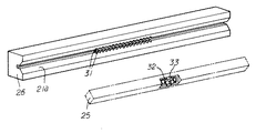
また、この円盤体32は転動体24に比して大きいため、摺動体の有効ストローク長が短くなり、この有効ストローク長を長く取ろうとすれば、その分転動体保持器25の長さを短くする必要があり、該転動体保持器25に保持される転動体24が減少し、負荷容量が低下するという問題がある。
Further, since this
更に、円盤体32は転動体保持器25に結合される構成であるため、この円盤体32を支承保持するための軸33が必要で、これらは通常樹脂で形成されることから精度及び剛性の点から加工が厄介である。
Further, since the
本発明は、上述のような現状に鑑み、負荷を受ける転動体と負荷路との間に凹凸係合関係を設け、これらを確実に凹凸係合させた状態で転動体保持器を負荷路上で移動させることができるから、ミクロスリップ現象を確実に抑制でき、しかも、これらを簡易な構成で実現できるため、生産性良好にしてコスト安な実用性に秀れる摺動装置を提供するものである。 In view of the present situation as described above, the present invention provides a concavo-convex engagement relationship between a rolling element that receives a load and a load path, and the rolling element retainer is placed on the load path in a state in which the concavo-convex engagement is ensured. Since it can be moved, the micro-slip phenomenon can be surely suppressed, and since these can be realized with a simple configuration, a sliding device with good productivity and excellent cost-effectiveness is provided. .
添付図面を参照して本発明の要旨を説明する。 The gist of the present invention will be described with reference to the accompanying drawings.
軸1に対して摺動体2が摺動するように設けられ、この軸1と摺動体2との間には負荷路3が設けられ、この負荷路3には複数の転動体4が配設され、この転動体4が前記負荷路3を転動移動するように構成された摺動装置であって、前記負荷路3に配設される前記転動体4の内、一若しくは複数の前記転動体5は、その長さ方向略中央位置にして周面5bに半球状の凸部5aが該転動体5の周方向に所定間隔で複数設けられ、一方、前記負荷路3には前記転動体5の凸部5aと合致係合する半球状の凹部3aが該負荷路3の長さ方向に該転動体5の凸部5aの間隔と同間隔で複数設けられ、前記転動体5は前記負荷路3に前記凸部5aと前記凹部3aとによって該負荷路3と凹凸係合状態で配設され、この負荷路3には前記転動体4,5を保持する転動体保持器6が配設され、前記凸部5a及び前記凹部3aはいずれかの該凸部5aがいずれかの該凹部3aに嵌入されるようにその間隔が設定されており、前記凸部5aが設けられた転動体5が前記凹凸係合状態を保持して前記負荷路3を転動移動するように構成されていることを特徴とする摺動装置に係るものである。
A sliding body 2 is provided to slide relative to the shaft 1, and a
また、請求項1記載の摺動装置において、前記転動体保持器6に保持される転動体4の内、中央の転動体5にのみ凸部5aが設けられ、前記負荷路3にしてこの中央の転動体5が移動する範囲には凹部3aが設けられていることを特徴とする摺動装置に係るものである。
Further, in the sliding device according to claim 1 , a
また、請求項1,2いずれか1項に記載の摺動装置において、前記転動体5と前記凸部5aとは一体成形されていることを特徴とする摺動装置に係るものである。
Further, in the sliding apparatus according to claim 1, 2 any one, wherein the
また、請求項1〜3いずれか1項に記載の摺動装置において、前記転動体4として円柱体が採用され、この円柱体は隣接する円柱体と異なる向きで配設され、また、前記凸部5aはこの円柱体の胴部5bに設けられていることを特徴とする摺動装置に係るものである。
Further, in the sliding device according to any one of claims 1 to 3 , a cylindrical body is adopted as the rolling element 4, and the cylindrical body is disposed in a different direction from an adjacent cylindrical body, and the convex The
また、請求項1〜4いずれか1項に記載の摺動装置において、前記負荷路3は、前記軸1に設けられる第一負荷溝1aと、前記摺動体2に設けられる第二負荷溝2aとで構成されていることを特徴とする摺動装置に係るものである。
Further, in the sliding apparatus according to any one of claims 1-4, wherein the
また、請求項5記載の摺動装置において、前記第一負荷溝1a及び第二負荷溝2aは、夫々断面視横V字状に形成され、この断面視横V字状の第一負荷溝1a及び第二負荷溝2aに前記転動体4が配設されていることを特徴とする摺動装置に係るものである。
Further, in the sliding device according to
また、請求項5,6いずれか1項に記載の摺動装置において、前記第一負荷溝1aは前記軸1に設けられる第一負荷部構成材7に形成され、前記第二負荷溝2aは前記摺動体2に設けられる第二負荷部構成材8に形成されていることを特徴とする摺動装置に係るものである。
Further, in the sliding apparatus according to any one of
また、請求項7記載の摺動装置において、前記転動体5,前記凸部5a,前記第一負荷部構成材7及び前記第二負荷部構成材8として夫々金属製のものが採用されていることを特徴とする摺動装置に係るものである。
Further, in the sliding device according to
本発明は上述のように構成したから、ミクロスリップ現象を確実に抑制でき、しかも、これらを簡易な構成で実現できる生産性良好にしてコスト安な実用性に秀れる摺動装置となる。 Since the present invention is configured as described above, the micro-slip phenomenon can be surely suppressed, and the sliding device can be realized with a simple configuration with good productivity and excellent cost-effective practicality.
好適と考える本発明の実施の形態を、図面に基づいてその作用効果を示して簡単に説明する。 An embodiment of the present invention considered to be suitable will be briefly described with reference to the drawings, showing its effects.
負荷を受ける転動体5が負荷路3と凹凸係合するから、該転動体5は軸1及び摺動体2に対して滑らず、よって、該転動体4,5を保持する転動体保持器6の軸1及び摺動体2に対するズレ動は生じない。
Since the
以上、本発明は、転動体保持器のミクロスリップ現象を防止でき、しかも、これを簡易な構成で実現できる生産性良好にしてコスト安な実用性に秀れる摺動装置となる。 As described above, the present invention is a sliding device that can prevent the microslip phenomenon of the rolling element retainer, and that can be realized with a simple configuration and has excellent productivity and low cost.
本発明の具体的な実施例について図7〜9に基づいて説明する。 A specific embodiment of the present invention will be described with reference to FIGS.
本実施例は、軸1に対して摺動体2が摺動するように設けられ、該軸1と摺動体2との間には負荷路3が設けられ、この負荷路3には複数の転動体4が配設され、この転動体4が該負荷路3を転動移動するように構成された摺動装置であって、負荷路3に配設される転動体4の内、一若しくは複数の転動体5には凸部5aが設けられ、一方、負荷路3には該転動体5の凸部5aと係合する凹部3aが設けられ、前記転動体5は前記負荷路3に該負荷路3と凹凸係合状態で配設され、この負荷路3には前記転動体4,5を保持する転動体保持器6が配設されているものである。
In this embodiment, a sliding body 2 is provided so as to slide relative to the shaft 1, and a
各部を具体的に説明する。 Each part will be specifically described.
軸1は、基体9の上部に設けられ、この軸1には、基部2bの左右に袖部2c・2dを有する断面視略逆凹形状の摺動体2が被嵌されている。
The shaft 1 is provided on an upper portion of the base body 9, and the shaft 1 is fitted with a sliding body 2 having a substantially reverse concave shape in cross-sectional view having
軸1の側部には第一負荷溝1aが形成された金属製の第一負荷部構成材7が、摺動体2の左右の袖部2c・2d内面には、前記第一負荷溝1aと対向する第二負荷溝2aが形成された金属製の第二負荷部構成材8が設けられている。
A metal first load
本実施例は、前記第一負荷部構成材7と軸1、第二負荷部構成材8と摺動体2を夫々別体とした構成であるが、これらを一体とした構成としても良い。
In the present embodiment, the first load
この第一負荷溝1a及び第二負荷溝2aにより、転動体4からの負荷を受ける転送面を有する負荷路3が形成されている。
A
第一負荷溝1a及び第二負荷溝2aは夫々断面視略横V字状に設定され、この対向する第一負荷溝1a及び第二負荷溝2aにより、負荷路3は、断面視略正菱形状に設定されている。
The first load groove 1a and the
この負荷路3には、転動体4としての多数の金属製の円柱体が配設され、これらの円柱体は、隣接する円柱体の軸芯線同志が夫々ねじれの位置関係となるように配設されている(即ち、隣接する円柱体は90度異なる向きで配設されている。)。また、この円柱体はその周面が第一負荷溝1aと第二負荷溝2aの一の対向転送面と当接し、その頂面が第一負荷溝1aと第二負荷溝2aの他の対向転送面と当接するように構成されている。
In this
また、これらの円柱体の内、転動体保持器6の中央に保持される転動体5の胴部5b(周面)には所定間隔、この場合、等間隔で凸部5aとしての金属製の突起が形成されている。
Further, among these cylindrical bodies, the body 5b (circumferential surface) of the
負荷路3の転送面(図8中第一負荷溝1aの下側の転送面及び図8中第二負荷溝2aの上側の転送面)には、前記転動体5に設けた凸部5aと合致係合する凹部3aとしての孔が形成されている。この凹部3a(孔)は、前記転動体5に設けた凸部5a(突起)と同間隔にして、この転動体5が移動する範囲に設けられている。
On the transfer surface of the load path 3 (the transfer surface below the first load groove 1a in FIG. 8 and the transfer surface above the
また、前記突起のR形状は球状に設定され、前記孔のR形状はこの突起のRに対してやや大きめに設定されている。尚、この孔と突起とは、必ずいずれかの突起がいずれかの孔に嵌入されるように設計されている。 The R shape of the protrusion is set to be spherical, and the R shape of the hole is set to be slightly larger than the R of the protrusion. The holes and the protrusions are designed so that one of the protrusions is always inserted into one of the holes.
また、本実施例においては転動体保持器6に保持される転動体4の内、一の転動体5のみを負荷路3と凹凸係合させる構成であるが、前記転動体4の内、複数の転動体5を負荷路3と凹凸係合させる構成としても良く、この場合も、凹部3aは、夫々の転動体5が移動する範囲に形成する。尚、この凹部3aは負荷路3の転送面の所定範囲ではなく該転送面の全長にわたって設けても良い。
In this embodiment, only one rolling
従って、本実施例は、転動体5の凸部5aと負荷路3の凹部3aとが凹凸係合することで、転動体5を負荷路3の所定位置に位置決めし、この転動体5が保持される転動体保持器6の移動を適性に規制してミクロスリップを防止し、摺動体2を良好に摺動移動させることができる。
Accordingly, in the present embodiment, the
即ち、転動体5は、他の転動体4と同様に負荷路3からの負荷を受けるものであるから、この転動体5と負荷路3との凹凸係合は確実に行なわれ、よって、それだけ転動体保持器6の移動も適性に行われる。
That is, since the rolling
しかも、前記突起のR形状は球状に設定され、前記孔のR形状がこの突起のRに対してやや大きめに設定されているから、仮に、転動体5によりガイドされる転動体保持器6にミクロスリップが生じても、この転動体保持器6をガイドする転動体5を元の適性な位置に戻そうとするセンタリング機能が発揮されることになる。尚、このセンタリング機能は、前記突起のR形状が球状であることから全方向に対して機能する。
Moreover, since the R shape of the protrusion is set to be spherical and the R shape of the hole is set to be slightly larger than the R of the protrusion, the rolling
また、転動体5は他の転動体4と同様に、その周面5bが第一負荷溝1aと第二負荷溝2aの一の対向転送面と当接し、その頂面5cが第一負荷溝1aと第二負荷溝2aの他の対向転送面と当接する構成であるから、この頂面5cと前記他の対向転送面との当接によっても該転動体5のズレ動は阻止されることになり、上述のセンタリング機能と相俟って、より一層この転動体5の位置決め作用は良好となり、従って、それだけ転動体保持器6をガイドする作用は極めて良好となる。
Further, like the other rolling elements 4, the rolling
また、転動体5,凸部5a,第一負荷部構成材7及び第二負荷部構成材8は金属製であり、樹脂性のものに比べ精度良く加工でき、この転動体5の凸部5aと負荷路3の凹部3aとの凹凸係合がより一層良好となり、転動体保持器6のガイドを一層良好に行え、転動体保持器6に生じるミクロスリップ現象を一層確実に阻止できることになる。
Moreover, the rolling
しかも、これらが金属製であるため剛性に秀れ、摺動体2の摺動移動によって生じる応力に伴う歪み等が生じにくく、負荷路3の凹部3aとの凹凸係合を確実に維持でき、確実に転動体保持器6を負荷路3上において、ミクロスリップなく移動させることができると共に、長寿命化も図ることができる。
In addition, since these are made of metal, they have excellent rigidity, are less likely to be distorted due to stress caused by the sliding movement of the sliding body 2, and can reliably maintain the concave-convex engagement with the
また、この転動体5と凸部5aとを一体成形により形成した場合には、より製作容易で剛性に秀れたものとなる。
Moreover, when this rolling
また、転動体5は、転動体保持器6に結合される構成ではなく、他の転動体4と同様に転動体保持器6に保持される構成であるため、極めて簡易な構造で、従来のように軸を介して転動体保持器に取り付ける必要がなく、それだけ作業工程及び部品点数を少なくでき製作が容易で故障が起きにくくなる。
In addition, the rolling
更に、転動体5は他の転動体4と同様の大きさであるため、従来の円盤体を設けた構成と異なり、摺動体の有効ストローク長が短くなったり、負荷容量が低下するという問題は生じない。
Furthermore, since the rolling
以上の本実施例は、摺動機構として公知のクロスローラ機構を採用し、このクロスローラ機構に採用されるクロスローラに凸部5aを設け、このクロスローラが転動移動する負荷路3の転送面に前記凸部5aが嵌入係合する凹部3aを設けたものである。
The above-described embodiment employs a known cross roller mechanism as a sliding mechanism, and a
尚、円弧状の負荷溝にボールを転動体として配設した構成等、他の摺動機構を採用しても良い。 In addition, you may employ | adopt other sliding mechanisms, such as the structure which arrange | positioned the ball | bowl as a rolling element in the circular arc shaped load groove.
また、転動体保持器6は、転動体5によりガイドされる範囲、即ち、負荷路3に凹部3aが形成された範囲で移動することになるため(凹凸係合範囲を越えた場合には摺動体2は移動しない)、従来の転動体保持器で転動体を保持する構成において必要であった該転動体保持器の抜けを防止するための摺動体端部のタップ加工が不要となり、この点においても加工が極めて容易でコスト安な構成となる。
Further, the rolling
尚、本実施例においては、転動体5に凸部5aを、負荷路3に凹部3aを設け、これらを凹凸係合させるように構成しているが、勿論転動体5に凹部を設け、負荷路3に凸部を設ける逆の構成としても良い。
In this embodiment, the rolling
本実施例は上述のように構成したから、転動体4の転動移動に伴い転動体保持器6は、負荷路3からの負荷を受けると共に、該負荷路3と確実に凹凸係合する転動体5によって負荷路3上の移動は適性に規制されることになり、この転動体保持器6のズレ動に伴うミクロスリップ現象等の問題を解消することができる。
Since the present embodiment is configured as described above, the rolling
しかも、転動体5は転動体保持器6に保持される他の転動体4と略同じ大きさであるため、有効ストローク長を短くすることなく、また、この転動体5は負荷路3からの負荷を受けて転動するため確実に凹凸係合した状態で転動体保持器6を負荷路3上でガイド移動させることができるのは勿論、これらを簡易な構成で実現できることになる。
Moreover, since the rolling
また、負荷路3を構成する第一負荷部構成材7及び第二負荷部構成材8と転動体5及び凸部5aとを金属製としたため、精度良く加工することができると共に剛性にも秀れたものとなり、この転動体5と負荷路3との凹凸係合関係は極めて良好となり、転動体保持器6を確実にガイド移動させることができると共に、長寿命化も図ることができる。
In addition, since the first load
また、転動体5は、転動体保持器6に結合される構成ではなく、他の転動体4と同様に転動体保持器6に保持される構成であるため、極めて簡易な構造で、従来のように軸を介して転動体保持器に取り付ける必要がなく、それだけ作業工程及び部品点数を少なくでき製作が容易で故障が起きにくい極めて実用性に秀れたものとなる。
In addition, the rolling
よって、本実施例は、ミクロスリップ現象を確実に抑制でき、しかも、これらを簡易な構成で実現できる生産性良好にしてコスト安な実用性に秀れる摺動装置となる。 Therefore, the present embodiment is a sliding device that can reliably suppress the micro-slip phenomenon, and that can be realized with a simple configuration and has excellent productivity and low cost.
1 軸
1a 第一負荷溝
2 摺動体
2a 第二負荷溝
3 負荷路
3a 凹部
4 転動体
5 転動体
5a 凸部
5b 胴部(周面)
6 転動体保持器
7 第一負荷部構成材
8 第二負荷部構成材
1 axis 1a first load groove 2 sliding
6
Claims (8)
Priority Applications (5)
| Application Number | Priority Date | Filing Date | Title |
|---|---|---|---|
| JP2003400699A JP4252887B2 (en) | 2003-11-28 | 2003-11-28 | Sliding device |
| US10/840,606 US7210849B2 (en) | 2003-11-28 | 2004-05-07 | Sliding apparatus |
| TW093113515A TW200517596A (en) | 2003-11-28 | 2004-05-13 | Sliding apparatus |
| EP04012558A EP1536152B1 (en) | 2003-11-28 | 2004-05-27 | Linear roller bearing with synchronised movement |
| KR1020040045603A KR100742908B1 (en) | 2003-11-28 | 2004-06-18 | Sliding apparatus |
Applications Claiming Priority (1)
| Application Number | Priority Date | Filing Date | Title |
|---|---|---|---|
| JP2003400699A JP4252887B2 (en) | 2003-11-28 | 2003-11-28 | Sliding device |
Related Child Applications (1)
| Application Number | Title | Priority Date | Filing Date |
|---|---|---|---|
| JP2007078723A Division JP4856794B2 (en) | 2007-03-26 | 2007-03-26 | Sliding device |
Publications (2)
| Publication Number | Publication Date |
|---|---|
| JP2005163846A JP2005163846A (en) | 2005-06-23 |
| JP4252887B2 true JP4252887B2 (en) | 2009-04-08 |
Family
ID=34463907
Family Applications (1)
| Application Number | Title | Priority Date | Filing Date |
|---|---|---|---|
| JP2003400699A Expired - Fee Related JP4252887B2 (en) | 2003-11-28 | 2003-11-28 | Sliding device |
Country Status (5)
| Country | Link |
|---|---|
| US (1) | US7210849B2 (en) |
| EP (1) | EP1536152B1 (en) |
| JP (1) | JP4252887B2 (en) |
| KR (1) | KR100742908B1 (en) |
| TW (1) | TW200517596A (en) |
Families Citing this family (10)
| Publication number | Priority date | Publication date | Assignee | Title |
|---|---|---|---|---|
| US7625120B2 (en) * | 2007-04-05 | 2009-12-01 | Hiwin Technologies Corp. | Roller retainer |
| JP5208832B2 (en) * | 2009-03-31 | 2013-06-12 | 日本トムソン株式会社 | Finite linear motion guide unit equipped with cage slip prevention mechanism |
| US9301670B2 (en) * | 2009-08-10 | 2016-04-05 | Electrolux Home Products, Inc. | Fluid circulation arrangement for providing an intensified wash effect in a dishwasher and an associated method |
| JP5702563B2 (en) * | 2010-08-24 | 2015-04-15 | Tmtマシナリー株式会社 | Yarn winding machine |
| JP6704678B2 (en) * | 2015-04-30 | 2020-06-03 | 日本トムソン株式会社 | Limited linear motion guide unit |
| JP6815107B2 (en) * | 2016-07-06 | 2021-01-20 | 日本トムソン株式会社 | Limited linear motion guide unit with cage displacement prevention mechanism |
| KR101956462B1 (en) * | 2017-08-16 | 2019-06-24 | 에스케이에프코리아(주) | Linear module |
| TWI703276B (en) * | 2018-05-31 | 2020-09-01 | 全研科技有限公司 | High-load slide rail structure |
| KR102101492B1 (en) * | 2018-07-27 | 2020-04-16 | (주)세고스 | Sliding block assembly |
| DE102018215772A1 (en) * | 2018-09-17 | 2020-03-19 | Skf Motion Technologies Ab | Auxiliary mounting device |
Family Cites Families (14)
| Publication number | Priority date | Publication date | Assignee | Title |
|---|---|---|---|---|
| US568898A (en) * | 1896-10-06 | gilliland | ||
| GB664388A (en) * | ||||
| US946439A (en) * | 1909-06-12 | 1910-01-11 | Royal Typewriter Co Inc | Ball-bearing. |
| US2294665A (en) * | 1940-02-01 | 1942-09-01 | Ibm | Typewriting machine |
| GB860166A (en) * | 1957-07-01 | 1961-02-01 | Atomic Energy Authority Uk | Improvements in or relating to roller bearings |
| US3024073A (en) * | 1959-08-24 | 1962-03-06 | Hammond Machinery Builders Inc | Bearing structure and support for reciprocable member |
| DE1909845U (en) * | 1964-12-11 | 1965-02-11 | Duerkoppwerke Ag | ROLL FLAT CAGE. |
| SE432906B (en) * | 1982-09-17 | 1984-04-30 | Blidsberg Verktygsind | MACHINE WITH A FRONT AND REALLY WORKING PART |
| JP2897334B2 (en) * | 1990-04-11 | 1999-05-31 | 日本精工株式会社 | Method of manufacturing roller for rolling bearing |
| JP3242503B2 (en) * | 1993-09-27 | 2001-12-25 | 日本トムソン株式会社 | Rolling bearing for finite linear motion |
| DE19815525B4 (en) * | 1998-04-07 | 2007-10-18 | Skf Linearsysteme Gmbh | Linear guide with positively driven cage |
| DE19815526B4 (en) * | 1998-04-07 | 2009-02-12 | Skf Linearsysteme Gmbh | Linear guide with positive guidance of the cage |
| JP2003262224A (en) * | 2002-03-11 | 2003-09-19 | Nippon Skf Kk | Linear motion guide system |
| JP4413530B2 (en) * | 2003-05-28 | 2010-02-10 | 日本ベアリング株式会社 | Sliding device |
-
2003
- 2003-11-28 JP JP2003400699A patent/JP4252887B2/en not_active Expired - Fee Related
-
2004
- 2004-05-07 US US10/840,606 patent/US7210849B2/en active Active
- 2004-05-13 TW TW093113515A patent/TW200517596A/en unknown
- 2004-05-27 EP EP04012558A patent/EP1536152B1/en active Active
- 2004-06-18 KR KR1020040045603A patent/KR100742908B1/en active IP Right Grant
Also Published As
| Publication number | Publication date |
|---|---|
| JP2005163846A (en) | 2005-06-23 |
| EP1536152A2 (en) | 2005-06-01 |
| EP1536152A3 (en) | 2009-03-25 |
| US20050117821A1 (en) | 2005-06-02 |
| KR20050052320A (en) | 2005-06-02 |
| EP1536152B1 (en) | 2012-08-08 |
| US7210849B2 (en) | 2007-05-01 |
| KR100742908B1 (en) | 2007-07-25 |
| TWI315369B (en) | 2009-10-01 |
| TW200517596A (en) | 2005-06-01 |
Similar Documents
| Publication | Publication Date | Title |
|---|---|---|
| JP4252887B2 (en) | Sliding device | |
| KR100356698B1 (en) | Ball bushing | |
| JP6452303B2 (en) | Clamper with linear motion guide | |
| JP4856794B2 (en) | Sliding device | |
| JP4071212B2 (en) | Rolling element guide module | |
| JP4304151B2 (en) | Sliding device | |
| JP2006307972A (en) | Direct acting one-way clutch | |
| JP2006002842A (en) | Straight motion guide bearing device | |
| KR20190000371U (en) | Roller spline assembly | |
| WO2021090757A1 (en) | Retaining ring for linear motion bearing and linear motion bearing | |
| JP4958221B2 (en) | Linear motion bearing device | |
| JP2008223878A (en) | Linear motion guide | |
| JP2008121861A (en) | Ball housing member and linear motion guide | |
| JP4413530B2 (en) | Sliding device | |
| JP6131530B2 (en) | Linear guide device | |
| US11542983B2 (en) | Motion guide device | |
| JP2013029165A (en) | Linear motion device | |
| KR200494019Y1 (en) | Ball spline device | |
| JP2010203466A (en) | Linear motion guide device | |
| JP4953442B2 (en) | Linear motion bearing device | |
| JP4624267B2 (en) | Thrust bearing | |
| JP4600340B2 (en) | Rolling element housing belt and linear motion guide device | |
| JP2008138742A (en) | Rolling element holding spacer and linear guide | |
| JP5312986B2 (en) | Linear motion bearing | |
| JP2006177439A (en) | Direct-acting one-way clutch |
Legal Events
| Date | Code | Title | Description |
|---|---|---|---|
| A131 | Notification of reasons for refusal |
Free format text: JAPANESE INTERMEDIATE CODE: A131 Effective date: 20070125 |
|
| A977 | Report on retrieval |
Free format text: JAPANESE INTERMEDIATE CODE: A971007 Effective date: 20070201 |
|
| A521 | Request for written amendment filed |
Free format text: JAPANESE INTERMEDIATE CODE: A523 Effective date: 20070326 |
|
| A02 | Decision of refusal |
Free format text: JAPANESE INTERMEDIATE CODE: A02 Effective date: 20071129 |
|
| A521 | Request for written amendment filed |
Free format text: JAPANESE INTERMEDIATE CODE: A523 Effective date: 20080204 |
|
| A911 | Transfer to examiner for re-examination before appeal (zenchi) |
Free format text: JAPANESE INTERMEDIATE CODE: A911 Effective date: 20080214 |
|
| A912 | Re-examination (zenchi) completed and case transferred to appeal board |
Free format text: JAPANESE INTERMEDIATE CODE: A912 Effective date: 20080229 |
|
| A01 | Written decision to grant a patent or to grant a registration (utility model) |
Free format text: JAPANESE INTERMEDIATE CODE: A01 |
|
| A61 | First payment of annual fees (during grant procedure) |
Free format text: JAPANESE INTERMEDIATE CODE: A61 Effective date: 20090122 |
|
| R150 | Certificate of patent or registration of utility model |
Free format text: JAPANESE INTERMEDIATE CODE: R150 Ref document number: 4252887 Country of ref document: JP Free format text: JAPANESE INTERMEDIATE CODE: R150 |
|
| FPAY | Renewal fee payment (event date is renewal date of database) |
Free format text: PAYMENT UNTIL: 20120130 Year of fee payment: 3 |
|
| FPAY | Renewal fee payment (event date is renewal date of database) |
Free format text: PAYMENT UNTIL: 20130130 Year of fee payment: 4 |
|
| R250 | Receipt of annual fees |
Free format text: JAPANESE INTERMEDIATE CODE: R250 |
|
| FPAY | Renewal fee payment (event date is renewal date of database) |
Free format text: PAYMENT UNTIL: 20140130 Year of fee payment: 5 |
|
| R250 | Receipt of annual fees |
Free format text: JAPANESE INTERMEDIATE CODE: R250 |
|
| R250 | Receipt of annual fees |
Free format text: JAPANESE INTERMEDIATE CODE: R250 |
|
| R250 | Receipt of annual fees |
Free format text: JAPANESE INTERMEDIATE CODE: R250 |
|
| R250 | Receipt of annual fees |
Free format text: JAPANESE INTERMEDIATE CODE: R250 |
|
| R250 | Receipt of annual fees |
Free format text: JAPANESE INTERMEDIATE CODE: R250 |
|
| R250 | Receipt of annual fees |
Free format text: JAPANESE INTERMEDIATE CODE: R250 |
|
| R250 | Receipt of annual fees |
Free format text: JAPANESE INTERMEDIATE CODE: R250 |
|
| R250 | Receipt of annual fees |
Free format text: JAPANESE INTERMEDIATE CODE: R250 |
|
| R250 | Receipt of annual fees |
Free format text: JAPANESE INTERMEDIATE CODE: R250 |
|
| R250 | Receipt of annual fees |
Free format text: JAPANESE INTERMEDIATE CODE: R250 |
|
| LAPS | Cancellation because of no payment of annual fees |