EP2423031A2 - Charge control device - Google Patents
Charge control device Download PDFInfo
- Publication number
- EP2423031A2 EP2423031A2 EP20110178484 EP11178484A EP2423031A2 EP 2423031 A2 EP2423031 A2 EP 2423031A2 EP 20110178484 EP20110178484 EP 20110178484 EP 11178484 A EP11178484 A EP 11178484A EP 2423031 A2 EP2423031 A2 EP 2423031A2
- Authority
- EP
- European Patent Office
- Prior art keywords
- charging
- period
- remaining
- wait
- display
- Prior art date
- Legal status (The legal status is an assumption and is not a legal conclusion. Google has not performed a legal analysis and makes no representation as to the accuracy of the status listed.)
- Withdrawn
Links
Images


Classifications
-
- B—PERFORMING OPERATIONS; TRANSPORTING
- B60—VEHICLES IN GENERAL
- B60L—PROPULSION OF ELECTRICALLY-PROPELLED VEHICLES; SUPPLYING ELECTRIC POWER FOR AUXILIARY EQUIPMENT OF ELECTRICALLY-PROPELLED VEHICLES; ELECTRODYNAMIC BRAKE SYSTEMS FOR VEHICLES IN GENERAL; MAGNETIC SUSPENSION OR LEVITATION FOR VEHICLES; MONITORING OPERATING VARIABLES OF ELECTRICALLY-PROPELLED VEHICLES; ELECTRIC SAFETY DEVICES FOR ELECTRICALLY-PROPELLED VEHICLES
- B60L53/00—Methods of charging batteries, specially adapted for electric vehicles; Charging stations or on-board charging equipment therefor; Exchange of energy storage elements in electric vehicles
- B60L53/60—Monitoring or controlling charging stations
- B60L53/64—Optimising energy costs, e.g. responding to electricity rates
-
- H—ELECTRICITY
- H02—GENERATION; CONVERSION OR DISTRIBUTION OF ELECTRIC POWER
- H02J—ELECTRIC POWER NETWORKS; CIRCUIT ARRANGEMENTS OR SYSTEMS FOR SUPPLYING OR DISTRIBUTING ELECTRIC POWER; SYSTEMS FOR STORING ELECTRIC ENERGY
- H02J7/00—Circuit arrangements for charging or discharging batteries or for supplying loads from batteries
- H02J7/70—Circuit arrangements for charging or discharging batteries or for supplying loads from batteries characterised by the mechanical construction
-
- H—ELECTRICITY
- H02—GENERATION; CONVERSION OR DISTRIBUTION OF ELECTRIC POWER
- H02J—ELECTRIC POWER NETWORKS; CIRCUIT ARRANGEMENTS OR SYSTEMS FOR SUPPLYING OR DISTRIBUTING ELECTRIC POWER; SYSTEMS FOR STORING ELECTRIC ENERGY
- H02J2105/00—Networks for supplying or distributing electric power characterised by their spatial reach or by the load
- H02J2105/30—Networks for supplying or distributing electric power characterised by their spatial reach or by the load the load networks being external to vehicles, i.e. exchanging power with vehicles
- H02J2105/33—Networks for supplying or distributing electric power characterised by their spatial reach or by the load the load networks being external to vehicles, i.e. exchanging power with vehicles exchanging power with road vehicles
- H02J2105/37—Networks for supplying or distributing electric power characterised by their spatial reach or by the load the load networks being external to vehicles, i.e. exchanging power with vehicles exchanging power with road vehicles exchanging power with electric vehicles [EV] or with hybrid electric vehicles [HEV]
-
- Y—GENERAL TAGGING OF NEW TECHNOLOGICAL DEVELOPMENTS; GENERAL TAGGING OF CROSS-SECTIONAL TECHNOLOGIES SPANNING OVER SEVERAL SECTIONS OF THE IPC; TECHNICAL SUBJECTS COVERED BY FORMER USPC CROSS-REFERENCE ART COLLECTIONS [XRACs] AND DIGESTS
- Y02—TECHNOLOGIES OR APPLICATIONS FOR MITIGATION OR ADAPTATION AGAINST CLIMATE CHANGE
- Y02T—CLIMATE CHANGE MITIGATION TECHNOLOGIES RELATED TO TRANSPORTATION
- Y02T10/00—Road transport of goods or passengers
- Y02T10/60—Other road transportation technologies with climate change mitigation effect
- Y02T10/70—Energy storage systems for electromobility, e.g. batteries
-
- Y—GENERAL TAGGING OF NEW TECHNOLOGICAL DEVELOPMENTS; GENERAL TAGGING OF CROSS-SECTIONAL TECHNOLOGIES SPANNING OVER SEVERAL SECTIONS OF THE IPC; TECHNICAL SUBJECTS COVERED BY FORMER USPC CROSS-REFERENCE ART COLLECTIONS [XRACs] AND DIGESTS
- Y02—TECHNOLOGIES OR APPLICATIONS FOR MITIGATION OR ADAPTATION AGAINST CLIMATE CHANGE
- Y02T—CLIMATE CHANGE MITIGATION TECHNOLOGIES RELATED TO TRANSPORTATION
- Y02T10/00—Road transport of goods or passengers
- Y02T10/60—Other road transportation technologies with climate change mitigation effect
- Y02T10/7072—Electromobility specific charging systems or methods for batteries, ultracapacitors, supercapacitors or double-layer capacitors
-
- Y—GENERAL TAGGING OF NEW TECHNOLOGICAL DEVELOPMENTS; GENERAL TAGGING OF CROSS-SECTIONAL TECHNOLOGIES SPANNING OVER SEVERAL SECTIONS OF THE IPC; TECHNICAL SUBJECTS COVERED BY FORMER USPC CROSS-REFERENCE ART COLLECTIONS [XRACs] AND DIGESTS
- Y02—TECHNOLOGIES OR APPLICATIONS FOR MITIGATION OR ADAPTATION AGAINST CLIMATE CHANGE
- Y02T—CLIMATE CHANGE MITIGATION TECHNOLOGIES RELATED TO TRANSPORTATION
- Y02T10/00—Road transport of goods or passengers
- Y02T10/80—Technologies aiming to reduce greenhouse gasses emissions common to all road transportation technologies
- Y02T10/92—Energy efficient charging or discharging systems for batteries, ultracapacitors, supercapacitors or double-layer capacitors specially adapted for vehicles
-
- Y—GENERAL TAGGING OF NEW TECHNOLOGICAL DEVELOPMENTS; GENERAL TAGGING OF CROSS-SECTIONAL TECHNOLOGIES SPANNING OVER SEVERAL SECTIONS OF THE IPC; TECHNICAL SUBJECTS COVERED BY FORMER USPC CROSS-REFERENCE ART COLLECTIONS [XRACs] AND DIGESTS
- Y02—TECHNOLOGIES OR APPLICATIONS FOR MITIGATION OR ADAPTATION AGAINST CLIMATE CHANGE
- Y02T—CLIMATE CHANGE MITIGATION TECHNOLOGIES RELATED TO TRANSPORTATION
- Y02T90/00—Enabling technologies or technologies with a potential or indirect contribution to GHG emissions mitigation
- Y02T90/10—Technologies relating to charging of electric vehicles
- Y02T90/12—Electric charging stations
-
- Y—GENERAL TAGGING OF NEW TECHNOLOGICAL DEVELOPMENTS; GENERAL TAGGING OF CROSS-SECTIONAL TECHNOLOGIES SPANNING OVER SEVERAL SECTIONS OF THE IPC; TECHNICAL SUBJECTS COVERED BY FORMER USPC CROSS-REFERENCE ART COLLECTIONS [XRACs] AND DIGESTS
- Y02—TECHNOLOGIES OR APPLICATIONS FOR MITIGATION OR ADAPTATION AGAINST CLIMATE CHANGE
- Y02T—CLIMATE CHANGE MITIGATION TECHNOLOGIES RELATED TO TRANSPORTATION
- Y02T90/00—Enabling technologies or technologies with a potential or indirect contribution to GHG emissions mitigation
- Y02T90/10—Technologies relating to charging of electric vehicles
- Y02T90/14—Plug-in electric vehicles
-
- Y—GENERAL TAGGING OF NEW TECHNOLOGICAL DEVELOPMENTS; GENERAL TAGGING OF CROSS-SECTIONAL TECHNOLOGIES SPANNING OVER SEVERAL SECTIONS OF THE IPC; TECHNICAL SUBJECTS COVERED BY FORMER USPC CROSS-REFERENCE ART COLLECTIONS [XRACs] AND DIGESTS
- Y02—TECHNOLOGIES OR APPLICATIONS FOR MITIGATION OR ADAPTATION AGAINST CLIMATE CHANGE
- Y02T—CLIMATE CHANGE MITIGATION TECHNOLOGIES RELATED TO TRANSPORTATION
- Y02T90/00—Enabling technologies or technologies with a potential or indirect contribution to GHG emissions mitigation
- Y02T90/10—Technologies relating to charging of electric vehicles
- Y02T90/16—Information or communication technologies improving the operation of electric vehicles
- Y02T90/167—Systems integrating technologies related to power network operation and communication or information technologies for supporting the interoperability of electric or hybrid vehicles, i.e. smartgrids as interface for battery charging of electric vehicles [EV] or hybrid vehicles [HEV]
-
- Y—GENERAL TAGGING OF NEW TECHNOLOGICAL DEVELOPMENTS; GENERAL TAGGING OF CROSS-SECTIONAL TECHNOLOGIES SPANNING OVER SEVERAL SECTIONS OF THE IPC; TECHNICAL SUBJECTS COVERED BY FORMER USPC CROSS-REFERENCE ART COLLECTIONS [XRACs] AND DIGESTS
- Y04—INFORMATION OR COMMUNICATION TECHNOLOGIES HAVING AN IMPACT ON OTHER TECHNOLOGY AREAS
- Y04S—SYSTEMS INTEGRATING TECHNOLOGIES RELATED TO POWER NETWORK OPERATION, COMMUNICATION OR INFORMATION TECHNOLOGIES FOR IMPROVING THE ELECTRICAL POWER GENERATION, TRANSMISSION, DISTRIBUTION, MANAGEMENT OR USAGE, i.e. SMART GRIDS
- Y04S30/00—Systems supporting specific end-user applications in the sector of transportation
- Y04S30/10—Systems supporting the interoperability of electric or hybrid vehicles
- Y04S30/14—Details associated with the interoperability, e.g. vehicle recognition, authentication, identification or billing
Definitions
- the present invention relates to a charge control device that controls the operation of a battery charger for a travel battery mounted on an electric vehicle.
- An electric vehicle or a plug-in hybrid vehicle includes a travel battery that supplies an electric power to a travel driving source, and a battery charger that charges the travel battery.
- a power supply that is supplied to an outlet of a housing is used as an external power supply for charging the travel battery, it is desired to charge the travel battery with the use of a late-night electric power cheaper in power charges than a normal electric power (daytime electric power).
- a charging start time for starting to charge the travel battery is set for a battery charger by the aid of a remote controller so that the battery charger starts charging operation at the charge start time, and means for selectively making setting of the charge start time effective or ineffective is provided (refer to JP-A-2010-142026 ) .
- a user appropriately sets the charge start time in a predetermined time zone of the late-night electric power, for example from 23:00 night to 8:00 the next day.
- the charging operation may not be terminated even if it exceeds the time zone of the late-night electric power.
- This situation occurs, for example, when the amount of charge at the charge start time of the travel battery is very small, and a charging time required for full charge exceeds the time zone of the late-night electric power, or when the charge start time is later than the start time in the time zone of the late-night electric power. Since such situations occur, there is room for improvement in satisfying the intention of the user who intends to charge the travel battery by the aid of only the late-night electric power.
- a charge control device that is mounted in an electric vehicle including a travel battery, which supplies an electric power to a travel driving source, and a battery charger, which executes charging operation for charging the travel battery by using a power supply
- the charge control device comprising: a communication unit that receives a first instruction for setting a charging wait period, which is a period for waiting the charging operation by the battery charger, and a second instruction for setting a charging period, which is a period for executing the charging operation, the first instruction and the second instruction being transmitted from a mobile device; a first timing unit that starts first timing operation for calculating a remaining charging wait period, which is a remaining period of the charging wait period, by subtracting an elapsed period from the charging wait period; a charging start unit that allows the battery charger to start the charging operation when the remaining charging wait period becomes zero; a second timing unit that starts second timing operation, together with start of the charging operation,
- the charge control device may further include a period annunciation unit that transmits the remaining charging wait period and the remaining charge period to the mobile device through the communication unit to allow the mobile device to display the remaining charging wait period and the remaining charge period.
- the charging period may be set in a scheduled charging operation, and the display charging period determination unit may determine a charging period, which is set in previous scheduled charging operation, as the display charging period if A > B is not satisfied.
- the power supply may be a power supply supplied from an outlet provided in housing.
- a vehicle 10 is an electric vehicle, and a travel battery 12, a battery charger 14, and a charge control device 16 related to the present invention are mounted on the vehicle 10.
- the electric vehicle is directed to an automobile having a travel battery chargeable by an external power supply, and the electric vehicle includes an electric vehicle having only an electric motor as a travel driving source, and a plug-in hybrid vehicle having both of the electric motor and an engine as the travel driving source.
- the travel battery 12 supplies an electric power to the electric motor not shown which is the travel driving source, and configures a high voltage supply.
- the battery charger 14 charges the travel battery 12 by the aid of a power supply 2.
- the battery charger 14 includes a first power receiving connector 1402 for normal charge and a second power receiving connector 1404 for quick charge.
- the first power receiving connector 1402 is connected to a power receiving connector 402 of a dedicated charging cable 4A connected to an outlet of a housing.
- the second power receiving connector 1404 is connected to a power receiving connector 404 of a dedicated charging cable 4B connected to a quick charging power supply 6 having high voltage and high capacity placed on a dedicated plug-in station.
- the battery charger 14 detects that the power supply 2, that is, AC 100 V or AC 200 V is applied to the first power receiving connector 1402, and conducts the normal charge at a normal charging rate by the aid of the power supply 2.
- a charging period required for fully charging the travel battery 12 is, for example, about 14 hours (100 V) or about 7 hours (200 V) .
- the battery charger 14 detects that the quick charging power supply 6 is applied to the second power receiving connector 1404, and conducts the quick charge at a charging rate higher than the normal charging rate by the aid of the quick charging power supply 6.
- the charging period required for charging the travel battery 12 up to a charging capacity of 80% is a shorter period than the normal charge, for example, about 30 minutes.
- the mobile device 20 includes a mobile ECU 20A, a communication part 20B, a display part 20C, and an operation part 20D.
- the mobile device 20 transmits and receives information through a radio communication with respect to a communication part 32, which will be described later, mounted in the vehicle 10 under the control of the mobile ECU 20A.
- the display part 20C displays characters, icons, and images according to a display signal supplied from the mobile ECU 20A.
- the operation part 20D is configured by, for example, a plurality of operation switches, and supplies an operation signal to the mobile ECU 20A according to operation on the operation switches.
- the operation switches are arbitrary, for example, a touch panel disposed in the display part 20C.
- the mobile ECU 20A includes a CPU, a ROM that stores a control program therein, a RAM as an operation region of the control program, and an interface part that interfaces a peripheral circuit.
- the mobile ECU 20A operates by execution of the control program.
- the remote control of the charge control device 16 is conducted by transmitting a charging wait period setting instruction and a charging period setting instruction from the communication part 20B to the communication part 32 of the charge control device 16, which will be described later, by the operation of the operation part 20D.
- the charging wait period setting instruction is an instruction for setting a charging wait period TA that is a period for waiting for the operation of charging the travel battery 12 by the battery charger 14.
- the charging period setting instruction is an instruction for setting a charging period TB that is a period for conducting the above charging operation.
- the determination of the charging wait period TA and the charging period TB, and the transmission of the charging wait period setting instruction and the charging period setting instruction are conducted by allowing operation menu to be displayed on the display part 20C by the operation of the operation part 20D, moving a cursor by the operation of the operation part 20D to select any item displayed on the operation menu, and conducting determination operation. Further, the mobile ECU 20A is provided with two flags indicated below.
- a charging wait period update request flag 2002 is set when the charging wait period TA in a remote controller ECU 30 of the charge control device 16 is updated, and transmitted from the communication part 20B to the communication part 32 of the charge control device 16 together with the charging wait period setting instruction.
- the charging wait period update request flag 2002 is cleared when a response that the charging wait period setting instruction has been received by the charge control device 16 is obtained from the communication part 32 of the charge control device 16 to the communication part 20B.
- a charging period update request flag 2004 is set when the charging period TB in the remote controller ECU 30 of the charge control device 16 is updated, and transmitted from the communication part 20B to the communication part 32 of the charge control device 16 together with the charging period setting instruction.
- the charging period update request flag 2004 is cleared when the charging period setting instruction has been received by the charge control device 16 is obtained from the communication part 32 of the charge control device 16 to the communication part 20B.
- the charge control device 16 will be described. As illustrated in FIG. 1 , in the vehicle 10 are mounted the travel battery 12 and the battery charger 14 as well as an EV-ECU 24, a charge ECU 2 6, an integrated ECU 28, the remote controller ECU 30, the communication part 32, an IG switch 34, and a shift position sensor 36.
- the charge control device 16 includes the EV-ECU 24, the charge ECU 26, the integrated ECU 28, the remote controller ECU 30, the communication part 32, the IG switch 34, and the shift position sensor 36.
- Each of the EV-ECU 24, the charge ECU 26, the remote controller ECU 30, and the integrated ECU 28 includes a CPU, a ROM that stores the control program therein, a RAM as an operation region of the control program, and an interface part that interfaces the peripheral circuit, and operates by execution of the control program. Also, the EV-ECU 24, the charge ECU 26, the remote controller ECU 30, and the integrated ECU 28 are connected to each other via a bus 22 indicated by a double line in FIG. 1 , and transfer information with respect to each other.
- the bus 22 includes a CAN (controller area network) bus and a bus having a lower order than the CAN bus.
- the EV-ECU 24 conducts an electronic control of the entire vehicle 10, and is connected with the shift position sensor 36.
- the charge ECU 26 controls the operation of charging the travel battery 12 through the battery charger 14. Also, the charge ECU 26 monitors the amount of charge in the travel battery 12 through the battery charger 14, and calculates a ratio of the amount of charge when a full charge is set to 100%.
- the integrated ECU 28 controls various accessories mounted in the vehicle 10, and is connected with the IG switch 34.
- the communication part 32 transmits and receives information with respect to the communication part 20B of the mobile device 20 through a radio communication under the control of the remote controller ECU 30.
- the IG switch 34 is operated for switching a position to OFF, ACC (accessory usable position), and ON (vehicle 10 travelable position).
- the shift position sensor 36 detects a shift lever position. The position of the IG switch 34 is supplied through the integrated ECU 28, and the detection result of the shift position sensor 36 is supplied through the EV-ECU 24, to the remote controller ECU 30 via the bus 22, respectively.
- the remote controller ECU 30 Upon receiving the charging wait period setting instruction and the charging period setting instruction, which are transmitted from the mobile device 20, through the communication part 32, the remote controller ECU 30 executes control operation that will be described later. As illustrated in FIG. 3 , the remote controller ECU 30 functionally includes a charging enable determination unit 30A, a charging wait timer 30B, a charging wait timer setting flag 30C, a charging start unit 30D, a charging period timer 30E, and a charging period timer setting flag 30F. The remote controller ECU 30 also includes a charging period storage unit 30G, a charging stop unit 30H, a force-quit unit 30I, a period annunciation unit 30J, and a display charging period determination unit 30K. Those respective units and the respective flags are realized by executing the control program by the CPU.
- the charging enable determination unit 30A determines whether charging enable conditions required for execution of the charging operation are satisfied, or not.
- the charging enable conditions are exemplified as follows.
- the charging enable determination unit 30A transmits a charging enable response indicative of this fact to the mobile device 20 through the communication part 32.
- the charging wait period TA is set for the charging wait timer 30B according to the charging wait period setting instruction. If the charging enable conditions are satisfied, the charging wait timer 30B starts first timing operation for calculating a remaining charging wait period T1 which is a remaining time of the charging wait time by subtracting an elapsed period from the charging wait period set according to the charging wait period setting instruction.
- the charging wait timer 30B is configured such that so far as the charging wait period TA is not newly set, the remaining charging wait period T1 is set to zero, and also 24 hours (24h) is automatically set as the charging wait period TA to execute the first timing operation.
- the remote controller ECU 30 allows the battery charger 14 to start the charging operation if the remaining charging wait period T1 becomes zero.
- the charging period TB is set for the charging period timer 30E according to the charging period setting instruction. Together with start of the charging operation, the charging period timer 30E starts second timing operation for calculating a remaining charging period T2 that is a remaining period of the charging period by subtracting the elapsed period from the charging period TB.
- the charging period timer 30E holds zero until the timer is newly set after the remaining charging period T2 becomes zero.
- the previous charging period TB is held as "charging period data", and when the charging period TB is newly set by the remote controller, a value of "charging period data" is displayed as a default display. If the remote controller setting time has already elapsed the previous charging start time, a period from which the elapsed period is subtracted is displayed.
- the user sets the changed value (or the unchanged value) for the charging period timer (charging period timer 30E) . If the charging enable conditions are satisfied, that is, if the charging is scheduled, the charging period timer setting flag 30F is set, and if the operation of charging the travel battery 12 starts, the charging period timer setting flag 30F is cleared.
- the charging period storage unit 30G stores the charging period TB set in the charging period timer 30E therein according to the charging period setting instruction.
- the charge stop unit 30H allows the battery charger 14 to stop the charging operation.
- the force-quit unit 30I determines whether control termination condition necessary for terminating the charging operation is satisfied during the charging operation, or not. If it is determined that the control termination condition is satisfied, the force-quit unit 30I forcedly terminates the charging operation of the battery charger 14. If at least one of the charging enable conditions is not satisfied, or if the travel battery 12 is fully charged, the control termination condition is satisfied. That is, if at least one of the conditions exemplified as follows is satisfied, it is determined that the control termination condition is satisfied.
- the period annunciation unit 30J transmits the remaining charging wait period T1 and the remaining charging period T2 to the mobile device 20 through the communication part 32. If it is assumed that a charging period during which the charging is enabled at a time when the charging is again scheduled after the charging schedule has been executed once is set as a display charging period T3, the display charge period determination unit 30K determines the display charging period T3, and transmits the determined display charging period T3 to the mobile device 20.
- the display charge period determination unit 30K will be described in detail later.
- Step S10 determines whether the power supply 2 has been connected to the first power receiving connector 1402 through the battery charger 14, or not (Step S10) . If no in Step S100, the operation is returned to Step S10.
- Step S10 the remote controller ECU 30 determines whether the communication part 32 has received the charging wait period setting instruction and the charging period setting instruction from the mobile device 20, or not (Step S12). If no in Step S12, the operation is returned to Step S12. If yes in Step S12, the remote controller ECU 30 determines whether the charging enable conditions are satisfied, or not (Step S14, charging enable determination unit 30A) . If no in Step S14, the remote controller ECU 30 transmits an error message indicative of why the charging enable conditions are not satisfied from the communication part 32 to the mobile device 20.
- the remote controller ECU 30 allows the display part 20C of the mobile device 20 to display a fact that the charging schedule is disabled, and an error code or an error message (Step S48), and returns the operation to Step S10.
- the types of the error code or the error message are exemplified as follows.
- Step S14 the remote controller ECU 30 transmits a response indicative of reception of the charging wait period setting instruction and the charging period setting instruction from the communication part 32 to the remote controller ECU 30 (Step S16).
- the mobile ECU 20A of the remote controller ECU 30 clears a charging wait period update request flag 2002 and a charging period update request flag 2004.
- the charging wait period setting instruction received by the remote controller ECU 30 includes the charging wait period update request flag 2002 (set state) indicating that the charging wait period TA is updated, and the charging wait period TA.
- the charging period setting instruction received by the remote controller ECU 30 includes the charging period update request flag 2004 (set state) indicating that the charging period TB is updated, and the charging period TB.
- the remote controller ECU 30 sets the received charging wait period TA for the charging wait timer 30B, sets the received charging period TB for the charging period timer 30E, and stores the charging period TB in the charging period storage unit 30G (Step S18). Then, the remote controller ECU 30 sets the charging wait timer setting flag 30C and the charging period timer setting flag 30F, respectively (Step S20).
- the charging wait timer 30B starts the first timing operation (Step S22).
- the remote controller ECU 30 transmits data of the remaining charging wait period T1 timed by the charging wait timer 30B from the communication part 32 to the mobile device 20 every predetermined period (Step S24: period annunciation unit 30J) .
- the mobile ECU 20A allows the remaining charging wait period T1 received by the communication part 20B to be digitally displayed on the display part 20C in real time, and also allows the charging period TB to be digitally displayed on the display part 20C. Accordingly, the user can confirm the charging period TB, and can know the remaining charging wait period T1 in real time. Because there is a limit to the number of segments in the display part 20C, the remaining charging wait period T1 and the charging period TB are switchingly displayed.
- the display in the mobile device is not time information but period information
- the display becomes OO.O period, and is smaller in the number of display segments than the display such as 00:00 using the time display, which is favorable for a reduction in the size and costs of the mobile device.
- Step S26 charging start unit 30D
- Step S28 charging start unit 30D
- Step S30 the charging wait timer setting flag 30C
- the charging period timer 30E starts the second timing operation (Step S32).
- numerals surrounded by rectangular frames indicate the remaining charging period T2 timed by the timing operation restarted by the charging wait timer 30B.
- the remote controller ECU 30 transmits data of the remaining charging period T2 timed by the charging period timer 30E from the communication part 32 to the mobile device 20 every predetermined period (Step S34: period annunciation unit 30J) .
- the charging enable determination unit 30A allows the remaining charging period T2 received by the communication part 20B to be displayed on the display part 20C in real time. Accordingly, the user can know the remaining charging period T2 in real time. In this case, because there is no need to display the charging wait period TA (or the remaining charging wait period T1), the charging wait period TA (or the remaining charging wait period T1) is not displayed (blanked) in the display part 20C.
- the remote controller ECU 30 determines whether the control termination condition has been satisfied, or not (Step S36: force-quit unit 30I). If yes in Step S36, the remote controller ECU 30 allows the battery charger 14 to stop the operation of charging the travel battery 12 (Step S50: force-quit unit 30I). Then, the remote controller ECU 30 transmits the code or message indicating the cause of stopping the charging operation from the communication part 32 to the mobile device 20, and allows the display part 20C of the mobile device 20 to display a fact that the charging operation stops and the message (Step S52), and returns the operation to Step S10.
- the type of the code or message is identical with that of the error message described in the above-mentioned Step S48, or the code or message indicative of full charge of the travel battery 12.
- Step S36 the remote controller ECU 30 determines whether the remaining charging period T2 becomes zero, or not (Step S38: charging stop unit 30H). If no in Step S38, the operation returns to Step S34. If yes in Step S38, the remote controller ECU 30 allows the battery charger 14 to stop the operation of charging the travel battery 12 (Step S40: charging stop unit 30H). As a result, as illustrated in FIG. 7A , the operation of charging the travel battery 12 is terminated at 8 : 00 after the charging period TB of 9 hours.
- the remaining charging wait period of the charging wait timer 30B is 15 hours, and even after the charging operation has stopped, the timing operation of the charging wait timer 30B is continuously executed. Then, the remote controller ECU 30 transmits a message indicating that the scheduled charging operation has been terminated from the communication part 32 to the mobile device 20, and allows the display part 20C of the mobile device 20 to display the code or message that the scheduled charging operation has been terminated (Step S42).
- the charging wait period TA (remaining charging wait period T1)
- the charging wait period TA is not displayed (blanked)
- the charging period TB (remaining charging period T2) holds 0-hours display in the sense that the charging termination is displayed.
- the remote controller ECU 30 stores the present charging period TB in the charging period storage unit 30G as "charging period data" for setting a subsequent charging schedule as described above (Step S44) . In this way, a series of scheduled charging operation is terminated. At a time of terminating the scheduled charging operation, a state in which the charging period timer setting flag 30F is set in Step S20 is maintained, and a state in which the charging wait timer setting flag 30C is cleared in Step S30 is maintained.
- Step S60 determines whether the power supply 2 has been connected to the first power receiving connector 1402 through the battery charger 14, or not (Step S60). If no in Step S60, the operation returns to Step S60. If yes in Step S60, the remote controller ECU 30 determines the display charging period T3 to be transmitted to the mobile device 20 (Step S62: display charging period determination unit 30K).
- the display charging period T3 represents a charging period during which the scheduled charging operation is enabled.
- Step S62 A sub-routine in Step S62 will be described with reference to FIG. 6 .
- a period A is a period used for calculating a period during which the charging operation is enabled when the charging termination time in the previously executed charging operation is fixed, and the charging period is set with the previously set charging period TB as an upper limit.
- the remote controller ECU 30 determines whether period A > threshold period B (B is a predetermined threshold period shorter than the charging period TB) is satisfied, or not (Step S70). If yes in Step S70, the remote controller ECU 30 determines the above period A as the display charging period T3 (Step S72).
- the period A becomes the charging period that can be realized at a time when the period A > 0 has been satisfied.
- the charging operation cannot be substantially executed. Therefore, a period during which the charging operation may be sufficiently conducted as the threshold period B, for example, 0.5 hours as the threshold period B are determined. If the period A is larger than the threshold period B, the period A is determined as the display charging period T3. If no in Step S79, that is, if the period A > the threshold period B is not satisfied, the remote controller ECU 30 determines the charging period TB set as the charging period according to the charging period setting instruction in conducting the previous scheduled charging operation as the display charging period T3 (Step S74). The previously set charging period TB is stored in the charging period storage unit 30G. If period A > threshold period B is not satisfied, there are two cases of threshold period B ⁇ period A > 0 and period A ⁇ 0, and the following respective processing is conducted.
- Step S64 display charging period determination unit 30K. If the display charging period T3 is smaller than the charging period TB, since the remote controller ECU 30 starts the charging operation without waiting for the charging operation (the charging wait period TA is zero), the remote controller ECU 30 transmits the remaining charging wait period T1 as zero. On the other hand, the mobile ECU 20A of the mobile device 20 allows the display part 20C to display the received remaining charging wait period T1 as the charging period TB.
- the user determines the charging wait period TA and the charging period TB as they are, which are displayed by operating the operation part 20D, if the charging wait period TA and the charging period TB, which are displayed at that time, are acceptable. As a result, the charging wait period setting instruction and the charging period setting instruction are transmitted from the communication part 20B of the mobile device 20. Also, if the user intends to change the charging wait period TA and the charging period TB, which are displayed at this time, the user operates the operation part 20D to change and determine the charging wait period TA and the charging period TB. As a result, the charging wait period setting instruction and the charging period setting instruction are transmitted from the communication part 20B of the mobile device 20.
- Step s66 determines whether the communication part 32 has received the charging wait period setting instruction and the charging period setting instruction from the mobile device 20, or not (Step s66). If no in Step S66, the operation returns to Step S66. If yes in Step s66, the operation is shifted to Step S14 of FIG. 4 , and the same processing is subsequently executed.
- the charging period TB is determined as the display charging period T3, and the charging period TB is displayed on the display part 20C of the mobile device 20 as a new chargeable charging period TB. Accordingly, if the user determines the charging wait period TA and the charging period TB without any change at this time, after the charging wait is conducted for 4 hours, the charging operation is conducted for 9 hours.
- FIG. 7C illustrates a case in which the power supply 2 is connected to the first power receiving connector 1402 at a time 2:00 the next data later by 6 hours than a time 20:00 which is the start time of the previous scheduled charging operation.
- the power supply 2 is connected to the first power receiving connector 1402 at a time 2:00 the next data later by 6 hours than a time 20:00 which is the start time of the previous scheduled charging operation.
- the charging wait period TA zero is displayed as the charging wait period TA
- 6 hours obtained by subtracting 3 hours from 9 hours are displayed as the charging period TB, on the display part 20C of the mobile device 20.
- the charging wait period TA and the charging period TB are set for the charging wait timer 30B and the charging period timer 30E by the mobile device 20, respectively. If the charging enable conditions are satisfied, the timing operation of the charging wait timer 30B and the second timing operation of the charging period timer 30E are conducted whereby the operation of charging the travel battery 12 is executed for the charging period TB after waiting for the charging wait period TA.
- the charging operation can be surely implemented within the predetermined time zone. Further, this configuration is favorable for adequately conducting the charging operation by the aid of the cheap electric power such as a late-night electric power, and also favorable for the cost performance since setting is conducted by not time but period to reduce the amount of information.
- the period annunciation unit 30J that transmits the remaining charging wait period T1 and the remaining charging period T2 to the mobile device 20 via the communication part 32. Therefore, the remaining charging wait period T1 and the remaining charging period T2 can be confirmed in the mobile device 20, which is favorable for proper provision of information on the scheduled charging operation of the travel battery 12 to the user. Since management is conducted by period information, the display area on the mobile device can be reduced.
- the charging period during which the charging operation can be conducted by the scheduled charging operation is determined as the display charging period T3 by the display charging period determination unit 30K, and transmitted to the mobile device 20.
- This configuration is favorable for proper provision of information on the scheduled charging operation of the travel battery 12 to the user.
- the charging operation can be surely implemented within the predetermined time zone. Further, this configuration is favorable for adequately conducting the charging operation, and also favorable for the cost performance since setting is conducted by not time but period to reduce the amount of information.
Landscapes
- Engineering & Computer Science (AREA)
- Power Engineering (AREA)
- Transportation (AREA)
- Mechanical Engineering (AREA)
- Charge And Discharge Circuits For Batteries Or The Like (AREA)
- Electric Propulsion And Braking For Vehicles (AREA)
- Hybrid Electric Vehicles (AREA)
- Secondary Cells (AREA)
Abstract
Description
- The present invention relates to a charge control device that controls the operation of a battery charger for a travel battery mounted on an electric vehicle.
- An electric vehicle or a plug-in hybrid vehicle includes a travel battery that supplies an electric power to a travel driving source, and a battery charger that charges the travel battery. When a power supply that is supplied to an outlet of a housing is used as an external power supply for charging the travel battery, it is desired to charge the travel battery with the use of a late-night electric power cheaper in power charges than a normal electric power (daytime electric power). Under the circumstance, there has been proposed a related-art technique in which a charging start time for starting to charge the travel battery is set for a battery charger by the aid of a remote controller so that the battery charger starts charging operation at the charge start time, and means for selectively making setting of the charge start time effective or ineffective is provided (refer to
JP-A-2010-142026 - However, in the above related-art technique, because a termination time of the charging operation is not set, the charging operation may not be terminated even if it exceeds the time zone of the late-night electric power. This situation occurs, for example, when the amount of charge at the charge start time of the travel battery is very small, and a charging time required for full charge exceeds the time zone of the late-night electric power, or when the charge start time is later than the start time in the time zone of the late-night electric power. Since such situations occur, there is room for improvement in satisfying the intention of the user who intends to charge the travel battery by the aid of only the late-night electric power.
- It is therefore an object of the invention to provide a charge control device that can surely implement the charging operation within a predetermined time zone, and is advantageous in properly conducting the charging operation by the aid of the cheap electric power.
- The object above can be achieved by the features specified in the claims. Particularly, in order to achieve the object, according to the invention,
there is provided a charge control device that is mounted in an electric vehicle including a travel battery, which supplies an electric power to a travel driving source, and a battery charger, which executes charging operation for charging the travel battery by using a power supply, the charge control device comprising: a communication unit that receives a first instruction for setting a charging wait period, which is a period for waiting the charging operation by the battery charger, and a second instruction for setting a charging period, which is a period for executing the charging operation, the first instruction and the second instruction being transmitted from a mobile device; a first timing unit that starts first timing operation for calculating a remaining charging wait period, which is a remaining period of the charging wait period, by subtracting an elapsed period from the charging wait period; a charging start unit that allows the battery charger to start the charging operation when the remaining charging wait period becomes zero; a second timing unit that starts second timing operation, together with start of the charging operation, for calculating a remaining charging period, which is a remaining period of the charging period, by subtracting an elapsed period from the charging period; and a charging stop unit that allows the battery charger to stop the charging operation when the remaining charging period becomes zero. - The charge control device may further include a period annunciation unit that transmits the remaining charging wait period and the remaining charge period to the mobile device through the communication unit to allow the mobile device to display the remaining charging wait period and the remaining charge period.
- The charge control device may further include a determination unit that determines a first period as a display charging period if A > B is satisfied when A = T1 - (24 - TB), where A is the first period, B is a threshold period shorter than the charging period, T1 is the remaining charging wait period, and TB is the charging period, the determination unit that transmits the display charging period to the mobile device through the communication unit.
- The charging period may be set in a scheduled charging operation, and the display charging period determination unit may determine a charging period, which is set in previous scheduled charging operation, as the display charging period if A > B is not satisfied.
- The power supply may be a power supply supplied from an outlet provided in housing.
- The invention is described in detail in conjunction with the drawings, in which:
-
FIG. 1 is a block diagram illustrating a control system of an electric vehicle having a charge control device mounted thereon, and a configuration of a mobile device that remotely controls the charge control device according to an embodiment, -
FIG. 2 is an illustrative diagram illustrating a battery charger connected to a power supply and a quick charging power supply, -
FIG. 3 is a functional block diagram of the charge control device, -
FIG. 4 is a flowchart illustrating a flow of a first scheduled charging operation by the charge control device, -
FIG. 5 is a flowchart illustrating a flow of the second and subsequent scheduled charging operation by the charge control device, -
FIG. 6 is a flowchart illustrating a subroutine for determining a display charging time, and -
FIG. 7A is a schematic diagram illustrating a charging wait period and a charging period in the first scheduled charging operation,FIG. 7B is a schematic diagram illustrating the charging wait period and the charging period in the second scheduled charging operation, andFIG. 7C is a schematic diagram illustrating the charging wait period and the charging period in the second scheduled charging operation according to another example. - Hereinafter, embodiments of the present invention will be described with reference to the accompanying drawings. As illustrated in
FIG. 1 , avehicle 10 is an electric vehicle, and atravel battery 12, abattery charger 14, and acharge control device 16 related to the present invention are mounted on thevehicle 10. In the present specification, the electric vehicle is directed to an automobile having a travel battery chargeable by an external power supply, and the electric vehicle includes an electric vehicle having only an electric motor as a travel driving source, and a plug-in hybrid vehicle having both of the electric motor and an engine as the travel driving source. Thetravel battery 12 supplies an electric power to the electric motor not shown which is the travel driving source, and configures a high voltage supply. Thebattery charger 14 charges thetravel battery 12 by the aid of apower supply 2. In this embodiment, as illustrated inFIG. 2 , thebattery charger 14 includes a firstpower receiving connector 1402 for normal charge and a secondpower receiving connector 1404 for quick charge. The firstpower receiving connector 1402 is connected to apower receiving connector 402 of adedicated charging cable 4A connected to an outlet of a housing. The secondpower receiving connector 1404 is connected to apower receiving connector 404 of adedicated charging cable 4B connected to a quickcharging power supply 6 having high voltage and high capacity placed on a dedicated plug-in station. - The
battery charger 14 detects that thepower supply 2, that is,AC 100 V orAC 200 V is applied to the firstpower receiving connector 1402, and conducts the normal charge at a normal charging rate by the aid of thepower supply 2. In the normal charge, a charging period required for fully charging thetravel battery 12 is, for example, about 14 hours (100 V) or about 7 hours (200 V) . Also, thebattery charger 14 detects that the quickcharging power supply 6 is applied to the secondpower receiving connector 1404, and conducts the quick charge at a charging rate higher than the normal charging rate by the aid of the quickcharging power supply 6. In the quick charge, the charging period required for charging thetravel battery 12 up to a charging capacity of 80% is a shorter period than the normal charge, for example, about 30 minutes. - Prior to description of the
charge control device 16, amobile device 20 that remotely controls thecharge control device 16 will be described. In this embodiment, themobile device 20 includes amobile ECU 20A, acommunication part 20B, adisplay part 20C, and anoperation part 20D. Themobile device 20 transmits and receives information through a radio communication with respect to acommunication part 32, which will be described later, mounted in thevehicle 10 under the control of themobile ECU 20A. Thedisplay part 20C displays characters, icons, and images according to a display signal supplied from themobile ECU 20A. Theoperation part 20D is configured by, for example, a plurality of operation switches, and supplies an operation signal to themobile ECU 20A according to operation on the operation switches. The operation switches are arbitrary, for example, a touch panel disposed in thedisplay part 20C. - The
mobile ECU 20A includes a CPU, a ROM that stores a control program therein, a RAM as an operation region of the control program, and an interface part that interfaces a peripheral circuit. The mobile ECU 20A operates by execution of the control program. Then, the remote control of thecharge control device 16 is conducted by transmitting a charging wait period setting instruction and a charging period setting instruction from thecommunication part 20B to thecommunication part 32 of thecharge control device 16, which will be described later, by the operation of theoperation part 20D. The charging wait period setting instruction is an instruction for setting a charging wait period TA that is a period for waiting for the operation of charging thetravel battery 12 by thebattery charger 14. The charging period setting instruction is an instruction for setting a charging period TB that is a period for conducting the above charging operation. The determination of the charging wait period TA and the charging period TB, and the transmission of the charging wait period setting instruction and the charging period setting instruction are conducted by allowing operation menu to be displayed on thedisplay part 20C by the operation of theoperation part 20D, moving a cursor by the operation of theoperation part 20D to select any item displayed on the operation menu, and conducting determination operation. Further, themobile ECU 20A is provided with two flags indicated below. - A charging wait period
update request flag 2002 is set when the charging wait period TA in aremote controller ECU 30 of thecharge control device 16 is updated, and transmitted from thecommunication part 20B to thecommunication part 32 of thecharge control device 16 together with the charging wait period setting instruction. The charging wait periodupdate request flag 2002 is cleared when a response that the charging wait period setting instruction has been received by thecharge control device 16 is obtained from thecommunication part 32 of thecharge control device 16 to thecommunication part 20B. - A charging period
update request flag 2004 is set when the charging period TB in theremote controller ECU 30 of thecharge control device 16 is updated, and transmitted from thecommunication part 20B to thecommunication part 32 of thecharge control device 16 together with the charging period setting instruction. The charging periodupdate request flag 2004 is cleared when the charging period setting instruction has been received by thecharge control device 16 is obtained from thecommunication part 32 of thecharge control device 16 to thecommunication part 20B. - Subsequently, the
charge control device 16 will be described. As illustrated inFIG. 1 , in thevehicle 10 are mounted thetravel battery 12 and thebattery charger 14 as well as an EV-ECU 24, acharge ECU 2 6, an integratedECU 28, theremote controller ECU 30, thecommunication part 32, anIG switch 34, and ashift position sensor 36. Thecharge control device 16 includes the EV-ECU 24, thecharge ECU 26, the integratedECU 28, theremote controller ECU 30, thecommunication part 32, theIG switch 34, and theshift position sensor 36. - Each of the EV-
ECU 24, thecharge ECU 26, theremote controller ECU 30, and the integratedECU 28 includes a CPU, a ROM that stores the control program therein, a RAM as an operation region of the control program, and an interface part that interfaces the peripheral circuit, and operates by execution of the control program. Also, the EV-ECU 24, thecharge ECU 26, theremote controller ECU 30, and the integratedECU 28 are connected to each other via abus 22 indicated by a double line inFIG. 1 , and transfer information with respect to each other. Thebus 22 includes a CAN (controller area network) bus and a bus having a lower order than the CAN bus. The EV-ECU 24 conducts an electronic control of theentire vehicle 10, and is connected with theshift position sensor 36. Thecharge ECU 26 controls the operation of charging thetravel battery 12 through thebattery charger 14. Also, thecharge ECU 26 monitors the amount of charge in thetravel battery 12 through thebattery charger 14, and calculates a ratio of the amount of charge when a full charge is set to 100%. Theintegrated ECU 28 controls various accessories mounted in thevehicle 10, and is connected with theIG switch 34. - The
communication part 32 transmits and receives information with respect to thecommunication part 20B of themobile device 20 through a radio communication under the control of theremote controller ECU 30. TheIG switch 34 is operated for switching a position to OFF, ACC (accessory usable position), and ON (vehicle 10 travelable position). Theshift position sensor 36 detects a shift lever position. The position of theIG switch 34 is supplied through the integratedECU 28, and the detection result of theshift position sensor 36 is supplied through the EV-ECU 24, to theremote controller ECU 30 via thebus 22, respectively. - Upon receiving the charging wait period setting instruction and the charging period setting instruction, which are transmitted from the
mobile device 20, through thecommunication part 32, theremote controller ECU 30 executes control operation that will be described later. As illustrated inFIG. 3 , theremote controller ECU 30 functionally includes a charging enabledetermination unit 30A, a chargingwait timer 30B, a charging waittimer setting flag 30C, a chargingstart unit 30D, acharging period timer 30E, and a charging periodtimer setting flag 30F. Theremote controller ECU 30 also includes a chargingperiod storage unit 30G, a chargingstop unit 30H, a force-quit unit 30I, aperiod annunciation unit 30J, and a display chargingperiod determination unit 30K. Those respective units and the respective flags are realized by executing the control program by the CPU. - Upon receiving the charging wait period setting instruction and the charging period setting instruction by the
communication part 32, the charging enabledetermination unit 30A determines whether charging enable conditions required for execution of the charging operation are satisfied, or not. The charging enable conditions are exemplified as follows. - 1) The
power supply 2 is connected to the firstpower receiving connector 1402 of thebattery charger 14. This is indicative of a fact that the operation of charging thebattery charger 14 is the normal charge but not the quick charge. - 2) The
IG switch 34 is at the OFF position. This is because thevehicle 10 is required to park during charging. - 3) The shift position detected by the
shift position sensor 36 is P (parking). This is because thevehicle 10 is required to park during charging. - 4) No abnormality is detected in all of the EV-
ECU 24, thecharge ECU 26, and theremote controller ECU 30. - In this embodiment, if the charging enable conditions are satisfied, that is, if the charging is scheduled, the charging enable
determination unit 30A transmits a charging enable response indicative of this fact to themobile device 20 through thecommunication part 32. - The charging wait period TA is set for the charging
wait timer 30B according to the charging wait period setting instruction. If the charging enable conditions are satisfied, the chargingwait timer 30B starts first timing operation for calculating a remaining charging wait period T1 which is a remaining time of the charging wait time by subtracting an elapsed period from the charging wait period set according to the charging wait period setting instruction. The chargingwait timer 30B is configured such that so far as the charging wait period TA is not newly set, the remaining charging wait period T1 is set to zero, and also 24 hours (24h) is automatically set as the charging wait period TA to execute the first timing operation. If the charging enable conditions are set, that is, if the charging is scheduled, the charging waittimer setting flag 30C is set, and if the operation of charging thetravel battery 12 starts, theremote controller ECU 30 is cleared. Theremote controller ECU 30 allows thebattery charger 14 to start the charging operation if the remaining charging wait period T1 becomes zero. - The charging period TB is set for the
charging period timer 30E according to the charging period setting instruction. Together with start of the charging operation, the chargingperiod timer 30E starts second timing operation for calculating a remaining charging period T2 that is a remaining period of the charging period by subtracting the elapsed period from the charging period TB. The chargingperiod timer 30E holds zero until the timer is newly set after the remaining charging period T2 becomes zero. The previous charging period TB is held as "charging period data", and when the charging period TB is newly set by the remote controller, a value of "charging period data" is displayed as a default display. If the remote controller setting time has already elapsed the previous charging start time, a period from which the elapsed period is subtracted is displayed. The user sets the changed value (or the unchanged value) for the charging period timer (chargingperiod timer 30E) . If the charging enable conditions are satisfied, that is, if the charging is scheduled, the charging periodtimer setting flag 30F is set, and if the operation of charging thetravel battery 12 starts, the charging periodtimer setting flag 30F is cleared. The chargingperiod storage unit 30G stores the charging period TB set in thecharging period timer 30E therein according to the charging period setting instruction. - If the remaining charging period T2 becomes zero, the
charge stop unit 30H allows thebattery charger 14 to stop the charging operation. The force-quit unit 30I determines whether control termination condition necessary for terminating the charging operation is satisfied during the charging operation, or not. If it is determined that the control termination condition is satisfied, the force-quit unit 30I forcedly terminates the charging operation of thebattery charger 14. If at least one of the charging enable conditions is not satisfied, or if thetravel battery 12 is fully charged, the control termination condition is satisfied. That is, if at least one of the conditions exemplified as follows is satisfied, it is determined that the control termination condition is satisfied. - 1) A connection between the first
power receiving connector 1402 of thebattery charger 14 and thepower supply 2 is canceled. - 2) The
IG switch 34 is changed except for the OFF position. - 3) The shift position detected by the
shift position sensor 36 is changed except for P (parking). - 4) Abnormality is detected in at least one of the EV-
ECU 24, thecharge ECU 26, and theremote controller ECU 30. - 5) It is detected that the amount of charge in the
travel battery 12 is fully charged by thebattery charger 14. - The
period annunciation unit 30J transmits the remaining charging wait period T1 and the remaining charging period T2 to themobile device 20 through thecommunication part 32. If it is assumed that a charging period during which the charging is enabled at a time when the charging is again scheduled after the charging schedule has been executed once is set as a display charging period T3, the display chargeperiod determination unit 30K determines the display charging period T3, and transmits the determined display charging period T3 to themobile device 20. The display chargeperiod determination unit 30K will be described in detail later. - Subsequently, the operation of the
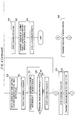
charge control device 16 will be described with reference to a flowchart ofFIG. 4 . In the following example, a description will be given of a case in which thepower supply 2 is connected to the firstpower receiving connector 1402 of thevehicle 10 during parking, and the charging schedule is conducted by the aid of themobile device 20. Also, in this embodiment, it is assumed that the time zone of the late-night electric power is 23:00 to 8:00 the next day. Theremote controller ECU 30 determines whether thepower supply 2 has been connected to the firstpower receiving connector 1402 through thebattery charger 14, or not (Step S10) . If no in Step S100, the operation is returned to Step S10. If yes in Step S10, theremote controller ECU 30 determines whether thecommunication part 32 has received the charging wait period setting instruction and the charging period setting instruction from themobile device 20, or not (Step S12). If no in Step S12, the operation is returned to Step S12. If yes in Step S12, theremote controller ECU 30 determines whether the charging enable conditions are satisfied, or not (Step S14, charging enabledetermination unit 30A) . If no in Step S14, theremote controller ECU 30 transmits an error message indicative of why the charging enable conditions are not satisfied from thecommunication part 32 to themobile device 20. Then, theremote controller ECU 30 allows thedisplay part 20C of themobile device 20 to display a fact that the charging schedule is disabled, and an error code or an error message (Step S48), and returns the operation to Step S10. The types of the error code or the error message are exemplified as follows. - 1) A connection between the first
power receiving connector 1402 of thebattery charger 14 and thepower supply 2 is canceled. - 2) The
IG switch 34 is at any position except for the OFF position. - 3) The shift position is at any position except for P (parking).
- 4) Abnormality is detected in at least one of the EV-
ECU 24, thecharge ECU 26, and theremote controller ECU 30. - If yes in Step S14, the
remote controller ECU 30 transmits a response indicative of reception of the charging wait period setting instruction and the charging period setting instruction from thecommunication part 32 to the remote controller ECU 30 (Step S16). Upon receiving the response, themobile ECU 20A of theremote controller ECU 30 clears a charging wait periodupdate request flag 2002 and a charging periodupdate request flag 2004. The charging wait period setting instruction received by theremote controller ECU 30 includes the charging wait period update request flag 2002 (set state) indicating that the charging wait period TA is updated, and the charging wait period TA. Also, the charging period setting instruction received by theremote controller ECU 30 includes the charging period update request flag 2004 (set state) indicating that the charging period TB is updated, and the charging period TB. Accordingly, theremote controller ECU 30 sets the received charging wait period TA for the chargingwait timer 30B, sets the received charging period TB for thecharging period timer 30E, and stores the charging period TB in the chargingperiod storage unit 30G (Step S18). Then, theremote controller ECU 30 sets the charging waittimer setting flag 30C and the charging periodtimer setting flag 30F, respectively (Step S20). - Then, the charging
wait timer 30B starts the first timing operation (Step S22). In this embodiment, a description will be given assuming that the charging wait period TA = 3 hours, the charging period TB = 9 hours, and a time at which the first timing operation starts is 20 : 00 as illustrated inFIG. 7A . Theremote controller ECU 30 transmits data of the remaining charging wait period T1 timed by the chargingwait timer 30B from thecommunication part 32 to themobile device 20 every predetermined period (Step S24:period annunciation unit 30J) . On the other hand, themobile ECU 20A allows the remaining charging wait period T1 received by thecommunication part 20B to be digitally displayed on thedisplay part 20C in real time, and also allows the charging period TB to be digitally displayed on thedisplay part 20C. Accordingly, the user can confirm the charging period TB, and can know the remaining charging wait period T1 in real time. Because there is a limit to the number of segments in thedisplay part 20C, the remaining charging wait period T1 and the charging period TB are switchingly displayed. - In this example, because display in the mobile device is not time information but period information, the display becomes OO.O period, and is smaller in the number of display segments than the display such as 00:00 using the time display, which is favorable for a reduction in the size and costs of the mobile device.
- Then, the
remote controller ECU 30 determines whether the remaining charging wait period T1 has become zero, or not (Step S26: chargingstart unit 30D) . If no in Step S26, the operation returns to Step S24. If yes in step S26, theremote controller ECU 30 allows thebattery charger 14 to start the operation of charging the travel battery 12 (Step S28: chargingstart unit 30D) . Further, theremote controller ECU 30 clears the charging waittimer setting flag 30C, and sets 24 hours for the chargingwait timer 30B (Step S30) . As a result, the chargingwait timer 30B again executes the timing operation from a state of the remaining charging wait period T1 = 24 hours. Also, the chargingperiod timer 30E starts the second timing operation (Step S32). That is, as illustrated inFIG. 7A , after the chargingwait timer 30B has terminated the operation of timing the charging wait period TA of 3 hours, the chargingperiod timer 30E starts the operation of timing the charging period TB of 9 hours. Also, the chargingwait timer 30B restarts the operation of timing the remaining charging wait period T1 = 24 hours from a time 23:00. In the figure, numerals surrounded by rectangular frames indicate the remaining charging period T2 timed by the timing operation restarted by the chargingwait timer 30B. Theremote controller ECU 30 transmits data of the remaining charging period T2 timed by the chargingperiod timer 30E from thecommunication part 32 to themobile device 20 every predetermined period (Step S34:period annunciation unit 30J) . On the other hand, the charging enabledetermination unit 30A allows the remaining charging period T2 received by thecommunication part 20B to be displayed on thedisplay part 20C in real time. Accordingly, the user can know the remaining charging period T2 in real time. In this case, because there is no need to display the charging wait period TA (or the remaining charging wait period T1), the charging wait period TA (or the remaining charging wait period T1) is not displayed (blanked) in thedisplay part 20C. - The
remote controller ECU 30 determines whether the control termination condition has been satisfied, or not (Step S36: force-quit unit 30I). If yes in Step S36, theremote controller ECU 30 allows thebattery charger 14 to stop the operation of charging the travel battery 12 (Step S50: force-quit unit 30I). Then, theremote controller ECU 30 transmits the code or message indicating the cause of stopping the charging operation from thecommunication part 32 to themobile device 20, and allows thedisplay part 20C of themobile device 20 to display a fact that the charging operation stops and the message (Step S52), and returns the operation to Step S10. The type of the code or message is identical with that of the error message described in the above-mentioned Step S48, or the code or message indicative of full charge of thetravel battery 12. If no in Step S36, theremote controller ECU 30 determines whether the remaining charging period T2 becomes zero, or not (Step S38: chargingstop unit 30H). If no in Step S38, the operation returns to Step S34. If yes in Step S38, theremote controller ECU 30 allows thebattery charger 14 to stop the operation of charging the travel battery 12 (Step S40: chargingstop unit 30H). As a result, as illustrated inFIG. 7A , the operation of charging thetravel battery 12 is terminated at 8 : 00 after the charging period TB of 9 hours. Also, at a time of 8: 00 when the charging operation has been terminated, the remaining charging wait period of the chargingwait timer 30B is 15 hours, and even after the charging operation has stopped, the timing operation of the chargingwait timer 30B is continuously executed. Then, theremote controller ECU 30 transmits a message indicating that the scheduled charging operation has been terminated from thecommunication part 32 to themobile device 20, and allows thedisplay part 20C of themobile device 20 to display the code or message that the scheduled charging operation has been terminated (Step S42). In this case, because there is no need to display the charging wait period TA (remaining charging wait period T1), the charging wait period TA is not displayed (blanked), and the charging period TB (remaining charging period T2) holds 0-hours display in the sense that the charging termination is displayed. - In this example, the
remote controller ECU 30 stores the present charging period TB in the chargingperiod storage unit 30G as "charging period data" for setting a subsequent charging schedule as described above (Step S44) . In this way, a series of scheduled charging operation is terminated. At a time of terminating the scheduled charging operation, a state in which the charging periodtimer setting flag 30F is set in Step S20 is maintained, and a state in which the charging waittimer setting flag 30C is cleared in Step S30 is maintained. - A case in which after the
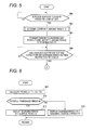
vehicle 10 travels by the aid of thetravel battery 12 that has been charged according to the schedule as described above, the scheduled charging operation is again conducted will be described with reference to flowcharts ofFIGS. 5 and 6 . In this example, as illustrated inFIG. 7B , a description will be given of a case in which thepower supply 2 is connected to the firstpower receiving connector 1402 for conducting the scheduled charging operation at a time 19:00 earlier by one hour than a time 20:00 which is the start time of the previous scheduled charging operation. As illustrated inFIG. 5 , theremote controller ECU 30 determines whether thepower supply 2 has been connected to the firstpower receiving connector 1402 through thebattery charger 14, or not (Step S60). If no in Step S60, the operation returns to Step S60. If yes in Step S60, theremote controller ECU 30 determines the display charging period T3 to be transmitted to the mobile device 20 (Step S62: display chargingperiod determination unit 30K). The display charging period T3 represents a charging period during which the scheduled charging operation is enabled. - A sub-routine in Step S62 will be described with reference to
FIG. 6 . Theremote controller ECU 30 calculates the time A = the charging wait period T1 - (24 - the charging period TB) (Step S68). A period A is a period used for calculating a period during which the charging operation is enabled when the charging termination time in the previously executed charging operation is fixed, and the charging period is set with the previously set charging period TB as an upper limit. Then, theremote controller ECU 30 determines whether period A > threshold period B (B is a predetermined threshold period shorter than the charging period TB) is satisfied, or not (Step S70). If yes in Step S70, theremote controller ECU 30 determines the above period A as the display charging period T3 (Step S72). That is, strictly, if the period A > 0 is satisfied, the period A becomes the charging period that can be realized at a time when the period A > 0 has been satisfied. However, if the period A is too short, the charging operation cannot be substantially executed. Therefore, a period during which the charging operation may be sufficiently conducted as the threshold period B, for example, 0.5 hours as the threshold period B are determined. If the period A is larger than the threshold period B, the period A is determined as the display charging period T3. If no in Step S79, that is, if the period A > the threshold period B is not satisfied, theremote controller ECU 30 determines the charging period TB set as the charging period according to the charging period setting instruction in conducting the previous scheduled charging operation as the display charging period T3 (Step S74). The previously set charging period TB is stored in the chargingperiod storage unit 30G. If period A > threshold period B is not satisfied, there are two cases of threshold period B ≥ period A > 0 and period A < 0, and the following respective processing is conducted. - 1) In a case of threshold period B ≥ period A > 0, the period A is too short, and the charging operation cannot be substantially executed. Accordingly, the charging period during which the previous scheduled charging operation can be realized is the previously set charging period TB, and the charging period TB is determined as the display charging period T3.
- 2) In a case of period A < 0, because a time when period A < 0 is before the start time of the previously set charging period TB, the realizable charging period in this case is the previously set charging period TB, and the charging period TB is determined as the display charging period T3.
- If the display charging period T3 is determined, the operation returns to
FIG. 5 , and theremote controller ECU 30 transmits the remaining charging wait period T1 and the display charging period T3 to themobile device 20 through the communication part 32 (Step S64: display chargingperiod determination unit 30K). If the display charging period T3 is smaller than the charging period TB, since theremote controller ECU 30 starts the charging operation without waiting for the charging operation (the charging wait period TA is zero), theremote controller ECU 30 transmits the remaining charging wait period T1 as zero. On the other hand, themobile ECU 20A of themobile device 20 allows thedisplay part 20C to display the received remaining charging wait period T1 as the charging period TB. The user determines the charging wait period TA and the charging period TB as they are, which are displayed by operating theoperation part 20D, if the charging wait period TA and the charging period TB, which are displayed at that time, are acceptable. As a result, the charging wait period setting instruction and the charging period setting instruction are transmitted from thecommunication part 20B of themobile device 20. Also, if the user intends to change the charging wait period TA and the charging period TB, which are displayed at this time, the user operates theoperation part 20D to change and determine the charging wait period TA and the charging period TB. As a result, the charging wait period setting instruction and the charging period setting instruction are transmitted from thecommunication part 20B of themobile device 20. Then, theremote controller ECU 30 determines whether thecommunication part 32 has received the charging wait period setting instruction and the charging period setting instruction from themobile device 20, or not (Step s66). If no in Step S66, the operation returns to Step S66. If yes in Step s66, the operation is shifted to Step S14 ofFIG. 4 , and the same processing is subsequently executed. - The operation will be described in detail with reference to
FIGS. 7B and 7C. FIG. 7B illustrates a case in which thepower supply 2 is connected to the firstpower receiving connector 1402 at a time 19:00 earlier by one hour than a time 20: 00 which is the start time of the previous scheduled charging operation. For that reason, 4 hours is displayed as the charging wait period TA on thedisplay part 20C of themobile device 20, and 9 hours that are identical with those in the previous operation are displayed as the charging period TB. That is, because the remaining charging wait period T1 = 4 hours, and the charging period TB = 9 hours, the period A = the remaining charging wait period T1 - (24 - the charging period TB) = 4 - (29-9) = -19 hours < 0 is satisfied. Therefore, the charging period TB is determined as the display charging period T3, and the charging period TB is displayed on thedisplay part 20C of themobile device 20 as a new chargeable charging period TB. Accordingly, if the user determines the charging wait period TA and the charging period TB without any change at this time, after the charging wait is conducted for 4 hours, the charging operation is conducted for 9 hours. - Also,
FIG. 7C illustrates a case in which thepower supply 2 is connected to the firstpower receiving connector 1402 at a time 2:00 the next data later by 6 hours than a time 20:00 which is the start time of the previous scheduled charging operation. In this case, because it runs over the time 23:00 which is the previous charging operation start time by 3 hours, zero is displayed as the charging wait period TA, and 6 hours obtained by subtracting 3 hours from 9 hours are displayed as the charging period TB, on thedisplay part 20C of themobile device 20. That is, because the remaining charging wait period T1 = 21 hours, and the previous charging period TB = 9 hours, the time A = the remaining charging wait period T1 - (24 - the charging period TB) = 21 - (24 - 9) = 6 hours > B is satisfied. Therefore, the time A = 6 hours is determined as the display charging period T3, and 6 hours are displayed on thedisplay part 20C of themobile device 20 as a new chargeable charging period TB. Accordingly, if the user determines the charging period TB = A = 6 hours without any change at this time, the charging operation immediately starts, and the charging operation is conducted for 6 hours. - As has been described above, according to the
charge control device 16 of this embodiment, the charging wait period TA and the charging period TB are set for the chargingwait timer 30B and thecharging period timer 30E by themobile device 20, respectively. If the charging enable conditions are satisfied, the timing operation of the chargingwait timer 30B and the second timing operation of thecharging period timer 30E are conducted whereby the operation of charging thetravel battery 12 is executed for the charging period TB after waiting for the charging wait period TA. - Accordingly, because the start time and the termination time of the charging operation are substantially defined by the charging wait period TA and the charging period TB, the charging operation can be surely implemented within the predetermined time zone. Further, this configuration is favorable for adequately conducting the charging operation by the aid of the cheap electric power such as a late-night electric power, and also favorable for the cost performance since setting is conducted by not time but period to reduce the amount of information.
- Also, in this embodiment, there is provided the
period annunciation unit 30J that transmits the remaining charging wait period T1 and the remaining charging period T2 to themobile device 20 via thecommunication part 32. Therefore, the remaining charging wait period T1 and the remaining charging period T2 can be confirmed in themobile device 20, which is favorable for proper provision of information on the scheduled charging operation of thetravel battery 12 to the user. Since management is conducted by period information, the display area on the mobile device can be reduced. - Further, in this embodiment, the charging period during which the charging operation can be conducted by the scheduled charging operation is determined as the display charging period T3 by the display charging
period determination unit 30K, and transmitted to themobile device 20. This configuration is favorable for proper provision of information on the scheduled charging operation of thetravel battery 12 to the user. - According to an aspect of the invention, because the start time and the termination time of the charging operation are substantially set by transmission of the charging wait period and the charging period from a mobile device, the charging operation can be surely implemented within the predetermined time zone. Further, this configuration is favorable for adequately conducting the charging operation, and also favorable for the cost performance since setting is conducted by not time but period to reduce the amount of information.
Claims (5)
- A charge control device that is mounted in an electric vehicle including a travel battery, which supplies an electric power to a travel driving source, and a battery charger, which executes charging operation for charging the travel battery by using a power supply, the charge control device comprising:a communication unit that receives a first instruction for setting a charging wait period, which is a period for waiting the charging operation by the battery charger, and a second instruction for setting a charging period, which is a period for executing the charging operation, the first instruction and the second instruction being transmitted from a mobile device;a first timing unit that starts first timing operation for calculating a remaining charging wait period, which is a remaining period of the charging wait period, by subtracting an elapsed period from the charging wait period;a charging start unit that allows the battery charger to start the charging operation when the remaining charging wait period becomes zero;a second timing unit that starts second timing operation, together with start of the charging operation, for calculating a remaining charging period, which is a remaining period of the charging period, by subtracting an elapsed period from the charging period; anda charging stop unit that allows the battery charger to stop the charging operation when the remaining charging period becomes zero.
- The charge control device according to claim 1 further comprising:a period annunciation unit that transmits the remaining charging wait period and the remaining charge period to the mobile device through the communication unit to allow the mobile device to display the remaining charging wait period and the remaining charge period.
- The charge control device according to claim 1 or claim 2 further comprising:a determination unit that determines a first period as a display charging period if A > B is satisfied when A = T1 - (24 - TB) , where A is the first period, B is a threshold period shorter than the charging period, T1 is the remaining charging wait period, and TB is the charging period, the determination unit that transmits the display charging period to the mobile device through the communication unit.
- The charge control device according to claim 3, wherein
the charging period is set in a scheduled charging operation, and
the display charging period determination unit determines a charging period, which is set in previous scheduled charging operation, as the display charging period if A > B is not satisfied. - The charge control device according to any one of claims 1 to 4, wherein
the power supply is a power supply supplied from an outlet provided in housing.
Applications Claiming Priority (1)
| Application Number | Priority Date | Filing Date | Title |
|---|---|---|---|
| JP2010188285A JP5369067B2 (en) | 2010-08-25 | 2010-08-25 | Charge control device |
Publications (2)
| Publication Number | Publication Date |
|---|---|
| EP2423031A2 true EP2423031A2 (en) | 2012-02-29 |
| EP2423031A3 EP2423031A3 (en) | 2013-05-15 |
Family
ID=52998386
Family Applications (1)
| Application Number | Title | Priority Date | Filing Date |
|---|---|---|---|
| EP20110178484 Withdrawn EP2423031A3 (en) | 2010-08-25 | 2011-08-23 | Charge control device |
Country Status (4)
| Country | Link |
|---|---|
| US (1) | US8854006B2 (en) |
| EP (1) | EP2423031A3 (en) |
| JP (1) | JP5369067B2 (en) |
| CN (1) | CN102386643B (en) |
Families Citing this family (21)
| Publication number | Priority date | Publication date | Assignee | Title |
|---|---|---|---|---|
| US9399402B2 (en) | 2011-04-21 | 2016-07-26 | Lear Corporation | Proximity detection circuit for on-board vehicle charger |
| US9211798B2 (en) | 2011-07-28 | 2015-12-15 | Lear Corporation | Multistage power supply system and method for providing uninterrupted power to vehicle circuitry |
| US9348381B2 (en) | 2011-10-19 | 2016-05-24 | Zeco Systems Pte Ltd | Methods and apparatuses for charging of electric vehicles |
| US8749198B2 (en) * | 2011-11-10 | 2014-06-10 | Lear Corporation | Control pilot detection circuit |
| US9233611B2 (en) | 2011-11-10 | 2016-01-12 | Lear Corporation | Proximity detection circuit having short protection |
| US9440538B2 (en) | 2011-11-11 | 2016-09-13 | Lear Corporation | Housekeeping circuit having trickle charge capabilities |
| CN104204830B (en) | 2012-01-19 | 2018-03-09 | 耐克创新有限合伙公司 | Activity monitoring device and its power management method |
| JP5773055B2 (en) * | 2012-02-22 | 2015-09-02 | トヨタ自動車株式会社 | Vehicle, charging device and charging system |
| CN104756348A (en) * | 2012-03-20 | 2015-07-01 | 奥克兰联合服务有限公司 | Wiring Harnesses and Wireless Power Transfer Systems |
| US20130264998A1 (en) * | 2012-04-10 | 2013-10-10 | Imation Corp. | Smart charger for personal media devices |
| KR101925933B1 (en) * | 2012-11-14 | 2018-12-06 | 삼성에스디아이 주식회사 | Method and apparatus for controlling charging of secondary battery |
| JP5958424B2 (en) * | 2013-06-11 | 2016-08-02 | 株式会社豊田自動織機 | Secondary battery charging start control method and charging device |
| CN103682498B (en) * | 2013-12-04 | 2016-03-02 | 华为终端有限公司 | A kind of charging method and electronic equipment |
| KR101838506B1 (en) | 2015-11-09 | 2018-03-14 | 현대자동차주식회사 | Vehicle and method of recharging battery therein |
| CN106183877B (en) * | 2016-08-27 | 2020-06-23 | 许继电气股份有限公司 | Cross-operating platform charging method for electric vehicles |
| CN106965699B (en) * | 2017-04-28 | 2019-05-14 | 北京新能源汽车股份有限公司 | Charging control method and device for electric automobile, vehicle-mounted communication box and electric automobile |
| JP7380272B2 (en) * | 2020-02-04 | 2023-11-15 | トヨタ自動車株式会社 | vehicle |
| US20210270077A1 (en) * | 2020-03-02 | 2021-09-02 | Hall Labs Llc | Battery system for powering an overhead door opener |
| JP7436317B2 (en) * | 2020-07-29 | 2024-02-21 | 日立建機株式会社 | electric working machine |
| KR102206891B1 (en) * | 2020-09-01 | 2021-01-27 | (주)대성지이-쓰리 | Electric Vehicle Diagnostic System Training Equipment |
| CN116373625B (en) * | 2023-04-04 | 2025-12-05 | 上汽通用五菱汽车股份有限公司 | An electronic timing processing method and system for scheduled charging of new energy vehicles |
Citations (3)
| Publication number | Priority date | Publication date | Assignee | Title |
|---|---|---|---|---|
| JPH03104046U (en) * | 1990-02-05 | 1991-10-29 | ||
| JPH11266509A (en) * | 1998-03-16 | 1999-09-28 | Park 24 Co Ltd | Electric vehicle charger |
| JP2010142026A (en) | 2008-12-11 | 2010-06-24 | Mitsubishi Motors Corp | Charger device for electric vehicle |
Family Cites Families (10)
| Publication number | Priority date | Publication date | Assignee | Title |
|---|---|---|---|---|
| JP2785316B2 (en) * | 1989-04-19 | 1998-08-13 | 株式会社豊田自動織機製作所 | Charger |
| JPH03104046A (en) | 1989-09-18 | 1991-05-01 | Hitachi Ltd | Command execution control system |
| JP3216133B2 (en) * | 1990-11-13 | 2001-10-09 | ソニー株式会社 | Non-aqueous electrolyte secondary battery charging method |
| JPH077866A (en) * | 1993-06-16 | 1995-01-10 | Sanyo Electric Co Ltd | Rechargeable battery charging circuit |
| JP3178171B2 (en) * | 1993-07-27 | 2001-06-18 | トヨタ自動車株式会社 | In-car charger display device |
| JP3554057B2 (en) | 1995-02-06 | 2004-08-11 | 本田技研工業株式会社 | Battery charging control device for electric vehicles |
| JP4642185B2 (en) * | 2000-06-16 | 2011-03-02 | ソニー株式会社 | battery pack |
| JPWO2009075313A1 (en) | 2007-12-13 | 2011-04-28 | トヨタ自動車株式会社 | Electricity amount calculation device, fee calculation device and fee calculation method for calculating fee for power consumption, vehicle information output device and information output method |
| JP2010104114A (en) * | 2008-10-22 | 2010-05-06 | Toyota Motor Corp | Vehicle control apparatus and vehicle |
| JP2010142025A (en) * | 2008-12-11 | 2010-06-24 | Mitsubishi Motors Corp | Electric vehicle charging device |
-
2010
- 2010-08-25 JP JP2010188285A patent/JP5369067B2/en active Active
-
2011
- 2011-08-22 US US13/214,796 patent/US8854006B2/en active Active
- 2011-08-23 EP EP20110178484 patent/EP2423031A3/en not_active Withdrawn
- 2011-08-25 CN CN201110245383.5A patent/CN102386643B/en active Active
Patent Citations (3)
| Publication number | Priority date | Publication date | Assignee | Title |
|---|---|---|---|---|
| JPH03104046U (en) * | 1990-02-05 | 1991-10-29 | ||
| JPH11266509A (en) * | 1998-03-16 | 1999-09-28 | Park 24 Co Ltd | Electric vehicle charger |
| JP2010142026A (en) | 2008-12-11 | 2010-06-24 | Mitsubishi Motors Corp | Charger device for electric vehicle |
Also Published As
| Publication number | Publication date |
|---|---|
| JP5369067B2 (en) | 2013-12-18 |
| CN102386643B (en) | 2014-12-10 |
| JP2012050197A (en) | 2012-03-08 |
| US8854006B2 (en) | 2014-10-07 |
| EP2423031A3 (en) | 2013-05-15 |
| CN102386643A (en) | 2012-03-21 |
| US20120049796A1 (en) | 2012-03-01 |
Similar Documents
| Publication | Publication Date | Title |
|---|---|---|
| EP2423031A2 (en) | Charge control device | |
| US10828996B2 (en) | On-board unit and electric vehicle management system | |
| US11230204B2 (en) | Power management apparatus, power management system, and power management method | |
| JP5483014B2 (en) | Control device | |
| US20140074320A1 (en) | Vehicle remote control system, remote control terminal, server, and vehicle | |
| KR102564020B1 (en) | Apparatus and method for providing update of vehicle | |
| CN109591647B (en) | Control method and device for charging of electric automobile and automobile | |
| JP7329555B2 (en) | Charging control device, moving object, charging control system, and charging control method | |
| JP7198851B2 (en) | Electric vehicle charge control method and electric vehicle | |
| JP2023146721A (en) | Charging management system | |
| JP5919637B2 (en) | Vehicle plug-in charging system and charging condition setting management device | |
| CN111391712A (en) | Charging management method, device, equipment and computer readable storage medium | |
| CN116331008A (en) | Parking system, vehicle, vehicle charging system and vehicle charging method | |
| EP4375117A1 (en) | Display device and method | |
| JP5704203B2 (en) | Charge control device | |
| CN112440802A (en) | Vehicle charging system, method, device, vehicle and storage medium | |
| JP5633614B2 (en) | Charge control device | |
| US20250222813A1 (en) | Vehicle charging system | |
| JP2017085841A (en) | Charge control device | |
| CN115431814B (en) | Vehicle charging method and device | |
| JP2024017267A (en) | Charging control system | |
| CN120348190A (en) | Management system | |
| JP2022147843A (en) | charging management system | |
| JP2023007098A (en) | Control device and control system |
Legal Events
| Date | Code | Title | Description |
|---|---|---|---|
| 17P | Request for examination filed |
Effective date: 20110921 |
|
| AK | Designated contracting states |
Kind code of ref document: A2 Designated state(s): AL AT BE BG CH CY CZ DE DK EE ES FI FR GB GR HR HU IE IS IT LI LT LU LV MC MK MT NL NO PL PT RO RS SE SI SK SM TR |
|
| AX | Request for extension of the european patent |
Extension state: BA ME |
|
| PUAI | Public reference made under article 153(3) epc to a published international application that has entered the european phase |
Free format text: ORIGINAL CODE: 0009012 |
|
| PUAL | Search report despatched |
Free format text: ORIGINAL CODE: 0009013 |
|
| AK | Designated contracting states |
Kind code of ref document: A3 Designated state(s): AL AT BE BG CH CY CZ DE DK EE ES FI FR GB GR HR HU IE IS IT LI LT LU LV MC MK MT NL NO PL PT RO RS SE SI SK SM TR |
|
| AX | Request for extension of the european patent |
Extension state: BA ME |
|
| RIC1 | Information provided on ipc code assigned before grant |
Ipc: B60L 11/18 20060101ALI20130405BHEP Ipc: H02J 7/00 20060101AFI20130405BHEP |
|
| 17Q | First examination report despatched |
Effective date: 20171212 |
|
| RAP1 | Party data changed (applicant data changed or rights of an application transferred) |
Owner name: MITSUBISHI JIDOSHA KOGYO KABUSHIKI KAISHA |
|
| STAA | Information on the status of an ep patent application or granted ep patent |
Free format text: STATUS: THE APPLICATION IS DEEMED TO BE WITHDRAWN |
|
| 18D | Application deemed to be withdrawn |
Effective date: 20200820 |