EP2422244B1 - Commande de sécurité et procédé de commande d'une installation automatisée - Google Patents
Commande de sécurité et procédé de commande d'une installation automatisée Download PDFInfo
- Publication number
- EP2422244B1 EP2422244B1 EP20100718871 EP10718871A EP2422244B1 EP 2422244 B1 EP2422244 B1 EP 2422244B1 EP 20100718871 EP20100718871 EP 20100718871 EP 10718871 A EP10718871 A EP 10718871A EP 2422244 B1 EP2422244 B1 EP 2422244B1
- Authority
- EP
- European Patent Office
- Prior art keywords
- safety
- value
- processor
- fsv1a
- control unit
- Prior art date
- Legal status (The legal status is an assumption and is not a legal conclusion. Google has not performed a legal analysis and makes no representation as to the accuracy of the status listed.)
- Active
Links
- 238000000034 method Methods 0.000 title claims description 18
- 230000015654 memory Effects 0.000 claims description 144
- 238000012360 testing method Methods 0.000 claims description 79
- 238000012545 processing Methods 0.000 claims description 30
- 238000003860 storage Methods 0.000 claims description 19
- 238000004590 computer program Methods 0.000 claims description 2
- 238000009434 installation Methods 0.000 claims 4
- 230000006870 function Effects 0.000 description 10
- 230000008859 change Effects 0.000 description 7
- 230000008901 benefit Effects 0.000 description 5
- 230000008569 process Effects 0.000 description 5
- 230000007257 malfunction Effects 0.000 description 3
- 230000004044 response Effects 0.000 description 3
- 238000010200 validation analysis Methods 0.000 description 3
- 230000009471 action Effects 0.000 description 2
- 230000007175 bidirectional communication Effects 0.000 description 2
- 238000013461 design Methods 0.000 description 2
- 238000006243 chemical reaction Methods 0.000 description 1
- 230000006854 communication Effects 0.000 description 1
- 238000004891 communication Methods 0.000 description 1
- 238000010276 construction Methods 0.000 description 1
- 125000004122 cyclic group Chemical group 0.000 description 1
- 238000013500 data storage Methods 0.000 description 1
- 238000011161 development Methods 0.000 description 1
- 238000005516 engineering process Methods 0.000 description 1
- 238000011156 evaluation Methods 0.000 description 1
- 231100001261 hazardous Toxicity 0.000 description 1
- 238000002955 isolation Methods 0.000 description 1
- 230000000670 limiting effect Effects 0.000 description 1
- 238000003754 machining Methods 0.000 description 1
- 238000007726 management method Methods 0.000 description 1
- 238000004519 manufacturing process Methods 0.000 description 1
- 239000000463 material Substances 0.000 description 1
- 238000012806 monitoring device Methods 0.000 description 1
- 238000012544 monitoring process Methods 0.000 description 1
- 239000000178 monomer Substances 0.000 description 1
- 238000005457 optimization Methods 0.000 description 1
- 230000009897 systematic effect Effects 0.000 description 1
- 238000012546 transfer Methods 0.000 description 1
Images

Classifications
-
- G—PHYSICS
- G05—CONTROLLING; REGULATING
- G05B—CONTROL OR REGULATING SYSTEMS IN GENERAL; FUNCTIONAL ELEMENTS OF SUCH SYSTEMS; MONITORING OR TESTING ARRANGEMENTS FOR SUCH SYSTEMS OR ELEMENTS
- G05B9/00—Safety arrangements
- G05B9/02—Safety arrangements electric
- G05B9/03—Safety arrangements electric with multiple-channel loop, i.e. redundant control systems
-
- G—PHYSICS
- G05—CONTROLLING; REGULATING
- G05B—CONTROL OR REGULATING SYSTEMS IN GENERAL; FUNCTIONAL ELEMENTS OF SUCH SYSTEMS; MONITORING OR TESTING ARRANGEMENTS FOR SUCH SYSTEMS OR ELEMENTS
- G05B19/00—Programme-control systems
- G05B19/02—Programme-control systems electric
- G05B19/04—Programme control other than numerical control, i.e. in sequence controllers or logic controllers
- G05B19/05—Programmable logic controllers, e.g. simulating logic interconnections of signals according to ladder diagrams or function charts
- G05B19/058—Safety, monitoring
-
- G—PHYSICS
- G05—CONTROLLING; REGULATING
- G05B—CONTROL OR REGULATING SYSTEMS IN GENERAL; FUNCTIONAL ELEMENTS OF SUCH SYSTEMS; MONITORING OR TESTING ARRANGEMENTS FOR SUCH SYSTEMS OR ELEMENTS
- G05B2219/00—Program-control systems
- G05B2219/10—Plc systems
- G05B2219/14—Plc safety
- G05B2219/14006—Safety, monitoring in general
-
- G—PHYSICS
- G05—CONTROLLING; REGULATING
- G05B—CONTROL OR REGULATING SYSTEMS IN GENERAL; FUNCTIONAL ELEMENTS OF SUCH SYSTEMS; MONITORING OR TESTING ARRANGEMENTS FOR SUCH SYSTEMS OR ELEMENTS
- G05B2219/00—Program-control systems
- G05B2219/10—Plc systems
- G05B2219/14—Plc safety
- G05B2219/14012—Safety integrity level, safety integrated systems, SIL, SIS
-
- G—PHYSICS
- G05—CONTROLLING; REGULATING
- G05B—CONTROL OR REGULATING SYSTEMS IN GENERAL; FUNCTIONAL ELEMENTS OF SUCH SYSTEMS; MONITORING OR TESTING ARRANGEMENTS FOR SUCH SYSTEMS OR ELEMENTS
- G05B2219/00—Program-control systems
- G05B2219/20—Pc systems
- G05B2219/24—Pc safety
- G05B2219/24024—Safety, surveillance
-
- G—PHYSICS
- G05—CONTROLLING; REGULATING
- G05B—CONTROL OR REGULATING SYSTEMS IN GENERAL; FUNCTIONAL ELEMENTS OF SUCH SYSTEMS; MONITORING OR TESTING ARRANGEMENTS FOR SUCH SYSTEMS OR ELEMENTS
- G05B2219/00—Program-control systems
- G05B2219/20—Pc systems
- G05B2219/24—Pc safety
- G05B2219/24188—Redundant processors run different programs
-
- G—PHYSICS
- G06—COMPUTING; CALCULATING OR COUNTING
- G06F—ELECTRIC DIGITAL DATA PROCESSING
- G06F11/00—Error detection; Error correction; Monitoring
- G06F11/07—Responding to the occurrence of a fault, e.g. fault tolerance
- G06F11/08—Error detection or correction by redundancy in data representation, e.g. by using checking codes
- G06F11/10—Adding special bits or symbols to the coded information, e.g. parity check, casting out 9's or 11's
- G06F11/1076—Parity data used in redundant arrays of independent storages, e.g. in RAID systems
-
- G—PHYSICS
- G06—COMPUTING; CALCULATING OR COUNTING
- G06F—ELECTRIC DIGITAL DATA PROCESSING
- G06F11/00—Error detection; Error correction; Monitoring
- G06F11/07—Responding to the occurrence of a fault, e.g. fault tolerance
- G06F11/14—Error detection or correction of the data by redundancy in operation
- G06F11/1402—Saving, restoring, recovering or retrying
- G06F11/1415—Saving, restoring, recovering or retrying at system level
- G06F11/1417—Boot up procedures
-
- Y—GENERAL TAGGING OF NEW TECHNOLOGICAL DEVELOPMENTS; GENERAL TAGGING OF CROSS-SECTIONAL TECHNOLOGIES SPANNING OVER SEVERAL SECTIONS OF THE IPC; TECHNICAL SUBJECTS COVERED BY FORMER USPC CROSS-REFERENCE ART COLLECTIONS [XRACs] AND DIGESTS
- Y02—TECHNOLOGIES OR APPLICATIONS FOR MITIGATION OR ADAPTATION AGAINST CLIMATE CHANGE
- Y02P—CLIMATE CHANGE MITIGATION TECHNOLOGIES IN THE PRODUCTION OR PROCESSING OF GOODS
- Y02P90/00—Enabling technologies with a potential contribution to greenhouse gas [GHG] emissions mitigation
- Y02P90/02—Total factory control, e.g. smart factories, flexible manufacturing systems [FMS] or integrated manufacturing systems [IMS]
Definitions
- the present invention relates to a safety controller for controlling an automated system according to a user program running in the safety controller, the system comprising a plurality of sensors and a plurality of actuators, and wherein the user program comprises a plurality of control instructions for controlling the actuators, with a first A processor configured to process at least a portion of the control instructions by processing a plurality of first program variables with a second processor configured to process at least a portion of the control instructions by processing a plurality of second program variables, and a non-processor volatile data memory for storing non-volatile data which must be present when switching on the safety controller after a power failure.
- the invention further relates to a method of controlling an automated plant, the plant comprising a plurality of sensors and a plurality of actuators.
- a safety controller in the sense of the present invention is a device or a device which receives the input signals supplied by sensors and generates output signals therefrom by logic operations and possibly further signal or data processing steps. The output signals can then Actuators are supplied, which cause depending on the input signals actions or reactions in a controlled system.
- a preferred field of application for such safety controls is the monitoring of emergency stop buttons, two-hand controls, safety gates or light curtains in the field of machine safety.
- sensors are used, for example, to hedge a machine that poses a risk to people or material goods during operation.
- a signal is generated which is fed to the safety controller as an input signal.
- the safety controller then shuts down the hazardous part of the machine with the aid of an actuator, for example.
- Characteristic of a safety control is in contrast to a "normal" control that the safety control even if it or a device connected to it malfunction occurs, always ensures a safe state of dangerous equipment or machinery. Therefore, in safety control systems extremely high demands are placed on the own fault tolerance, which results in a considerable effort in the development and production.
- a safety control means a device or device which at least meets safety category 3 of the cited European standard EN 954-1 or whose safety integrity level (SIL) at least reaches level 2 according to the cited standard IEC 61508.
- a programmable safety controller offers the user the possibility of individually defining the logical operations and, if necessary, further signal or data processing steps with the aid of software, the so-called user program, according to his needs. This results in a great deal of flexibility compared to previous solutions, in which the logic operations were generated by a defined wiring between different safety modules.
- An application program can be created, for example, using a commercially available personal computer (PC) and using appropriately set up software programs.
- a safety controller In a safety control extremely high demands are made on the own fault safety, i. with regard to errors occurring in the safety control.
- One measure consists, for example, in designing a safety controller, at least in the data processing components, such as the processors, redundantly.
- the greatest possible availability of the safety control with regard to errors occurring in the safety control is achieved.
- high availability of a safety controller is desirable in view of errors possibly occurring outside of the safety controller. For example, after a power failure, a safety controller should continue to be operated without problem in the state that the safety controller was taking before the power failure. But especially with regard to the availability of errors occurring outside the safety control, safety controls are still not optimal.
- DE 198 02 728 Discloses a safety controller with a non-volatile data memory in which machine parameters MP are stored.
- the machine parameters should essentially remain unchanged over the entire service life of the machine or the controller.
- independent CRC checksums are calculated in redundant channels of the safety control and stored together with the machine parameters in the non-volatile data memory.
- the CRC checksums are cyclically checked at certain intervals, wherein a first processor calculates the first checksum and a second processor calculates the second checksum.
- DE 20 2006 016 012 U1 discloses a system architecture for firmware used in a safety-related device.
- the firmware has a first part, which is responsible for a safety-related evaluation, and a non-safe, application-specific part.
- the secure part and the application-specific part are stored separately in different memories and each secured with its own CRC checksum.
- safety-relevant input data and safety-relevant output data are saved with another CRC checksum. With the help of the CRC checksums, it should be ensured that when changing or executing the application-specific part no change of the safe part and no change of the safe input and output data takes place.
- a safety control of the aforementioned type wherein the first processor is configured to determine a first test value for at least one of the first program variables as a function of an instantaneous value available for that first program variable at a first defined instant, wherein the second processor is further adapted to determine a second test value corresponding to the first test value, and wherein the data memory is adapted to store the instantaneous value, the first test value and the second test value, wherein the safety controller is designed to validate the instantaneous value when it is restarted perform, wherein the safety controller is further configured to plausibilize the instantaneous value with the first test value by means of the first processor and to validate the instantaneous value with the second test value by means of the second processor.
- the new safety control and the new method is based on the idea, in a data memory for a program variable an instantaneous value and both a first test value, which is determined with a first processor and thus for a first channel of the safety controller, and a second test value, with a second processor and thus for a second channel is determined to store.
- a restart for example, after an unexpected interruption of the operation, the validity of the still stored instantaneous value can be checked redundantly for both channels.
- This increases the availability of the safety controller. Since both test values are stored in a data memory, it is sufficient to provide a data memory for only one of the two channels. It is not necessary to provide a separate data memory for each of the two channels. This reduces the cost of implementing a safety control.
- the safety controller is designed to carry out a validity check of the instantaneous value during the restart and to make the instantaneous value plausible with the first test value by means of the first processor and to validate the instantaneous value with the second test value by means of the second processor.
- This measure has the advantage that with only one instantaneous value, which is additionally determined for only one of the two channels, a validity check can be carried out for the two channels of a safety control. As a result, for example, the effort for saving the instantaneous value can be reduced. So it is sufficient to provide only a single data store.
- this data memory is assigned to that channel of the safety controller in which both safety-related program variables and non-safety-related program variables are processed.
- the second processor is further configured to determine the second test value as a function of an instantaneous value of one of the second program variables, the second program variable corresponding to the first program variable.
- the first and second program variables are mutually redundant program variables that represent a common instantaneous value of the controlled system.
- the two test values are determined independently and thus independently of each other. This makes the checking whether the stored instantaneous value is valid or not more reliable.
- a separate test value is available for each of the two channels. For both channels an independent validity check and plausibility check of the stored instantaneous value can be made. This redundancy increases the availability of the safety controller and thus the system to be controlled.
- the instantaneous value of the first program variables and the instantaneous value of the second program variable are present in the same task cycle.
- the processors cycle their respective control program, each processor polling its program variables cyclically.
- the first and second program variables come from a common cycle. They therefore represent two largely instantaneous instantaneous values. This measure ensures that the two instantaneous values correspond to one another in terms of time. They are therefore better comparable and it is sufficient to store only an instantaneous value for a validity check. This allows a cost-effective dimensioning of the data memory.
- the task cycle is advantageously defined by the first defined time.
- the safety controller is designed to determine the two test values diversified.
- This measure helps to increase the reliability of a validation.
- different algorithms are used for determining the respective test value for the two channels of a safety control.
- the data memory is designed as a non-volatile data memory.
- the data memory is preferably designed as a so-called magneto-resistive random access memory (MRAM) or as a ferroelectric random access memory (FRAM).
- MRAM magneto-resistive random access memory
- FRAM ferroelectric random access memory
- the safety controller is designed to repeatedly determine the two test values for successive times.
- This action ensures that the stored instantaneous value is refreshed repeatedly.
- the update occurs at regular time intervals.
- the design contributes advantageously to the fact that a restart of the system can be done each with quite current values. A restart of the system can therefore be easier and faster.
- the first processor is further configured to perform an instantaneous value comparison.
- the first processor compares instantaneous values of different times.
- This measure enables optimized storage the current instantaneous value and the two test values.
- the instantaneous value comparison is carried out to determine whether there is a change in the instantaneous value with respect to a previous, already stored torque value. If it is determined that there is no change, the current instantaneous value and the two current test values are not additionally stored again. In other words, storage advantageously takes place only when there is actually a change. As a result, a smaller data storage can be used, resulting in a cost savings.
- this measure causes an effort optimization. This measure results in the fact that an instantaneous value and associated test values are not stored for each task cycle.
- the data memory has two memory areas assigned to the first program variable.
- This measure makes it possible to store a current instantaneous value and the two associated test values for two different points in time and thus two different task cycles.
- a history of the instantaneous value is preferably stored in the memory areas via at least two different task cycles. This further increases the availability of the system to be controlled on a restart. If during the validity check it is determined that the most recently saved, current instantaneous value is not valid and can therefore not be used for the initialization of the safety controller, a previously stored, older instantaneous value is still available which can be advantageously used for the restart.
- the safety controller is designed to store the instantaneous value and the two test values alternately in the two memory areas.
- This embodiment uses two memory areas to alternately update the history of the current value. At any given time, the embodiment keeps a current instantaneous value (from the current task cycle Z) in the one memory area and an older instantaneous value (from the previous one) Task cycle Z-1) in the other memory area. If now in the next task cycle Z + 1 a current instantaneous value is read, this embodiment overwrites the oldest stored instantaneous value. This embodiment ensures that, during operation of the safety control system, the two most recent generations of instantaneous values are always stored with a minimum of memory requirement and are therefore available for initialization of the safety control system after an interruption.
- At least one of the two processors is designed to determine a value for a write counter.
- the write counter represents which of the two previously mentioned memory areas contains the respectively most recent instantaneous value.
- the first processor is further configured to determine the first test value as a function of the instantaneous value and the value of the write counter.
- the first processor not only takes into account the instantaneous value, but also the write counter value when determining the checksum.
- the first check value is determined as follows: the current value and the value of the write counter are stored in two memory cells of a memory area. The first test value is then determined via the values in the two memory cells.
- the embodiment has the advantage that the test value both the instantaneous value as well as its actuality, which further increases the reliability of the information when the system is restarted.
- first and the second program variables are each safety-relevant program variables.
- zero-voltage-safe data are essentially security-relevant data. These can be instantaneous values of safety-related program input variables, instantaneous values of safety-related program output variables or instantaneous values of safety-relevant program intermediate variables. In short, it can be data that occurs when processing security-related control instructions.
- non-safety-relevant data that arises when processing non-safety-relevant control instructions, ie instantaneous values of non-safety-relevant program input variables, instantaneous value of non-safety-relevant program output variables or instantaneous values of non-safety-related program intermediate variables.
- non-safety-relevant data can be important for a system startup.
- An example of this is a non-safety-relevant counter variable whose instantaneous value represents the number of chairs in a chairlift that are no longer on the transport rope but are already in a storage depot.
- the first processor may be configured to determine a first test value for any number of first program variables.
- the second processor may be configured to determine a corresponding second test value for each of the first test values.
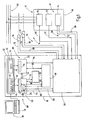
- Fig. 1 is a safety controller designated by the reference numeral 10.
- the safety controller 10 is designed to control an automated system designated in its entirety by the reference numeral 12.
- the system 12 comprises a multiplicity of actuators 14 and a plurality of sensors 16.
- a consumer 18 contained in the system 12 is shown, which may be, for example, a robot
- the safety controller 10 has a dual-channel redundant structure in order to achieve the required fault tolerance for controlling safety-critical applications or processes. Representing the two-channel construction are in Fig. 1 two from each other separate processors, namely a first processor 20 and a second processor 22, shown.
- the two processors 20, 22 are connected via a bidirectional communication interface 24 to each other to monitor each other and to be able to exchange data.
- the two channels of the safety controller 10 and the two processors 20, 22 diversified, ie different from each other, constructed to largely rule out systematic errors.
- Reference numeral 26 denotes an input / output unit which is in communication with each of the two processors 20, 22.
- the input / output unit 26 receives control input signals 28 from the sensors 16 and forwards them in an adapted data format to each of the two processors 20, 22 on. Furthermore, the input / output unit 26 generates control output signals 30 in response to the processors 20, 22 with which the actuators 14 are actuated.
- the reference numeral 32 denotes a program memory in which a user program 34 is stored in the form of machine code.
- the user program 34 is processed by the safety controller 10.
- the user program 34 is created with the aid of a programming tool, with a source code first being created, which is then converted into a machine code.
- the programming tool is, for example, a computer program 36 that can be executed on a conventional PC 38.
- the program memory 32 is preferably designed as an SD card or as a CF card. This allows a simple replacement of the user program 34 without direct connection to the PC 38.
- the user program 34 may be stored in a built-in the safety controller 10 memory, such as an EEPROM. In any case, the program memory 32 is executed zero voltage safe.
- a first machine code 40 and a second machine code 42 are stored in the program memory 32.
- the first machine code 40 is for the first processor 20 and the second machine code 42 is for the second processor 22.
- the first machine code 40 comprises a first security code 44 and a standard code 46.
- the first security code 44 includes those security control instructions which are to be processed by the first processor 20 within the scope of the security tasks to be performed by the security controller 10.
- the standard code 46 includes those standard control instructions that are to be processed by the first processor 20 as part of the standard tasks to be performed by the safety controller 10.
- the second machine code 42 includes a second security code 48 that includes those security control instructions to be processed by the second processor 22.
- the safety control instructions and standard control instructions are collectively referred to herein as control instructions.
- a first current safety control instruction 50 and, secondly, a current standard control instruction 52 are processed in the first processor 20 on the one hand.
- a second current safety control instruction 54 is processed in the second processor 22.
- first non-safety-related data 56 are exchanged between the first processor 20 and the input / output unit 26.
- instantaneous values of non-safety-relevant control input signals 58 which are generated by non-safety-relevant sensors 60, are fed to the first processor 20 using non-safety-related program input variables.
- the non-safety-related sensors 60 are sensors whose signals are primarily of importance for the operation of the plant, of which, however, in the event of an error, no immediate danger to life and limb. For example, non-safety-related sensors detect the position of a tool for machining a workpiece.
- the non-safety-relevant sensors 60 are generally formed non-failsafe.
- the input / output unit 26 is made using non-safety related program output variables
- Instantaneous values of non-safety-related control output signals 62 supplied to the non-safety-related actuators 64 are fed to their control.
- the non-safety-related actuators 64 may be, for example, motors or actuating cylinders.
- the instantaneous values of the non-safety-relevant control output signals 62 are determined as a function of the non-safety-relevant control input signals 58 in accordance with the standard control instructions. In this case, it may be necessary to determine intermediate variables whose instantaneous values are assigned to non-safety-relevant program intermediate variables.
- the instantaneous values of the non-safety-related program intermediate variables are supplied to a main memory 68 by means of second non-safety-relevant data 66 and stored there temporarily.
- first safety-relevant data 70 are exchanged between the first processor 20 and the input / output unit 26.
- the first processor 20 is supplied with safety-relevant program input variables using instantaneous values of safety-related control input signals 72, which are generated by safety-relevant sensors 74.
- the safety-related sensors 74 are, for example, emergency stop buttons, safety door switches, light grids, speed monitoring devices or other sensors for recording safety-relevant parameters.
- the input / output unit 26 is supplied using safety-relevant program output variables instantaneous values of safety-related control output signals 76, the safety-related actuators 78 are supplied to their control.
- the safety-related actuators 78 are, for example, contactors whose normally open contacts are arranged in the connection between a power supply 80 and the load 18 to safety-relevant solenoid valves or other actuators with which a dangerous drive can be shut down reliably.
- the power supply 80 of the consumer 18 can be switched off, whereby it is possible to transfer at least the consumer 18 in a safe state when a corresponding malfunction occurs.
- the instantaneous values of the safety relevant Control output signals 76 are determined in response to the safety-relevant control input signals 72 in accordance with the safety control instructions. In this case, it may be necessary to determine safety-relevant intermediate variables whose instantaneous values are assigned to safety-relevant program intermediate variables.
- the instantaneous values of the safety-related program intermediate variables are supplied to the main memory 68 by means of second safety-relevant data 82 and stored there temporarily.
- the procedure according to the first current safety control instruction 50 As part of the processing of the second current safety control instruction 54, which is a safety-relevant control instruction, the procedure according to the first current safety control instruction 50.
- third security-relevant data 84 corresponding to the first security-relevant data 70 and fourth security-relevant data 86 corresponding to the second security-relevant data 82 are used in a corresponding manner.
- the first processor 20 is thus designed to process at least a part of the control instructions of the user program by logical links of a multiplicity of first program variables.
- the first processor 20 is part of a first channel 88, referred to as channel A.
- the second processor 22 is thus designed to process at least part of the control instructions of the user program by processing a plurality of second program variables.
- the second processor 22 is part of a second channel 90, referred to as channel B.
- a data memory 92 is present in the safety controller 10.
- These zero-voltage-safe data are those data which, for example, must be present when the safety controller 10 is switched on after a power failure and thus the start-up of the system 12 to be controlled.
- This data memory is designed as a non-volatile data memory.
- the data memory 92 is assigned to the first processor 20, that is to say the processor which has both safety control instructions as well Standard control statements processed. This has the advantage that security-relevant data and non-security-relevant data, which are processed by the first processor 20, can be stored in the data memory 92 in a simple manner.
- Security-relevant data that is processed in the second processor 22 and is to be stored in the data memory 92 are supplied to the first processor 20 via the bidirectional communication interface 24 for writing to the data memory 92.
- the second processor 22 receives data stored in the data memory 92 back.
- the assignment of the data memory 92 to the first processor 20 is not intended to be restrictive. It is also conceivable to associate the data memory 92 with the second processor 22. It is also conceivable that both processors 20, 22 can access the data memory 92 directly.
- the writing of data into the data memory 92 is indicated by an arrow 94 and the reading out of data from the data memory 92 is shown by an arrow 96.
- Which data is actually written in the data memory 92 and thus stored in it, is in connection with the Fig. 2 and 3 explained.
- the input / output unit 26 exchanges test signals 98 between the safety controller 10 and the safety-related sensors 74 and the safety-relevant actuators 78. With the help of the test signals 98 can be determined in the safety controller 10, whether the components connected to them are working properly, which is necessary because a secure state of the system to be controlled 12 must be ensured as soon as connected to a device connected to the safety controller 10 malfunction occurs.
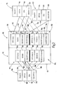
- the data memory 92 is shown in which various values are stored according to a first embodiment.
- the data memory 92 has a first memory subarea 110, which is provided for the storage of safety-relevant program variables.
- the data memory 92 has a second memory subarea 112, which is provided for the storage of non-safety-related program variables.
- This structure of the data memory 92 is not intended to be restrictive. It is also conceivable to provide two structurally independent data memories, one of which is provided for the safety-relevant program variables and the other for the non-safety-relevant program variables.
- the safety controller 10 is two-channel redundant design.
- Reference numeral 114 designates a processing of a plurality of first safety-related program variables taking place in a first channel 88.
- One of the first safety-related program variables processed in the first channel 88 is the safety-relevant program variable FSV1A, which is designated by the reference number 116.
- the nomenclature used has the following meaning: FS stands for "failsafe" and thus indicates that this is a safety-relevant program variable.
- V1 is the actual name of the considered safety-relevant program variables, on the basis of which these are in the multiplicity of the first safety-relevant program variables, that of the first safety-relevant program variables Processor 20 can be identified.
- the letter A indicates that it is a program variable processed in the first channel 88. This nomenclature will be for the Fig. 2 and 3 used uniformly.
- Reference numeral 118 denotes a write counter SZA used in the first channel 88.
- the value of the write counter SZA indicates the number of write operations with which instantaneous values of the safety-relevant program variables FSV1A are written into the first memory subarea 110.
- Reference numeral 120 denotes a check value determination CRCFSV1A performed in the first channel 88 for the safety-related program variable FSV1A.
- the letters CRC cyclic redundancy check
- Reference numeral 122 denotes a processing of a plurality of second safety-related program variables taking place in a second channel 90.
- One of the second security-related program variables processed in the second channel 90 is the security-relevant program variable FSV1B designated by the reference numeral 124.
- the letter B indicates that it is a program variable processed in the second channel 90.
- Reference numeral 126 denotes a write counter SZB used in the second channel 90.
- the value of the write counter SZB corresponds to the value of the write counter SZA.
- Reference numeral 128 denotes a check value determination CRCFSV1B performed in the second channel 90 for the safety-related program variable FSV1B.
- the safety-relevant program variable FSV1B corresponds with the safety-relevant program variable FSV1A.
- a first machine code 40 for the first channel 88 and a second machine code 42 for the second channel 90 are stored for fail-safe operation of the safety controller 10 in the program memory 32, wherein both machine codes 40, 42 each comprise a separate security code 44, 48.
- each of the two security codes contains 44, 48 own program variables, the first security code 44 first security-related program variables and the second security code 48 second security-related program variables.
- both the first security code 44 and the second security code 48 each contain a security-relevant program input variable with which the instantaneous values of the sensor signal generated by the same emergency-off button can be read.
- safety-relevant program output variables and possibly required safety-relevant program intermediate variables are independent of one another in the sense that the first program variables and the second program variables occupy independent memory areas in the respective memories.
- the two security codes 44, 48 contain pairs of corresponding program variables.
- both the first security code 44 and the second security code 48 each contain a security-relevant program input variable with which the instantaneous values of the sensor signal generated by the same emergency-off button can be read. The same applies to safety-relevant program output variables and possibly required safety-relevant program intermediate variables.
- instantaneous values of the safety-relevant program variables FSV1A, values of the write counter SZA, and test values determined with the two test value determinations CRCFSV1A and CRCFSV1B are stored as follows:
- the first memory subarea has two memory areas 130, 132.
- An instantaneous value FSV1A (n) of the first program variable FSV1A present at a first defined instant is stored in the first memory area 130 in a first memory cell 134, which is represented by an arrow 136.
- the nomenclature used has the following meaning:
- the appended bracket expression (s) indicates that it is an instantaneous value. This instantaneous value is present at a first defined time, this time being within the task cycle n.
- the task cycle is the time duration that the safety controller 10 needs to cycle through the user program, starting with the updating of the input image, the processing of the individual control instructions and ending with the provision of the output image. Consequently, it suffices, for example, for a safety-relevant program input variable and a safety-related program output variable, to set the smallest time unit to the task cycle, since for these program variables only one change is made per task cycle.
- n denotes a first defined time and thus the task cycle in which this time is.
- the term (n-1) denotes an older time and thus one of the preceding task cycles.
- the term (n + 1) denotes a more recent time and thus one of the subsequent task cycles.
- the value SZA (n) of the write counter SZA present at the first defined instant is also stored in the first memory area 130, namely in a second memory cell 138, which is represented by an arrow 140. Furthermore, in the first memory area 130 a first check value CRCFSV1A (n), which is determined as a function of the instantaneous value FSV1A (n) from the check value determination CRCFSV1A and a second check value CRCFSV1B (n), namely in a third memory cell 142 and in a fourth memory cell 144, which is represented by arrows 146, 148.
- the second check value CRCFSV1B (n) determined with the second check value determination CRCFSV1B in this case corresponds to the first check value CRCFSV1A (n).
- the second check value CRCFSV1B (n) is determined as a function of an instantaneous value of that second program variable FSV1B which corresponds to the first program variable FSV1A.
- the instantaneous value of the second program variable FSV1B is present in the same task cycle as the instantaneous value FSV1A (n) of the first program variable FSV1A.
- the two check values CRCFSV1A (n) and CRCFSV1B (n) are determined diversified.
- the two check value determination CRCFSV1A and CRCFSV1B are implemented in terms of hardware technology and / or software technology.
- the individual values stored in the memory area 132 are determined in a corresponding manner, as described for the corresponding values stored in the memory area 130.
- the values stored in the memory cells 134, 138, 142, 150, 152, 154 are determined by the first processor 20.
- the values stored in the memory cells 144, 156 are determined by the second processor 22.
- Both the instantaneous value of the first program variable FSV1A and the two test values determined with the test value meanings CRCFSV1A and CRCFSV1B are stored alternately in the two memory areas 130, 132.
- the two test values are thus repeatedly determined and stored for successive times.
- the instantaneous value FSV1A (n + 1) present at this time and the two check values CRCFSV1A (n + 1) and CRCFSV1B (n + 1) are then stored in the corresponding memory cells 150, 152, 154, 156 of the memory area 132 stored.
- the data memory 92 has two memory areas 130, 132 which are assigned to the safety-relevant program variable FSV1A. If further security-relevant program variables are stored in the data memory 92 in accordance with the above-described procedure, then this also has two memory areas for each of these program variables.
- the first processor 20 may be configured to perform an instantaneous value comparison. With this instantaneous value comparison, the instantaneous values of the safety-related program variables FSV1A present at different times are compared with one another. If it is determined by the instantaneous value comparison that the two instantaneous values of two directly consecutive times do not differ, then it is possible to save the younger instantaneous values and the two younger test values are dispensed with. In other words, the younger instantaneous value and the two younger instantaneous values are only stored if the younger instantaneous value differs from the instantaneous value present for the immediately preceding instant.
- the first check value CRCFSV1A (n) is determined as a function of the instantaneous value FSV1A (n) by the check value determination CRCFSV1A.
- the second check value CRCFSV1B (n) is determined as a function of the instantaneous value FSV1B (n) by the check value determination CRCFSV1B.
- the first check value CRCFSV1A (n) can also be determined for the combination which results from the instantaneous value FSV1A (n) and the value SZA (n) of the write counter SZA. Accordingly, it is possible to proceed for the second check value CRCFSV1B (n).
- the above-described storage of instantaneous values, write counter values and test values in the first memory subregion is based on the following consideration. For example, as long as there is no power failure, the safety controller 10 thus operates without interference, the two safety-relevant program variables FSV1A and FSV1B have identical instantaneous values in the individual task cycles. Consequently, it is sufficient to store in the data memory 92 only the instantaneous values of the safety-related program variables FSV1A.
- the two write counters SZA and SZB also have identical values within a task cycle.
- the second processor 22 is also supplied with the instantaneous value FSV1A (n), but the second check value CRCFSV1B (n). If the safety controller 10 has worked without interruptions in the time window in which the two test values CRCFSV1A (n) and CRCFSV1B (n) have been determined and both the instantaneous value FSV1A (n) and these two test values have been stored in the data memory 92, a further determination of a first current check value CRCFSV1A (n + 1) and a current second check value CRCFSV1B (n + 1) that both the stored first check value CRCFSV1A (n) and the current first check value CRCFSV1A (n + 1) are identical and the stored second check value CRCFSV1B (n) and the current second check value CRCFSV1B (n + 1) are identical.
- the stored instantaneous value FSV1A (n) is valid and can be used for the initialization of the safety controller 10. It is processed in both channels 88, 90. On the other hand, it is determined that either the stored first check value CRCFSV1A (n) and the current first check value CRCFSV1A (n + 1) are not identical or the stored second check value CRCFSV1B (n) and the current second check value CRCFSV1B (n + 1) are not identical are stored, then the stored instantaneous value FSV1A (n) is not valid and thus can not be used for the initialization of the safety controller 10. In this case, the previously stored instantaneous value FSV1A (n-1) is used instead for the initialization.
- this instantaneous value, before it is used for the initialization, is first also subjected to a validity check.
- the safety controller 10 and the system 12 can be restarted without requiring the use of default values for the first safety-related program variable FSV1A or performing a homing run.
- the data memory 92 has a second memory subarea 112, which is provided for the storage of non-safety-related program variables, wherein the non-safety-related program variables are processed in the first channel 88.
- Reference numeral 166 denotes a processing of a plurality of non-safety-related program variables taking place in a first channel 88.
- One of the first non-safety-related program variables processed in the first channel 88 is the safety-relevant program variable STV1A designated by the reference numeral 168.
- ST stands for "standard” and thus indicates that it is a non-security-relevant program variable.
- V1 and the letter A can be found in the explanations concerning the processing designated by the reference numeral 114.
- Reference numeral 170 denotes a check value determination CRCSTV1A performed in the first channel 88 for the non-safety-related program variable STV1A.
- instantaneous values of the non-safety-related program variables STV1A, values of the write counter SZA, and test values determined with the test value determination CRCSTV1A are stored as follows:
- the second memory subarea 112 has two memory areas 172, 174.
- An instantaneous value STV1A (n) of the first non-safety-related program variable STV1A present at a first defined instant is stored in the third memory area 172 in a ninth memory cell 176, which is illustrated by an arrow 178.
- the value SZA (n) of the write counter SZA present at the first defined instant is likewise stored in a tenth memory cell 180, which is represented by an arrow 182.
- test value CRCSTV1A (n) is stored, which is determined as a function of the instantaneous value STV1A (n) from the test value determination CRCSTV1A, namely in an eleventh memory cell 184, which is illustrated by an arrow 186.
- an instantaneous value STV1A (n-1) of the non-safety-relevant one is for an older point in time and thus a preceding task cycle
- Program variables STV1A, a value SZA (n-1) of the write counter SZA and a check value CRCSTV1A (n-1) of a twelfth memory cell 188, a thirteenth memory cell 190 and a fourteenth memory cell 192 are stored, which is represented by arrows 194, 196, 198.
- the individual values stored in the fourth memory area 1174 are determined in a corresponding manner, as described for the corresponding values stored in the third memory area 172.
- the values stored in the memory cells 176, 180, 184, 188, 190, 192 are determined by the first processor 20.
- Both the instantaneous value of the non-safety-related program variable STV1A and the test value determined using the test value determination means CRCSTV1A are stored alternately in the two memory areas 172, 174.
- the instantaneous value STV1A (n + 1) present at this time and the check value CRCSTV1A (n + 1) are then stored in the corresponding memory cells 188, 190, 192 of the fourth memory area 174.
- the data memory 92 has two memory areas 172, 174 which are assigned to the non-safety-related program variable STV1A. If further non-safety-related program variables are stored in the data memory 92 in accordance with the above-described procedure, then this also has two memory areas for each of these program variables.
- non-safety-relevant program variables can also take place taking into account an instantaneous value comparison.
- the value of the write counter SZA can be taken into account when determining test values.
- the validation of a last stored instantaneous value STV1A (n) takes place in the same way as described above for the safety-related program variables.
- the instantaneous value STV1A (n) and the test value CRCSTV1A (n) are supplied to the first processor 20. If the safety controller 10 has worked without interruption in the time window in which the test value CRCSTV1A (n) has been determined and both the instantaneous value STV1A (n) and the test value CRCSTV1A (n) have been stored in the data memory 92, then a renewed test value CRCSTV1A is determined (n + 1) that the stored check value CRCSTV1A (n) and the current check value CRCSTV1A (n + 1) are identical.
- the stored instantaneous value STV1A (n) is valid and can be used for the initialization of the safety controller 10. It is processed in the first channel 88.
- the stored check value CRCSTV1A (n) and the current check value CRCSTV1A (n + 1) are not identical, then the stored present value STV1A (n) is not valid and thus can not be used for the initialization of the safety controller 10.
- the previously stored instantaneous value STV1A (n-1) is used instead for the initialization.
- this instantaneous value, before it is used for the initialization is first also subjected to a validity check.
- the safety controller 10 and the system 12 can be restarted without requiring the use of default values for the non-safety-related program variable STV1A or carrying out a homing run.
- the program variables processed by the first processor 20 are collectively referred to as first program variables and the program variables processed by the second processor 22 are collectively referred to as second program variables.
- Fig. 3 the data memory 92 is shown in which various values are stored according to a second embodiment.
- the reference numeral 114 denotes a processing in the first channel 88 of a plurality of first safety-related program variables, which differs from the processing 114 in that no write counter SZA is taken into account.
- reference numeral 122 'de notes processing of second safety-related program variables occurring in the second channel 90
- reference numeral 166' denotes processing of non-safety-related program variables occurring in the first channel 88.
- a current value FSV1A (n) of the first program variable FSV1A, a first check value CRCFSV1A (n) and a second check value CRCFSV1B (n) are stored in a fifteenth memory cell 202, a sixteenth memory cell 204 and a seventeenth memory cell 206, respectively represented by arrows 208, 210, 212.
- an instantaneous value STV1A (n) of a non-safety-related program variable STV1A and a test value CRCSTV1A (n) are stored in an eighteenth memory cell 216 and a nineteenth memory cell 218, which is illustrated by arrows 220, 222.
- the values stored in the memory cells 202, 204, 216, 218 are determined by the first processor 20.
- the value stored in memory cell 206 is determined by second processor 22.
- the individual stored values are added according to the explanations Fig. 2 determined.
- the validity check of the stored instantaneous values FSV1A (n) and STV1A (n) takes place in the same way as in connection with Fig. 2 is described. However, with the following difference: if it is determined that, for example, the instantaneous value FSV1A (n) is not valid, no further instantaneous value is stored in the data memory 92 for the first safety-related program variable FSV1A, which could be used instead of the instantaneous value FSV1A (n). In this case, the safety controller 10 must either be initialized with a default value for the first safety-related program variable FSV1A or a reference run with the system 12 must be carried out. The same applies to the non-safety-related program variable STV1A.
Landscapes
- Physics & Mathematics (AREA)
- General Physics & Mathematics (AREA)
- Engineering & Computer Science (AREA)
- Automation & Control Theory (AREA)
- Safety Devices In Control Systems (AREA)
- Programmable Controllers (AREA)
Claims (13)
- Commande sécurisée destinée à commander une installation automatique (12) en application d'un programme d'utilisateur (34) qui est exécuté dans la commande sécurisée,
l'installation (12) comportant plusieurs capteurs (16) et plusieurs actionneurs (14),
le programme d'utilisateur (34) composant plusieurs ordres de commande (44, 46, 48) qui commandent les actionneurs (14),
la commande sécurisée présentant un premier processeur (20) configuré pour exécuter au moins une partie des ordres de commande (44) par traitement de plusieurs premières variables du programme,
un deuxième processeur (22) configuré pour exécuter au moins une partie des ordres de commande (48) par traitement de plusieurs deuxièmes variables du programme,
une mémoire non volatile (92) de données protégée contre les tensions nulles et qui doivent être présentes en cas de chute de tension lorsque la commande sécurisée est branchée,
le premier et le deuxième processeur (20, 22) étant tous deux configurés pour déterminer des valeurs de vérification qui permettent de vérifier la validité d'une valeur conservée dans la mémoire (92) de données,
caractérisée en ce que
le premier processeur (20) est configuré pour déterminer pour au moins une des premières variables (FSV1A) du programme une première valeur de vérification (CRCFSV1A(n)) en fonction d'une valeur instantanée (FSV1A(n)) qui prévaut à un premier instant défini pour cette variable (FSV1A) du programme,
en ce que le deuxième processeur (22) est en outre configuré pour déterminer une deuxième valeur de vérification (CRCFSV1B(n)) qui correspond à la première valeur de vérification (CRCFSV1A(n)),
en ce que la mémoire (92) de données est configurée pour conserver la valeur instantanée (FSV1A(n)), la première valeur de vérification (CRCFSV1A(n)) et la deuxième valeur de vérification (CRCFSV1B(n)),
en ce que la commande sécurisée (10) est configurée pour, lors de son redémarrage, exécuter une vérification de la validité de la valeur instantanée (FSV1A(n)) et
en ce que la commande sécurisée (10) est en outre configurée pour plausibiliser au moyen du premier processeur (20) la valeur instantanée (FSV1A(n)) par rapport à sa première valeur de vérification (CRCFSV1A(n)) et pour plausibiliser au moyen du deuxième processeur (22) la valeur instantanée (FSV1A(n)) par rapport à la deuxième valeur de vérification (CRCFSV1B(n)). - Commande sécurisée selon la revendication 1, caractérisée en ce que le deuxième processeur (22) est en outre configuré pour déterminer la deuxième valeur de vérification (CRCFSV1B(n)) en fonction d'une valeur instantanée (FSV1B(n)) de l'une des deuxièmes variables (FSV1B) du programme, la deuxième variable (FSV1B) du programme correspondant à la première variable (FSV1A) du programme.
- Commande sécurisée selon la revendication 2, caractérisée en ce que la valeur instantanée (FSV1A(n)) des premières variables (FSV1A) du programme et la valeur instantanée (FSV1B(n)) des deuxièmes variables (FSV1B) du programme sont présentes dans le même cycle (n) d'exécution.
- Commande sécurisée selon l'une des revendications précédentes, caractérisée en ce que la commande sécurisée (10) est configurée pour déterminer de manière différente les deux valeurs de vérification (CRCFSV1A(n), CRCFSV1B(n)).
- Commande sécurisée selon l'une des revendications précédentes, caractérisée en ce que la commande sécurisée (10) est configurée pour déterminer de manière répétée à des instants successifs les deux valeurs de vérification (CRCFSV1A(n), CRCFSV1B(n)).
- Commande sécurisée selon l'une des revendications précédentes, caractérisée en ce que le premier processeur (20) est en outre configuré pour exécuter une comparaison des valeurs instantanées.
- Commande sécurisée selon l'une des revendications précédentes, caractérisée en ce que la mémoire (92) de données présente deux zones de mémoire (130, 132) associées aux premières variables (116) du programme.
- Commande sécurisée selon la revendication 7, caractérisée en ce que la commande sécurisée (10) est configurée pour conserver la valeur instantanée (FSV1A(n)) et les deux valeurs de vérification (CRCFSV1A(n)), CRCFSV1B(n)) en alternance dans les deux zones de mémoire (130, 132).
- Commande sécurisée selon la revendication 8, caractérisée en ce qu'au moins l'un des deux processeurs (20, 22) est configuré pour déterminer une valeur (SZA(n), SZB(n)) d'un compteur d'écriture (SZA, SZB), le compteur d'écriture (SZA, SZB) représentant celle de la zone de mémoire (130, 132) qui contient la valeur instantanée la plus récente.
- Commande sécurisée selon la revendication 9, caractérisée en ce que le premier processeur (20) est en outre configuré pour déterminer la première valeur de vérification (CRCFSV1A(n)) en fonction de la valeur instantanée (FSV1A(n)) et de la valeur (SZA(n)) du compteur d'écriture (SZA).
- Commande sécurisée selon l'une des revendications précédentes, caractérisée en ce que les premières et les deuxièmes valeurs du programme sont des variables du programme qui concernent la sécurité.
- Procédé de commande d'une installation automatique (12) à l'aide d'une commande sécurisée qui présente un premier processeur (20) et un deuxième processeur (22), l'installation (12) comportant plusieurs capteurs (16) et plusieurs actionneurs (14), le procédé présentant les étapes qui consistent à :traiter plusieurs des premières variables du programme à l'aide du premier processeur (20),déterminer une première valeur de vérification (CRCFSV1A(n)) pour au moins l'une des premières variables (FSV1A) du programme en fonction d'une valeur instantanée (FSV1A(n)) qui prévaut pour cette première variable (FSV1A) du programme à un premier instant défini, à l'aide du premier processeur (20),traiter plusieurs des deuxièmes variables du programme à l'aide du deuxième processeur (22),déterminer une deuxième valeur de vérification (CRCFSV1B(n)) qui correspond à la première valeur de vérification (CRCFSV1A(n)), à l'aide du deuxième processeur (22),conserver en mémoire la valeur instantanée (FSV1A(n)) de la première valeur de vérification (CRCFSV1A(n)) et la deuxième valeur de vérification (CRCFSV1B(n)) dans une mémoire non volatile (92) de données etexécuter une vérification de la validité de la valeur instantanée (FSV1A(n)) lors du redémarrage de la commande sécurisée, la commande sécurisée (10) plausibilisant au moyen du premier processeur (20) la valeur instantanée (FSV1A(n)) par rapport à la première valeur de vérification (CRCFSV1A(n)) et plausibilisant au moyen du deuxième processeur (22) la valeur instantanée (FSV1A(n)) par rapport à la deuxième valeur de vérification (CRCFSV1B(n)).
- Produit de programme informatique doté d'un support de données qui présente des codes de programme et configuré pour exécuter un procédé selon la revendication 12 lorsque le code de programme se déroule sur une commande sécurisée (10) selon l'une des revendications 1 à 11.
Applications Claiming Priority (2)
| Application Number | Priority Date | Filing Date | Title |
|---|---|---|---|
| DE200910019087 DE102009019087A1 (de) | 2009-04-20 | 2009-04-20 | Sicherheitssteuerung und Verfahren zum Steuern einer automatisierten Anlage |
| PCT/EP2010/002436 WO2010121796A1 (fr) | 2009-04-20 | 2010-04-20 | Commande de sécurité et procédé de commande d'une installation automatisée |
Publications (2)
| Publication Number | Publication Date |
|---|---|
| EP2422244A1 EP2422244A1 (fr) | 2012-02-29 |
| EP2422244B1 true EP2422244B1 (fr) | 2013-11-27 |
Family
ID=42334649
Family Applications (1)
| Application Number | Title | Priority Date | Filing Date |
|---|---|---|---|
| EP20100718871 Active EP2422244B1 (fr) | 2009-04-20 | 2010-04-20 | Commande de sécurité et procédé de commande d'une installation automatisée |
Country Status (8)
| Country | Link |
|---|---|
| US (1) | US9098074B2 (fr) |
| EP (1) | EP2422244B1 (fr) |
| JP (2) | JP5645921B2 (fr) |
| CN (1) | CN102460316B (fr) |
| DE (1) | DE102009019087A1 (fr) |
| ES (1) | ES2446349T3 (fr) |
| HK (1) | HK1166523A1 (fr) |
| WO (1) | WO2010121796A1 (fr) |
Families Citing this family (11)
| Publication number | Priority date | Publication date | Assignee | Title |
|---|---|---|---|---|
| DE102008060005A1 (de) * | 2008-11-25 | 2010-06-10 | Pilz Gmbh & Co. Kg | Sicherheitssteuerung und Verfahren zum Steuern einer automatisierten Anlage mit einer Vielzahl von Anlagenhardwarekomponenten |
| JP5683294B2 (ja) * | 2011-01-31 | 2015-03-11 | 三菱重工業株式会社 | 安全装置、安全装置の演算方法 |
| DE102011088236A1 (de) * | 2011-12-12 | 2013-06-13 | Endress + Hauser Wetzer Gmbh + Co. Kg | Verfahren zum sicheren Betreiben eines Feldgerätes der Prozessautomatisierungstechnik |
| US9696692B2 (en) * | 2012-04-13 | 2017-07-04 | Rockwell Automation Technologies, Inc. | Industrial automation control system |
| DE102012012521A1 (de) | 2012-06-26 | 2014-01-02 | Inter Control Hermann Köhler Elektrik GmbH & Co. KG | Vorrichtung und Verfahren für eine sicherheitskritische Anwendung |
| JP5545380B1 (ja) * | 2013-01-28 | 2014-07-09 | 株式会社安川電機 | ロボットシステム |
| US10185291B2 (en) * | 2013-06-28 | 2019-01-22 | Fisher Controls International Llc | System and method for shutting down a field device |
| DE102016202749A1 (de) * | 2016-02-23 | 2017-08-24 | Festo Ag & Co. Kg | Sicherheitsgerichtete Steuervorrichtung und Verfahren zum Betrieb einer sicherheitsgerichteten Steuervorrichtung |
| DE102016125240A1 (de) * | 2016-12-21 | 2018-06-21 | Endress+Hauser SE+Co. KG | Elektronische Schaltung für ein Feldgerät der Automatisierungstechnik |
| US11879871B2 (en) * | 2018-11-30 | 2024-01-23 | Illinois Tool Works Inc. | Safety systems requiring intentional function activation and material testing systems including safety systems requiring intentional function activation |
| CN113127262B (zh) * | 2020-01-13 | 2024-05-14 | 北京地平线机器人技术研发有限公司 | 镜像文件的生成方法、装置、电子设备及存储介质 |
Family Cites Families (42)
| Publication number | Priority date | Publication date | Assignee | Title |
|---|---|---|---|---|
| US3751684A (en) * | 1972-04-14 | 1973-08-07 | Allen Bradley Co | Fault mode detection system |
| US4193120A (en) * | 1978-09-13 | 1980-03-11 | Zenith Radio Corporation | Addressable event display and control system |
| US4787041A (en) * | 1985-08-01 | 1988-11-22 | Honeywell | Data control system for digital automatic flight control system channel with plural dissimilar data processing |
| JPH02114827A (ja) * | 1988-10-21 | 1990-04-26 | Tokyo Electric Co Ltd | バックアップ電源装置 |
| JPH0527880A (ja) * | 1991-07-23 | 1993-02-05 | Nippon Steel Corp | システムリスタート装置 |
| US5414836A (en) * | 1993-09-29 | 1995-05-09 | International Business Machines Corporation | Software testing system that employs a graphical interface to generate test cases configured as hybrid tree structures |
| JPH07295602A (ja) * | 1994-04-22 | 1995-11-10 | Shimadzu Corp | 二重化制御装置 |
| JP3210833B2 (ja) * | 1995-05-09 | 2001-09-25 | 株式会社日立製作所 | エラーチェック方法および装置 |
| JP3208060B2 (ja) * | 1996-05-27 | 2001-09-10 | 三菱電機株式会社 | 並列二重系電子連動装置 |
| DE19636703C2 (de) * | 1996-09-10 | 1998-12-03 | Roland Man Druckmasch | Vorrichtung zur automatischen Steuerung eines Druckplattenwechselvorganges |
| DE19802728A1 (de) * | 1998-01-24 | 1999-07-29 | Heidenhain Gmbh Dr Johannes | Verfahren und Schaltungsanordnung zur Überwachung von Maschinenparametern |
| US6647301B1 (en) * | 1999-04-22 | 2003-11-11 | Dow Global Technologies Inc. | Process control system with integrated safety control system |
| DE19927635B4 (de) * | 1999-06-17 | 2009-10-15 | Phoenix Contact Gmbh & Co. Kg | Sicherheitsbezogenes Automatisierungsbussystem |
| US6556950B1 (en) * | 1999-09-30 | 2003-04-29 | Rockwell Automation Technologies, Inc. | Diagnostic method and apparatus for use with enterprise control |
| US6777830B1 (en) * | 2000-03-17 | 2004-08-17 | Pilz Gmbh & Company | System for reliable prevention of the restarting of a machine |
| FR2806934B1 (fr) * | 2000-03-30 | 2003-04-18 | Eisenmann France Sarl | Dispositif de controle d'une installation de traitement de surface, notamment pour l'industrie automobile |
| US6745107B1 (en) * | 2000-06-30 | 2004-06-01 | Honeywell Inc. | System and method for non-invasive diagnostic testing of control valves |
| WO2002008867A2 (fr) * | 2000-07-25 | 2002-01-31 | Dutec, Inc. | Système, dispositif et procédé d'interface d'entrées/sorties globale entre process ou transducteurs de la machine et le dispositif ou système de régulation |
| US6643555B1 (en) * | 2000-10-10 | 2003-11-04 | Schneider Automation Inc. | Method and apparatus for generating an application for an automation control system |
| US6549827B1 (en) * | 2000-11-20 | 2003-04-15 | John Yen | Fire prevention automation commanding control system using satellite-location/geography-information |
| US20050188351A1 (en) * | 2002-04-02 | 2005-08-25 | Siemens Aktiengesellschaft | Device and method for automatically generating automation software |
| FR2841007B1 (fr) * | 2002-06-18 | 2004-07-23 | Schneider Automation | Systeme de communication de securite |
| US7610119B2 (en) * | 2003-07-08 | 2009-10-27 | Omron Corporation | Safety controller and system using same |
| US7133727B2 (en) * | 2003-08-01 | 2006-11-07 | Invensys Systems, Inc. | System and method for continuous online safety and reliability monitoring |
| US7213168B2 (en) * | 2003-09-16 | 2007-05-01 | Rockwell Automation Technologies, Inc. | Safety controller providing for execution of standard and safety control programs |
| US7187989B2 (en) * | 2003-12-22 | 2007-03-06 | Fakhruddin T Attarwala | Use of core process models in model predictive controller |
| DE102004018857A1 (de) * | 2004-04-19 | 2005-11-10 | Elektro Beckhoff Gmbh Unternehmensbereich Industrie Elektronik | Sicherheitssteuerung |
| US7453677B2 (en) * | 2004-10-06 | 2008-11-18 | Teknic, Inc. | Power and safety control hub |
| DE102004058472B4 (de) * | 2004-11-24 | 2006-12-14 | Pilz Gmbh & Co. Kg | Sicherheitseinrichtung und Verfahren zum Bestimmen eines Nachlaufweges bei einer Maschine |
| US8055814B2 (en) * | 2005-03-18 | 2011-11-08 | Rockwell Automation Technologies, Inc. | Universal safety I/O module |
| US7599752B2 (en) * | 2005-05-17 | 2009-10-06 | Utah State University | Tuning methods for fractional-order controllers |
| US20070019641A1 (en) * | 2005-07-22 | 2007-01-25 | Rockwell Automation Technologies, Inc. | Execution of industrial automation applications on communication infrastructure devices |
| US20070035255A1 (en) * | 2005-08-09 | 2007-02-15 | James Shuster | LED strobe for hazard protection systems |
| US7933676B2 (en) * | 2005-09-30 | 2011-04-26 | Rockwell Automation Technologies, Inc. | Automation system with integrated safe and standard control functionality |
| US20070271002A1 (en) * | 2006-05-22 | 2007-11-22 | Hoskinson Reed L | Systems and methods for the autonomous control, automated guidance, and global coordination of moving process machinery |
| DE202006016012U1 (de) * | 2006-10-19 | 2006-12-21 | Sick Ag | Systemarchitektur für eine Firmware |
| US7617412B2 (en) * | 2006-10-25 | 2009-11-10 | Rockwell Automation Technologies, Inc. | Safety timer crosscheck diagnostic in a dual-CPU safety system |
| US20080208374A1 (en) * | 2007-02-27 | 2008-08-28 | Rockwell Automation Technologies, Inc. | Testing utilizing controller engine instances |
| US8409441B2 (en) * | 2007-02-27 | 2013-04-02 | Deka Products Limited Partnership | Blood treatment systems and methods |
| DE102007045398A1 (de) * | 2007-09-21 | 2009-04-02 | Continental Teves Ag & Co. Ohg | Integriertes Mikroprozessorsystem für sicherheitskritische Regelungen |
| US8165863B2 (en) * | 2008-09-11 | 2012-04-24 | Siemens Corporation | Visualization method for electrical machine operation models based on mechanical machine operation models |
| US8949480B2 (en) * | 2009-05-11 | 2015-02-03 | GM Global Technology Operations LLC | Method and system for testing safety automation logic of a manufacturing cell |
-
2009
- 2009-04-20 DE DE200910019087 patent/DE102009019087A1/de active Pending
-
2010
- 2010-04-20 WO PCT/EP2010/002436 patent/WO2010121796A1/fr active Application Filing
- 2010-04-20 ES ES10718871T patent/ES2446349T3/es active Active
- 2010-04-20 CN CN201080027532.4A patent/CN102460316B/zh active Active
- 2010-04-20 EP EP20100718871 patent/EP2422244B1/fr active Active
- 2010-04-20 JP JP2012506392A patent/JP5645921B2/ja active Active
-
2011
- 2011-10-19 US US13/276,909 patent/US9098074B2/en active Active
-
2012
- 2012-07-23 HK HK12107169A patent/HK1166523A1/xx not_active IP Right Cessation
-
2014
- 2014-07-11 JP JP2014143409A patent/JP5911922B2/ja active Active
Also Published As
| Publication number | Publication date |
|---|---|
| CN102460316B (zh) | 2014-06-18 |
| JP2012524353A (ja) | 2012-10-11 |
| JP2014225276A (ja) | 2014-12-04 |
| JP5645921B2 (ja) | 2014-12-24 |
| WO2010121796A1 (fr) | 2010-10-28 |
| CN102460316A (zh) | 2012-05-16 |
| DE102009019087A1 (de) | 2010-11-11 |
| HK1166523A1 (en) | 2012-11-02 |
| JP5911922B2 (ja) | 2016-04-27 |
| EP2422244A1 (fr) | 2012-02-29 |
| US9098074B2 (en) | 2015-08-04 |
| ES2446349T3 (es) | 2014-03-07 |
| US20120095573A1 (en) | 2012-04-19 |
Similar Documents
| Publication | Publication Date | Title |
|---|---|---|
| EP2422244B1 (fr) | Commande de sécurité et procédé de commande d'une installation automatisée | |
| EP2422271B1 (fr) | Procédé et dispositif d'établissement d'un programme utilisateur pour une commande de sécurité | |
| EP2399174B1 (fr) | Procédé et dispositif pour réaliser un programme d'application pour une commande de sécurité | |
| EP2353052B1 (fr) | Commande de sécurité et procédé de commande d une installation automatisée | |
| EP1362269B1 (fr) | Procede et dispositif de programmation d'une commande de securite | |
| EP2356526B1 (fr) | Commande de sécurité et procédé de commande d'une installation automatisée | |
| EP2422243B1 (fr) | Commande de sécurité pour commander une installation automatisée et procédé de génération d'un programme d'application pour une commande de sécurité | |
| EP3173884B1 (fr) | Procédé de programmation d'une commande de sécurité | |
| EP1887444B1 (fr) | Commande de processus | |
| EP0742499A2 (fr) | Traitement fiable de signaux orientés sûreté | |
| EP2356527B1 (fr) | Commande de sécurité et procédé pour commander une installation automatisée comprenant une pluralité de composants matériels | |
| EP3098673B1 (fr) | Procede et dispositif de validation automatique de fonctions de securite sur un systeme de securite construit de façon modulaire | |
| WO2000067080A1 (fr) | Regulateur ou regulateur de propulseur, propulseur et procede pour reguler un systeme de reglage ou d'entrainement ou un propulseur | |
| EP3082002A1 (fr) | Commande de securite et procede de commande d'une installation automatisee | |
| EP3470937B1 (fr) | Procédé et dispositifs de surveillance du temps réactionnel d'une fonction de sécurité fournie par un système de sécurité | |
| DE3919558C2 (fr) | ||
| EP3726313B1 (fr) | Commutateur de sécurité | |
| DE102007062915A1 (de) | Verfahren zum Betreiben einer speicherprogrammierbaren Steuerung | |
| EP3647889A1 (fr) | Contrôle de séquence de processus protégé contre les erreurs | |
| EP2482154A1 (fr) | Procédé et appareil de commande destinés à commander un composant d'automatisation industriel orienté vers la protection | |
| DE202019102189U1 (de) | Sicherheitsschaltvorrichtung | |
| EP2015154A1 (fr) | Procédé destiné à l'opération d'un appareil d'automatisation comprenant des modes d'arrêt configurables |
Legal Events
| Date | Code | Title | Description |
|---|---|---|---|
| PUAI | Public reference made under article 153(3) epc to a published international application that has entered the european phase |
Free format text: ORIGINAL CODE: 0009012 |
|
| 17P | Request for examination filed |
Effective date: 20111116 |
|
| AK | Designated contracting states |
Kind code of ref document: A1 Designated state(s): AT BE BG CH CY CZ DE DK EE ES FI FR GB GR HR HU IE IS IT LI LT LU LV MC MK MT NL NO PL PT RO SE SI SK SM TR |
|
| DAX | Request for extension of the european patent (deleted) | ||
| REG | Reference to a national code |
Ref country code: HK Ref legal event code: DE Ref document number: 1166523 Country of ref document: HK |
|
| GRAP | Despatch of communication of intention to grant a patent |
Free format text: ORIGINAL CODE: EPIDOSNIGR1 |
|
| INTG | Intention to grant announced |
Effective date: 20130604 |
|
| GRAS | Grant fee paid |
Free format text: ORIGINAL CODE: EPIDOSNIGR3 |
|
| GRAA | (expected) grant |
Free format text: ORIGINAL CODE: 0009210 |
|
| AK | Designated contracting states |
Kind code of ref document: B1 Designated state(s): AT BE BG CH CY CZ DE DK EE ES FI FR GB GR HR HU IE IS IT LI LT LU LV MC MK MT NL NO PL PT RO SE SI SK SM TR |
|
| REG | Reference to a national code |
Ref country code: GB Ref legal event code: FG4D Free format text: NOT ENGLISH |
|
| REG | Reference to a national code |
Ref country code: CH Ref legal event code: EP |
|
| REG | Reference to a national code |
Ref country code: AT Ref legal event code: REF Ref document number: 642953 Country of ref document: AT Kind code of ref document: T Effective date: 20131215 |
|
| REG | Reference to a national code |
Ref country code: IE Ref legal event code: FG4D Free format text: LANGUAGE OF EP DOCUMENT: GERMAN |
|
| REG | Reference to a national code |
Ref country code: DE Ref legal event code: R096 Ref document number: 502010005497 Country of ref document: DE Effective date: 20140123 |
|
| REG | Reference to a national code |
Ref country code: CH Ref legal event code: NV Representative=s name: RENTSCH PARTNER AG, CH |
|
| REG | Reference to a national code |
Ref country code: ES Ref legal event code: FG2A Ref document number: 2446349 Country of ref document: ES Kind code of ref document: T3 Effective date: 20140307 |
|
| REG | Reference to a national code |
Ref country code: SE Ref legal event code: TRGR |
|
| REG | Reference to a national code |
Ref country code: NL Ref legal event code: VDEP Effective date: 20131127 |
|
| REG | Reference to a national code |
Ref country code: LT Ref legal event code: MG4D |
|
| PG25 | Lapsed in a contracting state [announced via postgrant information from national office to epo] |
Ref country code: NL Free format text: LAPSE BECAUSE OF FAILURE TO SUBMIT A TRANSLATION OF THE DESCRIPTION OR TO PAY THE FEE WITHIN THE PRESCRIBED TIME-LIMIT Effective date: 20131127 Ref country code: FI Free format text: LAPSE BECAUSE OF FAILURE TO SUBMIT A TRANSLATION OF THE DESCRIPTION OR TO PAY THE FEE WITHIN THE PRESCRIBED TIME-LIMIT Effective date: 20131127 Ref country code: IS Free format text: LAPSE BECAUSE OF FAILURE TO SUBMIT A TRANSLATION OF THE DESCRIPTION OR TO PAY THE FEE WITHIN THE PRESCRIBED TIME-LIMIT Effective date: 20140327 Ref country code: NO Free format text: LAPSE BECAUSE OF FAILURE TO SUBMIT A TRANSLATION OF THE DESCRIPTION OR TO PAY THE FEE WITHIN THE PRESCRIBED TIME-LIMIT Effective date: 20140227 Ref country code: HR Free format text: LAPSE BECAUSE OF FAILURE TO SUBMIT A TRANSLATION OF THE DESCRIPTION OR TO PAY THE FEE WITHIN THE PRESCRIBED TIME-LIMIT Effective date: 20131127 Ref country code: LT Free format text: LAPSE BECAUSE OF FAILURE TO SUBMIT A TRANSLATION OF THE DESCRIPTION OR TO PAY THE FEE WITHIN THE PRESCRIBED TIME-LIMIT Effective date: 20131127 |
|
| PG25 | Lapsed in a contracting state [announced via postgrant information from national office to epo] |
Ref country code: CY Free format text: LAPSE BECAUSE OF FAILURE TO SUBMIT A TRANSLATION OF THE DESCRIPTION OR TO PAY THE FEE WITHIN THE PRESCRIBED TIME-LIMIT Effective date: 20131127 Ref country code: LV Free format text: LAPSE BECAUSE OF FAILURE TO SUBMIT A TRANSLATION OF THE DESCRIPTION OR TO PAY THE FEE WITHIN THE PRESCRIBED TIME-LIMIT Effective date: 20131127 |
|
| REG | Reference to a national code |
Ref country code: HK Ref legal event code: GR Ref document number: 1166523 Country of ref document: HK |
|
| PG25 | Lapsed in a contracting state [announced via postgrant information from national office to epo] |
Ref country code: PT Free format text: LAPSE BECAUSE OF FAILURE TO SUBMIT A TRANSLATION OF THE DESCRIPTION OR TO PAY THE FEE WITHIN THE PRESCRIBED TIME-LIMIT Effective date: 20140327 |
|
| PG25 | Lapsed in a contracting state [announced via postgrant information from national office to epo] |
Ref country code: EE Free format text: LAPSE BECAUSE OF FAILURE TO SUBMIT A TRANSLATION OF THE DESCRIPTION OR TO PAY THE FEE WITHIN THE PRESCRIBED TIME-LIMIT Effective date: 20131127 |
|
| REG | Reference to a national code |
Ref country code: DE Ref legal event code: R097 Ref document number: 502010005497 Country of ref document: DE |
|
| PG25 | Lapsed in a contracting state [announced via postgrant information from national office to epo] |
Ref country code: RO Free format text: LAPSE BECAUSE OF FAILURE TO SUBMIT A TRANSLATION OF THE DESCRIPTION OR TO PAY THE FEE WITHIN THE PRESCRIBED TIME-LIMIT Effective date: 20131127 Ref country code: PL Free format text: LAPSE BECAUSE OF FAILURE TO SUBMIT A TRANSLATION OF THE DESCRIPTION OR TO PAY THE FEE WITHIN THE PRESCRIBED TIME-LIMIT Effective date: 20131127 Ref country code: SK Free format text: LAPSE BECAUSE OF FAILURE TO SUBMIT A TRANSLATION OF THE DESCRIPTION OR TO PAY THE FEE WITHIN THE PRESCRIBED TIME-LIMIT Effective date: 20131127 Ref country code: CZ Free format text: LAPSE BECAUSE OF FAILURE TO SUBMIT A TRANSLATION OF THE DESCRIPTION OR TO PAY THE FEE WITHIN THE PRESCRIBED TIME-LIMIT Effective date: 20131127 |
|
| PG25 | Lapsed in a contracting state [announced via postgrant information from national office to epo] |
Ref country code: DK Free format text: LAPSE BECAUSE OF FAILURE TO SUBMIT A TRANSLATION OF THE DESCRIPTION OR TO PAY THE FEE WITHIN THE PRESCRIBED TIME-LIMIT Effective date: 20131127 |
|
| PLBE | No opposition filed within time limit |
Free format text: ORIGINAL CODE: 0009261 |
|
| STAA | Information on the status of an ep patent application or granted ep patent |
Free format text: STATUS: NO OPPOSITION FILED WITHIN TIME LIMIT |
|
| 26N | No opposition filed |
Effective date: 20140828 |
|
| PG25 | Lapsed in a contracting state [announced via postgrant information from national office to epo] |
Ref country code: MC Free format text: LAPSE BECAUSE OF FAILURE TO SUBMIT A TRANSLATION OF THE DESCRIPTION OR TO PAY THE FEE WITHIN THE PRESCRIBED TIME-LIMIT Effective date: 20131127 Ref country code: LU Free format text: LAPSE BECAUSE OF FAILURE TO SUBMIT A TRANSLATION OF THE DESCRIPTION OR TO PAY THE FEE WITHIN THE PRESCRIBED TIME-LIMIT Effective date: 20140420 |
|
| REG | Reference to a national code |
Ref country code: DE Ref legal event code: R097 Ref document number: 502010005497 Country of ref document: DE Effective date: 20140828 |
|
| REG | Reference to a national code |
Ref country code: IE Ref legal event code: MM4A |
|
| PG25 | Lapsed in a contracting state [announced via postgrant information from national office to epo] |
Ref country code: SI Free format text: LAPSE BECAUSE OF FAILURE TO SUBMIT A TRANSLATION OF THE DESCRIPTION OR TO PAY THE FEE WITHIN THE PRESCRIBED TIME-LIMIT Effective date: 20131127 |
|
| PG25 | Lapsed in a contracting state [announced via postgrant information from national office to epo] |
Ref country code: IE Free format text: LAPSE BECAUSE OF NON-PAYMENT OF DUE FEES Effective date: 20140420 |
|
| PG25 | Lapsed in a contracting state [announced via postgrant information from national office to epo] |
Ref country code: MT Free format text: LAPSE BECAUSE OF FAILURE TO SUBMIT A TRANSLATION OF THE DESCRIPTION OR TO PAY THE FEE WITHIN THE PRESCRIBED TIME-LIMIT Effective date: 20131127 |
|
| REG | Reference to a national code |
Ref country code: FR Ref legal event code: PLFP Year of fee payment: 7 |
|
| PG25 | Lapsed in a contracting state [announced via postgrant information from national office to epo] |
Ref country code: SM Free format text: LAPSE BECAUSE OF FAILURE TO SUBMIT A TRANSLATION OF THE DESCRIPTION OR TO PAY THE FEE WITHIN THE PRESCRIBED TIME-LIMIT Effective date: 20131127 |
|
| REG | Reference to a national code |
Ref country code: AT Ref legal event code: MM01 Ref document number: 642953 Country of ref document: AT Kind code of ref document: T Effective date: 20150420 |
|
| PG25 | Lapsed in a contracting state [announced via postgrant information from national office to epo] |
Ref country code: BG Free format text: LAPSE BECAUSE OF FAILURE TO SUBMIT A TRANSLATION OF THE DESCRIPTION OR TO PAY THE FEE WITHIN THE PRESCRIBED TIME-LIMIT Effective date: 20131127 Ref country code: GR Free format text: LAPSE BECAUSE OF FAILURE TO SUBMIT A TRANSLATION OF THE DESCRIPTION OR TO PAY THE FEE WITHIN THE PRESCRIBED TIME-LIMIT Effective date: 20140228 |
|
| PG25 | Lapsed in a contracting state [announced via postgrant information from national office to epo] |
Ref country code: TR Free format text: LAPSE BECAUSE OF FAILURE TO SUBMIT A TRANSLATION OF THE DESCRIPTION OR TO PAY THE FEE WITHIN THE PRESCRIBED TIME-LIMIT Effective date: 20131127 Ref country code: HU Free format text: LAPSE BECAUSE OF FAILURE TO SUBMIT A TRANSLATION OF THE DESCRIPTION OR TO PAY THE FEE WITHIN THE PRESCRIBED TIME-LIMIT; INVALID AB INITIO Effective date: 20100420 Ref country code: BE Free format text: LAPSE BECAUSE OF FAILURE TO SUBMIT A TRANSLATION OF THE DESCRIPTION OR TO PAY THE FEE WITHIN THE PRESCRIBED TIME-LIMIT Effective date: 20140430 |
|
| PG25 | Lapsed in a contracting state [announced via postgrant information from national office to epo] |
Ref country code: AT Free format text: LAPSE BECAUSE OF NON-PAYMENT OF DUE FEES Effective date: 20150420 |
|
| REG | Reference to a national code |
Ref country code: FR Ref legal event code: PLFP Year of fee payment: 8 |
|
| REG | Reference to a national code |
Ref country code: CH Ref legal event code: PCAR Free format text: NEW ADDRESS: BELLERIVESTRASSE 203 POSTFACH, 8034 ZUERICH (CH) |
|
| REG | Reference to a national code |
Ref country code: FR Ref legal event code: PLFP Year of fee payment: 9 |
|
| PG25 | Lapsed in a contracting state [announced via postgrant information from national office to epo] |
Ref country code: MK Free format text: LAPSE BECAUSE OF FAILURE TO SUBMIT A TRANSLATION OF THE DESCRIPTION OR TO PAY THE FEE WITHIN THE PRESCRIBED TIME-LIMIT Effective date: 20131127 |
|
| PGFP | Annual fee paid to national office [announced via postgrant information from national office to epo] |
Ref country code: SE Payment date: 20190618 Year of fee payment: 10 |
|
| PGFP | Annual fee paid to national office [announced via postgrant information from national office to epo] |
Ref country code: GB Payment date: 20190418 Year of fee payment: 10 |
|
| PG25 | Lapsed in a contracting state [announced via postgrant information from national office to epo] |
Ref country code: SE Free format text: LAPSE BECAUSE OF NON-PAYMENT OF DUE FEES Effective date: 20200421 |
|
| GBPC | Gb: european patent ceased through non-payment of renewal fee |
Effective date: 20200420 |
|
| PG25 | Lapsed in a contracting state [announced via postgrant information from national office to epo] |
Ref country code: GB Free format text: LAPSE BECAUSE OF NON-PAYMENT OF DUE FEES Effective date: 20200420 |
|
| REG | Reference to a national code |
Ref country code: ES Ref legal event code: FD2A Effective date: 20210902 |
|
| PG25 | Lapsed in a contracting state [announced via postgrant information from national office to epo] |
Ref country code: ES Free format text: LAPSE BECAUSE OF NON-PAYMENT OF DUE FEES Effective date: 20200421 |
|
| PGFP | Annual fee paid to national office [announced via postgrant information from national office to epo] |
Ref country code: DE Payment date: 20240523 Year of fee payment: 15 |
|
| PGFP | Annual fee paid to national office [announced via postgrant information from national office to epo] |
Ref country code: CH Payment date: 20240501 Year of fee payment: 15 |
|
| PGFP | Annual fee paid to national office [announced via postgrant information from national office to epo] |
Ref country code: IT Payment date: 20240424 Year of fee payment: 15 Ref country code: FR Payment date: 20240426 Year of fee payment: 15 |