EP2421670B1 - Schraubenverbindungen auf Zerspanungswerkzeugen - Google Patents
Schraubenverbindungen auf Zerspanungswerkzeugen Download PDFInfo
- Publication number
- EP2421670B1 EP2421670B1 EP10714292.9A EP10714292A EP2421670B1 EP 2421670 B1 EP2421670 B1 EP 2421670B1 EP 10714292 A EP10714292 A EP 10714292A EP 2421670 B1 EP2421670 B1 EP 2421670B1
- Authority
- EP
- European Patent Office
- Prior art keywords
- screws
- screw connections
- coating
- ptfe particles
- cutting
- Prior art date
- Legal status (The legal status is an assumption and is not a legal conclusion. Google has not performed a legal analysis and makes no representation as to the accuracy of the status listed.)
- Not-in-force
Links
Images

Classifications
-
- F—MECHANICAL ENGINEERING; LIGHTING; HEATING; WEAPONS; BLASTING
- F16—ENGINEERING ELEMENTS AND UNITS; GENERAL MEASURES FOR PRODUCING AND MAINTAINING EFFECTIVE FUNCTIONING OF MACHINES OR INSTALLATIONS; THERMAL INSULATION IN GENERAL
- F16B—DEVICES FOR FASTENING OR SECURING CONSTRUCTIONAL ELEMENTS OR MACHINE PARTS TOGETHER, e.g. NAILS, BOLTS, CIRCLIPS, CLAMPS, CLIPS OR WEDGES; JOINTS OR JOINTING
- F16B33/00—Features common to bolt and nut
- F16B33/06—Surface treatment of parts furnished with screw-thread, e.g. for preventing seizure or fretting
-
- B—PERFORMING OPERATIONS; TRANSPORTING
- B23—MACHINE TOOLS; METAL-WORKING NOT OTHERWISE PROVIDED FOR
- B23B—TURNING; BORING
- B23B27/00—Tools for turning or boring machines; Tools of a similar kind in general; Accessories therefor
- B23B27/14—Cutting tools of which the bits or tips or cutting inserts are of special material
- B23B27/16—Cutting tools of which the bits or tips or cutting inserts are of special material with exchangeable cutting bits or cutting inserts, e.g. able to be clamped
- B23B27/1625—Cutting tools of which the bits or tips or cutting inserts are of special material with exchangeable cutting bits or cutting inserts, e.g. able to be clamped with plate-like cutting inserts of special shape clamped by a clamping member acting almost perpendicularly on the chip-forming plane
-
- B—PERFORMING OPERATIONS; TRANSPORTING
- B23—MACHINE TOOLS; METAL-WORKING NOT OTHERWISE PROVIDED FOR
- B23B—TURNING; BORING
- B23B27/00—Tools for turning or boring machines; Tools of a similar kind in general; Accessories therefor
- B23B27/14—Cutting tools of which the bits or tips or cutting inserts are of special material
- B23B27/16—Cutting tools of which the bits or tips or cutting inserts are of special material with exchangeable cutting bits or cutting inserts, e.g. able to be clamped
- B23B27/1666—Cutting tools of which the bits or tips or cutting inserts are of special material with exchangeable cutting bits or cutting inserts, e.g. able to be clamped with plate-like cutting inserts clamped by a clamping member acting almost perpendicularly on chip-forming plane
-
- C—CHEMISTRY; METALLURGY
- C10—PETROLEUM, GAS OR COKE INDUSTRIES; TECHNICAL GASES CONTAINING CARBON MONOXIDE; FUELS; LUBRICANTS; PEAT
- C10M—LUBRICATING COMPOSITIONS; USE OF CHEMICAL SUBSTANCES EITHER ALONE OR AS LUBRICATING INGREDIENTS IN A LUBRICATING COMPOSITION
- C10M113/00—Lubricating compositions characterised by the thickening agent being an inorganic material
- C10M113/08—Metal compounds
-
- C—CHEMISTRY; METALLURGY
- C23—COATING METALLIC MATERIAL; COATING MATERIAL WITH METALLIC MATERIAL; CHEMICAL SURFACE TREATMENT; DIFFUSION TREATMENT OF METALLIC MATERIAL; COATING BY VACUUM EVAPORATION, BY SPUTTERING, BY ION IMPLANTATION OR BY CHEMICAL VAPOUR DEPOSITION, IN GENERAL; INHIBITING CORROSION OF METALLIC MATERIAL OR INCRUSTATION IN GENERAL
- C23C—COATING METALLIC MATERIAL; COATING MATERIAL WITH METALLIC MATERIAL; SURFACE TREATMENT OF METALLIC MATERIAL BY DIFFUSION INTO THE SURFACE, BY CHEMICAL CONVERSION OR SUBSTITUTION; COATING BY VACUUM EVAPORATION, BY SPUTTERING, BY ION IMPLANTATION OR BY CHEMICAL VAPOUR DEPOSITION, IN GENERAL
- C23C18/00—Chemical coating by decomposition of either liquid compounds or solutions of the coating forming compounds, without leaving reaction products of surface material in the coating; Contact plating
- C23C18/16—Chemical coating by decomposition of either liquid compounds or solutions of the coating forming compounds, without leaving reaction products of surface material in the coating; Contact plating by reduction or substitution, e.g. electroless plating
- C23C18/1601—Process or apparatus
-
- C—CHEMISTRY; METALLURGY
- C23—COATING METALLIC MATERIAL; COATING MATERIAL WITH METALLIC MATERIAL; CHEMICAL SURFACE TREATMENT; DIFFUSION TREATMENT OF METALLIC MATERIAL; COATING BY VACUUM EVAPORATION, BY SPUTTERING, BY ION IMPLANTATION OR BY CHEMICAL VAPOUR DEPOSITION, IN GENERAL; INHIBITING CORROSION OF METALLIC MATERIAL OR INCRUSTATION IN GENERAL
- C23C—COATING METALLIC MATERIAL; COATING MATERIAL WITH METALLIC MATERIAL; SURFACE TREATMENT OF METALLIC MATERIAL BY DIFFUSION INTO THE SURFACE, BY CHEMICAL CONVERSION OR SUBSTITUTION; COATING BY VACUUM EVAPORATION, BY SPUTTERING, BY ION IMPLANTATION OR BY CHEMICAL VAPOUR DEPOSITION, IN GENERAL
- C23C18/00—Chemical coating by decomposition of either liquid compounds or solutions of the coating forming compounds, without leaving reaction products of surface material in the coating; Contact plating
- C23C18/16—Chemical coating by decomposition of either liquid compounds or solutions of the coating forming compounds, without leaving reaction products of surface material in the coating; Contact plating by reduction or substitution, e.g. electroless plating
- C23C18/1601—Process or apparatus
- C23C18/1633—Process of electroless plating
- C23C18/1655—Process features
- C23C18/1662—Use of incorporated material in the solution or dispersion, e.g. particles, whiskers, wires
-
- C—CHEMISTRY; METALLURGY
- C23—COATING METALLIC MATERIAL; COATING MATERIAL WITH METALLIC MATERIAL; CHEMICAL SURFACE TREATMENT; DIFFUSION TREATMENT OF METALLIC MATERIAL; COATING BY VACUUM EVAPORATION, BY SPUTTERING, BY ION IMPLANTATION OR BY CHEMICAL VAPOUR DEPOSITION, IN GENERAL; INHIBITING CORROSION OF METALLIC MATERIAL OR INCRUSTATION IN GENERAL
- C23C—COATING METALLIC MATERIAL; COATING MATERIAL WITH METALLIC MATERIAL; SURFACE TREATMENT OF METALLIC MATERIAL BY DIFFUSION INTO THE SURFACE, BY CHEMICAL CONVERSION OR SUBSTITUTION; COATING BY VACUUM EVAPORATION, BY SPUTTERING, BY ION IMPLANTATION OR BY CHEMICAL VAPOUR DEPOSITION, IN GENERAL
- C23C18/00—Chemical coating by decomposition of either liquid compounds or solutions of the coating forming compounds, without leaving reaction products of surface material in the coating; Contact plating
- C23C18/16—Chemical coating by decomposition of either liquid compounds or solutions of the coating forming compounds, without leaving reaction products of surface material in the coating; Contact plating by reduction or substitution, e.g. electroless plating
- C23C18/31—Coating with metals
- C23C18/32—Coating with nickel, cobalt or mixtures thereof with phosphorus or boron
-
- B—PERFORMING OPERATIONS; TRANSPORTING
- B23—MACHINE TOOLS; METAL-WORKING NOT OTHERWISE PROVIDED FOR
- B23B—TURNING; BORING
- B23B2205/00—Fixation of cutting inserts in holders
-
- B—PERFORMING OPERATIONS; TRANSPORTING
- B23—MACHINE TOOLS; METAL-WORKING NOT OTHERWISE PROVIDED FOR
- B23B—TURNING; BORING
- B23B2205/00—Fixation of cutting inserts in holders
- B23B2205/04—Fixation screws, bolts or pins of particular form
-
- B—PERFORMING OPERATIONS; TRANSPORTING
- B23—MACHINE TOOLS; METAL-WORKING NOT OTHERWISE PROVIDED FOR
- B23B—TURNING; BORING
- B23B2226/00—Materials of tools or workpieces not comprising a metal
- B23B2226/18—Ceramic
-
- B—PERFORMING OPERATIONS; TRANSPORTING
- B23—MACHINE TOOLS; METAL-WORKING NOT OTHERWISE PROVIDED FOR
- B23B—TURNING; BORING
- B23B2226/00—Materials of tools or workpieces not comprising a metal
- B23B2226/66—Polytetrafluoroethylene
-
- B—PERFORMING OPERATIONS; TRANSPORTING
- B23—MACHINE TOOLS; METAL-WORKING NOT OTHERWISE PROVIDED FOR
- B23B—TURNING; BORING
- B23B2228/00—Properties of materials of tools or workpieces, materials of tools or workpieces applied in a specific manner
- B23B2228/10—Coatings
-
- B—PERFORMING OPERATIONS; TRANSPORTING
- B23—MACHINE TOOLS; METAL-WORKING NOT OTHERWISE PROVIDED FOR
- B23B—TURNING; BORING
- B23B2228/00—Properties of materials of tools or workpieces, materials of tools or workpieces applied in a specific manner
- B23B2228/52—Solid lubricants
-
- B—PERFORMING OPERATIONS; TRANSPORTING
- B23—MACHINE TOOLS; METAL-WORKING NOT OTHERWISE PROVIDED FOR
- B23B—TURNING; BORING
- B23B2260/00—Details of constructional elements
- B23B2260/016—Bolts
-
- B—PERFORMING OPERATIONS; TRANSPORTING
- B23—MACHINE TOOLS; METAL-WORKING NOT OTHERWISE PROVIDED FOR
- B23B—TURNING; BORING
- B23B2260/00—Details of constructional elements
- B23B2260/124—Screws
-
- C—CHEMISTRY; METALLURGY
- C10—PETROLEUM, GAS OR COKE INDUSTRIES; TECHNICAL GASES CONTAINING CARBON MONOXIDE; FUELS; LUBRICANTS; PEAT
- C10M—LUBRICATING COMPOSITIONS; USE OF CHEMICAL SUBSTANCES EITHER ALONE OR AS LUBRICATING INGREDIENTS IN A LUBRICATING COMPOSITION
- C10M2201/00—Inorganic compounds or elements as ingredients in lubricant compositions
- C10M2201/06—Metal compounds
- C10M2201/0606—Metal compounds used as thickening agents
-
- C—CHEMISTRY; METALLURGY
- C10—PETROLEUM, GAS OR COKE INDUSTRIES; TECHNICAL GASES CONTAINING CARBON MONOXIDE; FUELS; LUBRICANTS; PEAT
- C10M—LUBRICATING COMPOSITIONS; USE OF CHEMICAL SUBSTANCES EITHER ALONE OR AS LUBRICATING INGREDIENTS IN A LUBRICATING COMPOSITION
- C10M2201/00—Inorganic compounds or elements as ingredients in lubricant compositions
- C10M2201/10—Compounds containing silicon
- C10M2201/1013—Compounds containing silicon used as thickening agents
-
- C—CHEMISTRY; METALLURGY
- C10—PETROLEUM, GAS OR COKE INDUSTRIES; TECHNICAL GASES CONTAINING CARBON MONOXIDE; FUELS; LUBRICANTS; PEAT
- C10N—INDEXING SCHEME ASSOCIATED WITH SUBCLASS C10M RELATING TO LUBRICATING COMPOSITIONS
- C10N2030/00—Specified physical or chemical properties which is improved by the additive characterising the lubricating composition, e.g. multifunctional additives
- C10N2030/06—Oiliness; Film-strength; Anti-wear; Resistance to extreme pressure
-
- C—CHEMISTRY; METALLURGY
- C10—PETROLEUM, GAS OR COKE INDUSTRIES; TECHNICAL GASES CONTAINING CARBON MONOXIDE; FUELS; LUBRICANTS; PEAT
- C10N—INDEXING SCHEME ASSOCIATED WITH SUBCLASS C10M RELATING TO LUBRICATING COMPOSITIONS
- C10N2030/00—Specified physical or chemical properties which is improved by the additive characterising the lubricating composition, e.g. multifunctional additives
- C10N2030/08—Resistance to extreme temperature
-
- C—CHEMISTRY; METALLURGY
- C10—PETROLEUM, GAS OR COKE INDUSTRIES; TECHNICAL GASES CONTAINING CARBON MONOXIDE; FUELS; LUBRICANTS; PEAT
- C10N—INDEXING SCHEME ASSOCIATED WITH SUBCLASS C10M RELATING TO LUBRICATING COMPOSITIONS
- C10N2050/00—Form in which the lubricant is applied to the material being lubricated
- C10N2050/10—Form in which the lubricant is applied to the material being lubricated semi-solid; greasy
-
- Y—GENERAL TAGGING OF NEW TECHNOLOGICAL DEVELOPMENTS; GENERAL TAGGING OF CROSS-SECTIONAL TECHNOLOGIES SPANNING OVER SEVERAL SECTIONS OF THE IPC; TECHNICAL SUBJECTS COVERED BY FORMER USPC CROSS-REFERENCE ART COLLECTIONS [XRACs] AND DIGESTS
- Y10—TECHNICAL SUBJECTS COVERED BY FORMER USPC
- Y10T—TECHNICAL SUBJECTS COVERED BY FORMER US CLASSIFICATION
- Y10T407/00—Cutters, for shaping
- Y10T407/22—Cutters, for shaping including holder having seat for inserted tool
- Y10T407/2272—Cutters, for shaping including holder having seat for inserted tool with separate means to fasten tool to holder
-
- Y—GENERAL TAGGING OF NEW TECHNOLOGICAL DEVELOPMENTS; GENERAL TAGGING OF CROSS-SECTIONAL TECHNOLOGIES SPANNING OVER SEVERAL SECTIONS OF THE IPC; TECHNICAL SUBJECTS COVERED BY FORMER USPC CROSS-REFERENCE ART COLLECTIONS [XRACs] AND DIGESTS
- Y10—TECHNICAL SUBJECTS COVERED BY FORMER USPC
- Y10T—TECHNICAL SUBJECTS COVERED BY FORMER US CLASSIFICATION
- Y10T407/00—Cutters, for shaping
- Y10T407/22—Cutters, for shaping including holder having seat for inserted tool
- Y10T407/2272—Cutters, for shaping including holder having seat for inserted tool with separate means to fasten tool to holder
- Y10T407/2282—Cutters, for shaping including holder having seat for inserted tool with separate means to fasten tool to holder including tool holding clamp and clamp actuator
Definitions
- the invention describes an improvement of certain properties of screw connections with screws and associated threaded bores on cutting tools, which are used for cutting mostly metallic materials.
- DE 10 2008 001 857 A1 describes a cutting tool for receiving cutting plates for machining of metallic workpieces, formed with a plate seat recess with insert seat walls and a plate seat bottom for receiving the cutting plate, wherein the cutting edge side surfaces which are arranged in the installed state of the cutting plate on the cutting tool parallel to the plate seat walls and the cutting plate is fixed by clamping means in the insert seat.
- a cutting body pad is fastened by a screw.
- an exchangeable insert be arranged between a insert seat wall and a side face of the insert. This insert is fastened in one embodiment with screws on the cutting tool.
- the Spannmitttel the insert in the insert seat include a clamping claw, which is attached via a fastening screw on the cutting tool. On cutting tools thus different glands are used.
- the most important screw connection on cutting tools is the clamping screw fixing screw, which clamps the cutting insert, cutter or insert.
- the clamping screw fixing screw which clamps the cutting insert, cutter or insert.
- the invention has for its object to improve the screw connections so that the compound after long-term use in the machining under extreme conditions of use with dirt, extreme heat, moisture, oxidation and exchange loads can be solved easily and without disproportionate effort again.
- the embedding of PTFE particles has the advantage that, in contrast to applied lubricants, the low coefficient of friction around 0.1 is maintained thanks to the very homogeneously embedded PTFE particles, for example over the entire nickel layer. Even with microscopically small abrasion, new PTFE particles constantly come to the surface and thus ensure the lubricating properties over the entire service life of the layer.
- This coating of nickel with the incorporation of PTFE particles is also referred to as a nickel-PTFE dispersion layer which has incorporated 20-30% by volume of PTFE fines in the nickel matrix.
- the prior art includes the use of chemically burnished or otherwise corrosion resistant made screws.
- the chemical nickel plating of screws, grub screws and other structural components is a known prior art, but their use on carrier tools for cutting or on cutting tools is not known.
- the use of screws, in which additionally PTFE particles are embedded in the nickel layer, is also not known in carrier tools for machining.
- the inventive method provides corrosion resistance even better sliding properties of the mechanical connections.
- the state of the art in screw connections on cutting tools also includes the use of heat-resistant fats, which are intended to provide an emergency lubrication property by the embedding of mostly copper particles. These copper-containing fats are very heat-resistant. The copper particles provide emergency lubrication properties, which arise when the lubricating property of the grease in the screw connection deteriorates due to high operating temperatures of 100 ° to 400 °, or is no longer present. Application find this fat z. B. in the automobile to keep the brake pad in the brake caliper at disc brake systems.
- a screw connection with screws and associated threaded bores on cutting tools is inventively improved in that the screws have at least in the region of their thread by coating a smooth surface in the coating PTFE particles, preferably with a particle size between 100 nm and 300 nm, are included and the Screw connection or the two threaded partners (screws and tapped holes) are lubricated with small amounts of a heat-resistant grease with ceramic powder particles. Due to the smooth coating, the screw connection can be loosened even after long use. The PTFE particles ensure lubrication properties throughout the lifetime of the layer. By these measures, the screw connection can be provided with a minimum quantity lubrication.
- the thickness of the coating is less than 25 microns, preferably less than 10 microns and is more preferably between 3 microns and 7 microns.
- the sliding friction coefficients of the screws in the coated area are preferably between 0.05 and 0.07.
- the PTFE particles occupy between 20 and 30 volume percent, preferably 25 volume percent of the coating.
- the smooth surface of the screws is or will be formed by chemical nickel plating with the simultaneous incorporation of PTFE particles produced in the nickel layer.
- the result is a single-dispersion layer which combines the hardness of the nickel and the sliding properties of the PTFE.
- a nickel-PTFE dispersion layer which has incorporated about 25 vol.% PTFE ultrafine particles in the nickel matrix, belongs to the prior art.
- the coating contains phosphorus, preferably 1 percent by weight phosphorus.
- the screw connections or the two threaded partners are lubricated with small amounts of a grease with ceramic particles.
- a method for improving the screw connections with screws and associated threaded holes on cutting tools is that the screws are coated at least in the region of their thread in order to obtain a smooth surface, in the coating PTFE particles, preferably with a particle size between 100 nm and 300 nm, be integrated and the screw connection or the two threaded partners (screws and tapped holes) are lubricated with small amounts of a heat-resistant grease with ceramic powder particles.
- the screws used for the coating are chemically nickel-plated with the simultaneous incorporation of PTFE particles in the nickel layer and the threaded partners of the screw joints with a heat-resistant grease lubricated with ceramic powder components.
- the invention also relates to a use of screws coated at least in the thread area, which have PTFE particles in the coating and are lubricated with small amounts of a heat-resistant grease with ceramic powder particles in screw connections on cutting tools.
- Preferred in use is that chemically nickel-plated screws are used which have PTFE particles in the nickel layer.
- Heat-resistant grease with ceramic powder constituents is advantageously used for lubricating the screw connections.
- a cutting tool with components fastened by screw connections and lubrication of the threaded partners of these screw connections with a grease is that the screws of the screw connections are coated and PTFE particles embedded in the coating and the threaded partners of the screw connections are lubricated with ceramic powder constituents with a heat-resistant grease.
- the screws of the screw connections are chemically nickel-plated for coating and have PTFE particles embedded in the nickel layer.
- Screws for fastening components to cutting tools are coated with simultaneous incorporation of PTFE particles in the coating.
- the screws are preferably chemically nickel-plated with simultaneous incorporation of PTFE particles in the nickel layer.
- a grease for lubricating bolted connections on cutting tools is heat-resistant and provided with ceramic powder components.
- the screw connections, the method for improving the screw connections, the Use, the cutting tool and the screws are designed such that the screw connections comprise the Spannpratzenschrauben füren, the support plate fasteners, the Schneid redesignerbefestist or cartridge and Stechhistbefestisten.
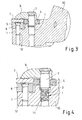
- FIGS. 1, 2 . 3, 4 show an inventive cutting tool 6 with attached cutting body adapter 4, in which a cutting body 7 (here an indexable insert) is inserted on a support plate 8.
- the attachment is made by a clamping claw 9. This is attached via a screw 2 on the cutting tool 6 and the carrier tool 10.
- this Spannpratzenschraubenharm is denoted by the reference numeral 11.
- the support plate 8 is attached via a screw 2 on the cutting tool 6 and the carrier tool 10. In the figures, this support plate attachment is indicated by the reference numeral 12.
- the cutting body adapter 4 is interchangeable and is received, held and guided in a suitable pocket or recess on the carrier tool 10.
- this Schneid stressesadapterbefest Trent is marked with the reference numeral 13.
- 4 holes are made in the cutting body adapter, are guided by the screws 2. These screws are screwed into threaded holes in the bottom, on which the cutting body adapter 4 is seated.
- the outer shape of the cutting body adapter 4 is adapted in its shape and orientation to the side walls of the pocket on the carrier tool 10.
- the inner shape of the adapter 1 is again a pocket or recess whose shape and orientation is such as required by the cutting body 7 to be used or the indexable insert.
- This pocket or recess is almost identical to the pockets or recesses on otherwise standard carrier tools without this cutting body adapter, which is located between the cutting body 7 and 10 carrier tool.
- the cutting body 7 is embedded at 3 mutually angled walls or surfaces and thus has no direct contact with the carrier tool 10th
- the cutting body 7 also referred to as cutting insert or indexable insert, introduced a trough, as shown in the WO 03/013770 A1
- the trough is circular in shape and has a spherical or circular elevation in the middle.
- the top of the survey is above the trough bottom and below the cutting top.
- a clamping claw 9 as a fastening means adapted to the trough shaped nose positively into the trough of the cutting body 7 a.
- This trough is used for form-fitting tension on the carrier tool.
- this cutting body 7 with the special trough offers.
- this trough see the cited document.
- threaded bores are made in the bottom, on which the cutting body adapter rests.
- the trough is formed as shown in FIG EP 1 536 903 B1 is described.
- a first clamping recess for clamping is introduced into the cutting tool and coaxially to the first clamping recess, a second clamping recess is arranged, wherein the first clamping recess are arranged lower than the second clamping recess and both lower than the cutting plate top.
- the clamping claw 9 rests on the second clamping recess and engages with a nose in the first clamping recess.
- the distance from the support surface of the clamping claw 9 to the trough is thus always constant and is not dependent on lapping or grinding operations of the cutting top surfaces.
- the cutting body 7 is made of PCBN or CBN. This is described in the WO 2005/021192 A1 ,
- the clamping trough may again be circular and have a spherical or circular elevation in the middle, as just described.
- the corresponding contour of the clamping trough is preferably introduced by laser machining or via a corresponding shaping of the green body and the green body thus produced is then dried and sintered.
- the screws 2 at least in the region of their thread 3 by coating on a smooth surface and the screw connection or the two threaded partners (screws and tapped holes) are lubricated with small amounts of a heat-resistant grease with ceramic powder particles.
- screw connections 1 include, for example, the Spannpratzenschrauben füren 11 (see FIG. 4 ), the support plate fasteners 12 (see FIGS. 3 and 4 ), the cutter body mount fasteners 13 (see Figures 1 and 2 ) or cassette and stab sword attachments.
Landscapes
- Chemical & Material Sciences (AREA)
- Engineering & Computer Science (AREA)
- Mechanical Engineering (AREA)
- General Chemical & Material Sciences (AREA)
- Chemical Kinetics & Catalysis (AREA)
- Organic Chemistry (AREA)
- Metallurgy (AREA)
- Materials Engineering (AREA)
- General Engineering & Computer Science (AREA)
- Dispersion Chemistry (AREA)
- Inorganic Chemistry (AREA)
- Oil, Petroleum & Natural Gas (AREA)
- Powder Metallurgy (AREA)
- Lubricants (AREA)
- Scissors And Nippers (AREA)
Description
- Die Erfindung beschreibt eine Verbesserung bestimmter Eigenschaften von Schraubenverbindungen mit Schrauben und zugehörenden Gewindebohrungen auf Zerspanungswerkzeugen, die zur Zerspanung von meist metallischen Werkstoffen dienen.
-
DE 10 2008 001 857 A1 beschreibt ein Zerspanungswerkzeug zur Aufnahme von Schneidplatten zur spanabhebenden Bearbeitung von metallischen Werkstücken, mit einer als Plattensitz ausgebildeten Ausnehmung mit Plattensitzwänden und einem Plattensitzboden zur Aufnahme der Schneidplatte, wobei die Schneidplatte Seitenflächen aufweist, die im Einbauzustand der Schneidplatte auf dem Zerspanungswerkzeug parallel zu den Plattensitzwänden angeordnet sind und die Schneidplatte durch Spannmittel im Plattensitz befestig ist. Auf dem Plattensitzboden ist eine Schneidkörperunterlage durch eine Schraube befestigt. Zur Verlängerung der Lebensdauer des Zerspanungswerkzeugs wird vorgeschlagen, dass zwischen einer Plattensitzwand und einer Seitenfläche der Schneidplatte ein austauschbares Einlegestück angeordnet ist. Dieses Einlegestück ist in einer Ausführungsform mit Schrauben am Zerspanungswerkzeug befestigt. Die Spannmitttel der Schneidplatte im Plattensitz umfassen eine Spannpratze, die über eine Befestigungsschraube am Zerspanungswerkzeug befestigt ist. An Zerspanungswerkzeugen werden somit verschiedene Verschraubungen benutzt. - Die wichtigste Schraubenverbindung auf Zerspanungswerkzeugen ist die Befestigungsschraube der Spannpratze, die den zerspanenden Schneideinsatz, Schneidkörper oder Schneidplatte klemmt. Bei der Zerspanung von z. B. Gusseisenwerkstoffen, ohne die Verwendung von Kühlschmiermitteln, wird bei der Materialabtrennung sehr viel Wärme erzeugt, die nicht vollständig über die Späne abgeführt wird, sondern auch über den Schneidkörper in das Trägerwerkzeug des Zerspanungswerkzeugs und in die Spannpratze und andere Spannmittel abgeführt wird. Nach längerer Einsatzzeit erhitzen sich die Bauteile sehr stark, die Schmierfette werden weich, können sich verflüchtigen und die Schmierwirkung lässt nach. Gussstaub und Späne werden zudem vom flüssigen Fett aufgenommen. Die gesamte Verbindung verschmutzt im Laufe der Zeit und neigt schließlich zum Verharzen und Verkleben. Zudem ist nach einer gewissen Zerspanungszeit ein Wechsel des Schneidkörpers notwendig, welches durch Lösen der Schraubenverbindung der Spannpratze, Wechseln oder Drehen des Schneidkörpers und erneutes Schließen der Schraubenverbindung durchgeführt wird. Es ist hierbei auch meist nicht zu vermeiden, dass zwangsläufig auch Schmutz in die Schraubenverbindung gelangt. Dieses führt dazu, dass die Gängigkeit der Schraubenverbindung im Laufe der Zeit nachlässt oder gänzlich ausfällt.
- Der Erfindung liegt die Aufgabe zugrunde, die Schraubenverbindungen so zu verbessern, dass die Verbindung nach langfristigem Einsatz in der Zerspanung unter extremen Einsatzbedingungen mit Schmutz, extremer Wärme, Feuchtigkeit, Oxidation und Wechsellasten problemlos und ohne überproportionalen Kraftaufwand wieder gelöst werden können.
- Erfindungsgemäß wird diese Aufgabe durch die Merkmale der Schraubenverbindungen gemäß dem Anspruch 1 sowie der Verwendung gemäß Anspruch 9 als auch des Verfahrens gemäß dem Anspruch 7 gelöst.
- Realisiert wird dieses durch die erfindungsgemäße Kombination und Verwendung von beschichteten, bevorzugt chemisch vernickelten Schrauben, und dadurch, dass die Schraubenverbindung bzw. die beiden Gewindepartner (Schrauben und Gewindebohrungen) mit geringen Mengen eines hitzbeständigen Fettes mit Keramikpulverpartikeln geschmiert sind. Die verwendeten Schrauben sind dabei zur Erzielung von Korrosionsbeständigkeit und Trockenschmiereigenschaften bevorzugt chemisch vernickelt und als Besonderheit sind in der Beschichtung zum Beispiel in der Nickelschicht zusätzlich PTFE (Polytetrafluorethylen) Partikel eingebettet. PTFE ist ein vollfluoriertes Polymer, welches allgemein unter dem Produktnamen Teflon von der Firma DuPont bekannt ist.
- Die Einbettung von PTFE Partikeln hat den Vorteil, dass im Unterschied zu aufgebrachten Schmierstoffen der niedrige Reibwert um 0,1 dank der sehr homogen eingelagerten PTFE-Partikel beispielsweise über die gesamte Nickelschicht erhalten bleibt. Selbst bei mikroskopisch kleinem Abrieb treten immer neue PTFE-Partikel an die Oberfläche und gewährleisten somit die Schmiereigenschaften über die gesamte Lebensdauer der Schicht,
- Diese Beschichtung mit Nickel unter Einlagerung von PTFE Partikeln wird auch als Nickel-PTFE-Dispersionsschicht bezeichnet, welche 20 - 30 Vol-% PTFE-Feinstpartikel in der Nickelmatrix eingelagert hat.
- Die Zuhilfenahme eines hitzbeständigen Fettes mit ungiftigen Keramikpulverbestandteilen als Notlaufeigenschaften optimieren durch die niedrigen Reibungswerte zudem diese Schraubenverbindung und bieten neben der leichten Lösbarkeit eine schmutzabweisende Eigenschaft, die die Lebensdauer und Montagefreundlichkeit der Schraubenverbindung vergrößert. Eine hohe Zuverlässigkeit der eingesetzten Bauteile und eine damit verbundene Kundenzufriedenheit sind die Folgen.
- Zum Stand der Technik gehört die Verwendung chemisch brünierter oder mit anderen Verfahren korrosionsbeständig gemachter Schrauben. Das chemische Vernickeln von Schrauben, Gewindestiften und anderen Konstruktionsbauteilen ist ein an sich bekannter Stand der Technik, deren Verwendung an Trägerwerkzeugen zur Zerspanung bzw. an Zerspanungswerkzeugen ist jedoch nicht bekannt. Die Verwendung von Schrauben, bei denen zusätzlich noch PTFE Partikel in der Nickelschicht eingebettet sind, ist bei Trägerwerkzeugen zur Zerspanung ebenfalls nicht bekannt. Das erfindungsgemäße Verfahren bietet zur Korrosionsbeständigkeit auch noch bessere Gleiteigenschaften der mechanischen Verbindungen.
- Zum Stand der Technik bei Schraubenverbindungen auf Zerspanungswerkzeugen gehört außerdem die Verwendung von warmfesten Fetten, die durch die Einbettung von meist Kupferpartikeln eine Notschmiereigenschaft bieten sollen. Diese kupferhaltigen Fette sind sehr warmfest. Die Kupferpartikel bieten Notschmiereigenschaften, die entstehen, wenn durch hohe Betriebstemperaturen von 100° bis 400° die Schmiereigenschaft des Fettes in der Schraubenverbindung nachlässt, bzw. nicht mehr vorhanden ist. Anwendung finden dieses Fette z. B. im Automobil zum gangbar halten des Bremsbelages im Bremssattel bei Scheibenbremsanlagen.
- Die Verwendung von chemisch vernickelten Bauteilen mit eingelagerten PTFE Partikeln, in Kombination mit einem hochwarmfesten Fett mit mikrofeinen Keramikpartikeln und dieses vorzugsweise genutzt bei Schraubenverbindungen, speziell bei Spannpratzen auf Zerspanungswerkzeugen, ist in dieser Funktionsweise neuartig. Es dient zur gezielten und kontrollierten Verminderung der Reibkräfte zwischen den einzelnen Bauteilen und besonders in der Schraubenverbindung. Diese Werkstoff- und Schmierstoffkombination zeichnet sich aus durch die hervorragenden Gleiteigenschaften und die im Langzeiteinsatz anhaltenden Notschmiereigenschaften. Zusätzlich wird durch die glatte Oberfläche der Beschichtung, sowie durch die Schmutz- und Feuchtigkeit abweisenden Eigenschaften des Fettes die Aufnahme von Schmutz und Späne, sowie eine Verharzung der Komponenten verhindert. Letztendlich ist ein Versagen der Funktionseigenschaften der Schraubenverbindung, auch unter schwierigen Einsatzbedingungen, vermeidbar. Die Lebensdauer dieser dynamischen Schraubenverbindung, die zusätzlich unter dem Einfluss von Zerspanungskräften, Wärme und Vibrationen stehen, wird heraufgesetzt. Die Wechselzyklen können verlängert werden, der Wartungsaufwand wird minimiert. Eine Kostensenkung durch sinkenden Bedarf an vorzeitig auszutauschenden Komponenten ist die Folge. Auch die Umweltbelastung durch geringere Verwendung von Schmierstoffen ist einer der Vorteile.
- Nachfolgend wird die Erfindung weiter anhand der Merkmale der Ansprüche beschrieben.
- Eine Schraubenverbindung mit Schrauben und zugehörenden Gewindebohrungen auf Zerspanungswerkzeugen ist erfindungsgemäß dadurch verbessert, dass die Schrauben zumindest im Bereich ihres Gewindes durch Beschichtung eine glatte Oberfläche aufweisen, in der Beschichtung PTFE Partikel, bevorzugt mit einer Partikelgröße zwischen 100 nm und 300 nm, enthalten sind und die Schraubenverbindung bzw. die beiden Gewindepartner (Schrauben und Gewindebohrungen) mit geringen Mengen eines hitzebeständigen Fettes mit Keramikpulverpartikeln geschmiert sind. Durch die glatte Beschichtung ist die Schraubenverbindung auch nach langem Gebrauch wieder zu lösen. Die PTFE Partikel gewährleisten die Schmiereigenschaften über die gesamte Lebensdauer der Schicht. Durch diese Maßnahmen kann die Schraubenverbindung mit einer Mindermengenschmierung versehen werden.
- Die Dicke der Beschichtung ist kleiner als 25 µm, bevorzugt kleiner als 10 µm und liegt besonders bevorzugt zwischen 3 µm und 7 µm. Die Gleitreibungskoeffizienten der Schrauben im beschichteten Bereich liegen bevorzugt zwischen 0,05 und 0,07.
- Die PTFE Partikel nehmen zwischen 20 und 30 Volumenprozent, bevorzugt 25 Volumenprozent an der Beschichtung ein. Hierdurch sind sowohl die Schmiereigenschaften als auch die Lösbarkeit der Schraubenverbindung in einem optimalen Verhältnis zueinander.
- In bevorzugter Ausführungsform ist oder wird die glatte Oberfläche der Schrauben durch chemisches Vernickeln unter gleichzeitiger Einbindung von PTFE Partikeln in die Nickelschicht erzeugt. Das Resultat ist eine Einfach-Dispersionsschicht, welche die Härte des Nickels und die Gleiteigenschaften des PTFE in sich vereinigt. Eine Nickel-PTFE-Dispersionsschicht, welche ca. 25 Vol.-% PTFE Feinstpartikel in der Nickelmatrix eingelagert hat, gehört zum Stand der Technik.
- In einer Ausführungsform ist in der Beschichtung Phosphor, bevorzugt 1 Gewichtsprozent Phosphor, enthalten.
- Erfindungsgemäß sind die Schraubenverbindungen bzw. die beiden Gewindepartner (Schrauben und Gewindebohrungen) mit geringen Mengen eines Fettes mit Keramikpartikeln geschmiert.
- Ein Verfahren zur Verbesserung der Schraubenverbindungen mit Schrauben und zugehörenden Gewindebohrungen auf Zerspanungswerkzeugen besteht darin, dass die Schrauben zumindest im Bereich ihres Gewindes beschichtet werden um eine glatte Oberfläche zu erhalten, in die Beschichtung PTFE Partikel, bevorzugt mit einer Partikelgröße zwischen 100 nm und 300 nm, eingebunden werden und die Schraubenverbindung bzw. die beiden Gewindepartner (Schrauben und Gewindebohrungen) mit geringen Mengen eines hitzebeständigen Fettes mit Keramikpulverpartikeln geschmiert sind.
- In spezieller Ausführungsform werden die verwendeten Schrauben zur Beschichtung chemisch vernickelt unter gleichzeitiger Einbindung von PTFE Partikeln in die Nickelschicht und die Gewindepartner der Schraubenverbindungen mit einem hitzebeständigen Fett mit Keramikpulverbestandteilen geschmiert.
- Die Erfindung bezieht sich auch auf einer Verwendung von zumindest im Gewindebereich beschichteten Schrauben, die in der Beschichtung PTFE Partikel aufweisen und mit geringen Mengen eines hitzebeständigen Fettes mit Keramikpulverpartikeln geschmiert sind, in Schraubenverbindungen auf Zerspanungswerkzeugen.
- Bevorzugt in der Verwendung ist, dass chemisch vernickelte Schrauben verwendet werden, die in der Nickelschicht PTFE Partikel aufweisen.
- Vorteilhaft wird zur Schmierung der Schraubenverbindungen hitzebeständiges Fett mit Keramikpulverbestandteilen verwendet.
- Ein Zerspanungswerkzeug mit über Schraubenverbindungen befestigten Bauteilen und Schmierung der Gewindepartner dieser Schraubenverbindungen mit einem Fett besteht darin, dass die Schrauben der Schraubenverbindungen beschichtet sind und in der Beschichtung eingebettete PTFE Partikel aufweisen und die Gewindepartner der Schraubenverbindungen mit einem hitzebeständigen Fett mit Keramikpulverbestandteilen geschmiert sind.
- Bevorzugt sind zur Beschichtung die Schrauben der Schraubenverbindungen chemisch vernickelt und weisen in der Nickelschicht eingebettete PTFE Partikel auf.
- Schrauben zur Befestigung von Bauteilen an Zerspanungswerkzeugen sind unter gleichzeitiger Einbindung von PTFE Partikeln in der Beschichtung beschichtet.
- Bevorzugt sind die Schrauben chemisch vernickelt unter gleichzeitiger Einbindung von PTFE Partikeln in der Nickelschicht.
- Ein Fett zur Schmierung von Schraubenverbindungen auf Zerspanungswerkzeugen ist hitzebeständig und mit Keramikpulverbestandteilen versehen.
- Die Schraubenverbindungen, das Verfahren zur Verbesserung der Schraubenverbindungen, die Verwendung, das Zerspanungswerkzeug und die Schrauben sind derart ausgeführt, dass die Schraubenverbindungen die Spannpratzenschraubenverbindungen, die Stützplattenbefestigungen, die Schneidkörperadapterbefestigung oder Kassetten- und Stechschwertbefestigungen umfassen.
- Nachfolgend wird die Erfindung anhand eines Ausführungsbeispiels in verschiedenen Figuren als Ansichten und Schnitten weiter erläutert.
- Die
Figuren 1, 2 ,3, 4 zeigen ein erfindungsgemäßes Zerspanungswerkzeug 6 mit aufgesetztem Schneidkörperadapter 4, in dem ein Schneidkörper 7 (hier eine Wendeschneidplatte) auf einer Stützplatte 8 eingesetzt ist. Die Befestigung erfolgt über eine Spannpratze 9. Diese ist über eine Schraube 2 auf dem Zerspanungswerkzeug 6 bzw. dem Trägerwerkzeug 10 befestigt. In den Figuren ist diese Spannpratzenschraubenverbindung mit dem Bezugszeichen 11 gekennzeichnet. Auch die Stützplatte 8 ist über eine Schraube 2 auf dem Zerspanungswerkzeug 6 bzw. dem Trägerwerkzeug 10 befestigt. In den Figuren ist diese Stützplattenbefestigung mit dem Bezugszeichen 12 gekennzeichnet. - Der Schneidkörperadapter 4 ist auswechselbar und ist in einer dafür geeigneten Tasche oder Ausnehmung auf dem Trägerwerkzeug 10 aufgenommen, gehalten und geführt. In den Figuren ist diese Schneidkörperadapterbefestigung mit dem Bezugszeichen 13 gekennzeichnet. Hierzu sind im Schneidkörperadapter 4 Bohrungen eingebracht, durch die Schrauben 2 geführt sind. Diese Schrauben sind in Gewindebohrungen im Boden, auf dem der Schneidkörperadapter 4 aufsitzt, eingeschraubt. Die Außenform des Schneidkörperadapters 4 ist dabei in seiner Form und Ausrichtung den Seitenwänden der Tasche auf dem Trägerwerkzeug 10 angepasst. Die Innenform des Adapters 1 ist wiederum eine Tasche oder Ausnehmung, dessen Form und Ausrichtung so beschaffen ist, wie es der zu verwendende Schneidkörper 7, bzw. die Wendeschneidplatte erfordert. Diese Tasche oder Ausnehmung ist nahezu identisch mit den Taschen oder Ausnehmungen auf sonst handelsüblichen Trägerwerkzeugen ohne diesen Schneidkörperadapter, welcher sich zwischen Schneidkörper 7 und Trägerwerkzeug 10 befindet. Der Schneidkörper 7 wird dabei an 3 zueinander winkelig stehenden Wänden oder Flächen eingebettet und hat hierdurch keinen direkten Kontakt mehr zum Trägerwerkzeug 10.
- Wie in den
Figuren 3 und 4 gezeigt, ist in dem Schneidkörper 7, auch als Schneidplatte oder Wendeschneidplatte bezeichnet, eine Mulde eingebracht, wie sie in derWO 03/013770 A1 - Zur Befestigung des Schneidkörperadapters 4 in der Tasche des Trägerwerkzeugs 10 mittels Schrauben sind im Boden, auf dem der Schneidkörperadapter aufliegt, Gewindebohrungen eingebracht.
- Damit Läpp- oder Schleifbearbeitungen der Schneidkörperoberseiten die Klemmeigenschaften des Schneidkörpers 7 nicht beeinflussen, ist in einer Ausführungsform die Mulde so ausgebildet, wie es in der
EP 1 536 903 B1 beschrieben ist. In diesem Fall ist eine erste Spannmulde zum Einspannen in das Schneidwerkzeug eingebracht und ist koaxial zur ersten Spannmulde eine zweite Spannmulde angeordnet, wobei die erste Spannmulde tiefer als die zweite Spannmulde und beide tiefer als die Schneidplattenoberseite angeordnet sind. Beim Klemmen des Schneidkörpers 7 liegt die Spannpratze 9 auf der zweiten Spannmulde auf und greift mit einer Nase in die erste Spannmulde ein. Der Abstand von der Auflagefläche der Spannpratze 9 zur Mulde ist damit immer konstant und ist nicht abhängig von Läpp- oder Schleifbearbeitungen der Schneidplattenoberseiten. - In einer Ausführungsform besteht der Schneidkörper 7 aus PCBN oder aus CBN. Beschrieben ist dies in der
WO 2005/021192 A1 . Die Spannmulde kann wieder kreisförmig ausgebildet sein und in der Mitte eine kugel- bzw. kreisförmige Erhebung aufweisen, wie eben beschrieben. Die entsprechende Kontur der Spannmulde ist bevorzugt durch Laserbearbeitung oder über eine entsprechende Formgebung des Grünkörpers eingebracht und der so hergestellte Grünkörper wird dann getrocknet und gesintert. - Erfindungsgemäß weisen die Schrauben 2 zumindest im Bereich ihres Gewinde 3 durch Beschichtung eine glatte Oberfläche auf und sind die Schraubenverbindung bzw. die beiden Gewindepartner (Schrauben und Gewindebohrungen) mit geringen Mengen eines hitzebeständigen Fettes mit Keramikpulverpartikeln geschmiert sind.
- Diese Schraubenverbindungen 1 umfassen zum Beispiel die Spannpratzenschraubenverbindungen 11 (siehe
Figur 4 ), die Stützplattenbefestigungen 12 (sieheFiguren 3 und 4 ), die Schneidkörperadapterbefestigungen 13 (sieheFiguren 1 und 2 ) oder Kassetten- und Stechschwertbefestigungen.
Claims (11)
- Schraubenverbindungen (1) mit Schrauben (2) und zugehörenden Gewindebohrungen auf Zerspanungswerkzeugen (6), dadurch gekennzeichnet, dass die Schrauben (2) zumindest im Bereich ihres Gewindes (3) durch Beschichtung eine glatte Oberfläche aufweisen, in der Beschichtung PTFE Partikel, bevorzugt mit einer Partikelgröße zwischen 100 nm und 300 nm, enthalten sind und die Schraubenverbindung (1) bzw. die beiden Gewindepartner bildenden Schrauben und Gewindebohrungen mit geringen Mengen eines hitzebeständigen Fettes mit Keramikpulverpartikeln geschmiert sind.
- Schraubenverbindungen nach Anspruch 1, dadurch gekennzeichnet, dass die Dicke der Beschichtung kleiner als 25 µm, bevorzugt kleiner als 10 µm ist und besonders bevorzugt zwischen 3 µm und 7 µm liegt.
- Schraubenverbindungen nach Anspruch 1 oder 2, dadurch gekennzeichnet, dass die Gleitreibungskoeffizienten der Schrauben im beschichteten Bereich zwischen 0,05 und 0,07 liegt.
- Schraubenverbindungen nach einem der Ansprüche 1 bis 3, dadurch gekennzeichnet, dass die PTFE Partikel zwischen 20 und 30 Volumenprozent, bevorzugt 25 Volumenprozent an der Beschichtung einnehmen.
- Schraubenverbindungen nach einem der Ansprüche 1 bis 4, dadurch gekennzeichnet, dass die glatte Oberfläche der Schrauben (2) durch chemisches Vernickeln unter gleichzeitigem Einbindung von PTFE Partikeln in die Nickelschicht erzeugt ist.
- Schraubenverbindungen nach einem der Ansprüche 1 bis 5, dadurch gekennzeichnet, dass in der Beschichtung Phosphor, bevorzugt 1 Gewichtsprozent, enthalten ist.
- Verfahren zur Verbesserung der Schraubenverbindungen (1) mit Schrauben (2) und zugehörenden Gewindebohrungen auf Zerspanungswerkzeugen (6), dadurch gekennzeichnet, dass die Schrauben (2) zumindest im Bereich ihres Gewindes (3) beschichtet werden um eine glatte Oberfläche zu erhalten, in die Beschichtung PTFE Partikel, bevorzugt mit einer Partikelgröße zwischen 100 nm und 300 nm, eingebunden werden und die Schraubenverbindung (1) bzw. die beiden Gewindepartner bildenden Schrauben und Gewindebohrungen mit geringen Mengen eines hitzebeständigen Fettes mit Keramikpulverpartikeln geschmiert sind.
- Verfahren nach Anspruch 7, dadurch gekennzeichnet, dass die verwendeten Schrauben (2) zur Beschichtung chemisch vernickelt werden unter gleichzeitiger Einbindung von PTFE Partikeln in die Nickelschicht.
- Verwendung von zumindest im Gewindebereich beschichteten Schrauben (2), die in der Beschichtung PTFE Partikel aufweisen und mit geringen Mengen eines hitzebeständigen Fettes mit Keramikpulverpartikeln geschmiert sind, in Schraubenverbindungen (1) auf Zerspanungswerkzeugen (6).
- Verwendung nach Anspruch 9, dadurch gekennzeichnet, dass chemisch vernickelte Schrauben verwendet werden, die in der Nickelschicht PTFE Partikel aufweisen.
- Verwendung nach Anspruch 9 oder 10, dadurch gekennzeichnet, dass zur Schmierung der Schraubenverbindungen (1) hitzebeständiges Fett mit Keramikpulverbestandteilen verwendet wird.
Priority Applications (1)
| Application Number | Priority Date | Filing Date | Title |
|---|---|---|---|
| PL10714292T PL2421670T3 (pl) | 2009-04-21 | 2010-04-20 | Połączenia śrubowe na narzędziach skrawających |
Applications Claiming Priority (2)
| Application Number | Priority Date | Filing Date | Title |
|---|---|---|---|
| DE102009002535 | 2009-04-21 | ||
| PCT/EP2010/055197 WO2010122022A1 (de) | 2009-04-21 | 2010-04-20 | Schraubenverbindungen auf zerspanungswerkzeugen |
Publications (2)
| Publication Number | Publication Date |
|---|---|
| EP2421670A1 EP2421670A1 (de) | 2012-02-29 |
| EP2421670B1 true EP2421670B1 (de) | 2014-06-11 |
Family
ID=42224876
Family Applications (1)
| Application Number | Title | Priority Date | Filing Date |
|---|---|---|---|
| EP10714292.9A Not-in-force EP2421670B1 (de) | 2009-04-21 | 2010-04-20 | Schraubenverbindungen auf Zerspanungswerkzeugen |
Country Status (8)
| Country | Link |
|---|---|
| US (1) | US20120141216A1 (de) |
| EP (1) | EP2421670B1 (de) |
| BR (1) | BRPI1016157A2 (de) |
| DE (1) | DE102010027988A1 (de) |
| ES (1) | ES2500925T3 (de) |
| MX (1) | MX2011011104A (de) |
| PL (1) | PL2421670T3 (de) |
| WO (1) | WO2010122022A1 (de) |
Families Citing this family (6)
| Publication number | Priority date | Publication date | Assignee | Title |
|---|---|---|---|---|
| US8727674B2 (en) * | 2012-02-16 | 2014-05-20 | Kennametal Inc. | Tool holder with nubs for clamping a cutting insert with notches |
| JP5988822B2 (ja) * | 2012-10-19 | 2016-09-07 | 株式会社フジキン | 管継手 |
| DE202014102663U1 (de) | 2014-06-06 | 2014-06-24 | Ti Automotive (Heidelberg) Gmbh | Schraubelement für den Anschluss von Rohrleitungen und Rohranschlusseinrichtung mit diesem Schraubelement |
| US20160016233A1 (en) * | 2014-07-17 | 2016-01-21 | Kennametal India Limited | Notched cutting inserts and applications thereof |
| CN104816013B (zh) * | 2015-05-15 | 2019-01-15 | 杨帆 | 一种碾米砂辊通风孔钻头及钻孔设备 |
| US10052694B2 (en) * | 2016-05-04 | 2018-08-21 | Kennametal Inc. | Apparatus and method for cooling a cutting tool using super critical carbon dioxide |
Family Cites Families (16)
| Publication number | Priority date | Publication date | Assignee | Title |
|---|---|---|---|---|
| US2173004A (en) * | 1937-01-21 | 1939-09-12 | Clare L Brackett | Antiseizing screw threaded unit |
| US2263527A (en) * | 1940-02-09 | 1941-11-18 | Reed & Prince Mfg Company | Fastening device and process |
| DE3604104A1 (de) * | 1986-02-10 | 1987-08-13 | Dow Corning Gmbh | Hochtemperatur-schraubenschmierpaste |
| GB2233982B (en) * | 1989-05-08 | 1993-10-13 | Wear Cote Int | Co-deposition of fluorinated carbon with electroless nickel |
| US5792727A (en) * | 1990-05-16 | 1998-08-11 | Jacobs; Norman Laurie | Lubricant compositions |
| AU2001236086A1 (en) * | 2001-03-05 | 2002-03-13 | Gotoh Gut Co., Ltd. | Chord winder for stringed instrument |
| WO2002073590A1 (en) * | 2001-03-05 | 2002-09-19 | Gotoh Gut Co., Ltd. | Metal components for string instrument |
| DE10208266A1 (de) | 2001-07-26 | 2003-02-13 | Ceram Tec Ag Innovative Cerami | Spanabhebendes Schneidwerkzeug und Schneidplatte in Donut-Form |
| DE10237472A1 (de) * | 2002-08-16 | 2004-02-26 | Km Europa Metal Ag | Flüssigkeitsgekühlte Kokille |
| DE10239451A1 (de) * | 2002-08-28 | 2004-03-11 | Ceramtec Ag Innovative Ceramic Engineering | Schneidplatte mit Doppelmulde |
| US20090035521A1 (en) | 2003-08-22 | 2009-02-05 | Andreas Hafner | Die consisting of PCBN or a CBN composite material comprising a clamping depression |
| DE102004034246B4 (de) * | 2004-07-15 | 2008-04-24 | Sfs Intec Holding Ag | Schraube |
| GB2433770A (en) * | 2005-12-29 | 2007-07-04 | Thales Holdings Uk Plc | Hinge with clamped pin coated with hardness imparting component |
| US7781382B2 (en) * | 2006-12-01 | 2010-08-24 | Napra Co., Ltd. | Lubricant composition and bearing structure |
| US20080269086A1 (en) * | 2007-04-30 | 2008-10-30 | Atanu Adhvaryu | Functionalized nanosphere lubricants |
| EP1995007A1 (de) | 2007-05-22 | 2008-11-26 | CeramTec AG | Plattensitz mit Einlegestücken |
-
2010
- 2010-04-20 EP EP10714292.9A patent/EP2421670B1/de not_active Not-in-force
- 2010-04-20 US US13/264,781 patent/US20120141216A1/en not_active Abandoned
- 2010-04-20 MX MX2011011104A patent/MX2011011104A/es unknown
- 2010-04-20 DE DE102010027988A patent/DE102010027988A1/de not_active Withdrawn
- 2010-04-20 PL PL10714292T patent/PL2421670T3/pl unknown
- 2010-04-20 ES ES10714292.9T patent/ES2500925T3/es active Active
- 2010-04-20 BR BRPI1016157A patent/BRPI1016157A2/pt not_active Application Discontinuation
- 2010-04-20 WO PCT/EP2010/055197 patent/WO2010122022A1/de not_active Ceased
Also Published As
| Publication number | Publication date |
|---|---|
| WO2010122022A1 (de) | 2010-10-28 |
| EP2421670A1 (de) | 2012-02-29 |
| MX2011011104A (es) | 2012-02-22 |
| PL2421670T3 (pl) | 2015-01-30 |
| US20120141216A1 (en) | 2012-06-07 |
| BRPI1016157A2 (pt) | 2016-04-19 |
| DE102010027988A1 (de) | 2010-10-28 |
| ES2500925T3 (es) | 2014-10-01 |
Similar Documents
| Publication | Publication Date | Title |
|---|---|---|
| EP0921211B1 (de) | Schichtverbundwerkstoff für Gleitlanger mit bleifreier Gleitschicht | |
| EP2421670A1 (de) | Schraubenverbindungen auf zerspanungswerkzeugen | |
| DE102013214012B4 (de) | Gleitlager | |
| EP2931519B1 (de) | Gleitlagerverbundwerkstoff | |
| DE69519009T2 (de) | Gesintertes Kontaktbauteil | |
| DE102008038635B4 (de) | Kolbenring | |
| WO1997003299A1 (de) | Gleitlagerwerkstoff und dessen verwendung | |
| DE10312479A1 (de) | Scheibenbremse | |
| DE102008055194A1 (de) | Gleitelement | |
| EP0832155B1 (de) | Gleitschichtmaterial | |
| AT511432B1 (de) | Verfahren zur herstellung eines gleitlagerelementes | |
| DE112010005433T5 (de) | Gleitelement und Verfahren zur Herstellung desselben | |
| DE102006045749A1 (de) | Ventil und Verfahren zur Herstellung desselben | |
| DE10226266A1 (de) | Gleitlagerverbundwerkstoff | |
| DE10312480A1 (de) | Scheibenbremse mit auf Bolzen geführten Bremsbelägen | |
| DE102017216110A1 (de) | Gleitlack, Gleitelement mit einem solchen und dessen Verwendung | |
| DE102020200149A1 (de) | Gleitlager mit verbesserter Verschleißfestigkeit | |
| EP2850329B1 (de) | Gleitlagerverbundwerkstoff | |
| DE112016000629B4 (de) | Verbindungsvorrichtung für fluidische Vorrichtungen | |
| EP1523598B1 (de) | Gleitlager für das bauwesen und werkstoff hierfür | |
| DE10312478A1 (de) | Scheibenbremse | |
| EP1933022B1 (de) | Kolben für eine Brennkraftmaschine | |
| DE69414488T2 (de) | Gesintertes Kontaktbauteil, sowie Verfahren seiner Herstellung | |
| DE60200779T2 (de) | Linearführungsapparat | |
| DE10126463A1 (de) | Gleitlagerverbundwerkstoff mit einer metallischen Stützschicht |
Legal Events
| Date | Code | Title | Description |
|---|---|---|---|
| PUAI | Public reference made under article 153(3) epc to a published international application that has entered the european phase |
Free format text: ORIGINAL CODE: 0009012 |
|
| 17P | Request for examination filed |
Effective date: 20111121 |
|
| AK | Designated contracting states |
Kind code of ref document: A1 Designated state(s): AT BE BG CH CY CZ DE DK EE ES FI FR GB GR HR HU IE IS IT LI LT LU LV MC MK MT NL NO PL PT RO SE SI SK SM TR |
|
| DAX | Request for extension of the european patent (deleted) | ||
| 17Q | First examination report despatched |
Effective date: 20120807 |
|
| RIC1 | Information provided on ipc code assigned before grant |
Ipc: F16B 33/06 20060101ALI20130719BHEP Ipc: C10M 103/06 20060101ALI20130719BHEP Ipc: C23C 18/32 20060101ALI20130719BHEP Ipc: C23C 18/16 20060101ALI20130719BHEP Ipc: C10M 113/08 20060101ALI20130719BHEP Ipc: B23B 27/16 20060101AFI20130719BHEP |
|
| GRAP | Despatch of communication of intention to grant a patent |
Free format text: ORIGINAL CODE: EPIDOSNIGR1 |
|
| INTG | Intention to grant announced |
Effective date: 20131126 |
|
| GRAS | Grant fee paid |
Free format text: ORIGINAL CODE: EPIDOSNIGR3 |
|
| GRAA | (expected) grant |
Free format text: ORIGINAL CODE: 0009210 |
|
| AK | Designated contracting states |
Kind code of ref document: B1 Designated state(s): AT BE BG CH CY CZ DE DK EE ES FI FR GB GR HR HU IE IS IT LI LT LU LV MC MK MT NL NO PL PT RO SE SI SK SM TR |
|
| REG | Reference to a national code |
Ref country code: GB Ref legal event code: FG4D Free format text: NOT ENGLISH |
|
| REG | Reference to a national code |
Ref country code: CH Ref legal event code: EP |
|
| REG | Reference to a national code |
Ref country code: IE Ref legal event code: FG4D Free format text: LANGUAGE OF EP DOCUMENT: GERMAN |
|
| REG | Reference to a national code |
Ref country code: AT Ref legal event code: REF Ref document number: 671991 Country of ref document: AT Kind code of ref document: T Effective date: 20140715 |
|
| REG | Reference to a national code |
Ref country code: DE Ref legal event code: R096 Ref document number: 502010007184 Country of ref document: DE Effective date: 20140724 |
|
| REG | Reference to a national code |
Ref country code: ES Ref legal event code: FG2A Ref document number: 2500925 Country of ref document: ES Kind code of ref document: T3 Effective date: 20141001 |
|
| REG | Reference to a national code |
Ref country code: SE Ref legal event code: TRGR |
|
| PG25 | Lapsed in a contracting state [announced via postgrant information from national office to epo] |
Ref country code: GR Free format text: LAPSE BECAUSE OF FAILURE TO SUBMIT A TRANSLATION OF THE DESCRIPTION OR TO PAY THE FEE WITHIN THE PRESCRIBED TIME-LIMIT Effective date: 20140912 Ref country code: FI Free format text: LAPSE BECAUSE OF FAILURE TO SUBMIT A TRANSLATION OF THE DESCRIPTION OR TO PAY THE FEE WITHIN THE PRESCRIBED TIME-LIMIT Effective date: 20140611 Ref country code: LT Free format text: LAPSE BECAUSE OF FAILURE TO SUBMIT A TRANSLATION OF THE DESCRIPTION OR TO PAY THE FEE WITHIN THE PRESCRIBED TIME-LIMIT Effective date: 20140611 Ref country code: NO Free format text: LAPSE BECAUSE OF FAILURE TO SUBMIT A TRANSLATION OF THE DESCRIPTION OR TO PAY THE FEE WITHIN THE PRESCRIBED TIME-LIMIT Effective date: 20140911 |
|
| REG | Reference to a national code |
Ref country code: NL Ref legal event code: VDEP Effective date: 20140611 |
|
| REG | Reference to a national code |
Ref country code: LT Ref legal event code: MG4D |
|
| PG25 | Lapsed in a contracting state [announced via postgrant information from national office to epo] |
Ref country code: LV Free format text: LAPSE BECAUSE OF FAILURE TO SUBMIT A TRANSLATION OF THE DESCRIPTION OR TO PAY THE FEE WITHIN THE PRESCRIBED TIME-LIMIT Effective date: 20140611 Ref country code: HR Free format text: LAPSE BECAUSE OF FAILURE TO SUBMIT A TRANSLATION OF THE DESCRIPTION OR TO PAY THE FEE WITHIN THE PRESCRIBED TIME-LIMIT Effective date: 20140611 |
|
| PG25 | Lapsed in a contracting state [announced via postgrant information from national office to epo] |
Ref country code: SK Free format text: LAPSE BECAUSE OF FAILURE TO SUBMIT A TRANSLATION OF THE DESCRIPTION OR TO PAY THE FEE WITHIN THE PRESCRIBED TIME-LIMIT Effective date: 20140611 Ref country code: CZ Free format text: LAPSE BECAUSE OF FAILURE TO SUBMIT A TRANSLATION OF THE DESCRIPTION OR TO PAY THE FEE WITHIN THE PRESCRIBED TIME-LIMIT Effective date: 20140611 Ref country code: RO Free format text: LAPSE BECAUSE OF FAILURE TO SUBMIT A TRANSLATION OF THE DESCRIPTION OR TO PAY THE FEE WITHIN THE PRESCRIBED TIME-LIMIT Effective date: 20140611 Ref country code: PT Free format text: LAPSE BECAUSE OF FAILURE TO SUBMIT A TRANSLATION OF THE DESCRIPTION OR TO PAY THE FEE WITHIN THE PRESCRIBED TIME-LIMIT Effective date: 20141013 Ref country code: EE Free format text: LAPSE BECAUSE OF FAILURE TO SUBMIT A TRANSLATION OF THE DESCRIPTION OR TO PAY THE FEE WITHIN THE PRESCRIBED TIME-LIMIT Effective date: 20140611 |
|
| REG | Reference to a national code |
Ref country code: PL Ref legal event code: T3 |
|
| PG25 | Lapsed in a contracting state [announced via postgrant information from national office to epo] |
Ref country code: IS Free format text: LAPSE BECAUSE OF FAILURE TO SUBMIT A TRANSLATION OF THE DESCRIPTION OR TO PAY THE FEE WITHIN THE PRESCRIBED TIME-LIMIT Effective date: 20141011 Ref country code: NL Free format text: LAPSE BECAUSE OF FAILURE TO SUBMIT A TRANSLATION OF THE DESCRIPTION OR TO PAY THE FEE WITHIN THE PRESCRIBED TIME-LIMIT Effective date: 20140611 |
|
| REG | Reference to a national code |
Ref country code: DE Ref legal event code: R097 Ref document number: 502010007184 Country of ref document: DE |
|
| PLBE | No opposition filed within time limit |
Free format text: ORIGINAL CODE: 0009261 |
|
| STAA | Information on the status of an ep patent application or granted ep patent |
Free format text: STATUS: NO OPPOSITION FILED WITHIN TIME LIMIT |
|
| REG | Reference to a national code |
Ref country code: FR Ref legal event code: PLFP Year of fee payment: 6 |
|
| PG25 | Lapsed in a contracting state [announced via postgrant information from national office to epo] |
Ref country code: DK Free format text: LAPSE BECAUSE OF FAILURE TO SUBMIT A TRANSLATION OF THE DESCRIPTION OR TO PAY THE FEE WITHIN THE PRESCRIBED TIME-LIMIT Effective date: 20140611 |
|
| 26N | No opposition filed |
Effective date: 20150312 |
|
| PGFP | Annual fee paid to national office [announced via postgrant information from national office to epo] |
Ref country code: PL Payment date: 20150325 Year of fee payment: 6 |
|
| REG | Reference to a national code |
Ref country code: DE Ref legal event code: R097 Ref document number: 502010007184 Country of ref document: DE Effective date: 20150312 |
|
| PG25 | Lapsed in a contracting state [announced via postgrant information from national office to epo] |
Ref country code: SI Free format text: LAPSE BECAUSE OF FAILURE TO SUBMIT A TRANSLATION OF THE DESCRIPTION OR TO PAY THE FEE WITHIN THE PRESCRIBED TIME-LIMIT Effective date: 20140611 |
|
| PGFP | Annual fee paid to national office [announced via postgrant information from national office to epo] |
Ref country code: SE Payment date: 20150420 Year of fee payment: 6 Ref country code: GB Payment date: 20150420 Year of fee payment: 6 Ref country code: ES Payment date: 20150427 Year of fee payment: 6 |
|
| PGFP | Annual fee paid to national office [announced via postgrant information from national office to epo] |
Ref country code: FR Payment date: 20150421 Year of fee payment: 6 Ref country code: IT Payment date: 20150422 Year of fee payment: 6 |
|
| REG | Reference to a national code |
Ref country code: DE Ref legal event code: R119 Ref document number: 502010007184 Country of ref document: DE |
|
| PG25 | Lapsed in a contracting state [announced via postgrant information from national office to epo] |
Ref country code: MC Free format text: LAPSE BECAUSE OF FAILURE TO SUBMIT A TRANSLATION OF THE DESCRIPTION OR TO PAY THE FEE WITHIN THE PRESCRIBED TIME-LIMIT Effective date: 20140611 Ref country code: LU Free format text: LAPSE BECAUSE OF FAILURE TO SUBMIT A TRANSLATION OF THE DESCRIPTION OR TO PAY THE FEE WITHIN THE PRESCRIBED TIME-LIMIT Effective date: 20150420 |
|
| REG | Reference to a national code |
Ref country code: CH Ref legal event code: PL |
|
| REG | Reference to a national code |
Ref country code: IE Ref legal event code: MM4A |
|
| PG25 | Lapsed in a contracting state [announced via postgrant information from national office to epo] |
Ref country code: CH Free format text: LAPSE BECAUSE OF NON-PAYMENT OF DUE FEES Effective date: 20150430 Ref country code: LI Free format text: LAPSE BECAUSE OF NON-PAYMENT OF DUE FEES Effective date: 20150430 Ref country code: DE Free format text: LAPSE BECAUSE OF NON-PAYMENT OF DUE FEES Effective date: 20151103 |
|
| PG25 | Lapsed in a contracting state [announced via postgrant information from national office to epo] |
Ref country code: IE Free format text: LAPSE BECAUSE OF NON-PAYMENT OF DUE FEES Effective date: 20150420 |
|
| REG | Reference to a national code |
Ref country code: AT Ref legal event code: MM01 Ref document number: 671991 Country of ref document: AT Kind code of ref document: T Effective date: 20150420 |
|
| PG25 | Lapsed in a contracting state [announced via postgrant information from national office to epo] |
Ref country code: AT Free format text: LAPSE BECAUSE OF NON-PAYMENT OF DUE FEES Effective date: 20150420 |
|
| REG | Reference to a national code |
Ref country code: SE Ref legal event code: EUG |
|
| GBPC | Gb: european patent ceased through non-payment of renewal fee |
Effective date: 20160420 |
|
| PG25 | Lapsed in a contracting state [announced via postgrant information from national office to epo] |
Ref country code: MT Free format text: LAPSE BECAUSE OF FAILURE TO SUBMIT A TRANSLATION OF THE DESCRIPTION OR TO PAY THE FEE WITHIN THE PRESCRIBED TIME-LIMIT Effective date: 20140611 |
|
| REG | Reference to a national code |
Ref country code: FR Ref legal event code: ST Effective date: 20161230 |
|
| PG25 | Lapsed in a contracting state [announced via postgrant information from national office to epo] |
Ref country code: FR Free format text: LAPSE BECAUSE OF NON-PAYMENT OF DUE FEES Effective date: 20160502 Ref country code: GB Free format text: LAPSE BECAUSE OF NON-PAYMENT OF DUE FEES Effective date: 20160420 |
|
| PG25 | Lapsed in a contracting state [announced via postgrant information from national office to epo] |
Ref country code: IT Free format text: LAPSE BECAUSE OF NON-PAYMENT OF DUE FEES Effective date: 20160420 Ref country code: SE Free format text: LAPSE BECAUSE OF NON-PAYMENT OF DUE FEES Effective date: 20160421 |
|
| PG25 | Lapsed in a contracting state [announced via postgrant information from national office to epo] |
Ref country code: HU Free format text: LAPSE BECAUSE OF FAILURE TO SUBMIT A TRANSLATION OF THE DESCRIPTION OR TO PAY THE FEE WITHIN THE PRESCRIBED TIME-LIMIT; INVALID AB INITIO Effective date: 20100420 Ref country code: BG Free format text: LAPSE BECAUSE OF FAILURE TO SUBMIT A TRANSLATION OF THE DESCRIPTION OR TO PAY THE FEE WITHIN THE PRESCRIBED TIME-LIMIT Effective date: 20140611 Ref country code: SM Free format text: LAPSE BECAUSE OF FAILURE TO SUBMIT A TRANSLATION OF THE DESCRIPTION OR TO PAY THE FEE WITHIN THE PRESCRIBED TIME-LIMIT Effective date: 20140611 |
|
| PG25 | Lapsed in a contracting state [announced via postgrant information from national office to epo] |
Ref country code: CY Free format text: LAPSE BECAUSE OF FAILURE TO SUBMIT A TRANSLATION OF THE DESCRIPTION OR TO PAY THE FEE WITHIN THE PRESCRIBED TIME-LIMIT Effective date: 20140611 |
|
| PG25 | Lapsed in a contracting state [announced via postgrant information from national office to epo] |
Ref country code: BE Free format text: LAPSE BECAUSE OF NON-PAYMENT OF DUE FEES Effective date: 20150430 |
|
| PG25 | Lapsed in a contracting state [announced via postgrant information from national office to epo] |
Ref country code: PL Free format text: LAPSE BECAUSE OF NON-PAYMENT OF DUE FEES Effective date: 20160420 |
|
| PGFP | Annual fee paid to national office [announced via postgrant information from national office to epo] |
Ref country code: TR Payment date: 20150420 Year of fee payment: 6 |
|
| PG25 | Lapsed in a contracting state [announced via postgrant information from national office to epo] |
Ref country code: ES Free format text: LAPSE BECAUSE OF NON-PAYMENT OF DUE FEES Effective date: 20160421 |
|
| PG25 | Lapsed in a contracting state [announced via postgrant information from national office to epo] |
Ref country code: MK Free format text: LAPSE BECAUSE OF FAILURE TO SUBMIT A TRANSLATION OF THE DESCRIPTION OR TO PAY THE FEE WITHIN THE PRESCRIBED TIME-LIMIT Effective date: 20140611 |
|
| REG | Reference to a national code |
Ref country code: ES Ref legal event code: FD2A Effective date: 20181122 |
|
| PG25 | Lapsed in a contracting state [announced via postgrant information from national office to epo] |
Ref country code: TR Free format text: LAPSE BECAUSE OF NON-PAYMENT OF DUE FEES Effective date: 20160420 |