EP2420686A1 - Verdrehsicherung für Schrauben - Google Patents
Verdrehsicherung für Schrauben Download PDFInfo
- Publication number
- EP2420686A1 EP2420686A1 EP11005815A EP11005815A EP2420686A1 EP 2420686 A1 EP2420686 A1 EP 2420686A1 EP 11005815 A EP11005815 A EP 11005815A EP 11005815 A EP11005815 A EP 11005815A EP 2420686 A1 EP2420686 A1 EP 2420686A1
- Authority
- EP
- European Patent Office
- Prior art keywords
- screws
- arms
- rotation device
- component
- screw
- Prior art date
- Legal status (The legal status is an assumption and is not a legal conclusion. Google has not performed a legal analysis and makes no representation as to the accuracy of the status listed.)
- Granted
Links
- 230000037431 insertion Effects 0.000 abstract description 3
- 238000003780 insertion Methods 0.000 abstract description 3
- 230000032258 transport Effects 0.000 description 6
- ZINJLDJMHCUBIP-UHFFFAOYSA-N ethametsulfuron-methyl Chemical compound CCOC1=NC(NC)=NC(NC(=O)NS(=O)(=O)C=2C(=CC=CC=2)C(=O)OC)=N1 ZINJLDJMHCUBIP-UHFFFAOYSA-N 0.000 description 1
- 238000009434 installation Methods 0.000 description 1
- 239000007788 liquid Substances 0.000 description 1
Images


Classifications
-
- F—MECHANICAL ENGINEERING; LIGHTING; HEATING; WEAPONS; BLASTING
- F16—ENGINEERING ELEMENTS AND UNITS; GENERAL MEASURES FOR PRODUCING AND MAINTAINING EFFECTIVE FUNCTIONING OF MACHINES OR INSTALLATIONS; THERMAL INSULATION IN GENERAL
- F16B—DEVICES FOR FASTENING OR SECURING CONSTRUCTIONAL ELEMENTS OR MACHINE PARTS TOGETHER, e.g. NAILS, BOLTS, CIRCLIPS, CLAMPS, CLIPS OR WEDGES; JOINTS OR JOINTING
- F16B39/00—Locking of screws, bolts or nuts
- F16B39/02—Locking of screws, bolts or nuts in which the locking takes place after screwing down
- F16B39/10—Locking of screws, bolts or nuts in which the locking takes place after screwing down by a plate, spring, wire or ring immovable with regard to the bolt or object and mainly perpendicular to the axis of the bolt
Definitions
- the invention relates to an anti-rotation device for screws for use under space conditions, wherein the screws are provided for fastening a first component to a second component and act on the screws in the securing elements.
- Object of the present invention is to provide a rotation of the type mentioned in such a way that while it takes up as little space and reliably prevents the rotation of a screw and at the same time is any off reusable.
- the anti-rotation device according to the invention has the advantage that it is relatively small and in its preferred embodiment consists of only one part, whereby a high reliability is achieved. It also works regardless of the exact angular position of the screw to be secured.
- Fig. 1 shows a securing element for rotation in perspective view.
- a series of elastic arms 1 in the case of the embodiment shown here eight, are arranged in a circular and equidistant manner, the arms 1 being held at one end on an annular part 2.
- Fig. 3 shows how the anti-rotation device brought in this way is unlocked by the insertion of a conventional screwdriver tool 6 in the form of a tool nut.
- the outside of the screwdriver tool 6 presses from the inside against the arms 1 of the securing element and deformed this elastic so far that they release the screw head 4.
- the screw 5 can now be freely unscrewed by means of the tool 6. If it is to be screwed in again and secured against rotation, the screw head 4 initially bends the elastic arms 1 outwardly until it is unlocked by the screw head 4. This position is then aufrecherhalten by the tool 6. After removal of the tool 6, the elastic arms 1 lock the screw head 4 again, regardless of the angular position of the screw 5 and the screw head 4. In this way, an undesired rotation of the screw 5 resulting axial movement of the screw 5 is reliably prevented and unscrewing the screw 5 thus prevented.
- the arms 11 are formed comparatively thin in the radial direction in order to achieve a slight deformability by the screw turning tool.
- the arms 11 are preferably comparatively wide in the tangential direction, in order to be able to absorb the occurring torsional forces.
- additional guides in the second component which correspond with corresponding projections 17 of the annular member 12 and can receive the forces acting on the arms 11 torsional forces.
Landscapes
- Engineering & Computer Science (AREA)
- General Engineering & Computer Science (AREA)
- Mechanical Engineering (AREA)
- Details Of Spanners, Wrenches, And Screw Drivers And Accessories (AREA)
Abstract
Description
- Die Erfindung betrifft eine Verdrehsicherung für Schrauben für eine Verwendung unter Weltraumbedingungen, wobei die Schrauben zur Befestigung eines ersten Bauteiles an einem zweiten Bauteil vorgesehen sind und bei den Sicherungselementen die Schrauben beaufschlagen.
- Für die Sicherung von Gütern während des Transportes werden häufig Schrauben eingesetzt, die am Bestimmungsort des Transportgutes wieder gelöst werden müssen, so auch bei der logistischen Versorgung von Raumstationen im Weltraum. Wenn ein Transportfahrzeug externe Nutzlasten zu einer Raumstation transportiert, müssen diese zum Teil von Astronauten in Raumanzügen aus dem Transportfahrzeug entnommen werden. In der Schwerelosigkeit können Astronauten, insbesondere wenn sie im Außeneinsatz einen Raumanzug tragen müssen, jedoch nur geringe Kräfte und Drehmomente für das Lösen von Befestigungsschrauben aufbringen. Daher sind bei der Transportsicherung solcher Nutzlasten die Anzugsmomente der verwendeten Schrauben relativ begrenzt, so daß die aus dem Anzugsmoment resultierende Vorspannung oftmals nicht als zuverlässige Verdrehsicherung für Schrauben eingesetzt werden kann. Desgleichen verbietet sich der Einsatz von anaeroben Schraubensicherungsflüssigkeiten, die zu einem sehr hohen Losbrech-Moment führen und die bei einem Rücktransport von Gütern zur Erde im luftleeren Raum nicht nutzbar sind.
- Es werden daher oftmals Sicherungsvorrichtungen genutzt, die ein ungewolltes Verdrehen der Schraube über ihre äußere Form verhindern. So ist für terrestrische Anwendungen aus der
DD 23 834 A - Bei einer Verdrehsicherung der eingangs genannten Art, dem sogenannten Flight Releasable Attachment Mechanism, die für einen Einsatz unter Weltraumbedingungen vorgesehen ist und die einen internen Stand der Technik bildet, greifen insgesamt vier federbelastete Hebel in Nuten der zu sichernden Schraube ein. Die Schraube muß dabei bis zu einem exakten Winkel gedreht werden, damit Hebel und Nut einander gegenüberliegen. Die Entriegelung wird bei dieser Anordnung durch das Einführen eines Werkzeuges erreicht, das die Hebel zur Seite drückt. Eine Miniaturisierung dieses aus jeweils vier Hebeln, Federn und Drehlagern bestehenden Mechanismus würde sowohl die Belastbarkeit als auch die Zuverlässigkeit reduzieren. Dabei ist es insbesondere unter Weltraumbedingungen wünschenswert, daß eine solche Verdrehsicherung möglichst einfach zu entriegeln ist
- Aufgabe der vorliegenden Erfindung ist es, eine Verdrehsicherung der eingangs genannten Art so auszubilden, daß sie zwar möglichst wenig Raum beansprucht und zuverlässig das Verdrehen einer Schraube verhindert und die zugleich beliebig off wiederverwendbar ist.
- Diese Aufgabe wird erfindungungsgemäß durch eine Verdrehsicherung mit den kennzeichnenden Merkmalen des Patentanspruchs 1 gelöst.
- Die erfindungsgemäße Verdrehsicherung hat den Vorteil, daß sie relativ klein ist und in ihrer bevorzugten Ausführungsform aus nur einem Teil besteht, wodurch eine hohe Zuverlässigkeit erreicht wird. Sie funktioniert zudem unabhängig von der exakten Winkelstellung der zu sichernden Schraube.
- Weitere vorteilhafte Ausgestaltungen der Erfindung sind durch die Merkmale der Unteransprüche gekennzeichnet.
- Nachfolgend soll die Erfindung anhand von in der Zeichnung dargestellten Ausführungsbeispielen näher erläutert werden. Es zeigen:
- Fig. 1
- ein Sicherungselement für eine Verdrehsicherung in perspektivischer Darstellung,
- Fig. 2
- einen Schnitt durch die Verdrehsicherung gemäß
Fig. 1 in eingebautem, gesicherten Zustand, - Fig. 3
- einen Schnitt durch die Verdrehsicherung gemäß
Fig. 1 in eingebautem, durch ein Werkzeug entriegeltem Zustand, - Fig. 4
- eine zweite Verdrehsicherung mit einrastenden elastischen Federarmen und
- Fig. 5
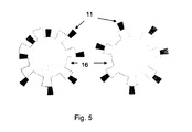
- eine schematische Darstellung des möglichen Einflusses einer ungleichen und einer gleichen Anzahl von Nuten und Federarmen.
- Die Abbildung gemäß
Fig. 1 zeigt ein Sicherungselement für Verdrehsicherung in perspektivischer Darstellung. Bei dem Element ist eine Reihe elastischer Arme 1, im Fall des hier dargestellten Ausführungsbeispiels acht, kreisförmig und äquidistant angeordnet, wobei die Arme 1 mit jeweils einem Ende an einem ringförmigen Teil 2 gehaltert sind. - Nach dem Einbau in ein entsprechendes Bauteil 3 greifen, wie in
Fig. 2 dargestellt, die elastischen Arme 1 um einen im Fall des hier dargestellten Ausführungsbeispiels sechseckigen Kopf 4 einer gegen ein mögliches Verdrehen zu sichernden Schraube 5. Das Verdrehen der Schraube 5 ist dadurch nur noch um wenige Winkelgrad und nur so lange möglich, bis die Kanten des Kopfes 4 der Schraube 5 an den Armen 1 zur Anlage gelangen und die entstehende axiale Kraft ein weiteres Verdrehen verhindert. Das Sicherungselement ist dabei mit dem Bauteil 3 verbunden, das als Widerlager für die auftretenden axialen Kräfte dient und das über die Schrauben 4 an einem zweiten Bauteil 7 gehaltert ist. -
Fig. 3 zeigt, wie die auf diese Weise in Funktion gebrachte Verdrehsicherung durch das Einsetzen eines herkömmlichen Schraubendrehwerkzeuges 6 in Form einer Werkzeug-Nuß entriegelt wird. Die Außenseite des Schraubendrehwerkzeuges 6 drückt dazu von innen her gegen die Arme 1 des Sicherungselementes und verformt diese so weit elastisch, daß sie den Schraubenkopf 4 freigeben. Die Schraube 5 kann nun mit Hilfe des Werkzeuges 6 frei herausgedreht werden. Soll sie erneut eingedreht und gegen Verdrehen gesichert werden, so biegt zunächst der Schraubenkopf 4 die elastischen Arme 1 bis zu ihrer Entsicherung vom Schraubenkopf 4 nach außen. Diese Stellung wird anschließend durch das Werkzeug 6 aufrecherhalten. Nach dem Entfernen des Werkzeuges 6 verriegeln die elastischen Arme 1 den Schraubenkopf 4 erneut, unabhängig von der Winkelstellung der Schraube 5 bzw. des Schraubenkopfes 4. Auf diese Weise wird eine bei einer unerwünschten Drehung der Schraube 5 entstehende axiale Bewegung der Schraube 5 zuverlässig verhindert und das Herausdrehen der Schraube 5 somit unterbunden. - Bei der in
Fig. 4 gezeigten zweiten Ausführungsform des Sicherungselementes rasten die elastischen Arme 11 in Nuten 16 eines Schraubenkopfes 14 ein und verhindern damit zuverlässig ein Verdrehen der Schraube. Es ist in dieser Ausführung allerdings vergleichsweise schwierig, die Arme einzurasten und gleichzeitig ein vorgegebenes Anzugsmoment auf die Schraube aufzubringen, da die genaue Position der Aussparungen bei der Fertigung des Gewindes nicht präzise genug festgelegt werden kann. Dieses Problem wird gemäß der inFig. 5 gezeigten bevorzugten Ausführungsform dadurch gelöst, daß die Anzahl der Nuten 16 um wenigstens eins geringer als die Anzahl der Arme 11 gewählt ist, wobei die Nuten 16 zusätzlich größer sind als die Breite der Arme 11. Auf diese Weise ist sichergestellt, daß immer zumindest ein Arm 11 in einer Nut 16 einrastet und ein Verdrehen der Schraube verhindert wird. - Bei dieser zweiten Ausführungsform ist es zudem insbesondere vorteilhaft, wenn die Arme 11 in radialer Richtung vergleichsweise dünn ausgebildet sind, um eine leichte Verformbarkeit durch das Schraubendrehwerkzeug zu erreichen. Zugleich sind vorzugsweise die Arme 11 in tangentialer Richtung vergleichsweise breit ausgebildet, um die auftretenden Torsionskräfte aufnehmen zu können. Weiterhin ist es in diesem Fall vorteilhaft, im zweiten Bauteil zusätzliche Führungen vorzusehen, die mit entsprechenden Auskragungen 17 des ringförmigen Teiles 12 korrespondieren und die auf die Arme 11 einwirkende Torsionskräfte aufnehmen können.
Claims (8)
- Verdrehsicherung für Schrauben für eine Verwendung unter Weltraumbedingungen, wobei die Schrauben zur Befestigung eines ersten Bauteiles an einem zweiten Bauteil vorgesehen sind und bei der Sicherungselemente die Schrauben beaufschlagen, dadurch gekennzeichnet, daß die Sicherungselemente als elastisch verschwenkbare Arme (1, 11) ausgebildet und kreisförmig und äquidistant mit jeweils einem Ende an einem ringförmigen Teil (2, 12) gehaltert sind, das seinerseits mit einem ersten Bauteil (3) verbunden ist, welches mittels der Schrauben (5) an einem zweiten Bauteil (7) gehaltert ist, und mit ihrem jeweils anderen Ende am Kopf (4, 14) der Schraube (5) anliegen und mittels eines Außenmantels einer einsteckbaren Hülse eines Werkzeuges (6) zum Verdrehen der Schrauben (5) aus einer Halteposition entriegelbar sind.
- Verdrehsicherung nach Anspruch 1, dadurch gekennzeichnet, daß insgesamt acht Arme (1, 11) vorgesehen sind.
- Verdrehsicherung nach Anspruch 1 oder 2, dadurch gekennzeichnet, daß die Arme (1, 11) durch das Einführen eines Schraubendrehwerkzeuges (6) in das Innere des ringförmigen Teiles (2, 12) entriegelbar sind.
- Verdrehsicherung nach Anspruch 1, dadurch gekennzeichnet, daß die Arme (11) mit zugeordneten Nuten (16) des Schraubenkopfes (14) zusammenwirken.
- Verdrehsicherung nach Anspruch 4, dadurch gekennzeichnet, daß die Anzahl der Nuten (16) um wenigstens eins geringer als die Anzahl der Arme (11) gewählt ist.
- Verdrehsicherung nach Anspruch 5, dadurch gekennzeichnet, daß die Nuten (16) größer sind als die Breite der Arme (11).
- Verdrehsicherung nach Anspruch 5 oder 6, dadurch gekennzeichnet, daß über einen Teil ihrer Länge die Erstreckung der Arme (11) in radialer Richtung geringer ist als in tangentialer Richtung.
- Verdrehsicherung nach einem der Ansprüche 5 bis 7, dadurch gekennzeichnet, daß am ringförmigen Teil (12) Auskragungen (17) vorgesehen sind, die mit entsprechenden Führungen am zweiten Bauteil zusammenwirken.
Priority Applications (2)
| Application Number | Priority Date | Filing Date | Title |
|---|---|---|---|
| DE102010035297A DE102010035297A1 (de) | 2010-08-20 | 2010-08-20 | Verdrehsicherung für Schrauben |
| EP11005815.3A EP2420686B1 (de) | 2010-08-20 | 2011-07-15 | Verdrehsicherung für Schrauben |
Applications Claiming Priority (2)
| Application Number | Priority Date | Filing Date | Title |
|---|---|---|---|
| DE102010035297A DE102010035297A1 (de) | 2010-08-20 | 2010-08-20 | Verdrehsicherung für Schrauben |
| EP11005815.3A EP2420686B1 (de) | 2010-08-20 | 2011-07-15 | Verdrehsicherung für Schrauben |
Publications (2)
| Publication Number | Publication Date |
|---|---|
| EP2420686A1 true EP2420686A1 (de) | 2012-02-22 |
| EP2420686B1 EP2420686B1 (de) | 2017-03-01 |
Family
ID=44840498
Family Applications (1)
| Application Number | Title | Priority Date | Filing Date |
|---|---|---|---|
| EP11005815.3A Not-in-force EP2420686B1 (de) | 2010-08-20 | 2011-07-15 | Verdrehsicherung für Schrauben |
Country Status (2)
| Country | Link |
|---|---|
| EP (1) | EP2420686B1 (de) |
| DE (1) | DE102010035297A1 (de) |
Cited By (2)
| Publication number | Priority date | Publication date | Assignee | Title |
|---|---|---|---|---|
| CN105667841A (zh) * | 2016-01-29 | 2016-06-15 | 中国人民解放军国防科学技术大学 | 六边形绳网收纳封装方法 |
| CN113291495A (zh) * | 2021-06-25 | 2021-08-24 | 安徽应流集团霍山铸造有限公司 | 一种基于柔性带收放与刚柔转换机构的空间机械臂 |
Families Citing this family (2)
| Publication number | Priority date | Publication date | Assignee | Title |
|---|---|---|---|---|
| DE102018105227A1 (de) * | 2018-03-07 | 2019-09-12 | Heiko Durst | Sicherungsanordnung zur Positionssicherung eines lösbaren Verbindungsmittels |
| DE202022104794U1 (de) | 2022-08-25 | 2023-11-28 | Marelli Automotive Lighting Reutlingen (Germany) GmbH | Einstellelement zur Einstellung eines Lichtmoduls |
Citations (4)
| Publication number | Priority date | Publication date | Assignee | Title |
|---|---|---|---|---|
| DD23834A (de) | ||||
| GB581213A (en) * | 1944-05-25 | 1946-10-04 | Bernard Claude Rowing | A locking clip for adapted nuts |
| DE3233976C1 (de) * | 1982-09-14 | 1983-08-25 | Daimler-Benz Ag, 7000 Stuttgart | Verdrehsicherung für Schrauben |
| EP0811776A2 (de) * | 1996-06-07 | 1997-12-10 | MAICO ELEKTROAPPARATE-FABRIK GmbH | Schraubensicherung |
-
2010
- 2010-08-20 DE DE102010035297A patent/DE102010035297A1/de not_active Withdrawn
-
2011
- 2011-07-15 EP EP11005815.3A patent/EP2420686B1/de not_active Not-in-force
Patent Citations (4)
| Publication number | Priority date | Publication date | Assignee | Title |
|---|---|---|---|---|
| DD23834A (de) | ||||
| GB581213A (en) * | 1944-05-25 | 1946-10-04 | Bernard Claude Rowing | A locking clip for adapted nuts |
| DE3233976C1 (de) * | 1982-09-14 | 1983-08-25 | Daimler-Benz Ag, 7000 Stuttgart | Verdrehsicherung für Schrauben |
| EP0811776A2 (de) * | 1996-06-07 | 1997-12-10 | MAICO ELEKTROAPPARATE-FABRIK GmbH | Schraubensicherung |
Cited By (2)
| Publication number | Priority date | Publication date | Assignee | Title |
|---|---|---|---|---|
| CN105667841A (zh) * | 2016-01-29 | 2016-06-15 | 中国人民解放军国防科学技术大学 | 六边形绳网收纳封装方法 |
| CN113291495A (zh) * | 2021-06-25 | 2021-08-24 | 安徽应流集团霍山铸造有限公司 | 一种基于柔性带收放与刚柔转换机构的空间机械臂 |
Also Published As
| Publication number | Publication date |
|---|---|
| EP2420686B1 (de) | 2017-03-01 |
| DE102010035297A1 (de) | 2012-02-23 |
Similar Documents
| Publication | Publication Date | Title |
|---|---|---|
| DE112007000086B4 (de) | Verbindungsanordnung mit einem Verbindungselement | |
| EP2378158B1 (de) | Spannvorrichtung für Ketten | |
| EP3714174B1 (de) | Drahtgewindeeinsatz | |
| EP3356697B1 (de) | Bauteil der hebe-, zurr- oder anschlagtechnik, insbesondere schäkel, für outdoor- oder offshore-anwendungen | |
| DE102015122385A1 (de) | Nockenbolzen und werkzeug-kupplungssystem für solche | |
| DE202012009468U1 (de) | Verschlussbolzen und Verschlusselement hiermit | |
| EP2420686B1 (de) | Verdrehsicherung für Schrauben | |
| EP3721102B1 (de) | Zweiteilige schraubenmutter mit hoher andrückkraft | |
| DE102009051540A1 (de) | Selbstsichernde Einstelleinrichtung, Fahrzeuglenkung und Verfahren zum Einstellen eines Spiels eines Druckstück in einer Fahrzeuglenkung | |
| DE1119604B (de) | Schraubensicherung | |
| DE102009033948A1 (de) | Kabel- oder Schlauchverschraubung | |
| EP3227041B1 (de) | Spannfutter | |
| EP2064454B1 (de) | Befestigungseinrichtung | |
| DE102019102768B4 (de) | Drehverschluss | |
| DE19610213C2 (de) | Spannfutter mit Bogenstück | |
| EP3153823A2 (de) | Befestigungseinheit | |
| DE2142488A1 (de) | Lösbarer Schraubverbinddr, insbesondere zum Anschluß von Tafeln an Rahmen od. dgl | |
| EP3115625B1 (de) | Zug-druck-stange mit verbindungsbolzen | |
| DE102013002443A1 (de) | Zentralverschlusselement für die Befestigung eines Bauteils auf einem Träger | |
| DE202011102773U1 (de) | Sicherungseinheit | |
| AT502399B1 (de) | Einrichtung zum festlegen eines tür- oder fenstergriffes | |
| EP3137260B1 (de) | Spannbolzen und spannvorrichtung mit einem solchen spannbolzen | |
| EP4226055B1 (de) | Vorrichtung zur befestigung an einem bauteil | |
| DE102004051669B4 (de) | Selbstsichernde Schraube und selbstsichernde Befestigungsanordnung | |
| DE29912708U1 (de) | Schraubwerkzeug zum Eindrehen von Gewindebolzen |
Legal Events
| Date | Code | Title | Description |
|---|---|---|---|
| AK | Designated contracting states |
Kind code of ref document: A1 Designated state(s): AL AT BE BG CH CY CZ DE DK EE ES FI FR GB GR HR HU IE IS IT LI LT LU LV MC MK MT NL NO PL PT RO RS SE SI SK SM TR |
|
| AX | Request for extension of the european patent |
Extension state: BA ME |
|
| PUAI | Public reference made under article 153(3) epc to a published international application that has entered the european phase |
Free format text: ORIGINAL CODE: 0009012 |
|
| 17P | Request for examination filed |
Effective date: 20120222 |
|
| 17Q | First examination report despatched |
Effective date: 20160624 |
|
| GRAP | Despatch of communication of intention to grant a patent |
Free format text: ORIGINAL CODE: EPIDOSNIGR1 |
|
| STAA | Information on the status of an ep patent application or granted ep patent |
Free format text: STATUS: GRANT OF PATENT IS INTENDED |
|
| INTG | Intention to grant announced |
Effective date: 20161129 |
|
| GRAS | Grant fee paid |
Free format text: ORIGINAL CODE: EPIDOSNIGR3 |
|
| GRAA | (expected) grant |
Free format text: ORIGINAL CODE: 0009210 |
|
| STAA | Information on the status of an ep patent application or granted ep patent |
Free format text: STATUS: THE PATENT HAS BEEN GRANTED |
|
| AK | Designated contracting states |
Kind code of ref document: B1 Designated state(s): AL AT BE BG CH CY CZ DE DK EE ES FI FR GB GR HR HU IE IS IT LI LT LU LV MC MK MT NL NO PL PT RO RS SE SI SK SM TR |
|
| REG | Reference to a national code |
Ref country code: GB Ref legal event code: FG4D Free format text: NOT ENGLISH |
|
| REG | Reference to a national code |
Ref country code: CH Ref legal event code: EP Ref country code: AT Ref legal event code: REF Ref document number: 871733 Country of ref document: AT Kind code of ref document: T Effective date: 20170315 |
|
| REG | Reference to a national code |
Ref country code: IE Ref legal event code: FG4D Free format text: LANGUAGE OF EP DOCUMENT: GERMAN |
|
| REG | Reference to a national code |
Ref country code: DE Ref legal event code: R096 Ref document number: 502011011694 Country of ref document: DE |
|
| REG | Reference to a national code |
Ref country code: SE Ref legal event code: TRGR |
|
| REG | Reference to a national code |
Ref country code: NL Ref legal event code: MP Effective date: 20170301 |
|
| REG | Reference to a national code |
Ref country code: LT Ref legal event code: MG4D |
|
| REG | Reference to a national code |
Ref country code: FR Ref legal event code: PLFP Year of fee payment: 7 |
|
| PG25 | Lapsed in a contracting state [announced via postgrant information from national office to epo] |
Ref country code: LT Free format text: LAPSE BECAUSE OF FAILURE TO SUBMIT A TRANSLATION OF THE DESCRIPTION OR TO PAY THE FEE WITHIN THE PRESCRIBED TIME-LIMIT Effective date: 20170301 Ref country code: FI Free format text: LAPSE BECAUSE OF FAILURE TO SUBMIT A TRANSLATION OF THE DESCRIPTION OR TO PAY THE FEE WITHIN THE PRESCRIBED TIME-LIMIT Effective date: 20170301 Ref country code: HR Free format text: LAPSE BECAUSE OF FAILURE TO SUBMIT A TRANSLATION OF THE DESCRIPTION OR TO PAY THE FEE WITHIN THE PRESCRIBED TIME-LIMIT Effective date: 20170301 Ref country code: GR Free format text: LAPSE BECAUSE OF FAILURE TO SUBMIT A TRANSLATION OF THE DESCRIPTION OR TO PAY THE FEE WITHIN THE PRESCRIBED TIME-LIMIT Effective date: 20170602 Ref country code: NO Free format text: LAPSE BECAUSE OF FAILURE TO SUBMIT A TRANSLATION OF THE DESCRIPTION OR TO PAY THE FEE WITHIN THE PRESCRIBED TIME-LIMIT Effective date: 20170601 |
|
| PG25 | Lapsed in a contracting state [announced via postgrant information from national office to epo] |
Ref country code: BG Free format text: LAPSE BECAUSE OF FAILURE TO SUBMIT A TRANSLATION OF THE DESCRIPTION OR TO PAY THE FEE WITHIN THE PRESCRIBED TIME-LIMIT Effective date: 20170601 Ref country code: RS Free format text: LAPSE BECAUSE OF FAILURE TO SUBMIT A TRANSLATION OF THE DESCRIPTION OR TO PAY THE FEE WITHIN THE PRESCRIBED TIME-LIMIT Effective date: 20170301 Ref country code: LV Free format text: LAPSE BECAUSE OF FAILURE TO SUBMIT A TRANSLATION OF THE DESCRIPTION OR TO PAY THE FEE WITHIN THE PRESCRIBED TIME-LIMIT Effective date: 20170301 Ref country code: ES Free format text: LAPSE BECAUSE OF FAILURE TO SUBMIT A TRANSLATION OF THE DESCRIPTION OR TO PAY THE FEE WITHIN THE PRESCRIBED TIME-LIMIT Effective date: 20170301 |
|
| PG25 | Lapsed in a contracting state [announced via postgrant information from national office to epo] |
Ref country code: NL Free format text: LAPSE BECAUSE OF FAILURE TO SUBMIT A TRANSLATION OF THE DESCRIPTION OR TO PAY THE FEE WITHIN THE PRESCRIBED TIME-LIMIT Effective date: 20170301 |
|
| REG | Reference to a national code |
Ref country code: DE Ref legal event code: R082 Ref document number: 502011011694 Country of ref document: DE Representative=s name: ELBPATENT-MARSCHALL & PARTNER MBB, DE Ref country code: DE Ref legal event code: R081 Ref document number: 502011011694 Country of ref document: DE Owner name: AIRBUS DEFENCE AND SPACE GMBH, DE Free format text: FORMER OWNER: ASTRIUM GMBH, 82024 TAUFKIRCHEN, DE |
|
| PG25 | Lapsed in a contracting state [announced via postgrant information from national office to epo] |
Ref country code: CZ Free format text: LAPSE BECAUSE OF FAILURE TO SUBMIT A TRANSLATION OF THE DESCRIPTION OR TO PAY THE FEE WITHIN THE PRESCRIBED TIME-LIMIT Effective date: 20170301 Ref country code: SK Free format text: LAPSE BECAUSE OF FAILURE TO SUBMIT A TRANSLATION OF THE DESCRIPTION OR TO PAY THE FEE WITHIN THE PRESCRIBED TIME-LIMIT Effective date: 20170301 Ref country code: EE Free format text: LAPSE BECAUSE OF FAILURE TO SUBMIT A TRANSLATION OF THE DESCRIPTION OR TO PAY THE FEE WITHIN THE PRESCRIBED TIME-LIMIT Effective date: 20170301 Ref country code: RO Free format text: LAPSE BECAUSE OF FAILURE TO SUBMIT A TRANSLATION OF THE DESCRIPTION OR TO PAY THE FEE WITHIN THE PRESCRIBED TIME-LIMIT Effective date: 20170301 |
|
| PG25 | Lapsed in a contracting state [announced via postgrant information from national office to epo] |
Ref country code: PT Free format text: LAPSE BECAUSE OF FAILURE TO SUBMIT A TRANSLATION OF THE DESCRIPTION OR TO PAY THE FEE WITHIN THE PRESCRIBED TIME-LIMIT Effective date: 20170703 Ref country code: SM Free format text: LAPSE BECAUSE OF FAILURE TO SUBMIT A TRANSLATION OF THE DESCRIPTION OR TO PAY THE FEE WITHIN THE PRESCRIBED TIME-LIMIT Effective date: 20170301 Ref country code: IS Free format text: LAPSE BECAUSE OF FAILURE TO SUBMIT A TRANSLATION OF THE DESCRIPTION OR TO PAY THE FEE WITHIN THE PRESCRIBED TIME-LIMIT Effective date: 20170701 Ref country code: PL Free format text: LAPSE BECAUSE OF FAILURE TO SUBMIT A TRANSLATION OF THE DESCRIPTION OR TO PAY THE FEE WITHIN THE PRESCRIBED TIME-LIMIT Effective date: 20170301 |
|
| PGFP | Annual fee paid to national office [announced via postgrant information from national office to epo] |
Ref country code: SE Payment date: 20170724 Year of fee payment: 7 |
|
| REG | Reference to a national code |
Ref country code: DE Ref legal event code: R097 Ref document number: 502011011694 Country of ref document: DE |
|
| PLBE | No opposition filed within time limit |
Free format text: ORIGINAL CODE: 0009261 |
|
| STAA | Information on the status of an ep patent application or granted ep patent |
Free format text: STATUS: NO OPPOSITION FILED WITHIN TIME LIMIT |
|
| PG25 | Lapsed in a contracting state [announced via postgrant information from national office to epo] |
Ref country code: DK Free format text: LAPSE BECAUSE OF FAILURE TO SUBMIT A TRANSLATION OF THE DESCRIPTION OR TO PAY THE FEE WITHIN THE PRESCRIBED TIME-LIMIT Effective date: 20170301 |
|
| 26N | No opposition filed |
Effective date: 20171204 |
|
| PG25 | Lapsed in a contracting state [announced via postgrant information from national office to epo] |
Ref country code: SI Free format text: LAPSE BECAUSE OF FAILURE TO SUBMIT A TRANSLATION OF THE DESCRIPTION OR TO PAY THE FEE WITHIN THE PRESCRIBED TIME-LIMIT Effective date: 20170301 |
|
| REG | Reference to a national code |
Ref country code: CH Ref legal event code: PL |
|
| REG | Reference to a national code |
Ref country code: IE Ref legal event code: MM4A |
|
| PG25 | Lapsed in a contracting state [announced via postgrant information from national office to epo] |
Ref country code: LI Free format text: LAPSE BECAUSE OF NON-PAYMENT OF DUE FEES Effective date: 20170731 Ref country code: CH Free format text: LAPSE BECAUSE OF NON-PAYMENT OF DUE FEES Effective date: 20170731 Ref country code: IE Free format text: LAPSE BECAUSE OF NON-PAYMENT OF DUE FEES Effective date: 20170715 |
|
| REG | Reference to a national code |
Ref country code: GB Ref legal event code: 732E Free format text: REGISTERED BETWEEN 20180405 AND 20180411 |
|
| REG | Reference to a national code |
Ref country code: BE Ref legal event code: MM Effective date: 20170731 |
|
| PG25 | Lapsed in a contracting state [announced via postgrant information from national office to epo] |
Ref country code: LU Free format text: LAPSE BECAUSE OF NON-PAYMENT OF DUE FEES Effective date: 20170715 |
|
| REG | Reference to a national code |
Ref country code: FR Ref legal event code: PLFP Year of fee payment: 8 |
|
| REG | Reference to a national code |
Ref country code: FR Ref legal event code: CD Owner name: AIRBUS DS GMBH, DE Effective date: 20180718 |
|
| PG25 | Lapsed in a contracting state [announced via postgrant information from national office to epo] |
Ref country code: BE Free format text: LAPSE BECAUSE OF NON-PAYMENT OF DUE FEES Effective date: 20170731 |
|
| REG | Reference to a national code |
Ref country code: AT Ref legal event code: MM01 Ref document number: 871733 Country of ref document: AT Kind code of ref document: T Effective date: 20170715 |
|
| PG25 | Lapsed in a contracting state [announced via postgrant information from national office to epo] |
Ref country code: MT Free format text: LAPSE BECAUSE OF FAILURE TO SUBMIT A TRANSLATION OF THE DESCRIPTION OR TO PAY THE FEE WITHIN THE PRESCRIBED TIME-LIMIT Effective date: 20170301 |
|
| PG25 | Lapsed in a contracting state [announced via postgrant information from national office to epo] |
Ref country code: AT Free format text: LAPSE BECAUSE OF NON-PAYMENT OF DUE FEES Effective date: 20170715 |
|
| PG25 | Lapsed in a contracting state [announced via postgrant information from national office to epo] |
Ref country code: SE Free format text: LAPSE BECAUSE OF NON-PAYMENT OF DUE FEES Effective date: 20180716 |
|
| PG25 | Lapsed in a contracting state [announced via postgrant information from national office to epo] |
Ref country code: MC Free format text: LAPSE BECAUSE OF FAILURE TO SUBMIT A TRANSLATION OF THE DESCRIPTION OR TO PAY THE FEE WITHIN THE PRESCRIBED TIME-LIMIT Effective date: 20170301 Ref country code: HU Free format text: LAPSE BECAUSE OF FAILURE TO SUBMIT A TRANSLATION OF THE DESCRIPTION OR TO PAY THE FEE WITHIN THE PRESCRIBED TIME-LIMIT; INVALID AB INITIO Effective date: 20110715 |
|
| PG25 | Lapsed in a contracting state [announced via postgrant information from national office to epo] |
Ref country code: CY Free format text: LAPSE BECAUSE OF NON-PAYMENT OF DUE FEES Effective date: 20170301 |
|
| PG25 | Lapsed in a contracting state [announced via postgrant information from national office to epo] |
Ref country code: MK Free format text: LAPSE BECAUSE OF FAILURE TO SUBMIT A TRANSLATION OF THE DESCRIPTION OR TO PAY THE FEE WITHIN THE PRESCRIBED TIME-LIMIT Effective date: 20170301 |
|
| PG25 | Lapsed in a contracting state [announced via postgrant information from national office to epo] |
Ref country code: TR Free format text: LAPSE BECAUSE OF FAILURE TO SUBMIT A TRANSLATION OF THE DESCRIPTION OR TO PAY THE FEE WITHIN THE PRESCRIBED TIME-LIMIT Effective date: 20170301 |
|
| PG25 | Lapsed in a contracting state [announced via postgrant information from national office to epo] |
Ref country code: AL Free format text: LAPSE BECAUSE OF FAILURE TO SUBMIT A TRANSLATION OF THE DESCRIPTION OR TO PAY THE FEE WITHIN THE PRESCRIBED TIME-LIMIT Effective date: 20170301 |
|
| PGFP | Annual fee paid to national office [announced via postgrant information from national office to epo] |
Ref country code: FR Payment date: 20200723 Year of fee payment: 10 Ref country code: GB Payment date: 20200727 Year of fee payment: 10 Ref country code: DE Payment date: 20200721 Year of fee payment: 10 |
|
| PGFP | Annual fee paid to national office [announced via postgrant information from national office to epo] |
Ref country code: IT Payment date: 20200724 Year of fee payment: 10 |
|
| REG | Reference to a national code |
Ref country code: DE Ref legal event code: R119 Ref document number: 502011011694 Country of ref document: DE |
|
| GBPC | Gb: european patent ceased through non-payment of renewal fee |
Effective date: 20210715 |
|
| PG25 | Lapsed in a contracting state [announced via postgrant information from national office to epo] |
Ref country code: GB Free format text: LAPSE BECAUSE OF NON-PAYMENT OF DUE FEES Effective date: 20210715 Ref country code: DE Free format text: LAPSE BECAUSE OF NON-PAYMENT OF DUE FEES Effective date: 20220201 |
|
| PG25 | Lapsed in a contracting state [announced via postgrant information from national office to epo] |
Ref country code: FR Free format text: LAPSE BECAUSE OF NON-PAYMENT OF DUE FEES Effective date: 20210731 |
|
| PG25 | Lapsed in a contracting state [announced via postgrant information from national office to epo] |
Ref country code: IT Free format text: LAPSE BECAUSE OF NON-PAYMENT OF DUE FEES Effective date: 20210715 |