EP2420597A1 - Lid for fused quartz crucible, fused quartz crucible and method for handling same - Google Patents
Lid for fused quartz crucible, fused quartz crucible and method for handling same Download PDFInfo
- Publication number
- EP2420597A1 EP2420597A1 EP10783140A EP10783140A EP2420597A1 EP 2420597 A1 EP2420597 A1 EP 2420597A1 EP 10783140 A EP10783140 A EP 10783140A EP 10783140 A EP10783140 A EP 10783140A EP 2420597 A1 EP2420597 A1 EP 2420597A1
- Authority
- EP
- European Patent Office
- Prior art keywords
- cover
- crucible
- vitreous silica
- opening portion
- silica crucible
- Prior art date
- Legal status (The legal status is an assumption and is not a legal conclusion. Google has not performed a legal analysis and makes no representation as to the accuracy of the status listed.)
- Withdrawn
Links
- VYPSYNLAJGMNEJ-UHFFFAOYSA-N Silicium dioxide Chemical compound O=[Si]=O VYPSYNLAJGMNEJ-UHFFFAOYSA-N 0.000 title claims abstract description 55
- 238000000034 method Methods 0.000 title claims abstract description 5
- 239000005350 fused silica glass Substances 0.000 title 2
- 230000002093 peripheral effect Effects 0.000 claims abstract description 14
- 239000000853 adhesive Substances 0.000 claims description 26
- 230000001070 adhesive effect Effects 0.000 claims description 26
- 238000004519 manufacturing process Methods 0.000 claims description 16
- 229910021420 polycrystalline silicon Inorganic materials 0.000 claims description 14
- 229910021421 monocrystalline silicon Inorganic materials 0.000 claims description 11
- 229910052751 metal Inorganic materials 0.000 claims description 6
- 238000002844 melting Methods 0.000 claims description 5
- 230000008018 melting Effects 0.000 claims description 5
- 239000002184 metal Substances 0.000 claims description 3
- 239000000843 powder Substances 0.000 abstract description 21
- 230000009545 invasion Effects 0.000 abstract description 17
- 239000000126 substance Substances 0.000 abstract description 14
- 238000011109 contamination Methods 0.000 abstract description 13
- 239000007858 starting material Substances 0.000 abstract description 5
- 238000005299 abrasion Methods 0.000 description 12
- 238000010276 construction Methods 0.000 description 7
- 239000013078 crystal Substances 0.000 description 6
- 239000000463 material Substances 0.000 description 5
- 239000000377 silicon dioxide Substances 0.000 description 5
- 239000011324 bead Substances 0.000 description 4
- 230000003749 cleanliness Effects 0.000 description 4
- -1 polyethylene Polymers 0.000 description 4
- 238000007789 sealing Methods 0.000 description 4
- 238000005406 washing Methods 0.000 description 4
- 239000004698 Polyethylene Substances 0.000 description 3
- 239000004743 Polypropylene Substances 0.000 description 3
- 230000000149 penetrating effect Effects 0.000 description 3
- 229920000573 polyethylene Polymers 0.000 description 3
- 229920001155 polypropylene Polymers 0.000 description 3
- 238000012545 processing Methods 0.000 description 3
- 239000002210 silicon-based material Substances 0.000 description 3
- PPBRXRYQALVLMV-UHFFFAOYSA-N Styrene Chemical compound C=CC1=CC=CC=C1 PPBRXRYQALVLMV-UHFFFAOYSA-N 0.000 description 2
- NIXOWILDQLNWCW-UHFFFAOYSA-N acrylic acid group Chemical group C(C=C)(=O)O NIXOWILDQLNWCW-UHFFFAOYSA-N 0.000 description 2
- 239000012080 ambient air Substances 0.000 description 2
- 230000002542 deteriorative effect Effects 0.000 description 2
- 239000000428 dust Substances 0.000 description 2
- 229920001971 elastomer Polymers 0.000 description 2
- 238000001095 inductively coupled plasma mass spectrometry Methods 0.000 description 2
- 238000011835 investigation Methods 0.000 description 2
- 230000035515 penetration Effects 0.000 description 2
- 238000005728 strengthening Methods 0.000 description 2
- 239000012780 transparent material Substances 0.000 description 2
- 239000004925 Acrylic resin Substances 0.000 description 1
- 229920000178 Acrylic resin Polymers 0.000 description 1
- 244000043261 Hevea brasiliensis Species 0.000 description 1
- VEXZGXHMUGYJMC-UHFFFAOYSA-N Hydrochloric acid Chemical compound Cl VEXZGXHMUGYJMC-UHFFFAOYSA-N 0.000 description 1
- BZHJMEDXRYGGRV-UHFFFAOYSA-N Vinyl chloride Chemical compound ClC=C BZHJMEDXRYGGRV-UHFFFAOYSA-N 0.000 description 1
- 229920000122 acrylonitrile butadiene styrene Polymers 0.000 description 1
- 239000007864 aqueous solution Substances 0.000 description 1
- 229910052804 chromium Inorganic materials 0.000 description 1
- 229910052802 copper Inorganic materials 0.000 description 1
- 230000003247 decreasing effect Effects 0.000 description 1
- 239000002019 doping agent Substances 0.000 description 1
- 230000000694 effects Effects 0.000 description 1
- 239000000839 emulsion Substances 0.000 description 1
- 230000002708 enhancing effect Effects 0.000 description 1
- 239000011521 glass Substances 0.000 description 1
- 239000012535 impurity Substances 0.000 description 1
- 238000010348 incorporation Methods 0.000 description 1
- 238000007689 inspection Methods 0.000 description 1
- 229910052742 iron Inorganic materials 0.000 description 1
- 230000033001 locomotion Effects 0.000 description 1
- 229910052749 magnesium Inorganic materials 0.000 description 1
- 238000007726 management method Methods 0.000 description 1
- 229910052748 manganese Inorganic materials 0.000 description 1
- 229920003052 natural elastomer Polymers 0.000 description 1
- 229920001194 natural rubber Polymers 0.000 description 1
- 229910052759 nickel Inorganic materials 0.000 description 1
- 238000012856 packing Methods 0.000 description 1
- 239000004417 polycarbonate Substances 0.000 description 1
- 229920000515 polycarbonate Polymers 0.000 description 1
- 229920000642 polymer Polymers 0.000 description 1
- 239000002994 raw material Substances 0.000 description 1
- 239000004065 semiconductor Substances 0.000 description 1
- 229920002379 silicone rubber Polymers 0.000 description 1
- 239000000243 solution Substances 0.000 description 1
- 238000003860 storage Methods 0.000 description 1
- 229920001935 styrene-ethylene-butadiene-styrene Polymers 0.000 description 1
- 239000000758 substrate Substances 0.000 description 1
- 229920002803 thermoplastic polyurethane Polymers 0.000 description 1
- 229910052719 titanium Inorganic materials 0.000 description 1
- 229910021642 ultra pure water Inorganic materials 0.000 description 1
- 239000012498 ultrapure water Substances 0.000 description 1
- 230000000007 visual effect Effects 0.000 description 1
- 229910052725 zinc Inorganic materials 0.000 description 1
- 229910052726 zirconium Inorganic materials 0.000 description 1
Images




Classifications
-
- C—CHEMISTRY; METALLURGY
- C30—CRYSTAL GROWTH
- C30B—SINGLE-CRYSTAL GROWTH; UNIDIRECTIONAL SOLIDIFICATION OF EUTECTIC MATERIAL OR UNIDIRECTIONAL DEMIXING OF EUTECTOID MATERIAL; REFINING BY ZONE-MELTING OF MATERIAL; PRODUCTION OF A HOMOGENEOUS POLYCRYSTALLINE MATERIAL WITH DEFINED STRUCTURE; SINGLE CRYSTALS OR HOMOGENEOUS POLYCRYSTALLINE MATERIAL WITH DEFINED STRUCTURE; AFTER-TREATMENT OF SINGLE CRYSTALS OR A HOMOGENEOUS POLYCRYSTALLINE MATERIAL WITH DEFINED STRUCTURE; APPARATUS THEREFOR
- C30B15/00—Single-crystal growth by pulling from a melt, e.g. Czochralski method
- C30B15/10—Crucibles or containers for supporting the melt
-
- B—PERFORMING OPERATIONS; TRANSPORTING
- B65—CONVEYING; PACKING; STORING; HANDLING THIN OR FILAMENTARY MATERIAL
- B65D—CONTAINERS FOR STORAGE OR TRANSPORT OF ARTICLES OR MATERIALS, e.g. BAGS, BARRELS, BOTTLES, BOXES, CANS, CARTONS, CRATES, DRUMS, JARS, TANKS, HOPPERS, FORWARDING CONTAINERS; ACCESSORIES, CLOSURES, OR FITTINGS THEREFOR; PACKAGING ELEMENTS; PACKAGES
- B65D43/00—Lids or covers for rigid or semi-rigid containers
- B65D43/02—Removable lids or covers
-
- B—PERFORMING OPERATIONS; TRANSPORTING
- B65—CONVEYING; PACKING; STORING; HANDLING THIN OR FILAMENTARY MATERIAL
- B65D—CONTAINERS FOR STORAGE OR TRANSPORT OF ARTICLES OR MATERIALS, e.g. BAGS, BARRELS, BOTTLES, BOXES, CANS, CARTONS, CRATES, DRUMS, JARS, TANKS, HOPPERS, FORWARDING CONTAINERS; ACCESSORIES, CLOSURES, OR FITTINGS THEREFOR; PACKAGING ELEMENTS; PACKAGES
- B65D77/00—Packages formed by enclosing articles or materials in preformed containers, e.g. boxes, cartons, sacks or bags
- B65D77/10—Container closures formed after filling
- B65D77/20—Container closures formed after filling by applying separate lids or covers, i.e. flexible membrane or foil-like covers
-
- C—CHEMISTRY; METALLURGY
- C30—CRYSTAL GROWTH
- C30B—SINGLE-CRYSTAL GROWTH; UNIDIRECTIONAL SOLIDIFICATION OF EUTECTIC MATERIAL OR UNIDIRECTIONAL DEMIXING OF EUTECTOID MATERIAL; REFINING BY ZONE-MELTING OF MATERIAL; PRODUCTION OF A HOMOGENEOUS POLYCRYSTALLINE MATERIAL WITH DEFINED STRUCTURE; SINGLE CRYSTALS OR HOMOGENEOUS POLYCRYSTALLINE MATERIAL WITH DEFINED STRUCTURE; AFTER-TREATMENT OF SINGLE CRYSTALS OR A HOMOGENEOUS POLYCRYSTALLINE MATERIAL WITH DEFINED STRUCTURE; APPARATUS THEREFOR
- C30B29/00—Single crystals or homogeneous polycrystalline material with defined structure characterised by the material or by their shape
- C30B29/02—Elements
- C30B29/06—Silicon
Definitions
- This invention relates to a vitreous silica crucible, and more particularly to a vitreous silica crucible used in a pulling step for the production of single crystal silicon. Particularly, it provides a structure of avoiding invasion of foreign substances into an inner face of a fabricated vitreous silica crucible during storage and transportation of the crucible.
- vitreous silica crucibles used in the melting of polycrystalline silicon as a raw material are washed and inspected after the fabrication, and thereafter acceptable products are shipped by bagging or the like.
- vitreous silica crucibles used in the melting of polycrystalline silicon as a raw material are washed and inspected after the fabrication, and thereafter acceptable products are shipped by bagging or the like.
- the size of the vitreous silica crucible particularly tends to be gradually increased for enhancing the production efficiency of single crystal silicon.
- a large-diameter crucible is not easy in the handling, and is apt to be easily contaminated even in the operation such as inspection, bagging or the like after the fabrication of the crucible.
- Patent Document 1 proposes a apparatus of automatically wrapping a washed vitreous silica crucible at a clean state for the purpose of mechanically packing the vitreous silica crucible at a clean state after the washing thereof.
- an object of the invention to reliably avoid invasion of foreign substances into an inside of a vitreous silica crucible at low cost up to an actual use time of the crucible to thereby enable handling of the crucible with no contamination.
- a vitreous silica crucible having a disk-shaped cover at its opening portion, wherein a flange portion of the cover is fixed to an outer peripheral end of the opening portion into close contact therewith.
- the vitreous silica crucible According to the invention is reliably avoided invasion of raw powder for a vitreous silica crucible into the inner face of the crucible and hence invasion of foreign substances into the inside of the vitreous silica crucible, so that the vitreous silica crucible can be handled without contaminating the inner face thereof over a period of time from the shipping of the crucible to the melting step of polycrystalline silicon.
- FIG. 1(a) is shown a radial cross-section of a crucible before the mounting of a cover according to the invention
- FIG. 1(b) illustrates a radial cross-section of the crucible after the mounting of the cover.
- a reference symbol 1 is a vitreous silica crucible (hereinafter referred to as a crucible simply), and a cover 3 is mounted onto an opening portion 2 of the crucible 1.
- the cover 3 is a disk shape having a figure similar to the opening portion 2 and has a flange portion 4 closely contacting with an outer peripheral end 2a of the opening portion 2 of the crucible 1. That is, the cover 3 is attached to the opening portion 2 of the crucible 1 in a way that the flange portion 4 is brought into close contact with the outer peripheral end 2a. At this moment, it is preferable that a diameter of the flange portion 4 is equal to or slightly smaller than an outer diameter of the crucible 1 for covering the opening portion 2 without space.
- the cover 3 is made from a flexible material such as ABS resin, urethane resin, polyethylene, polypropylene, vinyl chloride, acrylic resin, polycarbonate or the like.
- the cover 3 as a whole or the flange portion 4 of the cover 3 is bent outward in a radial direction, which enables the flange portion 4 with the restoring force thereof to press against the outer peripheral end 2a as shown in FIG. 2(b) . This is preferable in view of reliably conducting the detaching of the cover.
- the cover 3 having such a construction When the cover 3 having such a construction is mounted onto the opening portion 2 of the crucible 1, the cover 3 is brought into close contact with the outer peripheral end 2a and the circumferential end face 2b of the opening portion 2 to close the opening portion 2 reliably, whereby there is obviated such a scene that the starting material powder or the like attached onto the crucible 1 is guided into the inside, for example, through wrapping, so that invasion of foreign substances into the inside of the crucible can be avoided reliably.
- an adhesive member 5 is disposed at the inside of the cover 3 and on an area contacting with the circumferential end face 2b of the opening portion 2. Because, when the cover 3 provided with the adhesive member 5 is used and attached to the opening potion 2 of the crucible 1, the closely contacting between the crucible 1 and the cover 3 is more enhanced and the sealing performance of the crucible 1 as a container is further improved, which is effective for preventing invasion of foreign substance such as moisture or the like penetrating from a space between the cover 3 and the crucible 1. Moreover, since the moisture included in ambient air may be blended with metal elements deteriorating the performances of the crucible, it is preferable to reduce the penetration of the moisture for maintaining the performance of the crucible.
- the inventors have found that when the cover 3 is attached to the crucible 1 without interposing the adhesive member 5 as shown in FIG. 1 , abrasion powder is generated by contacting the cover 3 with the circumferential end face 2b of the opening portion 2 of the crucible 1 and hence there is caused a possibility that the abrasion powder invades into the inside of the crucible 1 as foreign substances.
- the adhesive member 5 is interposed between the cover 3 and the crucible 1 as shown in FIG. 2 , abrasion powder is hardly generated, but also the generated abrasion powder is absorbed by the adhesive member 5, which makes it possible to suppress invasion of the abrasion powder into the crucible 1 more effectively.
- adhesive member used herein means an adhesive itself or an adhesive sheet formed by applying an adhesive onto any substrate, and it is desirable in terms of reliability of adhesion fixation, peeling simplicity and the like that the member is detachable to a target to be attached and a part of the member does not remain on the target even in the peeling after attachment.
- the adhesive member 5 is preferable to have an elasticity from a viewpoint of improving the closely adhesion between the crucible 1 and the cover 3.
- an elastic member at the inside of the cover 3 and on an area contacting with the circumferential end face 2b of the opening portion 2 although not shown. Because, when the cover 3 provided with the adhesive member 5 is used and attached to the opening potion 2 of the crucible 1, the closely contacting between the crucible 1 and the cover 3 is more enhanced and the sealing performance of the crucible 1 as a container is further improved, which is effective for preventing invasion of foreign substance such as moisture or the like penetrating from a space between the cover 3 and the crucible 1. Moreover, since the moisture included in ambient air may be blended with metal elements deteriorating the performances of the crucible, it is preferable to reduce the penetration of the moisture for maintaining the performance of the crucible.
- the generation of abrasion powder is suppressed likewise the adhesive member 5, and hence there is no possibility that abrasion powder invades into the inside of the crucible 1 as foreign substances.
- the elastic member is preferable to have an adhesion performance as mentioned above from a viewpoint of improving the closely adhesion between the crucible 1 and the cover 3.
- the adhesive member and the elastic member used in the invention are not particularly limited as long as the above properties are fulfilled, but include, for example, acrylic ones and rubber-based ones.
- acrylic member is used an emulsion type member
- rubber-based member are used natural rubber, styrene-based synthetic block polymers (for example, SIS, SBS, SEBS (hydrogenated type of SBS), SIPS (hydrogenated type of SIS), and so on).
- SIS styrene-based synthetic block polymers
- SBS synthetic block polymers
- SEBS hydrogenated type of SBS
- SIPS hydrogenated type of SIS
- the material of the adhesive member and the elastic member is silicon rubber being less in the influence of invasion.
- the flange portion 4 is bent toward the crucible at two stages so as to have a stepwise shape extending outward in a radial direction.
- a bent portion comprises a first bent section 4a located inward in the radial direction and a second bent section 4b located outward in the radial direction relative to the first bent section 4a.
- FIG. 3(b) when the cover 3 having such a construction is mounted onto the opening portion 2 of the crucible 1, the cover 3 is in close contact partially with the outer peripheral end 2a and the circumferential end face 2b of the opening portion 2, while the opening portion 2 is reliably closed and a contacting area of the cover 3 to the crucible 1 becomes small.
- the cover 3 shown in FIG. 3 is provided with the adhesive member 5 likewise the cover shown in FIG. 2 from a viewpoint of suppressing invasion of foreign substances into the crucible.
- a diameter of the flange portion 4 before attachment to the crucible 1 is equal to or smaller than an outer diameter of the crucible 1 for reliably covering the circumferential end face 2b to avoid contamination.
- FIG. 4 it is preferable to interpose a band-shaped adhesive member 6 between the crucible 1 and the outer peripheral end 2a of the cover 3 when the cover 3 is attached to the crucible 1.
- the band-shaped adhesive member 6 is attached onto the outer peripheral end 2a of the opening portion 2 of the crucible 1.
- the cover 3 having the adhesive member 6 shown in FIG. 4(b) , and then the cover 3 is attached to the crucible 1 so that the first bent section 4a is in contact with the circumferential end face 2b of the opening portion 2 and the second bent section 4b is in contact with the band-shaped adhesive member 6 as shown in FIG. 4(c) .
- the opening portion 2 is reliably closed to obviate such a scene that the starting material powder or the like attached onto the crucible 1 is guided into the inside, for example, through wrapping, so that invasion of foreign substances into the inside of the crucible can be avoided reliably. Also, by the attachment of the cover 3 interposed with the band-shaped adhesive member 6 is further improved the sealing performance of the crucible 1 as a container, which is effective for preventing invasion of foreign substance such as moisture or the like penetrating from a space between the cover 3 and the crucible 1.
- the cover 3 is protruded outward, whereby it is possible to secure a large space 3a in the crucible, which is advantageous when a mountain of polycrystalline silicon is charged in the production of single crystal silicon as described later.
- an upper face 8 of the cover 3 is transparent and lens-shaped, which is significantly effective to recognize a state inside the crucible 1 in detail during the production even when polycrystalline silicon, dopant and the like are charged into the crucible 1 and the cover 3 is attached to the crucible 1.
- the cover 3 shown in FIG. 7 is cup-shaped projecting outward, and an inner face thereof is provided with beads 9 for strengthening the cover 3.
- Such beads 9 are provided through bead processing (also referred to as beading processing). It should be noted that the cover 3 can be subjected to other processing for the purpose of strengthening the cover 3.
- an identifier such as a bar-code, a QR code or the like to the cover 3 because it is difficult to engrave a bar-code on a glass material constituting the crucible, and a single body of a crucible and another bar-code are used side by side as a lot identifier.
- a bar-code to the cover may be moved the single body of the crucible. By the way, when a bar-code seal is applied to the conventional wrapping sheet, the transportation as a single body is possible.
- the wrapping is peeled off for charging polycrystalline Si into the crucible, it is disadvantageous that the wrapping cannot be reused.
- an identifier capable of including electronic data such as an IC tag or the like, which is becoming common rapidly recently, is attached to the cover 3. Because, when the identifier capable of including electronic data such as an IC tag or the like is attached to the cover 3 and electrical signals are transmitted externally, electronic data can be written in the IC tag and it is possible to easily identify materials charged into the crucible based on such electronic data. In this way, the management of the crucible 1 becomes easier, and the handling of the desired crucible 1 becomes easier. Moreover, the identifier capable of including electronic data such as an IC tag or the like can be reused many times, which is preferable from a viewpoint of reducing the production cost.
- the cover 3 attached to the opening portion 2 of the crucible 1 is removed to use the crucible 1, for example, when the attached cover 3 is removed for charging polycrystalline Si into the crucible 1, it is preferable to invert the crucible 1 and direct the opening portion downward in a vertical direction so as to remove the cover 3.
- By directing the opening portion of the crucible 1 downward in the removal of the cover 3 can be avoided invasion of foreign substances attached to the surface of the cover 3 such as starting material powder, dust and the like.
- the cover can be used repeatedly by washing.
- the existing sheet is generally disposable because the washing is difficult.
- the cover since the cover is washable, it can be provided with higher cleanliness.
- the cleanliness of the cover it is preferable that the amount of metal components attached at least on the inner face of the cover is not more than 0.05 ng/cm 2 in order to enhance the cleanliness in the inner face of the crucible.
- the cleanliness of the cover can be measured by inductively-coupled plasma mass spectrometry (ICP-MS) after an aqueous solution of hydrogen chloride (HCL) is applied on a surface to be measured such as the inner face of the cover or the like and the applied solution is recovered.
- the metal elements to be measured are Na, K, Li, Al, Ca, Co, Cr, Cu, Fe, Mg, Mn, Ni, Ti, Zn, Zr, Ba, P and the like.
- the use of the aforementioned cover 3 enables the handling of the crucible as described below. That is, in the production of single crystal silicon as shown in FIG. 8 , from a crucible 1 shipped with a cover 3 as shown in FIG. 8(a) is first removed the cover 3 as shown in FIG. 8(b) , and polycrystalline silicon 10 is charged in the crucible 1 as shown in FIG. 8(c) , and immediately the cover 3 is mounted onto an opening portion 2 of the crucible 1 as shown in FIG. 8(d) . After this, the crucible 1 is stored in a state shown in FIG. 8(e) where the inside of the crucible 1 is blocked from the outside world by the attachment of the cover 3, whereby the starting silicon material in the crucible 1 can be kept free from contamination during waiting time until melting of polycrystalline silicon 10 is conducted.
- the cover 3 is rendered to be transparent as an observation window.
- the whole of the cover 3 can be made from a transparent material. If visual observation inside the crucible 1 is easy, it is convenient to distinguish a crucible charged with the starting silicon material from a crucible with no content.
- the transparent material is preferable polyethylene (PE), polypropylene (PP) or the like.
- the number of silica powder incorporated into the inner face of the crucible is determined by visually counting the number of silica powder and silica pieces attached on the inner face of the crucible before filling polycrystalline silicon and after the crucible is delivered to a pulling step for the production of single crystal silicon and the cover is removed.
- the unit of the number is "pieces”.
- the crystal yield indicates a ratio of crystal weight obtained as a single crystal to weight of the starting material.
- FIG. 4 Conventional wrap Neither wrap nor cover Number of silica powder incorporated into inner face of crucible (*) 5 4 1 0 10 100 Crystal yield (%) 81 81 83 83 80 70 (*) Measuring condition: Measured after the delivery to a pulling step for the production of single crystal silicon
Landscapes
- Chemical & Material Sciences (AREA)
- Engineering & Computer Science (AREA)
- Crystallography & Structural Chemistry (AREA)
- Materials Engineering (AREA)
- Metallurgy (AREA)
- Organic Chemistry (AREA)
- Mechanical Engineering (AREA)
- Crystals, And After-Treatments Of Crystals (AREA)
- Packages (AREA)
- Closures For Containers (AREA)
- Sampling And Sample Adjustment (AREA)
Abstract
Description
- This invention relates to a vitreous silica crucible, and more particularly to a vitreous silica crucible used in a pulling step for the production of single crystal silicon. Particularly, it provides a structure of avoiding invasion of foreign substances into an inner face of a fabricated vitreous silica crucible during storage and transportation of the crucible.
- In the production of single crystal silicon, it is general that vitreous silica crucibles used in the melting of polycrystalline silicon as a raw material are washed and inspected after the fabrication, and thereafter acceptable products are shipped by bagging or the like.
With the increase of purity in semiconductor materials, it is important to suppress various contaminations during the production of single crystal silicon, and hence it is desired to control the contamination even in the vitreous silica crucibles at minimum. That is, when the vitreous silica crucible is used for pulling a single crystal, it is paid careful attention to the contamination by washing the inside of the crucible with ultra-pure water or the like prior to use. For this end, it is first important to prevent contamination by dust or the like even in a period of time from the shipping to the use of the fabricated crucible.
Recently, the size of the vitreous silica crucible particularly tends to be gradually increased for enhancing the production efficiency of single crystal silicon. However, such a large-diameter crucible is not easy in the handling, and is apt to be easily contaminated even in the operation such as inspection, bagging or the like after the fabrication of the crucible. - In order to solve such a problem,
Patent Document 1 proposes a apparatus of automatically wrapping a washed vitreous silica crucible at a clean state for the purpose of mechanically packing the vitreous silica crucible at a clean state after the washing thereof. -
- Patent Document 1:
JP-A-2000-219207 - By wrapping with an apparatus described in
Patent Document 1, it is made possible to store the washed vitreous silica crucible at a clean state and particularly avoid contamination in the shipping. However, such wrapping requires an expensive apparatus and cannot be reused, so that the cost for preventing contamination inside the crucible has been enormous. Therefore, it is desired to provide a method for avoiding contamination inside the vitreous silica crucible at low cost. - It is, therefore, an object of the invention to reliably avoid invasion of foreign substances into an inside of a vitreous silica crucible at low cost up to an actual use time of the crucible to thereby enable handling of the crucible with no contamination.
- The summary and construction of the invention are as follows:
- (1) A cover for a vitreous silica crucible to be mounted onto an opening portion of a vitreous silica crucible, comprising a flange portion in close contact with an outer peripheral end of the opening portion.
- (2) A cover for a vitreous silica crucible according to the item (1), wherein an adhesive member is disposed on an area of the cover contacting with a circumferential end face of the opening portion.
- (3) A cover for a vitreous silica crucible according to the item (1), wherein an elastic member is disposed on an area of the cover contacting with a circumferential end face of the opening portion.
- (4) A cover for a vitreous silica crucible according to the item (1), (2) or (3), wherein an amount of metal components attached to at least an inner surface of the cover is not more than 0.05 ng/cm2.
- (5) A cover for a vitreous silica crucible according to any one of the items (1) to (4), wherein the cover has a flexibility.
- (6) A cover for a vitreous silica crucible according to any one of the items (1) to (5), wherein the cover has an identifier.
- (7) A cover for a vitreous silica crucible according to any one of the items (1) to (6), wherein at least a part of the cover is transparent.
- (8) A vitreous silica crucible having a disk-shaped cover at its opening portion, wherein a flange portion of the cover is fixed to an outer peripheral end of the opening portion into close contact therewith.
- (9) A method of handling a vitreous silica crucible, wherein a cover as disclosed in any one of the items (1) to (7) is mounted onto an opening portion of the vitreous silica crucible during waiting time until polycrystalline silicon is charged into the vitreous silica crucible to conduct melting of the polycrystalline silicon in the production of single crystal silicon.
- According to the invention is reliably avoided invasion of raw powder for a vitreous silica crucible into the inner face of the crucible and hence invasion of foreign substances into the inside of the vitreous silica crucible, so that the vitreous silica crucible can be handled without contaminating the inner face thereof over a period of time from the shipping of the crucible to the melting step of polycrystalline silicon.
-
-
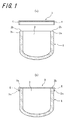
FIG. 1 is a radial cross-sectional view of a crucible illustrating a cover for a crucible according to the invention. -
FIG. 2 is a radial cross-sectional view of a crucible illustrating another cover for a crucible according to the invention. -
FIG. 3 is a radial cross-sectional view of a crucible illustrating another cover for a crucible according to the invention. -
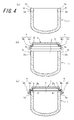
FIG. 4 is a radial cross-sectional view of a crucible illustrating another cover for a crucible according to the invention. -
FIG. 5 is a radial cross-sectional view of a crucible illustrating another cover for a crucible according to the invention. -
FIG. 6 is a radial cross-sectional view of a crucible illustrating another cover for a crucible according to the invention. -
FIG. 7 is a radial cross-sectional view of a crucible illustrating another cover for a crucible according to the invention. -
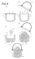
FIG. 8 is a flow chart illustrating handling of a crucible. - A vitreous silica crucible provided with a cover according to the invention will be described in detail with reference to the accompanying drawings. In
FIG. 1(a) is shown a radial cross-section of a crucible before the mounting of a cover according to the invention, andFIG. 1(b) illustrates a radial cross-section of the crucible after the mounting of the cover.
In this figure, areference symbol 1 is a vitreous silica crucible (hereinafter referred to as a crucible simply), and acover 3 is mounted onto anopening portion 2 of thecrucible 1. Thecover 3 is a disk shape having a figure similar to theopening portion 2 and has aflange portion 4 closely contacting with an outerperipheral end 2a of theopening portion 2 of thecrucible 1. That is, thecover 3 is attached to theopening portion 2 of thecrucible 1 in a way that theflange portion 4 is brought into close contact with the outerperipheral end 2a. At this moment, it is preferable that a diameter of theflange portion 4 is equal to or slightly smaller than an outer diameter of thecrucible 1 for covering theopening portion 2 without space. - Furthermore, the
cover 3 is made from a flexible material such as ABS resin, urethane resin, polyethylene, polypropylene, vinyl chloride, acrylic resin, polycarbonate or the like. In the mounting, thecover 3 as a whole or theflange portion 4 of thecover 3 is bent outward in a radial direction, which enables theflange portion 4 with the restoring force thereof to press against the outerperipheral end 2a as shown inFIG. 2(b) . This is preferable in view of reliably conducting the detaching of the cover. - When the
cover 3 having such a construction is mounted onto theopening portion 2 of thecrucible 1, thecover 3 is brought into close contact with the outerperipheral end 2a and thecircumferential end face 2b of theopening portion 2 to close theopening portion 2 reliably, whereby there is obviated such a scene that the starting material powder or the like attached onto thecrucible 1 is guided into the inside, for example, through wrapping, so that invasion of foreign substances into the inside of the crucible can be avoided reliably. - As shown in
FIG. 2 , it is preferable that anadhesive member 5 is disposed at the inside of thecover 3 and on an area contacting with thecircumferential end face 2b of theopening portion 2. Because, when thecover 3 provided with theadhesive member 5 is used and attached to theopening potion 2 of thecrucible 1, the closely contacting between thecrucible 1 and thecover 3 is more enhanced and the sealing performance of thecrucible 1 as a container is further improved, which is effective for preventing invasion of foreign substance such as moisture or the like penetrating from a space between thecover 3 and thecrucible 1. Moreover, since the moisture included in ambient air may be blended with metal elements deteriorating the performances of the crucible, it is preferable to reduce the penetration of the moisture for maintaining the performance of the crucible. The inventors have found that when thecover 3 is attached to thecrucible 1 without interposing theadhesive member 5 as shown inFIG. 1 , abrasion powder is generated by contacting thecover 3 with thecircumferential end face 2b of theopening portion 2 of thecrucible 1 and hence there is caused a possibility that the abrasion powder invades into the inside of thecrucible 1 as foreign substances. However, when theadhesive member 5 is interposed between thecover 3 and thecrucible 1 as shown inFIG. 2 , abrasion powder is hardly generated, but also the generated abrasion powder is absorbed by theadhesive member 5, which makes it possible to suppress invasion of the abrasion powder into thecrucible 1 more effectively. The term "adhesive member" used herein means an adhesive itself or an adhesive sheet formed by applying an adhesive onto any substrate, and it is desirable in terms of reliability of adhesion fixation, peeling simplicity and the like that the member is detachable to a target to be attached and a part of the member does not remain on the target even in the peeling after attachment. Moreover, theadhesive member 5 is preferable to have an elasticity from a viewpoint of improving the closely adhesion between thecrucible 1 and thecover 3. - Alternatively, it is preferable to dispose an elastic member at the inside of the
cover 3 and on an area contacting with thecircumferential end face 2b of theopening portion 2 although not shown. Because, when thecover 3 provided with theadhesive member 5 is used and attached to theopening potion 2 of thecrucible 1, the closely contacting between thecrucible 1 and thecover 3 is more enhanced and the sealing performance of thecrucible 1 as a container is further improved, which is effective for preventing invasion of foreign substance such as moisture or the like penetrating from a space between thecover 3 and thecrucible 1. Moreover, since the moisture included in ambient air may be blended with metal elements deteriorating the performances of the crucible, it is preferable to reduce the penetration of the moisture for maintaining the performance of the crucible. Also, the generation of abrasion powder is suppressed likewise theadhesive member 5, and hence there is no possibility that abrasion powder invades into the inside of thecrucible 1 as foreign substances. Furthermore, the elastic member is preferable to have an adhesion performance as mentioned above from a viewpoint of improving the closely adhesion between thecrucible 1 and thecover 3. - The adhesive member and the elastic member used in the invention are not particularly limited as long as the above properties are fulfilled, but include, for example, acrylic ones and rubber-based ones. As the acrylic member is used an emulsion type member, and as the rubber-based member are used natural rubber, styrene-based synthetic block polymers (for example, SIS, SBS, SEBS (hydrogenated type of SBS), SIPS (hydrogenated type of SIS), and so on). Here, assuming that abrasion powder generated by contact between the
cover 3 and theopening portion 2 of thecrucible 1 invades into the inside of the crucible, it is preferable that the material of the adhesive member and the elastic member is silicon rubber being less in the influence of invasion. - Furthermore, as shown in
FIG. 3 , it is possible that theflange portion 4 is bent toward the crucible at two stages so as to have a stepwise shape extending outward in a radial direction. Such a bent portion comprises a firstbent section 4a located inward in the radial direction and a secondbent section 4b located outward in the radial direction relative to the firstbent section 4a. As shown inFIG. 3(b) , when thecover 3 having such a construction is mounted onto theopening portion 2 of thecrucible 1, thecover 3 is in close contact partially with the outerperipheral end 2a and thecircumferential end face 2b of theopening portion 2, while theopening portion 2 is reliably closed and a contacting area of thecover 3 to thecrucible 1 becomes small. Thus, even if thecover 3 is moved relative to thecrucible 1 by vibration during transportation or the like and thecrucible 1 and/or thecover 3 are worn by friction therebetween to generate abrasion powder, since the contacting area between thecover 3 and thecrucible 1 is small, the amount of abrasion powder generated in proportion to the contacting area is decreased and hence it is made possible to avoid invasion of foreign substances into the crucible more effectively. Even in this case, when thecover 3 is mounted, thecover 3 as a whole or theflange portion 4 of thecover 3 is bent outward in a radial direction likewise the case shown inFIG. 1 , which enables theflange portion 4 with the restoring force thereof to press against the outerperipheral end 2a as shown inFIG. 3(b) , which is preferable in view of reliably conducting the detaching of the cover. Moreover, thecover 3 shown inFIG. 3 is provided with theadhesive member 5 likewise the cover shown inFIG. 2 from a viewpoint of suppressing invasion of foreign substances into the crucible. - According to the construction of the cover shown in
FIG. 3 , since thecircumferential end face 2b of theopening portion 2 is covered with theflange portion 4, contamination to thecircumferential end face 2b can be also avoided, which is particularly effective for avoiding incorporation of impurities in the pulling step for the production of single crystal silicon. In this case, it is preferable that a diameter of theflange portion 4 before attachment to thecrucible 1 is equal to or smaller than an outer diameter of thecrucible 1 for reliably covering thecircumferential end face 2b to avoid contamination. - Furthermore, as shown in
FIG. 4 , it is preferable to interpose a band-shapedadhesive member 6 between thecrucible 1 and the outerperipheral end 2a of thecover 3 when thecover 3 is attached to thecrucible 1. First, as shown inFIG. 4(a) , the band-shapedadhesive member 6 is attached onto the outerperipheral end 2a of theopening portion 2 of thecrucible 1. Next, there is provided thecover 3 having theadhesive member 6 shown inFIG. 4(b) , and then thecover 3 is attached to thecrucible 1 so that the firstbent section 4a is in contact with thecircumferential end face 2b of theopening portion 2 and the secondbent section 4b is in contact with the band-shapedadhesive member 6 as shown inFIG. 4(c) . When thecover 3 having such a construction is mounted onto theopening portion 2 of thecrucible 1, theopening portion 2 is reliably closed to obviate such a scene that the starting material powder or the like attached onto thecrucible 1 is guided into the inside, for example, through wrapping, so that invasion of foreign substances into the inside of the crucible can be avoided reliably. Also, by the attachment of thecover 3 interposed with the band-shapedadhesive member 6 is further improved the sealing performance of thecrucible 1 as a container, which is effective for preventing invasion of foreign substance such as moisture or the like penetrating from a space between thecover 3 and thecrucible 1. Furthermore, since thecover 3 is attached via theadhesive member 6, frictional force between thecover 3 and thecrucible 1 is improved to make the attachment of thecover 3 more stable. Therefore, contamination of thecrucible 1 resulted from the cover coming off due to vibrations during transportation, and movement of thecover 3 relative to thecrucible 1 are suppressed to prevent the generation of abrasion powder resulted therefrom, so that it is possible to avoid invasion of such abrasion powder into thecrucible 1.
Moreover, as shown inFIGS. 5(a) to 5(c) , it is possible to take such a construction that thecover 3 is attached to thecrucible 1 with the band-shapedadhesive member 6 interposed between thecrucible 1 and thecover 3 and thereafter a cup-shapedelastic member 7 is mounted onto thecrucible 1 along the outer face of thecrucible 1 to lock an end portion of the cup-shapedelastic member 7 to the secondbent section 4b of theflange portion 4 of thecover 3. By adopting such a construction is further improved the sealing performance of thecrucible 1 as a container but also the attachment of thecover 3 is made more stable, and thecover 3 hardly comes off due to vibrations or the like. - Furthermore, as shown in
FIGS. 6 and7 , thecover 3 is protruded outward, whereby it is possible to secure alarge space 3a in the crucible, which is advantageous when a mountain of polycrystalline silicon is charged in the production of single crystal silicon as described later. In thecover 3 shown inFIG. 6 , anupper face 8 of thecover 3 is transparent and lens-shaped, which is significantly effective to recognize a state inside thecrucible 1 in detail during the production even when polycrystalline silicon, dopant and the like are charged into thecrucible 1 and thecover 3 is attached to thecrucible 1. On the other hand, thecover 3 shown inFIG. 7 is cup-shaped projecting outward, and an inner face thereof is provided with beads 9 for strengthening thecover 3. Such beads 9 are provided through bead processing (also referred to as beading processing). It should be noted that thecover 3 can be subjected to other processing for the purpose of strengthening thecover 3. - In addition, it is preferable to provide an identifier such as a bar-code, a QR code or the like to the
cover 3 because it is difficult to engrave a bar-code on a glass material constituting the crucible, and a single body of a crucible and another bar-code are used side by side as a lot identifier. However, by applying a bar-code to the cover may be moved the single body of the crucible. By the way, when a bar-code seal is applied to the conventional wrapping sheet, the transportation as a single body is possible. However, once the wrapping is peeled off for charging polycrystalline Si into the crucible, it is disadvantageous that the wrapping cannot be reused.
Also, it is significantly effective in the production that an identifier capable of including electronic data such as an IC tag or the like, which is becoming common rapidly recently, is attached to thecover 3. Because, when the identifier capable of including electronic data such as an IC tag or the like is attached to thecover 3 and electrical signals are transmitted externally, electronic data can be written in the IC tag and it is possible to easily identify materials charged into the crucible based on such electronic data. In this way, the management of thecrucible 1 becomes easier, and the handling of the desiredcrucible 1 becomes easier. Moreover, the identifier capable of including electronic data such as an IC tag or the like can be reused many times, which is preferable from a viewpoint of reducing the production cost. - When the
cover 3 attached to theopening portion 2 of thecrucible 1 is removed to use thecrucible 1, for example, when the attachedcover 3 is removed for charging polycrystalline Si into thecrucible 1, it is preferable to invert thecrucible 1 and direct the opening portion downward in a vertical direction so as to remove thecover 3. By directing the opening portion of thecrucible 1 downward in the removal of thecover 3 can be avoided invasion of foreign substances attached to the surface of thecover 3 such as starting material powder, dust and the like. - Also, the cover can be used repeatedly by washing. The existing sheet is generally disposable because the washing is difficult. Further, since the cover is washable, it can be provided with higher cleanliness. As the cleanliness of the cover, it is preferable that the amount of metal components attached at least on the inner face of the cover is not more than 0.05 ng/cm2 in order to enhance the cleanliness in the inner face of the crucible.
Moreover, the cleanliness of the cover can be measured by inductively-coupled plasma mass spectrometry (ICP-MS) after an aqueous solution of hydrogen chloride (HCL) is applied on a surface to be measured such as the inner face of the cover or the like and the applied solution is recovered. In this case, the metal elements to be measured are Na, K, Li, Al, Ca, Co, Cr, Cu, Fe, Mg, Mn, Ni, Ti, Zn, Zr, Ba, P and the like. - The use of the
aforementioned cover 3 enables the handling of the crucible as described below. That is, in the production of single crystal silicon as shown inFIG. 8 , from acrucible 1 shipped with acover 3 as shown inFIG. 8(a) is first removed thecover 3 as shown inFIG. 8(b) , andpolycrystalline silicon 10 is charged in thecrucible 1 as shown inFIG. 8(c) , and immediately thecover 3 is mounted onto anopening portion 2 of thecrucible 1 as shown inFIG. 8(d) . After this, thecrucible 1 is stored in a state shown inFIG. 8(e) where the inside of thecrucible 1 is blocked from the outside world by the attachment of thecover 3, whereby the starting silicon material in thecrucible 1 can be kept free from contamination during waiting time until melting ofpolycrystalline silicon 10 is conducted. - At this moment, in order to visibly observe the starting silicon material charged into the
crucible 1 at a state of attaching thecover 3, it is preferable that at least a part of thecover 3 is rendered to be transparent as an observation window. Of course, the whole of thecover 3 can be made from a transparent material. If visual observation inside thecrucible 1 is easy, it is convenient to distinguish a crucible charged with the starting silicon material from a crucible with no content. As the transparent material is preferable polyethylene (PE), polypropylene (PP) or the like. - There are investigated the number of silica powder incorporated into an inner face of a crucible and the crystal yield when a cover as shown in
FIGS. 1 to 4 is mounted onto an opening portion of the crucible. For the comparison, the same investigation is conducted when the crucible is covered with a wrapping sheet and when the opening portion of the crucible is left open. The investigation results are shown in Table 1. - Here, the number of silica powder incorporated into the inner face of the crucible is determined by visually counting the number of silica powder and silica pieces attached on the inner face of the crucible before filling polycrystalline silicon and after the crucible is delivered to a pulling step for the production of single crystal silicon and the cover is removed. The unit of the number is "pieces". Moreover, the crystal yield indicates a ratio of crystal weight obtained as a single crystal to weight of the starting material.
-
Table 1 Cover (a) FIG. 1 Cover (b) FIG. 2 Cover (c) FIG. 3 Cover (d) FIG. 4 Conventional wrap Neither wrap nor cover Number of silica powder incorporated into inner face of crucible (*) 5 4 1 0 10 100 Crystal yield (%) 81 81 83 83 80 70 (*) Measuring condition: Measured after the delivery to a pulling step for the production of single crystal silicon -
- 1
- crucible
- 2
- opening portion
- 2a
- outer peripheral end of opening portion
- 2b
- circumferential end face of opening portion
- 3
- cover
- 3a
- space inside crucible
- 4
- flange portion
- 4a
- first bent section
- 4b
- second bent section
- 5
- adhesive member
- 6
- band-shaped adhesive member
- 7
- cup-shaped elastic member
- 8
- upper face of cover
- 9
- beads
- 10
- polycrystalline silicon
Claims (9)
- A cover for a vitreous silica crucible to be mounted onto an opening portion of a vitreous silica crucible, comprising a flange portion in close contact with an outer peripheral end of the opening portion.
- A cover for a vitreous silica crucible according to claim 1, wherein an adhesive member is disposed on an area of the cover contacting with a circumferential end face of the opening portion.
- A cover for a vitreous silica crucible according to claim 1, wherein an elastic member is disposed on an area of the cover contacting with a circumferential end face of the opening portion.
- A cover for a vitreous silica crucible according to any one of claims 1 to 3, wherein an amount of metal components attached at least on an inner surface of the cover is not more than 0.05 ng/cm2.
- A cover for a vitreous silica crucible according to any one of claims 1 to 4, wherein the cover has a flexibility.
- A cover for a vitreous silica crucible according to any one of claims 1 to 5, wherein the cover has an identifier.
- A cover for a vitreous silica crucible according to any one of claims 1 to 6, wherein at least a part of the cover is transparent.
- A vitreous silica crucible having a disk-shaped cover at its opening portion, wherein a flange portion of the cover is fixed to an outer peripheral end of the opening portion into close contact therewith.
- A method of handling a vitreous silica crucible, wherein a cover as claimed in any one of claims 1 to 7 is mounted onto an opening portion of the vitreous silica crucible during waiting time until polycrystalline silicon is charged into the vitreous silica crucible to conduct melting of polycrystalline silicon in the production of single crystal silicon.
Applications Claiming Priority (2)
| Application Number | Priority Date | Filing Date | Title |
|---|---|---|---|
| JP2009133253A JP4964274B2 (en) | 2009-06-02 | 2009-06-02 | Quartz glass crucible lid, quartz glass crucible and method of handling the same |
| PCT/JP2010/003668 WO2010140352A1 (en) | 2009-06-02 | 2010-06-01 | Lid for fused quartz crucible, fused quartz crucible and method for handling same |
Publications (2)
| Publication Number | Publication Date |
|---|---|
| EP2420597A1 true EP2420597A1 (en) | 2012-02-22 |
| EP2420597A4 EP2420597A4 (en) | 2013-08-14 |
Family
ID=43297495
Family Applications (1)
| Application Number | Title | Priority Date | Filing Date |
|---|---|---|---|
| EP10783140.6A Withdrawn EP2420597A4 (en) | 2009-06-02 | 2010-06-01 | Lid for fused quartz crucible, fused quartz crucible and method for handling same |
Country Status (8)
| Country | Link |
|---|---|
| US (1) | US20120270167A1 (en) |
| EP (1) | EP2420597A4 (en) |
| JP (1) | JP4964274B2 (en) |
| KR (1) | KR101325637B1 (en) |
| CN (1) | CN102171388B (en) |
| SG (1) | SG173550A1 (en) |
| TW (1) | TWI398384B (en) |
| WO (1) | WO2010140352A1 (en) |
Cited By (1)
| Publication number | Priority date | Publication date | Assignee | Title |
|---|---|---|---|---|
| WO2013174229A1 (en) * | 2012-05-22 | 2013-11-28 | 广东先导稀材股份有限公司 | Graphite crucible, heating furnace and preparation method for cadmium telluride |
Families Citing this family (19)
| Publication number | Priority date | Publication date | Assignee | Title |
|---|---|---|---|---|
| JP5287677B2 (en) * | 2009-11-13 | 2013-09-11 | 株式会社Sumco | Cover for quartz glass crucible and method for handling quartz glass crucible using the same |
| TW201202454A (en) * | 2010-07-07 | 2012-01-16 | Hon Hai Prec Ind Co Ltd | Processing apparatus for smoothing film material and evaporation deposition device with same |
| US8998030B2 (en) * | 2011-02-07 | 2015-04-07 | Berry Plastics Corporation | Package with lid sealing system |
| US9469445B2 (en) | 2011-02-07 | 2016-10-18 | Berry Plastics Corporation | Package with lid sealing system |
| US9032698B2 (en) | 2011-07-07 | 2015-05-19 | Berry Plastics Corporation | Package with lid sealing system |
| US8991632B2 (en) | 2011-07-07 | 2015-03-31 | Berry Plastics Corporation | Canister |
| DE102013206339A1 (en) * | 2013-04-10 | 2014-10-16 | Wacker Chemie Ag | Apparatus and method for removing polycrystalline silicon rods from a reactor |
| BR112015027732A2 (en) | 2013-05-03 | 2017-08-29 | Berry Plastics Corp | CONTAINER CLOSURE |
| WO2015112741A1 (en) | 2014-01-22 | 2015-07-30 | Berry Plastics Corporation | Package with peelable closure |
| US9809360B2 (en) | 2014-07-23 | 2017-11-07 | Berry Plastics Corporation | Package with peelable closure |
| FR3032187B1 (en) * | 2015-02-03 | 2018-10-12 | Qualipac | COLLAR BOTTLE FOR LIQUID PRODUCT |
| JP6681568B2 (en) * | 2015-04-01 | 2020-04-15 | パナソニックIpマネジメント株式会社 | Heating reaction container and reaction method |
| CN108456855B (en) * | 2017-02-17 | 2024-09-03 | 京东方科技集团股份有限公司 | Crucible, evaporation preparation device, evaporation equipment and evaporation method |
| CN113287005A (en) * | 2018-11-22 | 2021-08-20 | 株式会社理学 | Single crystal X-ray structure analysis device and method, sample holder used for the same, and applicator |
| CN113287004A (en) * | 2018-11-22 | 2021-08-20 | 株式会社理学 | Single crystal X-ray structure analysis device and method therefor |
| KR102074893B1 (en) * | 2019-01-15 | 2020-02-07 | 주식회사 에스지엠 | Container cover |
| KR102661939B1 (en) * | 2019-01-23 | 2024-04-29 | 에스케이실트론 주식회사 | Apparatus for silicon single crystal growth |
| KR102670968B1 (en) * | 2019-04-24 | 2024-05-30 | 에스케이실트론 주식회사 | Dust Removal Device and Single Crystal Ingot Grower Having The Same |
| CN110064454A (en) * | 2019-05-24 | 2019-07-30 | 郑州轻工业学院 | Magnesium alloy in course of solidification experiment crucible and packaging method under synchrotron radiation state |
Family Cites Families (22)
| Publication number | Priority date | Publication date | Assignee | Title |
|---|---|---|---|---|
| US1455894A (en) * | 1921-11-03 | 1923-05-22 | Aluminum Seal Company | Hermetic seal |
| US2551937A (en) * | 1947-06-26 | 1951-05-08 | Knox Glass Associates Inc | Vacuum seal finish and closure for jars |
| FR1029591A (en) * | 1958-01-10 | 1953-06-03 | Hollow obturator for occlusion of all openings | |
| NL7300382A (en) * | 1973-01-11 | 1974-07-15 | ||
| DE3017392C2 (en) * | 1980-05-07 | 1982-09-23 | Heraeus Quarzschmelze Gmbh, 6450 Hanau | Method and device for the production of flat, transparent, low-bubble bodies made of quartz glass |
| US4303615A (en) * | 1980-06-02 | 1981-12-01 | Fisher Scientific Company | Crucible with lid |
| JPS58223609A (en) * | 1982-06-18 | 1983-12-26 | Nippon Telegr & Teleph Corp <Ntt> | Synthesis of compound semiconductor crystal |
| GB8817219D0 (en) * | 1988-07-20 | 1988-08-24 | Ici Plc | Thermal transfer printing |
| JPH02160687A (en) * | 1988-12-14 | 1990-06-20 | Mitsui Mining Co Ltd | Method for producing single crystal |
| US5102002A (en) * | 1991-01-16 | 1992-04-07 | Whitley Charlie D | Beverage cup lid |
| JP3158328B2 (en) * | 1993-12-20 | 2001-04-23 | 三菱マテリアル株式会社 | Method and apparatus for incorporating raw materials for single crystal pulling apparatus |
| JP3678472B2 (en) * | 1995-08-25 | 2005-08-03 | コマツ電子金属株式会社 | Quartz crucible transfer equipment |
| JP3444071B2 (en) * | 1995-12-28 | 2003-09-08 | 三菱住友シリコン株式会社 | How to incorporate a double crucible into the furnace |
| JP2000169282A (en) * | 1998-12-08 | 2000-06-20 | Mitsubishi Materials Silicon Corp | Lid for crucible |
| JP4394190B2 (en) * | 1999-01-28 | 2010-01-06 | ジャパンスーパークォーツ株式会社 | Quartz crucible wrapping equipment |
| US7299941B2 (en) * | 2003-04-15 | 2007-11-27 | Dart Industries Inc. | Container seal with flexible central panel |
| CN2659828Y (en) * | 2003-12-06 | 2004-12-01 | 饶建军 | Identifiable beverage bottle or cup |
| JP4641760B2 (en) * | 2004-08-06 | 2011-03-02 | 信越石英株式会社 | Silica glass crucible for pulling silicon single crystals |
| US8361227B2 (en) * | 2006-09-26 | 2013-01-29 | Ii-Vi Incorporated | Silicon carbide single crystals with low boron content |
| CN201027028Y (en) * | 2007-04-18 | 2008-02-27 | 惠阳区昌发实业发展有限公司 | Seal cap |
| JP5032523B2 (en) * | 2009-03-09 | 2012-09-26 | ジャパンスーパークォーツ株式会社 | Quartz glass crucible stopper, quartz glass crucible and method of handling the same |
| US8535441B2 (en) * | 2010-08-03 | 2013-09-17 | Siemens Medical Solutions Usa, Inc. | Crystal growth crucible lid |
-
2009
- 2009-06-02 JP JP2009133253A patent/JP4964274B2/en active Active
-
2010
- 2010-06-01 SG SG2011056363A patent/SG173550A1/en unknown
- 2010-06-01 WO PCT/JP2010/003668 patent/WO2010140352A1/en not_active Ceased
- 2010-06-01 CN CN2010800027714A patent/CN102171388B/en active Active
- 2010-06-01 EP EP10783140.6A patent/EP2420597A4/en not_active Withdrawn
- 2010-06-01 US US13/145,274 patent/US20120270167A1/en not_active Abandoned
- 2010-06-01 KR KR1020117014874A patent/KR101325637B1/en active Active
- 2010-06-02 TW TW099117747A patent/TWI398384B/en active
Cited By (1)
| Publication number | Priority date | Publication date | Assignee | Title |
|---|---|---|---|---|
| WO2013174229A1 (en) * | 2012-05-22 | 2013-11-28 | 广东先导稀材股份有限公司 | Graphite crucible, heating furnace and preparation method for cadmium telluride |
Also Published As
| Publication number | Publication date |
|---|---|
| TWI398384B (en) | 2013-06-11 |
| TW201107197A (en) | 2011-03-01 |
| SG173550A1 (en) | 2011-09-29 |
| CN102171388B (en) | 2013-07-10 |
| KR20110099282A (en) | 2011-09-07 |
| KR101325637B1 (en) | 2013-11-07 |
| JP4964274B2 (en) | 2012-06-27 |
| WO2010140352A1 (en) | 2010-12-09 |
| EP2420597A4 (en) | 2013-08-14 |
| US20120270167A1 (en) | 2012-10-25 |
| CN102171388A (en) | 2011-08-31 |
| JP2010280518A (en) | 2010-12-16 |
Similar Documents
| Publication | Publication Date | Title |
|---|---|---|
| US20120270167A1 (en) | Cover for vitreous silica crucible and vitreous silica crucible and method of handling the same | |
| US9260795B2 (en) | Closure for silica glass crucible, silica glass crucible and method of handling the same | |
| KR102755077B1 (en) | Pellicle storage container | |
| JP2010280518A5 (en) | ||
| JPH04231461A (en) | Protector for sputtering target and packaging method | |
| US7842205B2 (en) | Manufacturing method by treating substrate introduced into treatment apparatus from transfer container | |
| CN106353967B (en) | The removing method of Pellicle container kit and dustproof film component | |
| JP5287677B2 (en) | Cover for quartz glass crucible and method for handling quartz glass crucible using the same | |
| CN117719790A (en) | A kind of positive pressure packaging method for semiconductor wafers | |
| US20060042997A1 (en) | Thin plate supporting container | |
| TWI781986B (en) | Manufacturing method of polysilicon processed product and polysilicon processed product | |
| CN106672429A (en) | Package forming body of antidust thin-film assembly accommodation container and packaging method therefor | |
| US20060205114A1 (en) | Packing material for wafer | |
| JP2853796B2 (en) | Separation and collection structure of double containers for medicine bottles | |
| CN210235662U (en) | Glass storage bottle | |
| JP2004196365A (en) | Glass paste packaging member, method for packaging glass paste and method for taking-out glass paste | |
| JP2005028846A (en) | Method of and device for producing wafer storage container | |
| JP2012023270A (en) | Holder for substrate | |
| US20130209001A1 (en) | Method for Handling Broken Piece and Broken Piece Handling Bag for Use with The Method | |
| JP2005186984A (en) | Glass paste packaging body and glass paste packaging method | |
| CN1393378A (en) | Glass pulp package and method for packaging glass pulp | |
| JPH0610837A (en) | Vacuum processing device having observing window | |
| JP2004043015A (en) | Dislocation preventing device for tightly closable lid |
Legal Events
| Date | Code | Title | Description |
|---|---|---|---|
| PUAI | Public reference made under article 153(3) epc to a published international application that has entered the european phase |
Free format text: ORIGINAL CODE: 0009012 |
|
| 17P | Request for examination filed |
Effective date: 20110815 |
|
| AK | Designated contracting states |
Kind code of ref document: A1 Designated state(s): AL AT BE BG CH CY CZ DE DK EE ES FI FR GB GR HR HU IE IS IT LI LT LU LV MC MK MT NL NO PL PT RO SE SI SK SM TR |
|
| DAX | Request for extension of the european patent (deleted) | ||
| A4 | Supplementary search report drawn up and despatched |
Effective date: 20130715 |
|
| RIC1 | Information provided on ipc code assigned before grant |
Ipc: C30B 15/10 20060101AFI20130709BHEP Ipc: C30B 29/06 20060101ALI20130709BHEP Ipc: B65D 77/20 20060101ALI20130709BHEP Ipc: B65D 43/02 20060101ALI20130709BHEP |
|
| 17Q | First examination report despatched |
Effective date: 20140513 |
|
| STAA | Information on the status of an ep patent application or granted ep patent |
Free format text: STATUS: THE APPLICATION IS DEEMED TO BE WITHDRAWN |
|
| 18D | Application deemed to be withdrawn |
Effective date: 20140924 |