EP2420130A1 - Selbstangetriebener rasenmäher - Google Patents
Selbstangetriebener rasenmäher Download PDFInfo
- Publication number
- EP2420130A1 EP2420130A1 EP10764116A EP10764116A EP2420130A1 EP 2420130 A1 EP2420130 A1 EP 2420130A1 EP 10764116 A EP10764116 A EP 10764116A EP 10764116 A EP10764116 A EP 10764116A EP 2420130 A1 EP2420130 A1 EP 2420130A1
- Authority
- EP
- European Patent Office
- Prior art keywords
- lawn mower
- blade
- speed
- drive motor
- control unit
- Prior art date
- Legal status (The legal status is an assumption and is not a legal conclusion. Google has not performed a legal analysis and makes no representation as to the accuracy of the status listed.)
- Withdrawn
Links
Images


Classifications
-
- A—HUMAN NECESSITIES
- A01—AGRICULTURE; FORESTRY; ANIMAL HUSBANDRY; HUNTING; TRAPPING; FISHING
- A01D—HARVESTING; MOWING
- A01D34/00—Mowers; Mowing apparatus of harvesters
- A01D34/006—Control or measuring arrangements
-
- A—HUMAN NECESSITIES
- A01—AGRICULTURE; FORESTRY; ANIMAL HUSBANDRY; HUNTING; TRAPPING; FISHING
- A01D—HARVESTING; MOWING
- A01D34/00—Mowers; Mowing apparatus of harvesters
- A01D34/01—Mowers; Mowing apparatus of harvesters characterised by features relating to the type of cutting apparatus
- A01D34/412—Mowers; Mowing apparatus of harvesters characterised by features relating to the type of cutting apparatus having rotating cutters
- A01D34/63—Mowers; Mowing apparatus of harvesters characterised by features relating to the type of cutting apparatus having rotating cutters having cutters rotating about a vertical axis
- A01D34/76—Driving mechanisms for the cutters
- A01D34/78—Driving mechanisms for the cutters electric
-
- A—HUMAN NECESSITIES
- A01—AGRICULTURE; FORESTRY; ANIMAL HUSBANDRY; HUNTING; TRAPPING; FISHING
- A01D—HARVESTING; MOWING
- A01D69/00—Driving mechanisms or parts thereof for harvesters or mowers
- A01D69/02—Driving mechanisms or parts thereof for harvesters or mowers electric
-
- B—PERFORMING OPERATIONS; TRANSPORTING
- B60—VEHICLES IN GENERAL
- B60L—PROPULSION OF ELECTRICALLY-PROPELLED VEHICLES; SUPPLYING ELECTRIC POWER FOR AUXILIARY EQUIPMENT OF ELECTRICALLY-PROPELLED VEHICLES; ELECTRODYNAMIC BRAKE SYSTEMS FOR VEHICLES IN GENERAL; MAGNETIC SUSPENSION OR LEVITATION FOR VEHICLES; MONITORING OPERATING VARIABLES OF ELECTRICALLY-PROPELLED VEHICLES; ELECTRIC SAFETY DEVICES FOR ELECTRICALLY-PROPELLED VEHICLES
- B60L1/00—Supplying electric power to auxiliary equipment of vehicles
- B60L1/003—Supplying electric power to auxiliary equipment of vehicles to auxiliary motors, e.g. for pumps, compressors
-
- B—PERFORMING OPERATIONS; TRANSPORTING
- B60—VEHICLES IN GENERAL
- B60L—PROPULSION OF ELECTRICALLY-PROPELLED VEHICLES; SUPPLYING ELECTRIC POWER FOR AUXILIARY EQUIPMENT OF ELECTRICALLY-PROPELLED VEHICLES; ELECTRODYNAMIC BRAKE SYSTEMS FOR VEHICLES IN GENERAL; MAGNETIC SUSPENSION OR LEVITATION FOR VEHICLES; MONITORING OPERATING VARIABLES OF ELECTRICALLY-PROPELLED VEHICLES; ELECTRIC SAFETY DEVICES FOR ELECTRICALLY-PROPELLED VEHICLES
- B60L15/00—Methods, circuits, or devices for controlling the traction-motor speed of electrically-propelled vehicles
-
- B—PERFORMING OPERATIONS; TRANSPORTING
- B60—VEHICLES IN GENERAL
- B60L—PROPULSION OF ELECTRICALLY-PROPELLED VEHICLES; SUPPLYING ELECTRIC POWER FOR AUXILIARY EQUIPMENT OF ELECTRICALLY-PROPELLED VEHICLES; ELECTRODYNAMIC BRAKE SYSTEMS FOR VEHICLES IN GENERAL; MAGNETIC SUSPENSION OR LEVITATION FOR VEHICLES; MONITORING OPERATING VARIABLES OF ELECTRICALLY-PROPELLED VEHICLES; ELECTRIC SAFETY DEVICES FOR ELECTRICALLY-PROPELLED VEHICLES
- B60L2200/00—Type of vehicles
- B60L2200/40—Working vehicles
-
- B—PERFORMING OPERATIONS; TRANSPORTING
- B60—VEHICLES IN GENERAL
- B60L—PROPULSION OF ELECTRICALLY-PROPELLED VEHICLES; SUPPLYING ELECTRIC POWER FOR AUXILIARY EQUIPMENT OF ELECTRICALLY-PROPELLED VEHICLES; ELECTRODYNAMIC BRAKE SYSTEMS FOR VEHICLES IN GENERAL; MAGNETIC SUSPENSION OR LEVITATION FOR VEHICLES; MONITORING OPERATING VARIABLES OF ELECTRICALLY-PROPELLED VEHICLES; ELECTRIC SAFETY DEVICES FOR ELECTRICALLY-PROPELLED VEHICLES
- B60L58/00—Methods or circuit arrangements for monitoring or controlling batteries or fuel cells, specially adapted for electric vehicles
- B60L58/10—Methods or circuit arrangements for monitoring or controlling batteries or fuel cells, specially adapted for electric vehicles for monitoring or controlling batteries
-
- Y—GENERAL TAGGING OF NEW TECHNOLOGICAL DEVELOPMENTS; GENERAL TAGGING OF CROSS-SECTIONAL TECHNOLOGIES SPANNING OVER SEVERAL SECTIONS OF THE IPC; TECHNICAL SUBJECTS COVERED BY FORMER USPC CROSS-REFERENCE ART COLLECTIONS [XRACs] AND DIGESTS
- Y02—TECHNOLOGIES OR APPLICATIONS FOR MITIGATION OR ADAPTATION AGAINST CLIMATE CHANGE
- Y02T—CLIMATE CHANGE MITIGATION TECHNOLOGIES RELATED TO TRANSPORTATION
- Y02T10/00—Road transport of goods or passengers
- Y02T10/60—Other road transportation technologies with climate change mitigation effect
- Y02T10/64—Electric machine technologies in electromobility
-
- Y—GENERAL TAGGING OF NEW TECHNOLOGICAL DEVELOPMENTS; GENERAL TAGGING OF CROSS-SECTIONAL TECHNOLOGIES SPANNING OVER SEVERAL SECTIONS OF THE IPC; TECHNICAL SUBJECTS COVERED BY FORMER USPC CROSS-REFERENCE ART COLLECTIONS [XRACs] AND DIGESTS
- Y02—TECHNOLOGIES OR APPLICATIONS FOR MITIGATION OR ADAPTATION AGAINST CLIMATE CHANGE
- Y02T—CLIMATE CHANGE MITIGATION TECHNOLOGIES RELATED TO TRANSPORTATION
- Y02T10/00—Road transport of goods or passengers
- Y02T10/60—Other road transportation technologies with climate change mitigation effect
- Y02T10/70—Energy storage systems for electromobility, e.g. batteries
Definitions
- This invention relates to a battery-powered lawn mower. More particularly, it relates to a self-propelled lawn mower, having
- a lawn mower which comprises a chassis, at least three wheels pivotally cooperating with the chassis for positioning the chassis above a grass surface to be cut, a grass cutting blade, an electric blade motor mounted on the chassis having a rotary output operatively connected to the grass cutting blade to rotate the blade relative to the grass surface be cut, and an electric drive motor cooperating with the chassis and being operatively connected to at least one of said wheels to propel the chassis along the grass surface.
- An electric battery is mounted on the chassis for supplying electric power to the blade motor as well as to the drive motor.
- a blade motor switch is electrically interposed between the battery and the blade motor for regulating the operation of the blade motor.
- the at least three wheels comprise a pair of front wheels, which are mounted on the forward portion of the chassis, and also a pair of rear wheels, which are mounted on the rearward portion of the chassis.
- the drive motor is explicitly operatively connected to the pair of front wheels.
- the speed control unit is provided to regulate the amount of energy delivered to the drive motor. That keeps the energy supplied by the battery constant during all operation conditions and working situations.
- the actual motor speed is determined by the power supplied to the motor as well as by the load. At a given setting of the electrical energy, which is to be supplied to the drive motor, the motor speed can vary depending up on the amount of force the user applies to the handle to push the mower and the amount of variation and resistance resulting from changing grass height or terrain.
- the blade motor may come to a sudden stand still, or the battery may be damaged.
- an object of the present invention to provide a self-propelled lawn mower of the type mentioned in the introductory part, which gives the user a comfortable feeling during operation.
- Another object of the invention is to protect the battery from exceeding its maximum energy delivery value, thereby providing for a longer running time.
- a first basic embodiment of the invention is characterized by
- the desired speed can be set by the user by means of the speed selector.
- the reduction of the energy can preferably be performed by reducing the predetermined speed of the drive motor, thereby reducing the actual speed of the drive motor.
- Such a design is specifically advantageous. It must be emphasized: when the speed of the drive motor is reduced due to such a reduction of the predetermined speed, the energy supplied by the battery will be reduced. Since already comparatively small reductions of the drive speed lead to a comparatively high decrease of the load, the energy now supplied by the blade motor will decrease to a comparatively high degree. Because it must be kept in mind that under basically all operation conditions, the energy consumption of the blade motor is much higher than the energy consumption of the drive motor.
- the predetermined maximum total energy value may be represented by a maximum total current value and the maximum total energy selector may be represented by a maximum total current selector for setting the predetermined maximum total current value.
- the total energy monitor is designed to measure a first current flowing through said blade motor and to measure a second current flowing through said drive motor, and to add said first and second currents to each other to deliver a total amount which is representative of the total energy consumption derived from the battery.
- the total energy monitor may be designed for measuring directly the total current flowing to or from the battery.
- a load monitor may be provided for monitoring the load of the blade motor. This load monitor will be operationally connected to the control unit. The blade load measured by the load monitor is representative of the blade load current and thereby representative of the electrical energy consumed by the blade motor. In this design, the control unit will be used to determine at least approximately the total energy.
- the direction selector has at least a first position for forward movement and a second position for rearward movement of the lawn mower. In this design the transition from the first to the second position may directly result in a reversal of the rotational direction of the drive motor.
- the direction selector may be positioned on the handle of the lawn mower.
- the drive motor is a permanent magnet DC motor. It may have an output of less than 0,5 horse power.
- a typical battery for use in this invention is a lead acid battery having a voltage of 24 volts and a capacity in the range of 14 to 20 ampere hours.
- a second basic embodiment of the invention is based on the reflection that the blade motor is by far the main energy consumer of both motors. Therefore it may be sufficient to measure the energy consumption of the blade motor for determining the energy which is supplied by the battery.
- a self-propelled lawn mower of the type described in introductory part is characterized in
- control unit may be designed to use a current flowing through said blade motor as representation of said energy consumption of said blade motor.
- And direction selector may be operationally connected to said control unit, said direction selector having at least a first position for forward movement and a second position for rearward movement of the lawn mower.
- a self-propelled lawn mower comprises
- said reduction of energy may be performed by reducing the predetermined speed of said drive motor, thereby reducing the actual speed of said drive motor.
- Figs. 1 and 2 show an exemplary driving scheme in dependence of time t according to the invention for a battery-powered lawn mower.
- the lawn mower is of conventional construction.
- the lawn mower has an electric blade motor for rotating a grass cutting blade.
- the blade motor is operationally connected to the battery.
- It also has an electric drive motor for propelling the lawn mower along a grass surface to be cut.
- the electric drive motor is also operationally connected to the battery.
- a control unit and associated elements are provided for controlling the movement of the lawn mower via the blade motor as well as via the drive motor.
- the electric drive motor is preferably working on the at least one of the rear wheels.
- the effect of pushing is illustrated in Fig. 2 .
- the user's pushing energy is illustrated in Figs. 1 and 2 as a broken line u.
- Fig. 2 it is assumed, just for easier explanation purposes, that the user's pushing energy u is constant over time t.
- the user will set or tune in a predetermined speed v* by means of a motion speed selector 14 (see Figs. 4 - 7 ).
- the user will chose a speed v* at which he or she feels comfortable to work, even taken in consideration a grass surface which is not even, but hilly, and/or which has changing grass height.
- the drive energy which the drive motor has to deliver over time t to the lawn mower is illustrated as curves p2 in Figs. 1 and 2 .
- the blade motor energy which the blade motor has to deliver over time t to the blade is illustrated as curves p1 in Figs. 1 - 3 .
- a predetermined maximum blade motor energy value p1* which represents here the protection value for the battery.
- the predetermined speed value v* is reduced as soon as the energy consumption p1 of just the blade motor exceeds the predetermined maximum blade motor energy value p1*. This is the case in the time interval E, whereas in the adjacent time areas D and F the value v* is maintained constant.
- a predetermined blade current value i1* may be used for determining the time interval E in which the predetermined speed v* will be reduced.
- a lawn mower 2 comprises a battery 4 which energizes a drive motor 6 and a blade motor 8. Control of a first DC current i1 flowing through the blade motor 8 and a second DC current i2 flowing through the drive motor 6 is via a control unit 10.
- the battery 4 may be a conventional battery having a voltage of 24 volts and a capacity in the arrange of 14 to 20 Ah.
- the control unit 10 controls the second DC current i2 flowing to the drive motor 6 in such a way that the drive speed v is kept constant.
- a speed monitor 12 is associated with the drive motor 6. This speed monitor 12 is connected to the control unit 10.
- a motion speed selector 14 by which a predetermined speed v* for the drive motor 6 can be selected by the user. This motion speed selector 14 is also connected to the control unit 10.
- a total energy monitor 16 is connected. This total energy monitor 16 measures the total energy consumption p, which is the electrical energy p2 consumed by the drive motor 6 plus the electrical energy p1 consumed by the blade motor 8.
- the currents i, i1 and i2 are proportional representatives of the energies p, p1 and p2, respectively.
- a maximum energy selector 18 for selecting a predetermined maximum total energy value p*.
- This value p* is represented by a maximum total current value i*.
- the predetermined maximum total energy value p* is the threshold value of energy which should not be extracted from the battery 4 in order to maintain a long lifetime and in order to avoid damage.
- the maximum energy selector 18 is also connected to the control unit.
- a switch 20 is used for turning on and off the lawn mower operation.
- a direction selector 22 is additionally connected to the control unit 10.
- the direction selector 22 may have a first position F for selecting forward movement and a second position R for selecting rearward movement of the lawn mower 2. Additionally, there may be provided a position (not shown) for stopping the lawn mower 2. A transition from the first to the second position F, R may directly result in a reversal of the rotation direction of the drive motor 6.
- the direction selector 22 may be positioned on the handle 24 of the lawn mower 2, preferably in easy reach of the user.
- the total energy monitor 16 comprises a first element for measuring the drive motor current i2, a second element for measuring the blade motor current i1, and an addition element 26 for receiving the values of these two currents i1, i2.
- the current values i1, i2, i are representatives of the energies p1, p2, p, respectively.
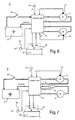
- Fig. 6 illustrates a control system, in which an approximation according to the second basic embodiment is employed.
- this control system only measurement of the blade energy p1 is used for protection of the battery 4.
- a blade motor energy monitor 30 is associated with the blade motor 8.
- the blade motor energy monitor 30 measures the energy consumption p1 of the blade motor 8 and is connected to the control unit 10.
- a maximum blade motor energy selector 32 is provided for selecting a predetermined maximum blade motor energy value p1*. This maximum value p1* is compared with the actual blade motor energy consumption p1 of the blade motor 8.
- the predetermined speed v* will be reduced as soon as the energy consumption p1 of the blade motor 8 exceeds the predetermined maximum blade motor energy value p1*.
- this is the case in the time interval E, not in the time intervals D and F. It will be realized that, as apposed to Fig. 4 , a total energy monitor 16 is not used. In this case, it is sufficient to use the blade motor energy monitor 30.
- Fig. 7 is illustrated an embodiment similar to the embodiment of Fig. 6 , yet in which the blade energy monitor 30 for monitoring the blade energy p1 is replaced by a blade motor current sensor 34.
- the value i1 derived from this sensor 34 is also introduced into the control unit 10.
- a blade motor maximum current selector 36 provides a maximum blade current i1*.
- a blade load monitor 38 is used for monitoring the blade load 11.
- the blade load monitor 38 is connected to the control unit 10.
- This selector 40 provides a predetermined maximum blade load value l1*
- the control unit 10 determines when the total energy p, preferably the speed v, has to be reduced. In the example shown, this is the case in the time interval E.
Landscapes
- Life Sciences & Earth Sciences (AREA)
- Environmental Sciences (AREA)
- Harvester Elements (AREA)
Applications Claiming Priority (2)
| Application Number | Priority Date | Filing Date | Title |
|---|---|---|---|
| CN2009101354553A CN101861781B (zh) | 2009-04-17 | 2009-04-17 | 自驱式割草机 |
| PCT/CN2010/071857 WO2010118703A1 (zh) | 2009-04-17 | 2010-04-16 | 自驱式割草机 |
Publications (2)
| Publication Number | Publication Date |
|---|---|
| EP2420130A1 true EP2420130A1 (de) | 2012-02-22 |
| EP2420130A4 EP2420130A4 (de) | 2013-09-25 |
Family
ID=42953886
Family Applications (1)
| Application Number | Title | Priority Date | Filing Date |
|---|---|---|---|
| EP10764116.9A Withdrawn EP2420130A4 (de) | 2009-04-17 | 2010-04-16 | Selbstangetriebener rasenmäher |
Country Status (4)
| Country | Link |
|---|---|
| US (1) | US20130167495A1 (de) |
| EP (1) | EP2420130A4 (de) |
| CN (1) | CN101861781B (de) |
| WO (1) | WO2010118703A1 (de) |
Cited By (6)
| Publication number | Priority date | Publication date | Assignee | Title |
|---|---|---|---|---|
| EP2868513A1 (de) * | 2013-10-31 | 2015-05-06 | Deere & Company | System zur Verwaltung der Leistung einer elektrischen Einrichtung |
| CN106257820A (zh) * | 2016-08-25 | 2016-12-28 | 珠海市磐石电子科技有限公司 | 电机多模态控制方法及系统 |
| EP2639128A3 (de) * | 2012-03-13 | 2018-05-02 | Kanzaki Kokyukoki Mfg. Co., Ltd. | Nutzfahrzeug |
| EP3326444A1 (de) * | 2016-11-28 | 2018-05-30 | Honda Motor Co., Ltd. | Elektrisches gerät |
| CN109076773A (zh) * | 2017-06-13 | 2018-12-25 | 迪尔公司 | 电动手扶式草地用割草机 |
| WO2020174046A1 (de) * | 2019-02-28 | 2020-09-03 | Robert Bosch Gmbh | Angetriebene bodenpflegevorrichtung |
Families Citing this family (15)
| Publication number | Priority date | Publication date | Assignee | Title |
|---|---|---|---|---|
| CN102484964B (zh) * | 2010-12-01 | 2014-12-10 | 天佑电器(苏州)有限公司 | 无绳电动工具 |
| AU2011372806B2 (en) * | 2011-07-14 | 2015-07-16 | Husqvarna Ab | Battery powered lawn care vehicle with efficient drive controller |
| AU2011372794B2 (en) | 2011-07-14 | 2016-05-12 | Husqvarna Ab | Battery powered lawn care vehicle with drive efficiency indicator |
| US9699965B2 (en) | 2011-07-14 | 2017-07-11 | Husqvarna Ab | Articulated riding lawn mower including distributed battery system |
| JP6112835B2 (ja) * | 2012-11-26 | 2017-04-12 | キヤノン株式会社 | 振動型アクチュエータの駆動装置及び駆動制御方法 |
| DE102014206268A1 (de) * | 2014-04-02 | 2015-10-08 | Robert Bosch Gmbh | Werkzeugmaschine, insbesondere Rasenmäher, Verfahren zum Betreiben |
| US10845804B2 (en) * | 2014-12-18 | 2020-11-24 | Husqvarna Ab | Parcel mapping via electrical resistance detection of a robotic vehicle |
| US10148207B2 (en) | 2015-10-16 | 2018-12-04 | Kohler Co. | Segmented waveform converter on controlled field variable speed generator |
| US10148202B2 (en) | 2015-10-16 | 2018-12-04 | Kohler Co. | Hybrid device with segmented waveform converter |
| US10778123B2 (en) | 2015-10-16 | 2020-09-15 | Kohler Co. | Synchronous inverter |
| US10063097B2 (en) | 2015-10-16 | 2018-08-28 | Kohler Co. | Segmented waveform converter on controlled field variable speed generator |
| CN115315177A (zh) * | 2019-10-11 | 2022-11-08 | 艾瑞斯公司 | 用于割草机的电源和控制系统 |
| TWI735242B (zh) * | 2020-05-26 | 2021-08-01 | 優式機器人股份有限公司 | 自動除草設備及其運作方法 |
| CN111837588B (zh) * | 2020-08-07 | 2021-10-26 | 格力博(江苏)股份有限公司 | 割草车系统、割刀转速设置方法及割草车系统管理方法 |
| CN115428642A (zh) * | 2021-06-02 | 2022-12-06 | 苏州宝时得电动工具有限公司 | 智能割草机控制方法、装置、智能割草机和计算机设备 |
Citations (4)
| Publication number | Priority date | Publication date | Assignee | Title |
|---|---|---|---|---|
| US5442901A (en) * | 1994-07-22 | 1995-08-22 | Ryobi North America | Self-propelled mower |
| GB2303719A (en) * | 1995-07-26 | 1997-02-26 | Black & Decker Inc | Control device for an electric motor |
| WO1997028681A2 (en) * | 1996-02-09 | 1997-08-14 | The Toro Company | Electric drive riding mower |
| EP1452084A2 (de) * | 2003-02-11 | 2004-09-01 | Textron Inc. | Batteriegetriebener, handgeführter Rasenmäher |
Family Cites Families (13)
| Publication number | Priority date | Publication date | Assignee | Title |
|---|---|---|---|---|
| US5007234A (en) * | 1989-11-27 | 1991-04-16 | Shurman Darlene M | Automatic self-guiding lawn mower and mowing method |
| US5163273A (en) * | 1991-04-01 | 1992-11-17 | Wojtkowski David J | Automatic lawn mower vehicle |
| JP3141895B2 (ja) * | 1991-07-20 | 2001-03-07 | スズキ株式会社 | 電動車両用モータ制御回路 |
| US5809755A (en) * | 1994-12-16 | 1998-09-22 | Wright Manufacturing, Inc. | Power mower with riding platform for supporting standing operator |
| JPH09201126A (ja) * | 1995-11-24 | 1997-08-05 | Honda Motor Co Ltd | 電動芝刈機 |
| US5934051A (en) * | 1997-02-06 | 1999-08-10 | Textron, Inc. | Solid state mow system for electrically powered mower |
| JP4010239B2 (ja) * | 2002-12-11 | 2007-11-21 | 日立工機株式会社 | 回転数制御装置 |
| US20060059879A1 (en) * | 2004-09-20 | 2006-03-23 | Edmond Brian W | Multifunction electric tractor |
| KR100645808B1 (ko) * | 2004-12-08 | 2006-11-23 | 엘지전자 주식회사 | 모터 제어방법 |
| US7367173B2 (en) * | 2005-03-02 | 2008-05-06 | Textron Inc. | Greens mower data display and controller |
| US7677017B2 (en) * | 2005-06-28 | 2010-03-16 | Textron Innovations Inc. | Modular power source for walk-behind mower |
| US7728534B2 (en) * | 2006-10-17 | 2010-06-01 | Mtd Products Inc | Hybrid electric lawnmower |
| US7594377B1 (en) * | 2006-10-27 | 2009-09-29 | Sauer-Danfoss Inc. | Means of adjusting ground speed of a vehicle based on load on blade assembly |
-
2009
- 2009-04-17 CN CN2009101354553A patent/CN101861781B/zh not_active Expired - Fee Related
-
2010
- 2010-04-16 US US13/264,894 patent/US20130167495A1/en not_active Abandoned
- 2010-04-16 EP EP10764116.9A patent/EP2420130A4/de not_active Withdrawn
- 2010-04-16 WO PCT/CN2010/071857 patent/WO2010118703A1/zh active Application Filing
Patent Citations (4)
| Publication number | Priority date | Publication date | Assignee | Title |
|---|---|---|---|---|
| US5442901A (en) * | 1994-07-22 | 1995-08-22 | Ryobi North America | Self-propelled mower |
| GB2303719A (en) * | 1995-07-26 | 1997-02-26 | Black & Decker Inc | Control device for an electric motor |
| WO1997028681A2 (en) * | 1996-02-09 | 1997-08-14 | The Toro Company | Electric drive riding mower |
| EP1452084A2 (de) * | 2003-02-11 | 2004-09-01 | Textron Inc. | Batteriegetriebener, handgeführter Rasenmäher |
Non-Patent Citations (1)
| Title |
|---|
| See also references of WO2010118703A1 * |
Cited By (10)
| Publication number | Priority date | Publication date | Assignee | Title |
|---|---|---|---|---|
| EP2639128A3 (de) * | 2012-03-13 | 2018-05-02 | Kanzaki Kokyukoki Mfg. Co., Ltd. | Nutzfahrzeug |
| EP2868513A1 (de) * | 2013-10-31 | 2015-05-06 | Deere & Company | System zur Verwaltung der Leistung einer elektrischen Einrichtung |
| US9475497B2 (en) | 2013-10-31 | 2016-10-25 | Deere & Company | Electric implement power management system |
| CN106257820A (zh) * | 2016-08-25 | 2016-12-28 | 珠海市磐石电子科技有限公司 | 电机多模态控制方法及系统 |
| CN106257820B (zh) * | 2016-08-25 | 2019-06-28 | 珠海市磐石电子科技有限公司 | 电机多模态控制方法及系统 |
| EP3326444A1 (de) * | 2016-11-28 | 2018-05-30 | Honda Motor Co., Ltd. | Elektrisches gerät |
| US10158302B2 (en) | 2016-11-28 | 2018-12-18 | Honda Motor Co., Ltd. | Electric power equipment |
| CN109076773A (zh) * | 2017-06-13 | 2018-12-25 | 迪尔公司 | 电动手扶式草地用割草机 |
| US11700787B2 (en) | 2017-06-13 | 2023-07-18 | Deere & Company | Electric walk behind greens mower |
| WO2020174046A1 (de) * | 2019-02-28 | 2020-09-03 | Robert Bosch Gmbh | Angetriebene bodenpflegevorrichtung |
Also Published As
| Publication number | Publication date |
|---|---|
| US20130167495A1 (en) | 2013-07-04 |
| CN101861781B (zh) | 2013-04-03 |
| WO2010118703A1 (zh) | 2010-10-21 |
| CN101861781A (zh) | 2010-10-20 |
| EP2420130A4 (de) | 2013-09-25 |
Similar Documents
| Publication | Publication Date | Title |
|---|---|---|
| EP2420130A1 (de) | Selbstangetriebener rasenmäher | |
| US7728534B2 (en) | Hybrid electric lawnmower | |
| US9257925B2 (en) | Speed control for power tools | |
| US8286721B2 (en) | Electric power hoe | |
| JP5671198B2 (ja) | 手持ち式作業機および電動モータの制御方法 | |
| US5906088A (en) | Electric lawn mower | |
| US7741793B2 (en) | Hybrid electric device | |
| US7479754B2 (en) | Hybrid electric lawnmower | |
| US9787225B2 (en) | Hybrid electric device | |
| US5937622A (en) | Cordless electric lawn mower having energy management control system | |
| US7884560B2 (en) | Hybrid electric device | |
| KR101160478B1 (ko) | 모터 구동식 예초기 | |
| EP0841000B1 (de) | Batteriebetriebener Fadenschneider | |
| US20070125056A1 (en) | Multifunction electric tractor with an implement | |
| US20080120955A1 (en) | Hybrid electric lawnmower | |
| US9113596B2 (en) | Hybrid electric turf mower with power shed and power boost | |
| ES2430114T3 (es) | Herramienta de trabajo con un motor de accionamiento eléctrico | |
| US20230221371A1 (en) | Power unit including multiple battery packs for use with outdoor power equipment | |
| US20240081177A1 (en) | Mower with ganged reel cutting units having automatic clip control in both straight ahead motion and in turns | |
| US6949898B2 (en) | Hybrid type working machine | |
| JP2013110899A (ja) | 補助電源の付いた電動モータ制御機構 | |
| JP2023152732A (ja) | 電動作業車両 | |
| JP2022151417A (ja) | 電動刈払機の制御装置 |
Legal Events
| Date | Code | Title | Description |
|---|---|---|---|
| PUAI | Public reference made under article 153(3) epc to a published international application that has entered the european phase |
Free format text: ORIGINAL CODE: 0009012 |
|
| 17P | Request for examination filed |
Effective date: 20111014 |
|
| AK | Designated contracting states |
Kind code of ref document: A1 Designated state(s): AT BE BG CH CY CZ DE DK EE ES FI FR GB GR HR HU IE IS IT LI LT LU LV MC MK MT NL NO PL PT RO SE SI SK SM TR |
|
| DAX | Request for extension of the european patent (deleted) | ||
| A4 | Supplementary search report drawn up and despatched |
Effective date: 20130827 |
|
| RIC1 | Information provided on ipc code assigned before grant |
Ipc: H02P 7/00 20060101ALI20130821BHEP Ipc: A01D 69/02 20060101AFI20130821BHEP Ipc: A01D 34/00 20060101ALI20130821BHEP Ipc: A01D 34/58 20060101ALI20130821BHEP Ipc: A01D 34/47 20060101ALI20130821BHEP |
|
| RIC1 | Information provided on ipc code assigned before grant |
Ipc: H02P 7/00 20060101ALI20140217BHEP Ipc: A01D 34/47 20060101ALI20140217BHEP Ipc: A01D 34/00 20060101ALI20140217BHEP Ipc: A01D 69/02 20060101AFI20140217BHEP Ipc: A01D 34/58 20060101ALI20140217BHEP |
|
| GRAP | Despatch of communication of intention to grant a patent |
Free format text: ORIGINAL CODE: EPIDOSNIGR1 |
|
| INTG | Intention to grant announced |
Effective date: 20140423 |
|
| RIN1 | Information on inventor provided before grant (corrected) |
Inventor name: BORINATO, GIANNI |
|
| 17Q | First examination report despatched |
Effective date: 20140829 |
|
| STAA | Information on the status of an ep patent application or granted ep patent |
Free format text: STATUS: THE APPLICATION IS DEEMED TO BE WITHDRAWN |
|
| 18D | Application deemed to be withdrawn |
Effective date: 20150109 |