EP2418757A1 - Stator for electric machine - Google Patents
Stator for electric machine Download PDFInfo
- Publication number
- EP2418757A1 EP2418757A1 EP10761627A EP10761627A EP2418757A1 EP 2418757 A1 EP2418757 A1 EP 2418757A1 EP 10761627 A EP10761627 A EP 10761627A EP 10761627 A EP10761627 A EP 10761627A EP 2418757 A1 EP2418757 A1 EP 2418757A1
- Authority
- EP
- European Patent Office
- Prior art keywords
- coils
- series
- phase
- stator core
- coil
- Prior art date
- Legal status (The legal status is an assumption and is not a legal conclusion. Google has not performed a legal analysis and makes no representation as to the accuracy of the status listed.)
- Withdrawn
Links
- 239000000203 mixture Substances 0.000 claims abstract description 5
- 238000004804 winding Methods 0.000 description 4
- 238000010586 diagram Methods 0.000 description 3
- XEEYBQQBJWHFJM-UHFFFAOYSA-N Iron Chemical compound [Fe] XEEYBQQBJWHFJM-UHFFFAOYSA-N 0.000 description 2
- 238000009413 insulation Methods 0.000 description 2
- 238000000034 method Methods 0.000 description 2
- 230000007935 neutral effect Effects 0.000 description 2
- 229920003002 synthetic resin Polymers 0.000 description 2
- 239000000057 synthetic resin Substances 0.000 description 2
- 229910000831 Steel Inorganic materials 0.000 description 1
- 238000005452 bending Methods 0.000 description 1
- 230000006866 deterioration Effects 0.000 description 1
- 238000003780 insertion Methods 0.000 description 1
- 230000037431 insertion Effects 0.000 description 1
- 229910052742 iron Inorganic materials 0.000 description 1
- 238000010030 laminating Methods 0.000 description 1
- 239000000696 magnetic material Substances 0.000 description 1
- 238000012986 modification Methods 0.000 description 1
- 230000004048 modification Effects 0.000 description 1
- 239000010959 steel Substances 0.000 description 1
Images





Classifications
-
- H—ELECTRICITY
- H02—GENERATION; CONVERSION OR DISTRIBUTION OF ELECTRIC POWER
- H02K—DYNAMO-ELECTRIC MACHINES
- H02K1/00—Details of the magnetic circuit
- H02K1/06—Details of the magnetic circuit characterised by the shape, form or construction
- H02K1/12—Stationary parts of the magnetic circuit
- H02K1/18—Means for mounting or fastening magnetic stationary parts on to, or to, the stator structures
-
- H—ELECTRICITY
- H02—GENERATION; CONVERSION OR DISTRIBUTION OF ELECTRIC POWER
- H02K—DYNAMO-ELECTRIC MACHINES
- H02K3/00—Details of windings
- H02K3/04—Windings characterised by the conductor shape, form or construction, e.g. with bar conductors
- H02K3/12—Windings characterised by the conductor shape, form or construction, e.g. with bar conductors arranged in slots
-
- H—ELECTRICITY
- H02—GENERATION; CONVERSION OR DISTRIBUTION OF ELECTRIC POWER
- H02K—DYNAMO-ELECTRIC MACHINES
- H02K1/00—Details of the magnetic circuit
- H02K1/06—Details of the magnetic circuit characterised by the shape, form or construction
- H02K1/12—Stationary parts of the magnetic circuit
- H02K1/16—Stator cores with slots for windings
-
- H—ELECTRICITY
- H02—GENERATION; CONVERSION OR DISTRIBUTION OF ELECTRIC POWER
- H02K—DYNAMO-ELECTRIC MACHINES
- H02K3/00—Details of windings
- H02K3/04—Windings characterised by the conductor shape, form or construction, e.g. with bar conductors
-
- H—ELECTRICITY
- H02—GENERATION; CONVERSION OR DISTRIBUTION OF ELECTRIC POWER
- H02K—DYNAMO-ELECTRIC MACHINES
- H02K3/00—Details of windings
- H02K3/04—Windings characterised by the conductor shape, form or construction, e.g. with bar conductors
- H02K3/28—Layout of windings or of connections between windings
Definitions
- the present invention relates to a stator for an electric machine including a first and second series of coils each formed into a predetermined shape.
- Patent Document 1 As an electric machine in which U-phase, V-phase and W-phase coils are wound around teeth of a stator core in a distributed winding manner, there is a motor described in Patent Document 1.
- the motor described in the Patent Document 1 when coils of the phases are assembled into slots, in order to avoid contact between coil ends of the coils of different phases, the coil ends are previously formed into predetermined shapes. By forming the coil ends into the predetermined shapes, the coil is prevented from being damaged when the coil is assembled into the slot using an inserter, the space factor of the coil is enhanced, and there is no need to form the coil end after the coil is assembled into the slot.
- a coil end of the U-phase coil is formed so that slots into which the V phase coil and the W-phase coil are assembled thereafter can be seen from an axial direction of a stator. That is, the coil end of the U-phase coil is formed such that a bridge portion thereof extends in an arcuate shape and radially outward of the stator core as compared with slots into which the V phase coil and the W-phase coil are assembled.
- the coil end of the V-phase coil is formed to incline radially outward of the stator core from a location slightly separated away from an end surface of the stator core in its axial direction.
- the V-phase coil is disposed on the U-phase coil in a state where the V-phase coil is assembled into the slot.
- the coil end of the W-phase coil is formed into such a shape that the coil end stays within a region other than portions where the U-phase coil and the V-phase coil are disposed.
- a bridge portion of the coil end of the W-phase coil is formed such that it is disposed radially inside a bridge portion of the coil end of the V-phase coil in the stator core.
- a stator for an electric machine includes a stator core, a plurality of teeth, a first series of coils, and a second series of coils.
- the teeth extend into a first direction from the stator core and are arranged such that a slot is formed between adjacent teeth.
- the first series of coils are assembled into the slots and are formed into predetermined shapes.
- the second series of coils are assembled into the slots and are formed into predetermined shapes.
- Each of the first series of coils includes a pair of inserting portions respectively inserted into the slots, and a pair of first coil ends protruding from both end surfaces of the stator core.
- Each of the first coil ends includes a pair of bent portions extending from ends of the pair of inserting portions into a second direction that is opposite to the first direction, and a bridge portion that connects the bent portions with each other.
- Each of the second series of coils includes a pair of inserting portions respectively inserted into the slots, and second coil ends protruding from both end surfaces of the stator core.
- Each of the second coil ends includes a pair of upright portions extending from ends of the pair of inserting portions, and a bridge portion that connects the upright portions with each other.
- the bridge portions of the first series of coils are disposed on the side toward the second direction with respect to the bridge portions of the second series of coils.
- the bridge portions of the second series of coils each extend across the bent portions of two adjacent first series of coils.
- the first series of coils and the second series of coils are configured so that each series includes a mixture of coils of at least two phases among a U-phase, a V-phase and a W-phase, and each of the coils in the first series is connected to a coil of the same phase in the second series.
- a stator of an electric machine according to one embodiment of the present invention will be described below with reference to Figs. 1 to 7 .
- a rotational electric machine M as an electric machine includes a stator 10 and a rotor 15 as a movable element that is rotatably mounted inside of the stator 10.
- the stator 10 includes an annular stator core 11, a plurality of stationary teeth 12, and a plurality of split teeth 13, which are arranged along a circumferential direction and radially inside the stator core 11, U-phase, V-phase and W-phase outer coils 30U, 30V and 30W as first series of coils, and U-phase, V-phase and W-phase inner coils 40U, 40V and 40W as second series of coils, which are assembled into slots.
- the number of the stationary teeth 12 is twelve
- the number of the split teeth 13 is twelve
- the number of slots 14 is twenty-four24.
- the slots 14 are arranged along a circumferential direction of the stator core 11 at equal pitch.
- the stator core 11 is configured by laminating a plurality of core plates made of magnetic material (steel plates) on one another in an axial direction. As shown in Figs. 2 and 3(a) , the plurality of stationary teeth 12 are integrally formed on an inner circumferential surface of the stator core 11.
- the stationary teeth 12 extend radially inward of the stator core 11, i.e., in a first direction toward a center axis P of the stator core 11 from the inner circumferential surface of the stator core 11.
- the stationary teeth 12 extend over the entire axial direction of the stator core 11.
- Engaging projections 11a are formed at intermediate locations between stationary teeth 12 that are adjacent to each other in the circumferential direction of the stator core 11 on the inner circumferential surface of the stator core 11 such that the engaging projections 11a extend over the entire axial direction of the stator core 11.
- the engaging projections 11a are formed in a tapered shape such that their widths are gradually increased toward the center axis P (central portion) of the stator core 11 from the inner circumferential surface of the stator core 11.
- each of the split teeth 13 has a rectangular plate shape and its longitudinal size (size along the axial direction of the stator core 11) is the same as the size of the stator core 11 in its axial direction.
- An engaging recess 13c is formed on a proximal end surface of each of the split teeth 13 so as to extend over the entire split teeth 13 in its longitudinal direction.
- the engaging recess 13c is formed in a tapered shape such that its width is gradually increased toward its distal end surface from the proximal end surface of the split tooth 13.
- the engaging projections 11a of the stator core 11 are fitted into the engaging recesses 13c of the split teeth 13, thereby attaching the split teeth 13 to the stator core 11.
- the engaging projections 11a are engaged with the engaging recesses 13c, thereby preventing the split teeth 13 from moving radially inward of the stator core 11.
- the split teeth 13 are attached to the stator core 11, thereby defining the slots 14 between the stationary teeth 12 and the split teeth 13 that are adjacent to each other in the circumferential direction of the stator core 11.
- Each of the slots 14 has a rectangular shape as viewed from above.
- the U-phase, V-phase and W-phase outer coils 30U, 30V and 30W are wound around the stationary teeth 12 in the distributed winding manner. There are pairs for the U-phase, V-phase and W-phase outer coils 30U, 30V and 30W. All of the outer coils 30U, 30V and 30W are disposed on one circumference around the center axis P of the stator core 11. Each of the outer coils 30U, 30V and 30W is assembled into two stationary teeth 12 so as to extend across two slots 14 and two stationary teeth 12 while sandwiching one split tooth 13 therebetween. Coils of different phases are not inserted into the same slot 14.
- the pair of outer coils 30U is disposed at an angular distance of 180° from each other, and is inserted into a total of four slots 14. Eight slots 14 exist between a slot 14 into which one of the outer coils 30U is inserted and a slot 14 into which the other outer coil 30U is inserted.
- the outer coils 30V and the outer coils 30W are disposed also in the same manner.
- the outer coils 30U, 30V and 30W are coil wires (rectangular wires) having rectangular cross sections and uniform widths, and they are insulated and coated.
- each of the outer coils 30U, 30V and 30W (only outer coil 30U is shown in Fig. 4(a) ) includes a pair of inserting portions 37 inserted into the slots 14, and a pair of coil ends 31 (first coil ends) protruding from both end surfaces of the stator core 11 in its axial direction.
- the coil end 31 of each of the outer coils 30U, 30V and 30W (hereinafter, referred to as an outer coil end 31) includes a pair of bent portions 31a, which are bent so as to extend radially outward of the stator core 11 (second direction opposite to the first direction) from the inserting portions 37. Further, each of the outer coil ends 31 includes an outer bridge portion 31b, which extends along the circumferential direction of the stator core 11 so as to connect distal ends of the pair of bent portions 31a with each other. Each of the outer coil ends 31 is formed by the pair of bent portions 31a and the outer bridge portions 31b into a channel shape as viewed from above.
- the outer bridge portions 31b are formed into predetermined shapes so as to extend along the circumferential direction of the stator core 11.
- the outer bridge portion 31b is disposed radially outside the inner circumferential surface (this corresponds to a bottom of the slot 14) of the stator core 11 in the stator core 11.
- the U-phase, V-phase and W-phase inner coils 40U, 40V and 40W as the second series of coils are wound around the stationary teeth 12 in the distributed winding manner.
- Each of the inner coils 40U, 40V and 40W is assembled into the two stationary teeth 12 so as to extend across two slots 14 and two stationary teeth 12 that sandwich one split tooth 13 therebetween. Coils of different phases are not inserted into the same slot 14.
- the pair of inner coils 40U is disposed at an angular distance of 180° from each other, and is inserted into a total of four slots 14.
- the inner coils 40V and the inner coils 40W are disposed also in the same manner.
- the inner coils 40U, 40V and 40W are coil wires (rectangular wires) having rectangular cross sections and uniform widths, and they are insulated and coated.
- each of the inner coils 40U, 40V and 40W (only inner coil 40U is shown in Fig. 4(b) ) includes a pair of inserting portions 47 inserted into the slots 14, and a pair of coil ends 41 (second coil ends) protruding from both end surfaces of the stator core 11 in its axial direction.
- the coil end 41 (hereinafter, referred to as an inner coil end 41) of each of the inner coils 40U, 40V and 40W includes a pair of upright portions 41a extending from the inserting portions 47 along the axial direction of the stator core 11.
- the inner coil end 41 further includes an inner bridge portion 41b extending along the circumferential direction of the stator core 11 so as to connect distal ends of the pair of upright portions 41a with each other.
- Each of the inner coil ends 41 is formed by the pair of upright portions 41a and the pair of inner bridge portions 41b into a channel shape as viewed from the front.
- an insulation sheet 32 made of synthetic resin is wound around each of the inserting portions 47.
- the outer bridge portions 31b are disposed outside the inner bridge portions 41b in the radial direction of the stator core 11.
- the outer bridge portions 31b are disposed on the opposite side from the rotor 15 with respect to the inner bridge portions 41b.
- the outer bridge portions 31b are disposed on a first circumference around the center axis P of the stator core 11, and the inner bridge portions 41b are disposed on a second circumference located radially inside the first circumference.
- the inserting portions 37 and 47 of the outer and inner coils are disposed on the second circumference.
- Each of the inner bridge portions 41b extends across the bent portions 31a of two outer coils 30U that are adjacent to each other in the circumferential direction of the stator core 11.
- teeth that are adjacent to the upright portions 41a between the pair of upright portions 41a of each of the inner coil ends 41 are the stationary teeth 12.
- Teeth sandwiched between the outer bridge portion 31b and the inner bridge portion 41b that partially overlaps the outer bridge portion 31b in the circumferential direction are the stationary teeth 12.
- the outer coils 30U, 30V and 30W are assembled into the stator core 11 prior to the inner coils 40U, 40V and 40W.
- each of the outer coils 30U, 30V and 30W is assembled into the two (pair of) stationary teeth 12 that sandwich one engaging projection 11a. That is, each of the outer coils 30U, 30V and 30W is moved radially outward of the stator core 11.
- Each of the outer coils 30U, 30V and 30W is assembled into a pair of stationary teeth 12 such that the pair of stationary teeth 12 is disposed inside the outer coils 30U, 30V and 30W.
- the pairs of U-phase, V-phase and W-phase outer coils 30U, 30V and 30W are assembled into the stationary teeth 12 (stator core 11) such that they are disposed on the same circumference in the order of U-phase, V-phase and W-phase along the circumferential direction of the stator core 11.
- gaps into which split teeth 13 can be inserted are formed between the U-phase outer coil 30U and the V-phase outer coil 30V that are adjacent to each other in the circumferential direction, between the V-phase outer coil 30V and the W-phase outer coil 30W that are adjacent to each other in the circumferential direction, and between the W-phase outer coil 30W and the U-phase outer coil 30U that are adjacent to each other in the circumferential direction.
- the split teeth 13 are inserted into gaps each formed between two of the outer coils 30U, 30V and 30W that are adjacent to each other in the circumferential direction of the stator core 11, and the split teeth 13 are attached to the stator core 11. While moving the split teeth 13 along the axial direction of the stator core 11, the engaging recesses 13c of the split teeth 13 are fitted to the engaging projections 11a of the stator core 11, thereby attaching the split teeth 13 to the stator core 11.
- the slots 14 are defined between the stationary teeth 12 and the split teeth 13 that are adjacent to each other in the circumferential direction of the stator core 11.
- the inserting portions 37 of the outer coils 30U, 30V and 30W are inserted into the defined slots 14.
- the bent portions 31a of the outer coil ends 31 extend from the inserting portions 37 (the slots 14) radially outward of the stator core 11.
- gaps are formed between the bent portions 31a of the outer coil ends 31 that are adjacent to each other in the circumferential direction, and the engaging projections 11a are opened in the axial direction of the stator core 11 in the gaps. That is, the bent portions 31a do not exist on extensions of the engaging projections 11a along the axial direction of the stator core 11.
- each of the inner coils 40U, 40V and 40W is assembled into two (pair of) stationary teeth 12 that sandwich one split tooth 13. That is, each of the inner coils 40U, 40V and 40W is assembled into stationary tooth 12 across which the inner bridge portion 41b and the outer bridge portion 31b extend.
- Each of the inner coils 40U, 40V and 40W is moved radially outward of the stator core 11 from an inner space of the stator core 11, and each of the inner coils 40U, 40V and 40W is assembled into a pair of stationary teeth 12 such that the same pair of stationary teeth 12 (and one split tooth 13 between the same pair of stationary teeth 12) are disposed inside the inner coils 40U, 40V and 40W.
- the outer bridge portion 31b is disposed radially outside the inner circumferential surface (this corresponds to the bottom of the slot 14) of the stator core 11, and a gap is formed between the pair of bent portions 31a on both ends of the outer bridge portion 31b.
- the outer bridge portions 31b do not hinder assembling of the inner coils 40U, 40V and 40W.
- the inserting portions 37 are accommodated in the gaps between the stationary teeth 12; and each of the inner bridge portions 41b extends across two bent portions 31a, which are adjacent to each other in the circumferential direction of the stator core 11, and is disposed radially inside the outer bridge portion 31b.
- the pairs of U-phase, V-phase and W-phase inner coils 40U, 40V and 40W are assembled into the stationary teeth 12 such that the inner coils 40U, 40V and 40W are disposed on the same circumference (in the same series) in the order of U-phase, V-phase and W-phase.
- gaps into which the split teeth 13 can be inserted are formed between the U-phase inner coil 40U and the V-phase inner coil 40V that are adjacent to each other in the circumferential direction, between the V-phase inner coil 40V and the W-phase inner coil 40W that are adjacent to each other in the circumferential direction, and between the W-phase inner coil 40W and the U-phase inner coil 40U that are adjacent to each other in the circumferential direction.
- the split teeth 13 are inserted into gaps between two of the inner coils 40U, 40V and 40W that are adjacent to each other in the circumferential direction of the stator core 11, and the split teeth 13 are attached to the stator core 11.
- the outer bridge portions 31b are disposed radially outside the inner circumferential surface of the stator core 11, and are disposed radially outside the engaging projections 11a of the stator core 11. Gaps that are opened in the axial direction of the stator core 11 are formed between the two bent portions 31a disposed between the stationary teeth 12 that are adjacent to each other in the circumferential direction. Hence, the outer bridge portions 31b and the bent portions 31a do not hinder the insertion of the split teeth 13.
- the split teeth 13 are attached to the stator core 11 such that the split teeth 13 and the stationary teeth 12 sandwich the inserting portions 47 of the inner coils 40U, 40V and 40W.
- the engaging recesses 13c of the split teeth 13 are fitted to the engaging projections 11a of the stator core 11 while moving the split teeth 13 along the axial direction of the stator core 11, thereby attaching the split teeth 13 to the stator core 11.
- the slots 14 are defined between the stationary teeth 12 and the split teeth 13 that are adjacent to each other in the circumferential direction.
- the inserting portions 47 of the inner coils 40U, 40V and 40W are inserted into the slots 14.
- Fig. 7 is a wiring diagram of the outer coils 30U, 30V and 30W and the inner coils 40U, 40V and 40W in the stator 10 produced by the above-described method.
- U-phase inserting portions (shown with 37U in Fig. 7 only) of a pair of outer coils 30U that are connected to a U-phase terminal 51 of an inverter 50 pass through a group of the U-phase slots (shown with 14Uo in Fig. 7 only).
- V-phase inserting portions (shown with 37V in Fig. 7 only) of a pair of outer coils 30V that are connected to a V-phase terminal 52 of the inverter 50 pass through a group of the V-phase slots (shown with 14Vo in Fig. 7 only).
- W-phase inserting portions (shown with 37W in Fig. 7 only) of a pair of outer coils 30W that are connected to a W-phase terminal 53 of the inverter 50 pass through a group of the W-phase slots (shown with 14Wo in Fig. 7 only).
- U-phase inserting portions (shown with 47U in Fig. 7 only) of a pair of inner coils 40U that are connected to the U-phase terminal 51 of the inverter 50 pass through a group of the U-phase slots (shown with 14Ui in Fig. 7 only).
- V-phase inserting portions (shown with 47V in Fig. 7 only) of a pair of inner coils 40V that are connected to the V-phase terminal 52 of the inverter 50 pass through a group of the V-phase slots (shown with 14Vi in Fig. 7 only).
- W-phase inserting portions (shown with 47W in Fig. 7 only) of a pair of inner coils 40W that are connected to the W-phase terminal 53 of the inverter 50 pass through a group of the W-phase slots (shown with 14Wi in Fig. 7 only).
- the U-phase outer coil 30U and the U-phase inner coil 40U are connected to each other in series.
- the U-phase coils the same number of first series of outer coils 30U and second series of inner coils 40U are used (two each).
- the V-phase outer coil 30V and the V-phase inner coil 40V are connected to each other in series.
- the same number of first series of outer coils 30V and second series of inner coils 40V are used (two each).
- the W-phase outer coil 30W and the W-phase inner coil 40W are connected to each other in series.
- the same number of first series of outer coils 30W and second series of inner coils 40W are used (two each).
- a symbol N1 represents a neutral point that connects terminal ends of coil wires 33, 34 and 43 of the outer coils 30U, 30V and 30W and the inner coils 40U, 40V and 40W with each other
- a symbol N2 represents a neutral point that connects terminal ends of coil wires 35, 36 and 44 of the outer coils 30U, 30V and 30W and the inner coils 40U, 40V and 40W.
- the rotational electric machine M is an 8-pole 3-phase 24-slot rotational electric machine.
- the rotor 15 is rotated by energizing the outer coils 30U, 30V and 30W and the inner coils 40U, 40V and 40W through the inverter 50.
- This embodiment has the following merits.
- the outer coils 30U, 30V and 30W are not necessarily formed into the same shapes.
- the lengths of the coil wires may be different from one phase to another.
- the second series of inner coils 40U, 40V and 40W of the respective phases are not necessarily formed into the same shapes as long as the inner bridge portions 41b extend across the bent portion 31a, and the lengths or the like of the coil wires may be different from one phase to another.
- the first series of coils may be configured so that the series include a mixture of coils of at least two phases (U-phase and V-phase, V-phase and W-phase, or W-phase and U-phase), and the second series of coils may be configured so that the series include a mixture of coils of at least two phases (V-phase and W-phase, W-phase and U-phase, or U-phase and V-phase)
- the first series of coils are first outer coils 301 U, 301V and 301W and second outer coils 302U, 302V and 302W, which are disposed inside the first outer coils 301 U, 301V and 301W in the radial direction of the stator core 11.
- second series of coils are first inner coils 401 U, 401V and 401W and second inner coils 402U, 402V and 402W, which are disposed inside of the first inner coils 401 U, 401V and 401W in the radial direction of the stator core 11.
- All of the teeth may be the stationary teeth 12 or all of the teeth may be the split teeth 13.
- a stator of a straight type electric machine such as a linear motor may be formed as in the present invention.
- an outer coil first series of coil
- an inner coil second series of coil
- an inner coil means a coil that is assembled into the stator core after the outer coil, and its bridge portion is disposed on a side of the protruding direction of the teeth as compared with the bridge portion of the outer coil.
Landscapes
- Engineering & Computer Science (AREA)
- Power Engineering (AREA)
- Windings For Motors And Generators (AREA)
- Iron Core Of Rotating Electric Machines (AREA)
- Manufacture Of Motors, Generators (AREA)
Abstract
Description
- The present invention relates to a stator for an electric machine including a first and second series of coils each formed into a predetermined shape.
- As an electric machine in which U-phase, V-phase and W-phase coils are wound around teeth of a stator core in a distributed winding manner, there is a motor described in
Patent Document 1. In the motor described in thePatent Document 1, when coils of the phases are assembled into slots, in order to avoid contact between coil ends of the coils of different phases, the coil ends are previously formed into predetermined shapes. By forming the coil ends into the predetermined shapes, the coil is prevented from being damaged when the coil is assembled into the slot using an inserter, the space factor of the coil is enhanced, and there is no need to form the coil end after the coil is assembled into the slot. - According to the motor described in the
Patent Document 1, in a state where the U-phase coil is assembled into the slot, a coil end of the U-phase coil is formed so that slots into which the V phase coil and the W-phase coil are assembled thereafter can be seen from an axial direction of a stator. That is, the coil end of the U-phase coil is formed such that a bridge portion thereof extends in an arcuate shape and radially outward of the stator core as compared with slots into which the V phase coil and the W-phase coil are assembled. The coil end of the V-phase coil is formed to incline radially outward of the stator core from a location slightly separated away from an end surface of the stator core in its axial direction. The V-phase coil is disposed on the U-phase coil in a state where the V-phase coil is assembled into the slot. The coil end of the W-phase coil is formed into such a shape that the coil end stays within a region other than portions where the U-phase coil and the V-phase coil are disposed. A bridge portion of the coil end of the W-phase coil is formed such that it is disposed radially inside a bridge portion of the coil end of the V-phase coil in the stator core. -
- Patent Document 1: Japanese Laid Open Patent Publication No.
10-271733 - In the motor disclosed in
Patent Document 1, in order to avoid contact between the coil ends of coils of the three phases (U-phase, V-phase and W-phase), the coil ends of the coils of the phases are formed into different shapes. Therefore, the shapes of the coil ends of coils of the phases are significantly complex. Hence, in the motor described inPatent Document 1, it is necessary to produce coils of respective phases using different spools, and in order to avoid the contact between the coil ends, it is necessary to precisely set bending angles for the coil ends and this largely increases production costs for the stator. - It is an objective of the present invention to provide a stator in an electric machine capable of avoiding contact between coil ends of coils of three phases, and capable of reducing production costs for a distributed wound stator.
- To achieve the foregoing objective and in accordance with one aspect of the present invention, a stator for an electric machine is provided. The stator includes a stator core, a plurality of teeth, a first series of coils, and a second series of coils. The teeth extend into a first direction from the stator core and are arranged such that a slot is formed between adjacent teeth. The first series of coils are assembled into the slots and are formed into predetermined shapes. The second series of coils are assembled into the slots and are formed into predetermined shapes. Each of the first series of coils includes a pair of inserting portions respectively inserted into the slots, and a pair of first coil ends protruding from both end surfaces of the stator core. Each of the first coil ends includes a pair of bent portions extending from ends of the pair of inserting portions into a second direction that is opposite to the first direction, and a bridge portion that connects the bent portions with each other. Each of the second series of coils includes a pair of inserting portions respectively inserted into the slots, and second coil ends protruding from both end surfaces of the stator core. Each of the second coil ends includes a pair of upright portions extending from ends of the pair of inserting portions, and a bridge portion that connects the upright portions with each other. The bridge portions of the first series of coils are disposed on the side toward the second direction with respect to the bridge portions of the second series of coils. The bridge portions of the second series of coils each extend across the bent portions of two adjacent first series of coils. The first series of coils and the second series of coils are configured so that each series includes a mixture of coils of at least two phases among a U-phase, a V-phase and a W-phase, and each of the coils in the first series is connected to a coil of the same phase in the second series.
-
-
Fig. 1 is a perspective view showing a stator according to one embodiment of the present invention; -
Fig. 2 is a plan view showing the stator shown inFig. 1 ; -
Fig. 3(a) is a perspective view showing a stator core; -
Fig. 3(b) is a perspective view showing a split tooth; -
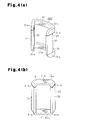
Fig. 4(a) is a perspective view showing an outer coil; -
Fig. 4(b) is a perspective view showing an inner coil; -
Fig. 5(a) is a perspective view showing a state where the outer coil is assembled into the stator core; -
Fig. 5(b) is a perspective view showing a state where the split teeth are attached between outer coils; -
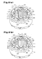
Fig. 6(a) is a perspective view showing a state where the inner coils are assembled; -
Fig. 6(b) is a perspective view showing a state where the split teeth are attached between the inner coils; -
Fig. 7 is a wiring diagram of the outer coils and the inner coils; and -
Fig. 8 is a schematic diagram showing a stator of a modification. - A stator of an electric machine according to one embodiment of the present invention will be described below with reference to
Figs. 1 to 7 . - As shown in
Fig. 2 , a rotational electric machine M as an electric machine includes astator 10 and arotor 15 as a movable element that is rotatably mounted inside of thestator 10. As shown inFigs. 1 and2 , thestator 10 includes anannular stator core 11, a plurality ofstationary teeth 12, and a plurality ofsplit teeth 13, which are arranged along a circumferential direction and radially inside thestator core 11, U-phase, V-phase and W-phaseouter coils inner coils stationary teeth 12 is twelve, the number of thesplit teeth 13 is twelve, and the number ofslots 14 is twenty-four24. Theslots 14 are arranged along a circumferential direction of thestator core 11 at equal pitch. - The
stator core 11 is configured by laminating a plurality of core plates made of magnetic material (steel plates) on one another in an axial direction. As shown inFigs. 2 and3(a) , the plurality ofstationary teeth 12 are integrally formed on an inner circumferential surface of thestator core 11. Thestationary teeth 12 extend radially inward of thestator core 11, i.e., in a first direction toward a center axis P of thestator core 11 from the inner circumferential surface of thestator core 11. Thestationary teeth 12 extend over the entire axial direction of thestator core 11. -
Engaging projections 11a are formed at intermediate locations betweenstationary teeth 12 that are adjacent to each other in the circumferential direction of thestator core 11 on the inner circumferential surface of thestator core 11 such that theengaging projections 11a extend over the entire axial direction of thestator core 11. Theengaging projections 11a are formed in a tapered shape such that their widths are gradually increased toward the center axis P (central portion) of thestator core 11 from the inner circumferential surface of thestator core 11. - As shown in
Figs. 1 and2 , thesplit teeth 13 are attached between thestationary teeth 12 that are adjacent to each other in the circumferential direction of thestator core 11, at positions radially inside thestator core 11. As shown inFig. 3(b) , each of thesplit teeth 13 has a rectangular plate shape and its longitudinal size (size along the axial direction of the stator core 11) is the same as the size of thestator core 11 in its axial direction. Anengaging recess 13c is formed on a proximal end surface of each of thesplit teeth 13 so as to extend over theentire split teeth 13 in its longitudinal direction. Theengaging recess 13c is formed in a tapered shape such that its width is gradually increased toward its distal end surface from the proximal end surface of thesplit tooth 13. - As shown in
Figs. 1 and2 , theengaging projections 11a of thestator core 11 are fitted into theengaging recesses 13c of thesplit teeth 13, thereby attaching thesplit teeth 13 to thestator core 11. In this attached state, theengaging projections 11a are engaged with theengaging recesses 13c, thereby preventing thesplit teeth 13 from moving radially inward of thestator core 11. Thesplit teeth 13 are attached to thestator core 11, thereby defining theslots 14 between thestationary teeth 12 and thesplit teeth 13 that are adjacent to each other in the circumferential direction of thestator core 11. Each of theslots 14 has a rectangular shape as viewed from above. - The U-phase, V-phase and W-phase
outer coils stationary teeth 12 in the distributed winding manner. There are pairs for the U-phase, V-phase and W-phaseouter coils outer coils stator core 11. Each of theouter coils stationary teeth 12 so as to extend across twoslots 14 and twostationary teeth 12 while sandwiching onesplit tooth 13 therebetween. Coils of different phases are not inserted into thesame slot 14. - The pair of
outer coils 30U is disposed at an angular distance of 180° from each other, and is inserted into a total of fourslots 14. Eightslots 14 exist between aslot 14 into which one of theouter coils 30U is inserted and aslot 14 into which the otherouter coil 30U is inserted. Theouter coils 30V and theouter coils 30W are disposed also in the same manner. Theouter coils Fig. 4(a) , each of theouter coils outer coil 30U is shown inFig. 4(a) ) includes a pair of insertingportions 37 inserted into theslots 14, and a pair of coil ends 31 (first coil ends) protruding from both end surfaces of thestator core 11 in its axial direction. - As shown in
Figs. 1 and2 , thecoil end 31 of each of theouter coils bent portions 31a, which are bent so as to extend radially outward of the stator core 11 (second direction opposite to the first direction) from the insertingportions 37. Further, each of the outer coil ends 31 includes anouter bridge portion 31b, which extends along the circumferential direction of thestator core 11 so as to connect distal ends of the pair ofbent portions 31a with each other. Each of the outer coil ends 31 is formed by the pair ofbent portions 31a and theouter bridge portions 31b into a channel shape as viewed from above. In each of theouter coils outer bridge portions 31b are formed into predetermined shapes so as to extend along the circumferential direction of thestator core 11. Theouter bridge portion 31b is disposed radially outside the inner circumferential surface (this corresponds to a bottom of the slot 14) of thestator core 11 in thestator core 11. When the insertingportion 37 is assembled into theslots 14, portions that protrude outward from both end surfaces of thestator core 11 in the axial direction are the outer coil ends 31. As shown inFig. 4(a) , aninsulation sheet 32 made of synthetic resin is wound around each of the insertingportions 37. - The U-phase, V-phase and W-phase
inner coils stationary teeth 12 in the distributed winding manner. There are pairs ofinner coils inner coils stator core 11. Each of theinner coils stationary teeth 12 so as to extend across twoslots 14 and twostationary teeth 12 that sandwich onesplit tooth 13 therebetween. Coils of different phases are not inserted into thesame slot 14. - The pair of
inner coils 40U is disposed at an angular distance of 180° from each other, and is inserted into a total of fourslots 14. Theinner coils 40V and theinner coils 40W are disposed also in the same manner. Theinner coils Fig. 4(b) , each of theinner coils inner coil 40U is shown inFig. 4(b) ) includes a pair of insertingportions 47 inserted into theslots 14, and a pair of coil ends 41 (second coil ends) protruding from both end surfaces of thestator core 11 in its axial direction. - As shown in
Figs. 1 and2 , the coil end 41 (hereinafter, referred to as an inner coil end 41) of each of theinner coils upright portions 41a extending from the insertingportions 47 along the axial direction of thestator core 11. Theinner coil end 41 further includes aninner bridge portion 41b extending along the circumferential direction of thestator core 11 so as to connect distal ends of the pair ofupright portions 41a with each other. Each of the inner coil ends 41 is formed by the pair ofupright portions 41a and the pair ofinner bridge portions 41b into a channel shape as viewed from the front. As shown inFig. 4(b) , aninsulation sheet 32 made of synthetic resin is wound around each of the insertingportions 47. - In a state where the
outer coils inner coils slots 14, theouter bridge portions 31b are disposed outside theinner bridge portions 41b in the radial direction of thestator core 11. In other words, theouter bridge portions 31b are disposed on the opposite side from therotor 15 with respect to theinner bridge portions 41b. Theouter bridge portions 31b are disposed on a first circumference around the center axis P of thestator core 11, and theinner bridge portions 41b are disposed on a second circumference located radially inside the first circumference. The insertingportions inner bridge portions 41b extends across thebent portions 31a of twoouter coils 30U that are adjacent to each other in the circumferential direction of thestator core 11. In a state where theinner coils slots 14, teeth that are adjacent to theupright portions 41a between the pair ofupright portions 41a of each of the inner coil ends 41 are thestationary teeth 12. Teeth sandwiched between theouter bridge portion 31b and theinner bridge portion 41b that partially overlaps theouter bridge portion 31b in the circumferential direction are thestationary teeth 12. Theouter coils stator core 11 prior to theinner coils - Next, a producing method of the
stator 10 will be described. - First, in a state where the
split teeth 13 are detached from thestator core 11, as shown inFig. 5(a) , each of theouter coils stationary teeth 12 that sandwich one engagingprojection 11a. That is, each of theouter coils stator core 11. Each of theouter coils stationary teeth 12 such that the pair ofstationary teeth 12 is disposed inside theouter coils outer coils stator core 11. - In this assembled state, gaps into which split
teeth 13 can be inserted are formed between the U-phaseouter coil 30U and the V-phaseouter coil 30V that are adjacent to each other in the circumferential direction, between the V-phaseouter coil 30V and the W-phaseouter coil 30W that are adjacent to each other in the circumferential direction, and between the W-phaseouter coil 30W and the U-phaseouter coil 30U that are adjacent to each other in the circumferential direction. - Next, as shown in
Fig. 5(b) , thesplit teeth 13 are inserted into gaps each formed between two of theouter coils stator core 11, and thesplit teeth 13 are attached to thestator core 11. While moving thesplit teeth 13 along the axial direction of thestator core 11, the engagingrecesses 13c of thesplit teeth 13 are fitted to the engagingprojections 11a of thestator core 11, thereby attaching thesplit teeth 13 to thestator core 11. - Then, the
slots 14 are defined between thestationary teeth 12 and thesplit teeth 13 that are adjacent to each other in the circumferential direction of thestator core 11. The insertingportions 37 of theouter coils slots 14. - In a state where the
outer coils stator core 11, thebent portions 31a of the outer coil ends 31 extend from the inserting portions 37 (the slots 14) radially outward of thestator core 11. Hence, gaps are formed between thebent portions 31a of the outer coil ends 31 that are adjacent to each other in the circumferential direction, and the engagingprojections 11a are opened in the axial direction of thestator core 11 in the gaps. That is, thebent portions 31a do not exist on extensions of the engagingprojections 11a along the axial direction of thestator core 11. Hence, it is possible to insert thesplit teeth 13 between the twobent portions 31a that exist between the pair ofstationary teeth 12 while moving thesplit teeth 13 along the axial direction of thestator core 11. - Next, as shown in
Fig. 6(a) , each of theinner coils stationary teeth 12 that sandwich onesplit tooth 13. That is, each of theinner coils stationary tooth 12 across which theinner bridge portion 41b and theouter bridge portion 31b extend. - Each of the
inner coils stator core 11 from an inner space of thestator core 11, and each of theinner coils stationary teeth 12 such that the same pair of stationary teeth 12 (and onesplit tooth 13 between the same pair of stationary teeth 12) are disposed inside theinner coils outer bridge portion 31b is disposed radially outside the inner circumferential surface (this corresponds to the bottom of the slot 14) of thestator core 11, and a gap is formed between the pair ofbent portions 31a on both ends of theouter bridge portion 31b. Hence, theouter bridge portions 31b do not hinder assembling of theinner coils inner coils portions 37 are accommodated in the gaps between thestationary teeth 12; and each of theinner bridge portions 41b extends across twobent portions 31a, which are adjacent to each other in the circumferential direction of thestator core 11, and is disposed radially inside theouter bridge portion 31b. - The pairs of U-phase, V-phase and W-phase
inner coils stationary teeth 12 such that theinner coils split teeth 13 can be inserted are formed between the U-phaseinner coil 40U and the V-phaseinner coil 40V that are adjacent to each other in the circumferential direction, between the V-phaseinner coil 40V and the W-phaseinner coil 40W that are adjacent to each other in the circumferential direction, and between the W-phaseinner coil 40W and the U-phaseinner coil 40U that are adjacent to each other in the circumferential direction. - Next, as shown in
Fig. 6(b) , thesplit teeth 13 are inserted into gaps between two of theinner coils stator core 11, and thesplit teeth 13 are attached to thestator core 11. Theouter bridge portions 31b are disposed radially outside the inner circumferential surface of thestator core 11, and are disposed radially outside the engagingprojections 11a of thestator core 11. Gaps that are opened in the axial direction of thestator core 11 are formed between the twobent portions 31a disposed between thestationary teeth 12 that are adjacent to each other in the circumferential direction. Hence, theouter bridge portions 31b and thebent portions 31a do not hinder the insertion of thesplit teeth 13. - The
split teeth 13 are attached to thestator core 11 such that thesplit teeth 13 and thestationary teeth 12 sandwich the insertingportions 47 of theinner coils split teeth 13 are fitted to the engagingprojections 11a of thestator core 11 while moving thesplit teeth 13 along the axial direction of thestator core 11, thereby attaching thesplit teeth 13 to thestator core 11. - When the
split teeth 13 are attached to thestator core 11, theslots 14 are defined between thestationary teeth 12 and thesplit teeth 13 that are adjacent to each other in the circumferential direction. The insertingportions 47 of theinner coils slots 14. -
Fig. 7 is a wiring diagram of theouter coils inner coils stator 10 produced by the above-described method. U-phase inserting portions (shown with 37U inFig. 7 only) of a pair ofouter coils 30U that are connected to aU-phase terminal 51 of aninverter 50 pass through a group of the U-phase slots (shown with 14Uo inFig. 7 only). V-phase inserting portions (shown with 37V inFig. 7 only) of a pair ofouter coils 30V that are connected to a V-phase terminal 52 of theinverter 50 pass through a group of the V-phase slots (shown with 14Vo inFig. 7 only). W-phase inserting portions (shown with 37W inFig. 7 only) of a pair ofouter coils 30W that are connected to a W-phase terminal 53 of theinverter 50 pass through a group of the W-phase slots (shown with 14Wo inFig. 7 only). - U-phase inserting portions (shown with 47U in
Fig. 7 only) of a pair ofinner coils 40U that are connected to theU-phase terminal 51 of theinverter 50 pass through a group of the U-phase slots (shown with 14Ui inFig. 7 only). V-phase inserting portions (shown with 47V inFig. 7 only) of a pair ofinner coils 40V that are connected to the V-phase terminal 52 of theinverter 50 pass through a group of the V-phase slots (shown with 14Vi inFig. 7 only). W-phase inserting portions (shown with 47W inFig. 7 only) of a pair ofinner coils 40W that are connected to the W-phase terminal 53 of theinverter 50 pass through a group of the W-phase slots (shown with 14Wi inFig. 7 only). - The U-phase
outer coil 30U and the U-phaseinner coil 40U are connected to each other in series. As the U-phase coils, the same number of first series ofouter coils 30U and second series ofinner coils 40U are used (two each). The V-phaseouter coil 30V and the V-phaseinner coil 40V are connected to each other in series. As the V-phase coils, the same number of first series ofouter coils 30V and second series ofinner coils 40V are used (two each). The W-phaseouter coil 30W and the W-phaseinner coil 40W are connected to each other in series. As the W-phase coils, the same number of first series ofouter coils 30W and second series ofinner coils 40W are used (two each). - A symbol N1 represents a neutral point that connects terminal ends of
coil wires outer coils inner coils coil wires outer coils inner coils rotor 15 is rotated by energizing theouter coils inner coils inverter 50. - This embodiment has the following merits.
- (1) Preformed U-phase, V-phase and W-phase
outer coils inner coils outer coils outer bridge portions 31b are disposed radially outside theinner bridge portions 41b of theinner coils inner coils stationary teeth 12 after theouter coils stationary teeth 12, the coil ends 31 and 41 do not interfere with each other. Hence, even though the rotational electric machine has the coils of three phases, it is only necessary to form two kinds of coils, i.e., theouter coils inner coils stator 10 can be reduced as compared with a case where the coils of three phases are formed into different shapes. - (2) The
outer bridge portions 31b (outer coil ends 31) of the U-phase, V-phase and W-phaseouter coils stator core 11, and theouter coils inner bridge portions 41b (inner coil ends 41) of the U-phase, V-phase and W-phaseinner coils stator core 11, and theinner coils - (3) As the coil ends, only two kinds of coil ends, i.e., the outer coil ends 31 and the inner coil ends 41 exist. Therefore, it is possible to reduce the lengths of the
outer coil end 31 and theinner coil end 41 protruding from the end surface of thestator core 11 as compared with a case where the coil ends of coils of the three phases are formed into different shapes so that the coil ends do not interfere with each other. - (4) The U-phase
outer coil 30U and the U-phaseinner coil 40U are connected to each other in series, the V-phaseouter coil 30V and the V-phaseinner coil 40V are connected to each other in series, and the W-phaseouter coil 30W and the W-phaseinner coil 40W are connected to each other in series. The pairs ofouter coils inner coils - (5) The
outer coils inner coils outer coils inner coils - (6) The
stator 10 includes thestationary teeth 12, which are integrally formed on thestator core 11, and thesplit teeth 13, which can be attached to and detached from thestator core 11. After theouter coils stationary teeth 12, some of thesplit teeth 12 are attached to thestator core 11, thereby defining theslots 14. After theinner coils stationary teeth 12, remaining splitteeth 13 are attached to thestator core 11, thereby defining theslots 14. Therefore, even when thestator 10 of the distributed winding type is produced, it is unnecessary to deform the coils when assembling theouter coils inner coils slots 14. Also, it is possible to prevent the coil wires from being damaged, and it is possible to prevent performance of the rotational electric machine M from being deteriorated when thestator 10 is produced. - (7) Among all of the teeth, half of them are the
stationary teeth 12. Therefore, as compared with a case where all of the teeth are thesplit teeth 13, it is possible to shorten time required for attaching all of the teeth to thestator core 11, to reduce the number of parts, and to reduce the production costs of thestator 10. Further, as compared with the case where all of the teeth are thesplit teeth 13, it is possible to reduce iron loss generated by gaps of the fitted portions of thesplit teeth 13 and thestator core 11, and to reduce variation in gaps between teeth that are adjacent to each other in the circumferential direction of thestator core 11. As a result, it is possible to prevent torque ripple from increasing. In addition, when all of the teeth are made as thesplit teeth 13, a plastic deformation amount generated when all of thesplit teeth 13 are attached to thestator core 11 is increased. In the case of this embodiment, however, only half of all of the teeth are thesplit teeth 13, it is possible to reduce the plastic deformation amount caused when thesplit teeth 13 are assembled, and to reduce the deterioration in electromagnetic characteristics. - The above-described embodiment may be modified as follows.
- If the first series of
outer coils outer bridge portions 31b are disposed radially outside (opposite side to the protruding direction of the stationary teeth 12) of theinner bridge portions 41b, theouter coils inner coils inner bridge portions 41b extend across thebent portion 31a, and the lengths or the like of the coil wires may be different from one phase to another. In this case, it is preferable that only the shapes of the insertingportions 37 of theouter coils portions 47 of theinner coils - The first series of coils may be configured so that the series include a mixture of coils of at least two phases (U-phase and V-phase, V-phase and W-phase, or W-phase and U-phase), and the second series of coils may be configured so that the series include a mixture of coils of at least two phases (V-phase and W-phase, W-phase and U-phase, or U-phase and V-phase)
- The combination between the number of poles and the number of slots may appropriately be changed if "the number of poles × the number of phases (3) = the number of slots". If the number of poles is "6", the number of slots will be eighteen since the number of phases is "3". Alternatively, the number of poles and the number of slots may appropriately be changed if "the number of poles × the number of phases (3) × the number of coils in one series = the number of slots". For example, as shown in
Fig. 8 , when the number of poles is "8" and the number of phases is "3" and there are two kinds of coils in each of the first series and the second series, the number of slots will be forty eight. InFig. 8 , the first series of coils are firstouter coils outer coils outer coils stator core 11. Further, second series of coils are firstinner coils inner coils inner coils stator core 11. - All of the teeth may be the
stationary teeth 12 or all of the teeth may be thesplit teeth 13. - As the electric machine, a stator of a straight type electric machine such as a linear motor may be formed as in the present invention. In the straight type electric machine, an outer coil (first series of coil) means a coil that is assembled into a stator core prior to an inner coil (second series of coil) and its bridge portion is disposed on a side opposite to a protruding direction of teeth as compared with a bridge portion of the inner coil, and an inner coil means a coil that is assembled into the stator core after the outer coil, and its bridge portion is disposed on a side of the protruding direction of the teeth as compared with the bridge portion of the outer coil.
- M...Rotational Electric Machine as Electric Machine, 10...Stator, 11...Stator Core, 12...Stationary Tooth as Tooth, 13...Split Tooth as Tooth, 14...Slot, 30u, 30v, 30w, 301 u, 301v, 301w, 302u, 302v, 302w...Outer Coil as First Series of Coil, 31...Outer Coil End as First Series of Coil End, 31a...Bent Portion, 31b...Outer Bridge Portion, 37...Inserting Portion of Outer Coil, 40u, 40v, 40w, 401 u, 401v, 401w, 402u, 402v, 402w...Inner Coil as Second Series of Coil, 41 ...Inner Coil End as Second Series Coil End, 41a...Upright Portion, 41b...lnner Bridge Portion, 47...Inserting Portion of Inner Coil
Claims (9)
- A stator for an electric machine, the stator comprising:a stator core;a plurality of teeth that extend into a first direction from the stator core and are arranged such that a slot is formed between adjacent teeth;a first series of coils that are assembled into the slots and are formed into predetermined shapes; anda second series of coils that are assembled into the slots and are formed into predetermined shapes, whereineach of the first series of coils includes a pair of inserting portions respectively inserted into the slots, and a pair of first coil ends protruding from both end surfaces of the stator core, each of the first coil ends including a pair of bent portions extending from ends of the pair of inserting portions into a second direction that is opposite to the first direction, and a bridge portion that connects the bent portions with each other,each of the second series of coils includes a pair of inserting portions respectively inserted into the slots, and second coil ends protruding from both end surfaces of the stator core, each of the second coil ends including a pair of upright portions extending from ends of the pair of inserting portions, and a bridge portion that connects the upright portions with each other,the bridge portions of the first series of coils are disposed on the side toward the second direction with respect to the bridge portions of the second series of coils, the bridge portions of the second series of coils each extend across the bent portions of two adjacent first series of coils, andthe first series of coils and the second series of coils are configured so that each series includes a mixture of coils of at least two phases among a U-phase, a V-phase and a W-phase, and each of the coils in the first series is connected to a coil of the same phase in the second series.
- The stator according to claim 1, wherein
each coil in each phase in the first series is connected in series to a coil of the same phase in the second series, and
the number of coils of each phase in the first series is the same as the number of coils in the same phase in the second series. - The stator according to claim 1 or 2, wherein all of the first series of coils have the same shapes, and all of the second series of coils have the same shapes.
- The stator according to any one of claims 1 to 3, wherein the teeth include stationary teeth, which are integrally formed on the stator core, and split teeth, which can be attached to the stator core.
- The stator according to claim 4, wherein half of all of the teeth are stationary teeth.
- The stator according to any one of claims 1 to 5, wherein the bridge portions of the first series of coils are disposed on the side toward the second direction with respect to the slots.
- The stator according to any one of claims 1 to 6, wherein
the stator core is cylindrical in shape,
the teeth are arranged along a circumferential direction of the stator core,
the teeth extend from an inner circumferential surface of the stator core into the first direction, and
the bridge portions of the first series of coils are disposed on the side toward the second direction of the stator core with respect to the slots. - The stator according to claim 7, wherein
the bridge portions of the first series of coils are disposed on a first circumference formed around a center axis of the stator core, and
the bridge portions of the second series of coils are disposed on a second circumference that is on the side toward the first direction with respect to the first circumference. - The stator according to claim 8, wherein the inserting portions of the first series of coils and the inserting portion of the second series of coils are disposed on the second circumference.
Applications Claiming Priority (2)
| Application Number | Priority Date | Filing Date | Title |
|---|---|---|---|
| JP2009095158A JP5446406B2 (en) | 2009-04-09 | 2009-04-09 | Stator in electric machine |
| PCT/JP2010/055736 WO2010116928A1 (en) | 2009-04-09 | 2010-03-30 | Stator for electric machine |
Publications (2)
| Publication Number | Publication Date |
|---|---|
| EP2418757A1 true EP2418757A1 (en) | 2012-02-15 |
| EP2418757A4 EP2418757A4 (en) | 2016-02-24 |
Family
ID=42936213
Family Applications (1)
| Application Number | Title | Priority Date | Filing Date |
|---|---|---|---|
| EP10761627.8A Withdrawn EP2418757A4 (en) | 2009-04-09 | 2010-03-30 | Stator for electric machine |
Country Status (6)
| Country | Link |
|---|---|
| US (1) | US8704420B2 (en) |
| EP (1) | EP2418757A4 (en) |
| JP (1) | JP5446406B2 (en) |
| KR (1) | KR101237250B1 (en) |
| CN (1) | CN102369651B (en) |
| WO (1) | WO2010116928A1 (en) |
Families Citing this family (16)
| Publication number | Priority date | Publication date | Assignee | Title |
|---|---|---|---|---|
| JP2013062897A (en) * | 2011-09-12 | 2013-04-04 | Aida Engineering Ltd | Inverter motor device |
| JP5910738B2 (en) * | 2012-06-01 | 2016-04-27 | 株式会社安川電機 | Rotating electric machine, rotating electric stator and vehicle |
| CN104380574B (en) * | 2012-06-01 | 2016-11-16 | 株式会社安川电机 | Electric rotating machine, stator for electric rotating machine and vehicle |
| JP6356394B2 (en) | 2013-08-07 | 2018-07-11 | 株式会社東芝 | Rotating electric machine and method of manufacturing rotating electric machine |
| US9906105B1 (en) * | 2014-01-28 | 2018-02-27 | Maestra Energy, Llc | Electrical induction motor with reconfigured rotor mounted commutators for receiving an armature current from a stator mounted brush component along with a reversing gear arrangement for driving a pair of opposite gear rings |
| JP6248704B2 (en) * | 2014-03-03 | 2017-12-20 | 株式会社豊田自動織機 | In-vehicle electric compressor |
| DE102015225586A1 (en) * | 2015-12-17 | 2017-06-22 | Volkswagen Aktiengesellschaft | Bobbin for an electric coil |
| JP2017131046A (en) * | 2016-01-21 | 2017-07-27 | 株式会社明電舎 | Coil and stator of rotary electric machine using the same |
| JP6682956B2 (en) * | 2016-03-30 | 2020-04-15 | アイシン精機株式会社 | MOTOR DEVICE AND METHOD OF MANUFACTURING MOTOR DEVICE |
| CN105790479A (en) * | 2016-04-05 | 2016-07-20 | 中国船舶重工集团公司第七〇二研究所 | Ship propulsion motor and stator coil winding method thereof |
| DE102017102314A1 (en) * | 2017-02-07 | 2018-08-09 | SciMo - Elektrische Hochleistungsantriebe GmbH | Winding of an electric machine with increased degree of filling |
| JP7348029B2 (en) * | 2019-10-31 | 2023-09-20 | ファナック株式会社 | stator and motor |
| JP7342654B2 (en) * | 2019-11-26 | 2023-09-12 | 株式会社デンソー | rotating electric machine |
| JP7621862B2 (en) * | 2021-03-31 | 2025-01-27 | ミネベアミツミ株式会社 | Motor |
| JP7735694B2 (en) * | 2021-06-18 | 2025-09-09 | 株式会社デンソー | Motor |
| WO2024087813A1 (en) * | 2022-10-27 | 2024-05-02 | 安徽威灵汽车部件有限公司 | Stator, electric motor and vehicle |
Family Cites Families (22)
| Publication number | Priority date | Publication date | Assignee | Title |
|---|---|---|---|---|
| US3495114A (en) * | 1968-06-14 | 1970-02-10 | Vasily Mikhailovich Kz | Cylindrical and disc stators for electrical machines having composite windings |
| JPH06261475A (en) * | 1993-03-08 | 1994-09-16 | Honda Motor Co Ltd | Core of motor of generator |
| JP3484006B2 (en) * | 1996-01-30 | 2004-01-06 | 株式会社日立製作所 | Rotating machine and molding method |
| JPH10146030A (en) * | 1996-11-05 | 1998-05-29 | Hitachi Ltd | Rotating electric machine with concentrated winding stator |
| JP3514939B2 (en) | 1997-03-27 | 2004-04-05 | 株式会社日立製作所 | Method for manufacturing electric motor and stator |
| US6229241B1 (en) * | 1997-03-26 | 2001-05-08 | Hitachi, Ltd. | Structure and manufacturing method for motor and stator |
| JP2002125340A (en) * | 1998-02-03 | 2002-04-26 | Hitachi Ltd | Motor, manufacturing method thereof and inserter used for the same |
| AU6773300A (en) | 1999-08-16 | 2001-03-13 | American Superconductor Corporation | Water cooled stator winding of an electric motor |
| US7211919B2 (en) | 1999-08-16 | 2007-05-01 | American Superconductor Corporation | Thermally-conductive stator support structure |
| JP2005124362A (en) * | 2003-10-20 | 2005-05-12 | Toyota Industries Corp | Winding cable and armature |
| JP2005348461A (en) * | 2004-05-31 | 2005-12-15 | Asahi Denki Kenkyusho:Kk | Aligned winding coil and method of forming aligned winding coil |
| US7247967B2 (en) * | 2004-08-09 | 2007-07-24 | A. O. Smith Corporation | Electric motor having a stator |
| JP4431116B2 (en) * | 2005-01-28 | 2010-03-10 | 株式会社モステック | Coil, coil unit, stator and rotor, coil and coil unit manufacturing jig, and coil and coil unit manufacturing method |
| JP4678522B2 (en) * | 2006-03-31 | 2011-04-27 | アイシン・エィ・ダブリュ株式会社 | Stator and rotating electric machine |
| JP2007329985A (en) * | 2006-06-06 | 2007-12-20 | Daikin Ind Ltd | Axial gap type motor and manufacturing method thereof |
| JP5253789B2 (en) * | 2007-11-05 | 2013-07-31 | 株式会社ミツバ | Brushless motor |
| JP5354888B2 (en) * | 2007-11-05 | 2013-11-27 | 株式会社ミツバ | Brushless motor |
| JP2009189078A (en) * | 2008-02-01 | 2009-08-20 | Toyota Industries Corp | Stator of rotary electric machine, and rotary electric machine |
| EP2112747B1 (en) * | 2008-04-24 | 2014-01-22 | Magneti Marelli S.p.A. | Electrical machine and method for manufacturing the same |
| JP5235634B2 (en) * | 2008-12-05 | 2013-07-10 | 日立オートモティブシステムズ株式会社 | Manufacturing method of rotating electrical machine |
| EP2226923B1 (en) * | 2009-03-03 | 2015-06-10 | GE Energy Power Conversion Technology Limited | Coils |
| DE102009032883A1 (en) * | 2009-07-13 | 2011-01-27 | Siemens Aktiengesellschaft | Winding arrangement |
-
2009
- 2009-04-09 JP JP2009095158A patent/JP5446406B2/en not_active Expired - Fee Related
-
2010
- 2010-03-30 EP EP10761627.8A patent/EP2418757A4/en not_active Withdrawn
- 2010-03-30 CN CN201080014398.4A patent/CN102369651B/en not_active Expired - Fee Related
- 2010-03-30 US US13/256,679 patent/US8704420B2/en not_active Expired - Fee Related
- 2010-03-30 WO PCT/JP2010/055736 patent/WO2010116928A1/en not_active Ceased
- 2010-03-30 KR KR1020117020859A patent/KR101237250B1/en not_active Expired - Fee Related
Non-Patent Citations (1)
| Title |
|---|
| See references of WO2010116928A1 * |
Also Published As
| Publication number | Publication date |
|---|---|
| JP2010246343A (en) | 2010-10-28 |
| CN102369651B (en) | 2014-06-18 |
| KR101237250B1 (en) | 2013-02-27 |
| EP2418757A4 (en) | 2016-02-24 |
| CN102369651A (en) | 2012-03-07 |
| KR20110125233A (en) | 2011-11-18 |
| US8704420B2 (en) | 2014-04-22 |
| US20120001513A1 (en) | 2012-01-05 |
| WO2010116928A1 (en) | 2010-10-14 |
| JP5446406B2 (en) | 2014-03-19 |
Similar Documents
| Publication | Publication Date | Title |
|---|---|---|
| US8704420B2 (en) | Stator for electric machine | |
| US8384263B2 (en) | Rotating electrical machine having a compact stator | |
| EP2840692B1 (en) | Spoke permanent magnet machine with reduced torque ripple and method of manufacturing thereof | |
| EP2273654B1 (en) | Rotating electric machine and manufacturing method thereof | |
| EP1971014B1 (en) | Armature laminations | |
| JP2010200596A (en) | Armature for rotating electrical machine and manufacturing method of same | |
| KR20120041127A (en) | Stator, brushless motor, and manufacturing method of the same | |
| US7915780B2 (en) | Laminated spiral core, dynamo-electric-machine rotor provided therewith, and dynamo-electric machine | |
| JP5619046B2 (en) | Rotating electric machine and method of manufacturing stator used therefor | |
| CN102130521A (en) | Rotating electric machine and method for manufacturing stator of rotating electric machine | |
| JP2010239740A (en) | Armature for rotating electric machine | |
| CN109923756B (en) | Rotary motor | |
| CN108736614B (en) | Stator of rotating electric machine | |
| JP2013128366A (en) | Helically wound sheet-like coils, fixing method thereof and motor coils | |
| JP2010239739A (en) | Interphase insulation sheet | |
| JP2004080944A (en) | Stator core for electric motor | |
| JP2012095488A (en) | Rotor for rotary electric machine and rotary electric machine using the same | |
| CN104380574A (en) | Rotating electric machine, stator for rotating electric machine, and vehicle | |
| JP2015057012A (en) | Rotating electric machine | |
| JP5298798B2 (en) | motor | |
| JP2010246342A (en) | Stator in electric machine | |
| JP2011160572A (en) | Method for manufacturing stator of rotary electric machine | |
| CN212033857U (en) | Motor stator and motor | |
| JP2002325382A (en) | Method for manufacturing rotating electric machine and rotating electric machine | |
| CN115347691A (en) | Motor stator and motor |
Legal Events
| Date | Code | Title | Description |
|---|---|---|---|
| PUAI | Public reference made under article 153(3) epc to a published international application that has entered the european phase |
Free format text: ORIGINAL CODE: 0009012 |
|
| 17P | Request for examination filed |
Effective date: 20111005 |
|
| AK | Designated contracting states |
Kind code of ref document: A1 Designated state(s): AT BE BG CH CY CZ DE DK EE ES FI FR GB GR HR HU IE IS IT LI LT LU LV MC MK MT NL NO PL PT RO SE SI SK SM TR |
|
| DAX | Request for extension of the european patent (deleted) | ||
| RA4 | Supplementary search report drawn up and despatched (corrected) |
Effective date: 20160127 |
|
| RIC1 | Information provided on ipc code assigned before grant |
Ipc: H02K 1/18 20060101ALI20160120BHEP Ipc: H02K 3/04 20060101AFI20160120BHEP |
|
| STAA | Information on the status of an ep patent application or granted ep patent |
Free format text: STATUS: THE APPLICATION IS DEEMED TO BE WITHDRAWN |
|
| 18D | Application deemed to be withdrawn |
Effective date: 20160823 |