EP2418465B1 - Profilage d'amplitude dans des appareils de mesure du niveau de remplissage - Google Patents
Profilage d'amplitude dans des appareils de mesure du niveau de remplissage Download PDFInfo
- Publication number
- EP2418465B1 EP2418465B1 EP10170031.8A EP10170031A EP2418465B1 EP 2418465 B1 EP2418465 B1 EP 2418465B1 EP 10170031 A EP10170031 A EP 10170031A EP 2418465 B1 EP2418465 B1 EP 2418465B1
- Authority
- EP
- European Patent Office
- Prior art keywords
- amplitude
- echo
- level
- filling
- measuring device
- Prior art date
- Legal status (The legal status is an assumption and is not a legal conclusion. Google has not performed a legal analysis and makes no representation as to the accuracy of the status listed.)
- Active
Links
- 238000000034 method Methods 0.000 claims description 62
- 238000002592 echocardiography Methods 0.000 claims description 35
- 239000000463 material Substances 0.000 claims description 13
- 230000005540 biological transmission Effects 0.000 claims description 6
- 238000005259 measurement Methods 0.000 description 24
- 238000011156 evaluation Methods 0.000 description 13
- 238000012545 processing Methods 0.000 description 13
- 230000006870 function Effects 0.000 description 11
- 230000033001 locomotion Effects 0.000 description 11
- 238000000605 extraction Methods 0.000 description 7
- 239000007788 liquid Substances 0.000 description 5
- 238000004364 calculation method Methods 0.000 description 4
- 230000008859 change Effects 0.000 description 4
- 238000001514 detection method Methods 0.000 description 4
- 230000007340 echolocation Effects 0.000 description 4
- 230000007547 defect Effects 0.000 description 3
- 238000009434 installation Methods 0.000 description 3
- 238000012544 monitoring process Methods 0.000 description 3
- 238000002604 ultrasonography Methods 0.000 description 3
- 230000006978 adaptation Effects 0.000 description 2
- 230000008901 benefit Effects 0.000 description 2
- 230000008569 process Effects 0.000 description 2
- 102000010292 Peptide Elongation Factor 1 Human genes 0.000 description 1
- 108010077524 Peptide Elongation Factor 1 Proteins 0.000 description 1
- 206010038743 Restlessness Diseases 0.000 description 1
- 230000009471 action Effects 0.000 description 1
- 230000002238 attenuated effect Effects 0.000 description 1
- 230000015572 biosynthetic process Effects 0.000 description 1
- 230000000903 blocking effect Effects 0.000 description 1
- 239000013590 bulk material Substances 0.000 description 1
- 230000006835 compression Effects 0.000 description 1
- 238000007906 compression Methods 0.000 description 1
- 238000010276 construction Methods 0.000 description 1
- 238000012937 correction Methods 0.000 description 1
- 230000001419 dependent effect Effects 0.000 description 1
- 238000011161 development Methods 0.000 description 1
- 230000018109 developmental process Effects 0.000 description 1
- 239000000428 dust Substances 0.000 description 1
- 230000000694 effects Effects 0.000 description 1
- 238000013213 extrapolation Methods 0.000 description 1
- 239000006260 foam Substances 0.000 description 1
- 238000000691 measurement method Methods 0.000 description 1
- 230000007246 mechanism Effects 0.000 description 1
- 238000005293 physical law Methods 0.000 description 1
- 238000002310 reflectometry Methods 0.000 description 1
- 238000004088 simulation Methods 0.000 description 1
- 239000007787 solid Substances 0.000 description 1
- 230000001502 supplementing effect Effects 0.000 description 1
- 230000007704 transition Effects 0.000 description 1
Images


Classifications
-
- G—PHYSICS
- G01—MEASURING; TESTING
- G01S—RADIO DIRECTION-FINDING; RADIO NAVIGATION; DETERMINING DISTANCE OR VELOCITY BY USE OF RADIO WAVES; LOCATING OR PRESENCE-DETECTING BY USE OF THE REFLECTION OR RERADIATION OF RADIO WAVES; ANALOGOUS ARRANGEMENTS USING OTHER WAVES
- G01S13/00—Systems using the reflection or reradiation of radio waves, e.g. radar systems; Analogous systems using reflection or reradiation of waves whose nature or wavelength is irrelevant or unspecified
- G01S13/02—Systems using reflection of radio waves, e.g. primary radar systems; Analogous systems
- G01S13/06—Systems determining position data of a target
- G01S13/08—Systems for measuring distance only
-
- G—PHYSICS
- G01—MEASURING; TESTING
- G01F—MEASURING VOLUME, VOLUME FLOW, MASS FLOW OR LIQUID LEVEL; METERING BY VOLUME
- G01F23/00—Indicating or measuring liquid level or level of fluent solid material, e.g. indicating in terms of volume or indicating by means of an alarm
- G01F23/22—Indicating or measuring liquid level or level of fluent solid material, e.g. indicating in terms of volume or indicating by means of an alarm by measuring physical variables, other than linear dimensions, pressure or weight, dependent on the level to be measured, e.g. by difference of heat transfer of steam or water
- G01F23/28—Indicating or measuring liquid level or level of fluent solid material, e.g. indicating in terms of volume or indicating by means of an alarm by measuring physical variables, other than linear dimensions, pressure or weight, dependent on the level to be measured, e.g. by difference of heat transfer of steam or water by measuring the variations of parameters of electromagnetic or acoustic waves applied directly to the liquid or fluent solid material
- G01F23/284—Electromagnetic waves
-
- G—PHYSICS
- G01—MEASURING; TESTING
- G01F—MEASURING VOLUME, VOLUME FLOW, MASS FLOW OR LIQUID LEVEL; METERING BY VOLUME
- G01F23/00—Indicating or measuring liquid level or level of fluent solid material, e.g. indicating in terms of volume or indicating by means of an alarm
- G01F23/22—Indicating or measuring liquid level or level of fluent solid material, e.g. indicating in terms of volume or indicating by means of an alarm by measuring physical variables, other than linear dimensions, pressure or weight, dependent on the level to be measured, e.g. by difference of heat transfer of steam or water
- G01F23/28—Indicating or measuring liquid level or level of fluent solid material, e.g. indicating in terms of volume or indicating by means of an alarm by measuring physical variables, other than linear dimensions, pressure or weight, dependent on the level to be measured, e.g. by difference of heat transfer of steam or water by measuring the variations of parameters of electromagnetic or acoustic waves applied directly to the liquid or fluent solid material
- G01F23/296—Acoustic waves
-
- G—PHYSICS
- G01—MEASURING; TESTING
- G01F—MEASURING VOLUME, VOLUME FLOW, MASS FLOW OR LIQUID LEVEL; METERING BY VOLUME
- G01F25/00—Testing or calibration of apparatus for measuring volume, volume flow or liquid level or for metering by volume
- G01F25/20—Testing or calibration of apparatus for measuring volume, volume flow or liquid level or for metering by volume of apparatus for measuring liquid level
-
- G—PHYSICS
- G01—MEASURING; TESTING
- G01S—RADIO DIRECTION-FINDING; RADIO NAVIGATION; DETERMINING DISTANCE OR VELOCITY BY USE OF RADIO WAVES; LOCATING OR PRESENCE-DETECTING BY USE OF THE REFLECTION OR RERADIATION OF RADIO WAVES; ANALOGOUS ARRANGEMENTS USING OTHER WAVES
- G01S13/00—Systems using the reflection or reradiation of radio waves, e.g. radar systems; Analogous systems using reflection or reradiation of waves whose nature or wavelength is irrelevant or unspecified
- G01S13/88—Radar or analogous systems specially adapted for specific applications
-
- G—PHYSICS
- G01—MEASURING; TESTING
- G01S—RADIO DIRECTION-FINDING; RADIO NAVIGATION; DETERMINING DISTANCE OR VELOCITY BY USE OF RADIO WAVES; LOCATING OR PRESENCE-DETECTING BY USE OF THE REFLECTION OR RERADIATION OF RADIO WAVES; ANALOGOUS ARRANGEMENTS USING OTHER WAVES
- G01S7/00—Details of systems according to groups G01S13/00, G01S15/00, G01S17/00
- G01S7/02—Details of systems according to groups G01S13/00, G01S15/00, G01S17/00 of systems according to group G01S13/00
- G01S7/28—Details of pulse systems
- G01S7/285—Receivers
-
- G—PHYSICS
- G01—MEASURING; TESTING
- G01S—RADIO DIRECTION-FINDING; RADIO NAVIGATION; DETERMINING DISTANCE OR VELOCITY BY USE OF RADIO WAVES; LOCATING OR PRESENCE-DETECTING BY USE OF THE REFLECTION OR RERADIATION OF RADIO WAVES; ANALOGOUS ARRANGEMENTS USING OTHER WAVES
- G01S7/00—Details of systems according to groups G01S13/00, G01S15/00, G01S17/00
- G01S7/02—Details of systems according to groups G01S13/00, G01S15/00, G01S17/00 of systems according to group G01S13/00
- G01S7/35—Details of non-pulse systems
Definitions
- the present invention relates to a method for measuring levels of all kinds, such as methods based on ultrasonic signals, radar signals, microwave signals or vibrations.
- the invention relates to an electronic unit for a level gauge, a level gauge with an electronic unit, a use of a level gauge, and a method for level measurement.
- Receive amplifier is changed in dependence on the distance to the source of the signal.
- WO 2009/037000 A1 describes methods for extraction of echoes and tracking.
- EP 0 573 034 A2 describes a method and an arrangement for distance measurement according to the pulse transit time principle, in which after each emission of a pulse the received signal received is stored as an echo profile and the wanted echo is determined from the stored echo profile.
- DE 10 2004 055 551 A1 describes a method for the evaluation and correction of total measurement signals of a measuring device, wherein measurement signals are emitted in the direction of the medium and reflected on a surface of the medium as useful echo signals or on a surface of a noise element as spurious echo signals and received.
- DE 10 2007 042 042 A1 describes a method for detecting and monitoring the level of a medium in a container according to a transit time measurement method. False echo signals are detected in a blanking curve by means of interpolation points, whereby the interpolation points are connected to one another via connection functions.
- DE 43 32 071 A1 describes a method for level measurement according to the radar principle.
- an undisturbed echo function corresponding to an undisturbed measurement is recorded and stored before the measurements are carried out.
- WO 2009/037000 A2 describes a compression method for compressing an echo function.
- an electronic unit for a level measuring device for determining a filling level according to the subject matter of patent claim 1 is given.
- the electronic unit has an arithmetic unit which is designed to determine a functional relationship between the removal of a product surface from the level measuring device and an amplitude of a signal component reflected from the product surface and received by the level sensor.
- the electronic unit can perform an evaluation of the echoes received (for example, later). In particular, it can be determined whether a particular echo is an echo representing the fill level or an artifact, ie a "false" echo, which is due, for example, to a multiple reflection in the container or to a container installation.
- the electronic unit further comprises a memory, wherein the functional relationship between the level and the amplitude of the received signal component is stored in the form of nodes in the memory.
- extrapolation can be carried out in order to predict expected amplitudes (the amplitude may change with the level).
- the functional relationship is established by fitting the coefficients in a mathematical equation.
- the functional relationship is used to evaluate the echoes of an echo list.
- the determination of the functional relationship is only performed when the level gauge has identified the level with high reliability.
- the determination of the functional relationship is only carried out if the echo of the product surface changes over several measuring cycles with respect to its position.
- At least one statistical characteristic value for the filling level amplitude is determined when determining the functional relationship.
- the at least one statistical parameter for the level amplitude is used to evaluate the echoes of an echo list.
- the functional relationship is used to detect the occurrence of an overfill situation.
- the level gauge can thus automatically close an overfilling of the container.
- the occurrence of the overfill situation is signaled to the user and / or to a higher-level control.
- the memory has a non-volatile memory area.
- the occurrence of an overfill situation, the functional relationship and / or the at least one statistical characteristic value for the level amplitude is stored here in the non-volatile memory area after the corresponding value has been obtained.
- the course of the location of an echo is tracked over several individual measurements within the tracking, and this collected information is stored in the form of a track in the non-volatile memory area.
- the information stored in the non-volatile memory area is read when the meter is restarted and used to evaluate echoes.
- a level gauge is specified with an electronics unit described above and below.
- a method for determining a level with a level measuring device according to the subject of claim 6 is given.
- a transmission signal is emitted to a product surface.
- a received signal corresponding to the transmission signal is detected by a corresponding receiving device of the level measuring device. This is followed by a determination of the functional relationship between the distance between the filling material surface and the filling level measuring device and an amplitude of a signal component of the received signal which is reflected by the filling material surface and received by the filling level measuring device.
- Fig. 1 shows the basic structure of the echo signal processing within a level gauge.
- the block "Echo curve processing" 101 contains all the hardware and software units that are needed to provide an echo curve as an image of the current reflection conditions within a container.
- the echo curve is preferably detected in digital form within a microprocessor system, and examined for any echoes contained therein by known methods.
- the methods used within the "echo extraction" block 102 for this purpose include, in particular, procedures in the area of threshold-based echo extraction or also methods based on scale-based echo extraction.
- a digital echo list is provided, which preferably contains information on the beginning, location, end and amplitude of one or more echoes contained in the echo curve.
- the found echoes within the block "tracking" 103 are placed in a historical context.
- the tracking of the location of an echo over several individual measurements is tracked within the tracking, and this collected information is stored in the form of a track in the volatile memory.
- This data (track) can also be stored in a non-volatile memory area according to an embodiment of the invention.
- the collected history information of several echoes are provided to the outside in the form of a track list.
- an analysis of the track list for continuous changes of an echo parameter, for example the echo location is carried out in the block "motion detection" 104.
- the results of this Analysis is provided to the outside in the form of motion values which correspond to the echo list's current echoes.
- the echoes of the echo list provided by the echo extraction 102 are further examined in the "amplitude judges" block 105.
- the amplitude evaluator 105 determines the echo location for each echo of the echo list, and calculates the theoretically expected echo amplitude at the location of the echo. If the amplitude of the echo corresponds exactly to the expected echo amplitude, then the echo is assigned a high amplitude evaluation. However, if the real amplitude of the echo deviates greatly from the previously calculated, expected ideal amplitude, the echo is assigned an amplitude weighting of zero.
- the data of the current echo list, the movement values of the echoes and the results of the amplitude evaluation determined therefor are compared with one another.
- the echo produced by a product surface is characterized precisely by the fact that among the multiplicity of echoes of the echo list it is the echo with the largest amplitude evaluation.
- the position of the particular level echo can be determined with high accuracy by the optional block "exact measurement of the level echo" 107 using computationally intensive methods, for example interpolation methods.
- the specific distance to the level is provided to the outside. The provision can be realized in analogue form (4..20 mA interface) or also in digital form (fieldbus).
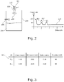
- Fig. 2 shows a typical application of such a device.
- the level gauge 201 emits a signal 203 via the antenna 202 in the direction of the medium 204 to be measured.
- the level gauge itself can determine the distance to the medium with the help of ultrasound, radar, laser or the principle of the guided microwave. Accordingly, both ultrasonic waves and electromagnetic waves come into consideration as signals.
- the medium 204 reflects the impinging wave back to the meter where it is received and processed.
- the radiated signal is also reflected by vessel installations, for example a built-in tube 205.
- the echo curve 206 received in the fill level measuring device 206 can thus contain, in addition to the fill level echo 207 caused by the fill level 204, also echoes 208 of permanently installed defects 205, which are referred to below as false echoes.
- the product container 209 has a cylindrical shape in the present example.
- the echo curve 206 is examined by the arithmetic unit 210 for echoes.
- an echo list 301 according to the scheme of FIG Fig. 3 generated.
- the echo list also contains another echo E1 or 207 generated by the medium 204.
- echo lists represent only a specific implementation of an echo list.
- echo lists are also common with other or changed features of an echo.
- the local progressions of the individual echoes of the echo list determined in the form of a track list are further processed in the block "motion detection" 104.
- the aim of this processing step is to make a statement about which echoes move over several measurements relative to their echo location, and which behave stationary with respect to the determined echo location.
- the methods used at this point can also be made according to the current state of the art and are, for example, in EP 10 156 793.1 described in detail.
- the amplitude adjuster 105 assumes a central role within the signal processing chain of the level gauge. It should be noted at this point that the logical division of the algorithmic steps to be performed according to Fig. 1 represents only one possible variant. In many cases, the same process steps are divided into differently defined blocks. For example, the functionality of the "amplitude adjuster" 105 may also be implemented within the "decision on level” 106.
- the task of the amplitude evaluator 105 is to evaluate the echoes of the currently present echo list 301 with regard to its current amplitude.
- the idea underlying this method step is derived from the general radar equation for the case of a radar level measuring device, which is described in detail, for example, in "Meinke / Gundlach: Taschenbuch der Hochfrequenztechnik". In the case of a level measurement with ultrasound or laser corresponding physical laws can be found in the relevant literature.
- the amplitude evaluator determines the theoretically expected echo amplitude for the various echoes of the echo list using mathematical equations, and compares these with the actually received amplitude of the respectively considered echo. If the actually received echo amplitude corresponds to the theoretically expected amplitude of a product reflection at the corresponding location, this relationship is transmitted in the form of a high amplitude evaluation of the corresponding echo to the decision to fill level 106. If the received amplitude deviates greatly from the echo amplitude to be expected from a product reflection, this leads to a low amplitude evaluation.
- the validity of the radar equation can be limited to reflectors which are located in the far field of a transmitting antenna. This condition is sufficiently fulfilled if and only if the distance between object and transmitter is significantly greater than the wavelength of the radar signal. In the present case of a level radar device with a wavelength of typically 5 cm, this condition is sufficiently fulfilled. In addition, it is required as a further prerequisite that the reflector to be measured is radiated over a large area by the transmitting lobe of the radar antenna used.
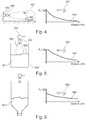
- Fig. 4 shows an untypical but basically possible application of a level measuring device in the context of object monitoring.
- the object 401 to be monitored is located at a sufficiently great distance from the measuring device 402, and is radiated over a large area by the transmitting lobe 403 of the radar antenna 404.
- the transmitting lobe of the radar antenna depends directly on the structure of the antenna, and can be determined with standard simulation programs for the particular type of antenna used with sufficient accuracy in advance.
- the boundary conditions for the application of the radar equation for determining the theoretically expected reception level are for the application of the Fig.
- Fig. 5 a further arrangement for measuring the level of a medium 501 within a container 502 is shown. It can be seen directly from the illustration that the antenna lobe 505 belonging to the antenna 503 of the level measuring device 504 is not able to over-radiate the complete surface 506 of the reflecting medium 501 due to the small distance to the filling material. In addition, a transition into the near zone of the antenna can occur, in particular in the case of small containers, due to the resulting short distances to the filling material. Both effects lead to the fact that the amplitude reflected by the product can no longer be predicted with sufficient accuracy by the radar equation.
- the expected amplitude A L can be determined approximately in advance according to a function 507 which depends on the inverse distance d to the object, multiplied by the exponent three 508 (A L ⁇ f (d -3 )).
- the function for calculating the expected reception amplitude depends in many respects on the geometry of the container 502, the dielectric constant of the medium 501 and also of the antenna 503 used, which results in relatively extensive input of parameters necessary.
- Fig. 6 shows a corresponding arrangement.
- Empirical observations suggest a course 602 of the expected amplitude values, which is a function 603 as a function of the inverse square distance of the reflector (A L ⁇ f (d -2 )).
- a L ⁇ f (d -2 ) the inverse square distance of the reflector
- the present invention provides a suitable method for determining an expected value for the amplitude of the level echo generated by the product surface.
- Fig. 7 shown construction of a signal processing unit largely corresponds to the structure Fig. 1 , but differs by the newly added processing unit "Amplitude Profiler" 701 and the modified processing unit "Amplitude Evaluator” 702.
- the block "amplitude profiler” 701 is advantageously used.
- the task of this unit is to continuously monitor the level determined by the "decision on level” block in order to create a profile of the amplitude values of the level echo so far observed.
- This amplitude profile is made available to the amplitude evaluator 702, which in turn enables it to calculate the expected amplitude of the fill level echo at a specific amplitude profile on the basis of the transmitted amplitude profile Location to determine.
- Fig. 8 shows a flow chart for amplitude profiling in level gauges.
- the sequence shown is run through in each measuring cycle of the level measuring device.
- the method starts in the start state 801.
- step 802 the current level is determined.
- almost all process steps of a conventional level measuring device are included.
- an echo curve is received in this step, and echoes are extracted.
- the echoes are then examined for movement.
- the amplitudes of the echoes in the amplitude evaluator 702 are evaluated by known methods.
- the amplitude profiler provides a curve with expected amplitude values, which can be firmly defined, for example, by default in the factory.
- a decision is calculated on the current level echo, and provided this level echo to the outside in a structured form.
- Fig. 10 shows an example of such a structure, which in addition to the location of the level echo also includes its amplitude and the reliability of the decision.
- step 803 the provided level echo information is examined by the amplitude profiler 701. If a valid level echo has been found, the program branches to step 804. Otherwise, the method ends directly in the end state 807.
- step 804 the reliability of the level echo information is considered. In other words, it is examined at this point whether the "decision on level" block 106 has made its selection of an echo as level echo with sufficiently high certainty.
- a measure of the security of the decision for example, in the structure in Fig. 10 included reliability of Decision, which can be derived, for example, from the signal-to-noise ratio of the level echo.
- a measure of the security of the decision can be according to another embodiment, the amount of movement of the level echo.
- step 806 the amplitude profile within the amplitude profiler 701 is now updated.
- the amplitude in advance contained in the main memory at the location of the current level echo is replaced within this process step by the amplitude of the current level echo.
- Fig. 9 shows by way of example the sequence steps of the method based on a filling of a container.
- the device will be put into operation at the time to.
- the level measuring device 901 may decide on the basis of the currently present echo curve 902 for the echo E3 or 903 as the current fill level.
- the amplitude profiler 701 adopts the echo amplitude of the fill level echo as a new interpolation point 904 in the amplitude profile 905 it manages.
- the echo E5 or 907 is identified as the fill level on the basis of the echo curve 906.
- the amplitude profiler 701 updates its amplitude profile 905 about the interpolation point 908 on the basis of this decision.
- the amplitude profile 905 is updated continuously at the times t 2 , t 3 , t 4 by supplementing by the interpolation points 909, 910, 911.
- the amplitude profiler has a completely learned amplitude profile 905 of the current application which can subsequently be used for the evaluation of echo lists.
- the learned amplitude profile is advantageously copied into a non-volatile memory area of the sensor in order to be immediately available again after a power failure when the device is restarted.
- the storage in the non-volatile memory area can be done in each measurement cycle, or even in a predefined time grid or event-controlled, for example, when changing the level.
- the proposed embodiment offers the advantage over the current state of the art of producing an exact, application-specific image of the amplitude of the fill level echo without requiring an external, user-initiated action.
- the once determined amplitude is reproduced with high accuracy again when reaching a certain filling level of the medium, as far as it is the medium in the container to a medium with a quiet surface.
- Fig. 11 clarifies the problem by means of a moving surface of a liquid.
- an amplitude of, for example, 70 dB is determined for the level echo EF0 1105, and stored by the amplitude profiler 701 in the amplitude profile 905 as a reference point.
- a trumpet 1103 will be formed instead of the flat liquid surface 1102, which will also move around the agitator 1101.
- the level measuring device 1104 will now detect an echo EF 1 1106 at an identical location, which due to the restless reflection surface 1103 only has a reduced amplitude of, for example, 55 dB.
- the amplitude profiler 701 may now be modified in such a way that it is enabled to calculate a statistic with regard to the amplitude values of the level echo which have been transmitted to it.
- Fig. 12 shows the amplitude profile as it can be created by an amplitude profiler extended by the statistics calculation.
- the amplitude profile in the present example consists of the mean value curve 1202, which can be continuously calculated by forming the mean values of all fill level amplitudes at one position.
- the curve 1201 describes the maximum amplitude value of an echo detected at one location; the curve 1203 describes the minimum fill level amplitude value detected at one location.
- the amplitude evaluator 702 may now be given all three statistics curves 1201, 1202, 1203.
- An echo of the echo list is therefore given a high amplitude evaluation by the amplitude evaluator 702 if and only if its amplitude is in the range between the minimum curve 1203 and the maximum curve 1201.
- the method it may also be possible to derive the upper statistical curve 1201 and the lower statistical curve 1202 from other statistical relationships, for example the variance.
- the determined statistical values can be stored in the volatile and / or non-volatile memory area of a fill level measuring device. The storage can be done in each measurement cycle, or even in a pre-defined time frame or event-controlled, for example, when changing the level.
- Fig. 13 shows a particularly advantageous application of the method according to the invention with reference to a container 1301, which is to be filled completely by way of example.
- the standard blocking distance B 1302 which is typically 50 cm between filling level meter and the medium to be measured, is undercut in the case of level measuring instruments, this is generally referred to as overfilling of the container.
- This overfill represents an unspecified application of a level gauge, and must be prevented by the user in most cases. Background of this requirement is that in the range to, for example, 50 cm, a relatively strong reflection 1303 of the antenna of the level measuring device is received.
- a level gauge detects an inadmissible overfilling of a container, it can respond to it in a targeted manner. For example, it may be possible to output a level of 110% outwardly to notify the user that the container is overfilled. Furthermore, it may also be possible to output a disturbance current via a 4 to 20 mA interface to the user notify that the system is operated outside the current specification.
- the occurrence of an overfill situation can be stored persistently by the device in an event memory in order to facilitate a targeted problem analysis in the event of a possibly necessary service intervention.
- the level measuring device 1308 emits a signal in the direction of the product surface 1304 to be measured.
- the product is located in an upwardly closed container 1301.
- the echo curve 1309 subsequently received by the device contains, in addition to the reflection EL1 1305 caused by the product, a further reflection EM1 1310, which is caused by a multiple reflection medium - container cover - medium 1315. It is further assumed that in the previous operation of the level measuring device 1308 of the amplitude profiler 701 contained therein could already create an amplitude profile 1311 of the container.
- the amplitude profile 1311 of the container is also shown in the coordinate system of the echo curve representation.
- the received echo curve 1312 in turn includes an echo EL2 1306 caused by the product surface 1304 and an echo EM2 1313 caused by multiple reflection.
- the amplitude evaluator 702 when comparing the amplitude of the echo EM3 1314 with the expected amplitude of the amplitude profile 1311 at the location of the echo EM3 that they deviate very greatly from one another. Consequently, the echo EM3 can not be the echo caused by the product surface 1304. The level gauge can therefore automatically close to an overfilling of the container.
- the amplitude profile generated dynamically by the device opens up new possibilities for algorithmic evaluation.
- Fig. 14 shows an electronics unit 1400 according to an embodiment of the invention.
- the electronic unit has inter alia a computing unit 210, which is provided for determining the functional relationship.
- the arithmetic unit 210 is connected to a memory 1401.
- the memory 1401 has a non-volatile memory area 1403, in which, for example, the functional relationship, statistical characteristics for the level amplitude and / or other important information can be stored, which are then available even after a restart of the level gauge.
- the computing unit 210 is connected to the transmit / receive antenna arrangement 202.
- the antenna arrangement 202 transmits a transmission signal to the product surface 1304, which is reflected there and received as a reception signal 1405 from the antenna arrangement.
- a higher-level controller 1402 is provided, which is part of the electronic unit 1400 or at least connected to the electronic unit 1400. This higher-level control can support or control the arithmetic unit 210.
Claims (15)
- Unité électronique (1400) pour un appareil de mesure de niveau (901) destiné à la détermination d'un niveau, l'unité électronique comprenant :une unité de calcul (210) pour la détermination d'une relation fonctionnelle (905) entre la distance entre une surface de la charge et l'appareil de mesure de niveau (901) et une amplitude d'une part du signal de réception, réfléchie par la surface de la charge et reçue par l'appareil de mesure de niveau (901) ;un profileur d'amplitude (701) pour établir un profil des valeurs d'amplitude, observées jusqu'à présent, de l'écho de niveau pour différents niveaux ; etun évaluateur d'amplitude (702) pour déterminer une amplitude escomptée de l'écho de niveau en une position définie de l'écho à l'aide du profil d'amplitude et pour comparer l'amplitude de l'écho à l'amplitude escomptée.
- Unité électronique (1400) selon la revendication 1, comprenant en outre :une mémoire (1401) ;la relation fonctionnelle (905) étant mémorisée en forme de points d'appui (904, 908, 909, 910, 911) dans la mémoire.
- Unité électronique (1400) selon la revendication 2,la mémoire (1401) présentant une zone de mémoire non volatile (1403) ;la survenance d'une situation de surcharge, la relation fonctionnelle (905) et/ou la au moins une valeur caractéristique statistique (1201, 1202, 1203) pour l'amplitude de niveau étant mémorisées dans la zone de mémoire non volatile.
- Appareil de mesure de niveau (901) avec une unité électronique (1400) selon l'une des revendications 1 à 3.
- Utilisation d'un appareil de mesure de niveau (901) selon la revendication 4 dans une application, dans laquelle peut survenir une surcharge.
- Procédé de détermination d'un niveau par un appareil de mesure de niveau (901), le procédé comprenant les étapes :émission d'un signal (1404) en direction d'une surface d'une charge :détection d'un signal de réception (1405) correspondant au signal d'émission ;détermination d'une relation fonctionnelle (905) entre la distance entre la surface de la charge et l'appareil de mesure de niveau (901) et une amplitude d'une part du signal de réception, réfléchie par la surface de la charge et reçue par l'appareil de mesure de niveau (901) ;établissement d'un profil des valeurs d'amplitude, observées jusqu'à présent, de l'écho de niveau pour différents niveaux ;détermination d'une amplitude escomptée de l'écho de niveau en une position définie de l'écho à l'aide du profil d'amplitude ;comparaison de l'amplitude de l'écho et de l'amplitude escomptée.
- Procédé selon la revendication 6,la relation fonctionnelle (905) étant élaborée par adaptation des coefficients d'une équation mathématique (508, 603).
- Procédé selon l'une des revendications 6 et 7,la relation fonctionnelle (905) étant utilisée pour l'évaluation des échos d'une liste échos (301).
- Procédé selon l'une des revendications 6 à 8,la détermination de la relation fonctionnelle (905) n'étant réalisée que lorsque l'appareil de mesure de niveau identifie le niveau avec une fiabilité élevée.
- Procédé selon l'une des revendications 6 à 9,la détermination de la relation fonctionnelle (905) n'étant réalisée que lorsque l'écho (903, 907) de la surface de la charge se modifie quant à sa position pendant plusieurs cycles de mesure.
- Procédé selon l'une des revendications 6 à 10,au moins une valeur caractéristique statistique (1201, 1202, 1203) pour l'amplitude de niveau étant déterminée lors de la détermination de la relation fonctionnelle (905).
- Procédé selon la revendication 11,la au moins une valeur caractéristique statistique (1201, 1202, 1203) pour l'amplitude de niveau étant utilisée pour l'évaluation des échos d'une liste échos (301).
- Procédé selon l'une des revendications 6 à 12,la relation fonctionnelle (905) étant utilisée pour détecter la survenance d'une situation de surcharge.
- Procédé selon la revendication 13,la survenance de la situation de surcharge étant signalée à l'utilisateur et/ou à une commande de niveau supérieur (1402).
- Procédé selon la revendication 14,les informations mémorisées dans une zone de mémoire non volatile (1403) étant lues lors de la remise en service de l'appareil de mesure et utilisées pour l'évaluation d'échos.
Priority Applications (4)
| Application Number | Priority Date | Filing Date | Title |
|---|---|---|---|
| EP10170031.8A EP2418465B1 (fr) | 2010-07-19 | 2010-07-19 | Profilage d'amplitude dans des appareils de mesure du niveau de remplissage |
| US13/182,636 US8776594B2 (en) | 2010-07-19 | 2011-07-14 | Amplitude profiling in filling-level measuring devices |
| CN201110204466.XA CN102338654B (zh) | 2010-07-19 | 2011-07-15 | 物位测量装置及其电子单元和用于确定物位的方法 |
| BRPI1103618-4A BRPI1103618B1 (pt) | 2010-07-19 | 2011-07-18 | unidade eletrônica, dispositivo de medição de nível de preenchimento e método para a determinação de um nível de preenchimento |
Applications Claiming Priority (1)
| Application Number | Priority Date | Filing Date | Title |
|---|---|---|---|
| EP10170031.8A EP2418465B1 (fr) | 2010-07-19 | 2010-07-19 | Profilage d'amplitude dans des appareils de mesure du niveau de remplissage |
Publications (2)
| Publication Number | Publication Date |
|---|---|
| EP2418465A1 EP2418465A1 (fr) | 2012-02-15 |
| EP2418465B1 true EP2418465B1 (fr) | 2017-02-22 |
Family
ID=43126908
Family Applications (1)
| Application Number | Title | Priority Date | Filing Date |
|---|---|---|---|
| EP10170031.8A Active EP2418465B1 (fr) | 2010-07-19 | 2010-07-19 | Profilage d'amplitude dans des appareils de mesure du niveau de remplissage |
Country Status (4)
| Country | Link |
|---|---|
| US (1) | US8776594B2 (fr) |
| EP (1) | EP2418465B1 (fr) |
| CN (1) | CN102338654B (fr) |
| BR (1) | BRPI1103618B1 (fr) |
Families Citing this family (21)
| Publication number | Priority date | Publication date | Assignee | Title |
|---|---|---|---|---|
| EP2442129B1 (fr) * | 2010-10-18 | 2016-03-23 | Siemens Aktiengesellschaft | Procédé de traitement d'un profil d'amplitude d'écho généré par un système de télémétrie par impulsion-écho |
| EP2584324B1 (fr) * | 2011-10-17 | 2018-09-19 | VEGA Grieshaber KG | Appareil de mesure du niveau de remplissage et procédé de détermination d'un rapport fonctionnel entre différentes pistes |
| DE102012101725A1 (de) * | 2012-03-01 | 2013-09-05 | Sick Ag | Verfahren zur Füllstandsmessung |
| DE102012007979A1 (de) | 2012-04-24 | 2013-10-24 | Krohne Messtechnik Gmbh | Verfahren zur Bestimmung des Füllstandes eines Mediums und entsprechende Vorrichtung |
| DE102012104858A1 (de) * | 2012-06-05 | 2013-12-05 | Endress + Hauser Gmbh + Co. Kg | Verfahren zur Füllstandsmessung nach dem Laufzeitprinzip |
| DE102012107146A1 (de) | 2012-08-03 | 2014-02-20 | Endress + Hauser Gmbh + Co. Kg | Verfahren zur Bestimmung und/oder Überwachung des Füllstands eines Mediums in einem Behälter |
| DE102012112749A1 (de) | 2012-12-20 | 2014-07-10 | Endress + Hauser Gmbh + Co. Kg | Verfahren zur Auswertung von Messsignalen eines Füllstandsmessgeräts |
| DE102013103532A1 (de) * | 2013-04-09 | 2014-10-09 | Endress + Hauser Gmbh + Co. Kg | Verfahren zur Füllstandsmessung nach dem Laufzeitprinzip |
| CN105277941B (zh) * | 2014-07-22 | 2018-01-23 | A.P.M.自动化解决方案公司 | 用于基于内容物估计来检测仓内的障碍物的系统和方法 |
| HUE037717T2 (hu) * | 2015-07-02 | 2018-09-28 | Grieshaber Vega Kg | Eljárás töltésszintmérésre és töltésszintmérõ készülék |
| DE102015111595B4 (de) * | 2015-07-16 | 2023-03-30 | Endress+Hauser SE+Co. KG | Füllstandmessgerät zur Ermittlung und Überwachung eines Füllstands |
| US9912420B1 (en) * | 2016-04-05 | 2018-03-06 | National Technology & Engineering Solutions Of Sandia, Llc | Robust power detector for wideband signals among many single tone signals |
| EP3435043B1 (fr) | 2017-07-25 | 2020-04-29 | VEGA Grieshaber KG | Jauge radar, procédé et éléments de programme pour faire fonctionner un jauge radar |
| DE102018123432A1 (de) * | 2018-09-24 | 2020-03-26 | Endress+Hauser SE+Co. KG | Detektion von Ereignis-abhängigen Zuständen bei Füllstandsmessung |
| DE102018124606A1 (de) * | 2018-10-05 | 2020-04-09 | Endress+Hauser SE+Co. KG | Verfahren zu Füllstandsmessung |
| CN111006743B (zh) * | 2019-12-05 | 2021-07-02 | 水利部南京水利水文自动化研究所 | 一种基于平面雷达水位计的水位测量排除干扰的方法 |
| DE102020210517A1 (de) | 2020-08-19 | 2022-02-24 | Vega Grieshaber Kg | Sensor zur Bestimmung eines Füllstands, Sensorsystem, Verwendung und Verfahren |
| EP4012356B1 (fr) * | 2020-12-11 | 2023-08-30 | Pepperl+Fuchs SE | Procédé de détermination d'un niveau de remplissage, capteur à ultrasons et dispositif de mesure permettant de déterminer un volume d'un produit de remplissage |
| HRP20231054T1 (hr) * | 2021-06-07 | 2023-12-22 | Vega Grieshaber Kg | Radar razine punjenja s promjenjivom točnošću kvantizacije |
| US20230243688A1 (en) * | 2022-01-31 | 2023-08-03 | Abb Schweiz Ag | Systems and methods for determining a fill level |
| EP4266012A1 (fr) * | 2022-04-19 | 2023-10-25 | VEGA Grieshaber KG | Appareil de mesure de niveau de remplissage à degré de qualité d'une fonction de surveillance pouvant être sélectionné |
Family Cites Families (16)
| Publication number | Priority date | Publication date | Assignee | Title |
|---|---|---|---|---|
| DE4218303C1 (de) | 1992-06-03 | 1994-03-03 | Endress Hauser Gmbh Co | Verfahren und Anordnung zur Abstandsmessung nach dem Impulslaufzeitprinzip |
| DE4308373C2 (de) * | 1993-03-16 | 1995-04-13 | Siemens Ag | Verfahren zur Erkennung und Separation von Nutz- und Störechos im Empfangssignal von Abstandssensoren, welche nach dem Impuls-Echo-Prinzip arbeiten |
| DE4332071C2 (de) | 1993-09-21 | 1995-09-07 | Endress Hauser Gmbh Co | Verfahren zur Füllstandsmessung nach dem Radarprinzip |
| GB2338132B (en) * | 1998-06-02 | 2003-05-28 | Federal Ind Ind Group Inc | Echo detection in echo ranging systems |
| DE10105652A1 (de) * | 2001-02-08 | 2002-08-14 | Grieshaber Vega Kg | Verfahren und Vorrichtung zur Grobunterscheidung eines Füllgutes in einem Behälter in Flüssigkeit oder Schüttgut |
| CN1270167C (zh) * | 2001-07-27 | 2006-08-16 | 恩德莱斯和豪瑟尔两合公司 | 用于估计基于传播时间的测量设备的测量信号的方法 |
| DE10260962A1 (de) | 2002-12-20 | 2004-07-01 | Endress + Hauser Gmbh + Co. Kg | Füllstandsmeßgerät und Verfahren zur Füllstandsmessung nach dem Laufzeitprinzip |
| US6816436B1 (en) * | 2003-05-21 | 2004-11-09 | Siemens Milltronics Process Instruments Inc. | Method for echo processing in time-of-flight or level measurement systems |
| US7098843B2 (en) | 2004-05-27 | 2006-08-29 | Saab Rosemount Tank Radar Ab | Automatic sensitivity control for radar level gauges |
| DE102004055551A1 (de) * | 2004-11-17 | 2006-05-18 | Endress + Hauser Gmbh + Co. Kg | Verfahren zur Auswertung und Korrektur von Gesamtmesssignalen |
| DE102005003152A1 (de) * | 2005-01-21 | 2006-07-27 | Endress + Hauser Gmbh + Co. Kg | Verfahren zur Überprüfung der ordnungsgemäßen Funktion eines Füllstandmessgeräts |
| DE602006018265D1 (de) * | 2005-02-28 | 2010-12-30 | A P M Automation Solutions Ltd | System und verfahren zur messung des inhalts eines bin |
| GB0705187D0 (en) * | 2007-03-17 | 2007-04-25 | Mobrey Ltd | Improvements in or relating to level measurement |
| DE102007042042B4 (de) * | 2007-09-05 | 2020-03-26 | Endress+Hauser SE+Co. KG | Verfahren zur Ermittlung und Überwachung des Füllstands eines Mediums in einem Behälter nach einem Laufzeitmessverfahren |
| AU2008300826B2 (en) | 2007-09-20 | 2012-08-16 | Vega Grieshaber Kg | Detailfunction based measurement |
| HUE031382T2 (en) * | 2008-05-27 | 2017-07-28 | Grieshaber Vega Kg | Echoel shape evaluation for charge level sensors |
-
2010
- 2010-07-19 EP EP10170031.8A patent/EP2418465B1/fr active Active
-
2011
- 2011-07-14 US US13/182,636 patent/US8776594B2/en active Active
- 2011-07-15 CN CN201110204466.XA patent/CN102338654B/zh active Active
- 2011-07-18 BR BRPI1103618-4A patent/BRPI1103618B1/pt active IP Right Grant
Non-Patent Citations (1)
| Title |
|---|
| None * |
Also Published As
| Publication number | Publication date |
|---|---|
| CN102338654B (zh) | 2015-08-26 |
| CN102338654A (zh) | 2012-02-01 |
| US8776594B2 (en) | 2014-07-15 |
| US20120174664A1 (en) | 2012-07-12 |
| EP2418465A1 (fr) | 2012-02-15 |
| BRPI1103618B1 (pt) | 2020-08-18 |
| BRPI1103618A2 (pt) | 2013-01-22 |
Similar Documents
| Publication | Publication Date | Title |
|---|---|---|
| EP2418465B1 (fr) | Profilage d'amplitude dans des appareils de mesure du niveau de remplissage | |
| EP2372319B1 (fr) | Accumulation d'écho parasite dans des bruits de récipients | |
| EP0689679B1 (fr) | Procede de reconnaissance et de discrimination entre des echos utiles et des echos parasites dans le signal de reception de capteurs de la distance fonctionnant selon le principe d'impulsions-echos | |
| DE102009001010B4 (de) | Verfahren zur Ermittlung und Überwachung des Füllstands eines Mediums in einem Behälter nach einem Laufzeitmessverfahren | |
| EP1523661B1 (fr) | Procede et dispositif permettant de determiner une plage de valeurs escomptees pour un echo de niveau et un echo parasite | |
| EP2104839A1 (fr) | Procédé pour déterminer et surveiller le niveau d'un fluide dans un récipient selon un procédé de mesure du temps de propagation | |
| EP1839017B1 (fr) | Procede pour verifier le bon fonctionnement d'un dispositif de mesure de niveau de remplissage | |
| EP2366983B1 (fr) | Reconnaissance de mobilité dans un appareil de mesure de niveau | |
| EP2626676B1 (fr) | Dispositif et procédé de correction d'un décalage | |
| DE102007042042A1 (de) | Verfahren zur Ermittlung und Überwachung des Füllstands eines Mediums in einem Behälter nach einem Laufzeitmessverfahren | |
| DE102012107146A1 (de) | Verfahren zur Bestimmung und/oder Überwachung des Füllstands eines Mediums in einem Behälter | |
| EP2657664B1 (fr) | Procédé de détermination du niveau de remplissage d'un fluide et dispositif correspondant | |
| EP3025128B1 (fr) | Procédé pour déterminer et surveiller le niveau d'un fluide dans un récipient selon un procédé de mesure du temps de propagation | |
| DE102010044182A1 (de) | Verfahren zum Einstellen eines Messgeräts | |
| EP3435043B1 (fr) | Jauge radar, procédé et éléments de programme pour faire fonctionner un jauge radar | |
| WO2007077079A1 (fr) | Procedes de determination et de controle du niveau de remplissage d'un fluide dans un contenant selon le principe de la duree de parcours | |
| EP2554956A1 (fr) | Suivi en fonction de la mobilité | |
| EP2527805A1 (fr) | Dispositif d'évaluation et procédé de détermination d'une grandeur caractéristique pour la position d'une surface limite dans un récipient | |
| DE102004055551A1 (de) | Verfahren zur Auswertung und Korrektur von Gesamtmesssignalen | |
| EP2309235A1 (fr) | Traitement de signal à base de segments | |
| EP3152529B1 (fr) | Détermination de profil de défauts et de récipient | |
| EP3857184B1 (fr) | Détection de formation de mousse d'un produit de remplissage dans un récipient lors d'une mesure de niveau de remplissage | |
| EP2739946B1 (fr) | Relation lineaire entre pistes | |
| EP3746753B1 (fr) | Procédé de détection d'états d'erreur potentiels sur un dispositif de mesure de remplissage à base de fmcw | |
| EP1283412A2 (fr) | Procédé et dispositif de détection d'une opération de remplissage |
Legal Events
| Date | Code | Title | Description |
|---|---|---|---|
| AK | Designated contracting states |
Kind code of ref document: A1 Designated state(s): AL AT BE BG CH CY CZ DE DK EE ES FI FR GB GR HR HU IE IS IT LI LT LU LV MC MK MT NL NO PL PT RO SE SI SK SM TR |
|
| AX | Request for extension of the european patent |
Extension state: BA ME RS |
|
| PUAI | Public reference made under article 153(3) epc to a published international application that has entered the european phase |
Free format text: ORIGINAL CODE: 0009012 |
|
| 17P | Request for examination filed |
Effective date: 20120604 |
|
| 17Q | First examination report despatched |
Effective date: 20150902 |
|
| REG | Reference to a national code |
Ref country code: DE Ref legal event code: R079 Ref document number: 502010013194 Country of ref document: DE Free format text: PREVIOUS MAIN CLASS: G01F0023000000 Ipc: G01F0025000000 |
|
| GRAP | Despatch of communication of intention to grant a patent |
Free format text: ORIGINAL CODE: EPIDOSNIGR1 |
|
| STAA | Information on the status of an ep patent application or granted ep patent |
Free format text: STATUS: GRANT OF PATENT IS INTENDED |
|
| RIC1 | Information provided on ipc code assigned before grant |
Ipc: G01F 23/296 20060101ALI20161018BHEP Ipc: G01S 13/88 20060101ALI20161018BHEP Ipc: G01S 7/35 20060101ALI20161018BHEP Ipc: G01F 23/284 20060101ALI20161018BHEP Ipc: G01F 25/00 20060101AFI20161018BHEP Ipc: G01S 13/08 20060101ALI20161018BHEP Ipc: G01S 7/285 20060101ALI20161018BHEP |
|
| INTG | Intention to grant announced |
Effective date: 20161107 |
|
| GRAS | Grant fee paid |
Free format text: ORIGINAL CODE: EPIDOSNIGR3 |
|
| GRAA | (expected) grant |
Free format text: ORIGINAL CODE: 0009210 |
|
| STAA | Information on the status of an ep patent application or granted ep patent |
Free format text: STATUS: THE PATENT HAS BEEN GRANTED |
|
| AK | Designated contracting states |
Kind code of ref document: B1 Designated state(s): AL AT BE BG CH CY CZ DE DK EE ES FI FR GB GR HR HU IE IS IT LI LT LU LV MC MK MT NL NO PL PT RO SE SI SK SM TR |
|
| REG | Reference to a national code |
Ref country code: GB Ref legal event code: FG4D Free format text: NOT ENGLISH |
|
| REG | Reference to a national code |
Ref country code: CH Ref legal event code: EP |
|
| REG | Reference to a national code |
Ref country code: AT Ref legal event code: REF Ref document number: 869611 Country of ref document: AT Kind code of ref document: T Effective date: 20170315 |
|
| REG | Reference to a national code |
Ref country code: IE Ref legal event code: FG4D Free format text: LANGUAGE OF EP DOCUMENT: GERMAN |
|
| REG | Reference to a national code |
Ref country code: DE Ref legal event code: R096 Ref document number: 502010013194 Country of ref document: DE |
|
| REG | Reference to a national code |
Ref country code: NL Ref legal event code: FP |
|
| REG | Reference to a national code |
Ref country code: SE Ref legal event code: TRGR |
|
| REG | Reference to a national code |
Ref country code: LT Ref legal event code: MG4D |
|
| PG25 | Lapsed in a contracting state [announced via postgrant information from national office to epo] |
Ref country code: LT Free format text: LAPSE BECAUSE OF FAILURE TO SUBMIT A TRANSLATION OF THE DESCRIPTION OR TO PAY THE FEE WITHIN THE PRESCRIBED TIME-LIMIT Effective date: 20170222 Ref country code: NO Free format text: LAPSE BECAUSE OF FAILURE TO SUBMIT A TRANSLATION OF THE DESCRIPTION OR TO PAY THE FEE WITHIN THE PRESCRIBED TIME-LIMIT Effective date: 20170522 Ref country code: FI Free format text: LAPSE BECAUSE OF FAILURE TO SUBMIT A TRANSLATION OF THE DESCRIPTION OR TO PAY THE FEE WITHIN THE PRESCRIBED TIME-LIMIT Effective date: 20170222 Ref country code: HR Free format text: LAPSE BECAUSE OF FAILURE TO SUBMIT A TRANSLATION OF THE DESCRIPTION OR TO PAY THE FEE WITHIN THE PRESCRIBED TIME-LIMIT Effective date: 20170222 Ref country code: GR Free format text: LAPSE BECAUSE OF FAILURE TO SUBMIT A TRANSLATION OF THE DESCRIPTION OR TO PAY THE FEE WITHIN THE PRESCRIBED TIME-LIMIT Effective date: 20170523 |
|
| PG25 | Lapsed in a contracting state [announced via postgrant information from national office to epo] |
Ref country code: PT Free format text: LAPSE BECAUSE OF FAILURE TO SUBMIT A TRANSLATION OF THE DESCRIPTION OR TO PAY THE FEE WITHIN THE PRESCRIBED TIME-LIMIT Effective date: 20170622 Ref country code: LV Free format text: LAPSE BECAUSE OF FAILURE TO SUBMIT A TRANSLATION OF THE DESCRIPTION OR TO PAY THE FEE WITHIN THE PRESCRIBED TIME-LIMIT Effective date: 20170222 Ref country code: ES Free format text: LAPSE BECAUSE OF FAILURE TO SUBMIT A TRANSLATION OF THE DESCRIPTION OR TO PAY THE FEE WITHIN THE PRESCRIBED TIME-LIMIT Effective date: 20170222 Ref country code: BG Free format text: LAPSE BECAUSE OF FAILURE TO SUBMIT A TRANSLATION OF THE DESCRIPTION OR TO PAY THE FEE WITHIN THE PRESCRIBED TIME-LIMIT Effective date: 20170522 |
|
| PG25 | Lapsed in a contracting state [announced via postgrant information from national office to epo] |
Ref country code: SK Free format text: LAPSE BECAUSE OF FAILURE TO SUBMIT A TRANSLATION OF THE DESCRIPTION OR TO PAY THE FEE WITHIN THE PRESCRIBED TIME-LIMIT Effective date: 20170222 Ref country code: EE Free format text: LAPSE BECAUSE OF FAILURE TO SUBMIT A TRANSLATION OF THE DESCRIPTION OR TO PAY THE FEE WITHIN THE PRESCRIBED TIME-LIMIT Effective date: 20170222 Ref country code: RO Free format text: LAPSE BECAUSE OF FAILURE TO SUBMIT A TRANSLATION OF THE DESCRIPTION OR TO PAY THE FEE WITHIN THE PRESCRIBED TIME-LIMIT Effective date: 20170222 Ref country code: CZ Free format text: LAPSE BECAUSE OF FAILURE TO SUBMIT A TRANSLATION OF THE DESCRIPTION OR TO PAY THE FEE WITHIN THE PRESCRIBED TIME-LIMIT Effective date: 20170222 Ref country code: IT Free format text: LAPSE BECAUSE OF FAILURE TO SUBMIT A TRANSLATION OF THE DESCRIPTION OR TO PAY THE FEE WITHIN THE PRESCRIBED TIME-LIMIT Effective date: 20170222 |
|
| REG | Reference to a national code |
Ref country code: DE Ref legal event code: R097 Ref document number: 502010013194 Country of ref document: DE |
|
| PG25 | Lapsed in a contracting state [announced via postgrant information from national office to epo] |
Ref country code: SM Free format text: LAPSE BECAUSE OF FAILURE TO SUBMIT A TRANSLATION OF THE DESCRIPTION OR TO PAY THE FEE WITHIN THE PRESCRIBED TIME-LIMIT Effective date: 20170222 Ref country code: DK Free format text: LAPSE BECAUSE OF FAILURE TO SUBMIT A TRANSLATION OF THE DESCRIPTION OR TO PAY THE FEE WITHIN THE PRESCRIBED TIME-LIMIT Effective date: 20170222 Ref country code: PL Free format text: LAPSE BECAUSE OF FAILURE TO SUBMIT A TRANSLATION OF THE DESCRIPTION OR TO PAY THE FEE WITHIN THE PRESCRIBED TIME-LIMIT Effective date: 20170222 |
|
| PLBE | No opposition filed within time limit |
Free format text: ORIGINAL CODE: 0009261 |
|
| STAA | Information on the status of an ep patent application or granted ep patent |
Free format text: STATUS: NO OPPOSITION FILED WITHIN TIME LIMIT |
|
| REG | Reference to a national code |
Ref country code: HU Ref legal event code: AG4A Ref document number: E033944 Country of ref document: HU |
|
| 26N | No opposition filed |
Effective date: 20171123 |
|
| PG25 | Lapsed in a contracting state [announced via postgrant information from national office to epo] |
Ref country code: SI Free format text: LAPSE BECAUSE OF FAILURE TO SUBMIT A TRANSLATION OF THE DESCRIPTION OR TO PAY THE FEE WITHIN THE PRESCRIBED TIME-LIMIT Effective date: 20170222 |
|
| REG | Reference to a national code |
Ref country code: CH Ref legal event code: PL |
|
| REG | Reference to a national code |
Ref country code: IE Ref legal event code: MM4A |
|
| REG | Reference to a national code |
Ref country code: FR Ref legal event code: ST Effective date: 20180330 |
|
| PG25 | Lapsed in a contracting state [announced via postgrant information from national office to epo] |
Ref country code: IE Free format text: LAPSE BECAUSE OF NON-PAYMENT OF DUE FEES Effective date: 20170719 Ref country code: LI Free format text: LAPSE BECAUSE OF NON-PAYMENT OF DUE FEES Effective date: 20170731 Ref country code: CH Free format text: LAPSE BECAUSE OF NON-PAYMENT OF DUE FEES Effective date: 20170731 |
|
| PG25 | Lapsed in a contracting state [announced via postgrant information from national office to epo] |
Ref country code: FR Free format text: LAPSE BECAUSE OF NON-PAYMENT OF DUE FEES Effective date: 20170731 |
|
| REG | Reference to a national code |
Ref country code: BE Ref legal event code: MM Effective date: 20170731 |
|
| PG25 | Lapsed in a contracting state [announced via postgrant information from national office to epo] |
Ref country code: LU Free format text: LAPSE BECAUSE OF NON-PAYMENT OF DUE FEES Effective date: 20170719 |
|
| PG25 | Lapsed in a contracting state [announced via postgrant information from national office to epo] |
Ref country code: BE Free format text: LAPSE BECAUSE OF NON-PAYMENT OF DUE FEES Effective date: 20170731 |
|
| REG | Reference to a national code |
Ref country code: AT Ref legal event code: MM01 Ref document number: 869611 Country of ref document: AT Kind code of ref document: T Effective date: 20170719 |
|
| PG25 | Lapsed in a contracting state [announced via postgrant information from national office to epo] |
Ref country code: MT Free format text: LAPSE BECAUSE OF FAILURE TO SUBMIT A TRANSLATION OF THE DESCRIPTION OR TO PAY THE FEE WITHIN THE PRESCRIBED TIME-LIMIT Effective date: 20170222 |
|
| PG25 | Lapsed in a contracting state [announced via postgrant information from national office to epo] |
Ref country code: AT Free format text: LAPSE BECAUSE OF NON-PAYMENT OF DUE FEES Effective date: 20170719 |
|
| PG25 | Lapsed in a contracting state [announced via postgrant information from national office to epo] |
Ref country code: MC Free format text: LAPSE BECAUSE OF FAILURE TO SUBMIT A TRANSLATION OF THE DESCRIPTION OR TO PAY THE FEE WITHIN THE PRESCRIBED TIME-LIMIT Effective date: 20170222 |
|
| PG25 | Lapsed in a contracting state [announced via postgrant information from national office to epo] |
Ref country code: CY Free format text: LAPSE BECAUSE OF NON-PAYMENT OF DUE FEES Effective date: 20170222 |
|
| PG25 | Lapsed in a contracting state [announced via postgrant information from national office to epo] |
Ref country code: MK Free format text: LAPSE BECAUSE OF FAILURE TO SUBMIT A TRANSLATION OF THE DESCRIPTION OR TO PAY THE FEE WITHIN THE PRESCRIBED TIME-LIMIT Effective date: 20170222 |
|
| PG25 | Lapsed in a contracting state [announced via postgrant information from national office to epo] |
Ref country code: TR Free format text: LAPSE BECAUSE OF FAILURE TO SUBMIT A TRANSLATION OF THE DESCRIPTION OR TO PAY THE FEE WITHIN THE PRESCRIBED TIME-LIMIT Effective date: 20170222 |
|
| PG25 | Lapsed in a contracting state [announced via postgrant information from national office to epo] |
Ref country code: IS Free format text: LAPSE BECAUSE OF FAILURE TO SUBMIT A TRANSLATION OF THE DESCRIPTION OR TO PAY THE FEE WITHIN THE PRESCRIBED TIME-LIMIT Effective date: 20170622 Ref country code: AL Free format text: LAPSE BECAUSE OF FAILURE TO SUBMIT A TRANSLATION OF THE DESCRIPTION OR TO PAY THE FEE WITHIN THE PRESCRIBED TIME-LIMIT Effective date: 20170222 |
|
| P01 | Opt-out of the competence of the unified patent court (upc) registered |
Effective date: 20230525 |
|
| PGFP | Annual fee paid to national office [announced via postgrant information from national office to epo] |
Ref country code: NL Payment date: 20230720 Year of fee payment: 14 |
|
| PGFP | Annual fee paid to national office [announced via postgrant information from national office to epo] |
Ref country code: GB Payment date: 20230724 Year of fee payment: 14 |
|
| PGFP | Annual fee paid to national office [announced via postgrant information from national office to epo] |
Ref country code: SE Payment date: 20230724 Year of fee payment: 14 Ref country code: HU Payment date: 20230717 Year of fee payment: 14 Ref country code: DE Payment date: 20230720 Year of fee payment: 14 |