EP2657664B1 - Procédé de détermination du niveau de remplissage d'un fluide et dispositif correspondant - Google Patents
Procédé de détermination du niveau de remplissage d'un fluide et dispositif correspondant Download PDFInfo
- Publication number
- EP2657664B1 EP2657664B1 EP13001447.5A EP13001447A EP2657664B1 EP 2657664 B1 EP2657664 B1 EP 2657664B1 EP 13001447 A EP13001447 A EP 13001447A EP 2657664 B1 EP2657664 B1 EP 2657664B1
- Authority
- EP
- European Patent Office
- Prior art keywords
- signal
- signals
- received signal
- sub
- evaluation
- Prior art date
- Legal status (The legal status is an assumption and is not a legal conclusion. Google has not performed a legal analysis and makes no representation as to the accuracy of the status listed.)
- Active
Links
Images

Classifications
-
- G—PHYSICS
- G01—MEASURING; TESTING
- G01F—MEASURING VOLUME, VOLUME FLOW, MASS FLOW OR LIQUID LEVEL; METERING BY VOLUME
- G01F23/00—Indicating or measuring liquid level or level of fluent solid material, e.g. indicating in terms of volume or indicating by means of an alarm
- G01F23/22—Indicating or measuring liquid level or level of fluent solid material, e.g. indicating in terms of volume or indicating by means of an alarm by measuring physical variables, other than linear dimensions, pressure or weight, dependent on the level to be measured, e.g. by difference of heat transfer of steam or water
- G01F23/28—Indicating or measuring liquid level or level of fluent solid material, e.g. indicating in terms of volume or indicating by means of an alarm by measuring physical variables, other than linear dimensions, pressure or weight, dependent on the level to be measured, e.g. by difference of heat transfer of steam or water by measuring the variations of parameters of electromagnetic or acoustic waves applied directly to the liquid or fluent solid material
- G01F23/284—Electromagnetic waves
-
- G—PHYSICS
- G01—MEASURING; TESTING
- G01F—MEASURING VOLUME, VOLUME FLOW, MASS FLOW OR LIQUID LEVEL; METERING BY VOLUME
- G01F23/00—Indicating or measuring liquid level or level of fluent solid material, e.g. indicating in terms of volume or indicating by means of an alarm
-
- G—PHYSICS
- G01—MEASURING; TESTING
- G01F—MEASURING VOLUME, VOLUME FLOW, MASS FLOW OR LIQUID LEVEL; METERING BY VOLUME
- G01F23/00—Indicating or measuring liquid level or level of fluent solid material, e.g. indicating in terms of volume or indicating by means of an alarm
- G01F23/22—Indicating or measuring liquid level or level of fluent solid material, e.g. indicating in terms of volume or indicating by means of an alarm by measuring physical variables, other than linear dimensions, pressure or weight, dependent on the level to be measured, e.g. by difference of heat transfer of steam or water
- G01F23/28—Indicating or measuring liquid level or level of fluent solid material, e.g. indicating in terms of volume or indicating by means of an alarm by measuring physical variables, other than linear dimensions, pressure or weight, dependent on the level to be measured, e.g. by difference of heat transfer of steam or water by measuring the variations of parameters of electromagnetic or acoustic waves applied directly to the liquid or fluent solid material
- G01F23/296—Acoustic waves
- G01F23/2961—Acoustic waves for discrete levels
-
- G—PHYSICS
- G01—MEASURING; TESTING
- G01F—MEASURING VOLUME, VOLUME FLOW, MASS FLOW OR LIQUID LEVEL; METERING BY VOLUME
- G01F23/00—Indicating or measuring liquid level or level of fluent solid material, e.g. indicating in terms of volume or indicating by means of an alarm
- G01F23/22—Indicating or measuring liquid level or level of fluent solid material, e.g. indicating in terms of volume or indicating by means of an alarm by measuring physical variables, other than linear dimensions, pressure or weight, dependent on the level to be measured, e.g. by difference of heat transfer of steam or water
- G01F23/28—Indicating or measuring liquid level or level of fluent solid material, e.g. indicating in terms of volume or indicating by means of an alarm by measuring physical variables, other than linear dimensions, pressure or weight, dependent on the level to be measured, e.g. by difference of heat transfer of steam or water by measuring the variations of parameters of electromagnetic or acoustic waves applied directly to the liquid or fluent solid material
- G01F23/296—Acoustic waves
- G01F23/2962—Measuring transit time of reflected waves
-
- G—PHYSICS
- G01—MEASURING; TESTING
- G01F—MEASURING VOLUME, VOLUME FLOW, MASS FLOW OR LIQUID LEVEL; METERING BY VOLUME
- G01F25/00—Testing or calibration of apparatus for measuring volume, volume flow or liquid level or for metering by volume
- G01F25/20—Testing or calibration of apparatus for measuring volume, volume flow or liquid level or for metering by volume of apparatus for measuring liquid level
Definitions
- the invention relates to a method for determining the level of a medium.
- at least one transmission signal is transmitted and received at least one received signal.
- the received signal is evaluated at least with regard to the process variable "level".
- the method for determining the level is intended and that the received signal is evaluated in terms of the level, then it also means such methods in which the level is only monitored, ie where no consistent determinability all levels must be present. Equally, the evaluation of the level not only includes the display of the level, it is also meant that the received signal is processed in terms of level, so for example as current or voltage signal further processing is made available.
- the transmit signal and the receive signal are typically electromagnetic signals in particular, but of course other signals are also suitable, for example sound waves.
- the invention relates to a corresponding device for determining the level of a medium, with at least one transmitting unit for emitting at least one - in particular electromagnetic - transmission signal, with at least one receiving unit for receiving at least one - in particular electromagnetic - received signal, and at least one evaluation unit for evaluating the reception signal.
- radar level gauges are often used to determine the level of media such as liquids, bulk materials or sludges within containers such as tanks, silos or tubes.
- the transit time method implemented by the measuring devices builds on the physical law that the running distance z.
- the travel distance is twice the distance between an antenna emitting and receiving the electromagnetic signal and the surface of the medium.
- the useful echo signal - ie the signal reflected on the surface of the medium - and its transit time are usually determined by means of the so-called echo function or the digitized envelope curve.
- the envelope represents the amplitudes of the echo signals as a function of the distance "antenna - surface of the medium” or the duration of the signal.
- the level can be calculated from the difference between the known distance of the antenna to the bottom of the container and the distance determined by the measurement of the surface of the medium to the antenna.
- the transmitted and received electromagnetic signals are mostly microwave radiation. Measurements by means of ultrasonic waves are also possible.
- the received signal is unfortunately not only from the reflected on the surface of the medium actual echo signal, but also from interfering signals, for example, from multiple reflections, after a partial penetration of the signal in a - especially very dry and a small electrical conductivity exhibiting - medium or by reflections on container walls, welds, heels in the wall, agitators, filling lines or the like.
- interfering signals for example, from multiple reflections, after a partial penetration of the signal in a - especially very dry and a small electrical conductivity exhibiting - medium or by reflections on container walls, welds, heels in the wall, agitators, filling lines or the like.
- In bulk cones generally diffuse and also directed backscatter occur, which originate both from the bulk cone surface and from the bulk cone itself.
- the publication DE 10 2009 055 262 A1 describes a method for level determination from interference signals having received signals.
- comparison signals are determined in a learning phase as a result of application and device-related test signals from expected response signals.
- the received signals are then compared with the comparison signals, and in the event of a deviation beyond a limit, the fill level is determined from the received signals.
- the published patent application also describes further methods for the evaluation of such interference-prone received signals of the prior art discussed.
- the publication EP 2 166 320 A2 describes a method for determining the level of a medium according to the transit time method, wherein the received signal is filtered using a frequency as a filter measure in a sub-signal.
- the disadvantage of the prior art is that mostly only selectively acting and generally expensive methods for signal evaluation are specified.
- the invention is therefore based on the object to propose a method for determining the level of a medium that allows a general and flexible handling of interfering signals in the received signals.
- the indicated object is achieved by the method according to claim 1.
- the received signal is composed essentially and for a simplified consideration of the actual echo signal of the transmission signal on the surface of the medium and of interference signals, which are caused by other reflections, etc.
- the information of the received signal is usually reduced by forming an envelope of the received signal and processing it further. Therefore, the envelope is in particular also a signal derived from the received signal (specifically, for example: envelope of the received signal strength plotted over the Distance / run time).
- the evaluation of the received signal also refers in each case to the evaluation of the envelope or in general to the evaluation of signals derived from the received signal.
- the received signal is processed several times in sub-steps of the evaluation or the processing or several signals derived therefrom are generated.
- the invention is based on the finding that the received signal is composed of a plurality of coherently superimposed backscattered partial signals, each of which can have different signal characteristics. This is accompanied by the fact that the received signal has quasi sections or components with different properties in which possibly overlap different sub-signals, amplify, attenuate or noise each other.
- partial signals originate from different spatial regions when individual signals originate from the reflection on the surface of the medium and other signals originate from reflections on container walls.
- individual signals may differ in their transit time. This can be seen when signals reflected directly on the surface of the medium are compared with multiply reflected signals.
- influencing of the polarization may also occur, so that the partial signals differ in their polarization.
- the sub-signals in the received signal differ from one another and, according to the invention, they also separate from each other again - and if necessary can be selectively evaluated -; This will provide a diversity of information.
- the transmission of the transmission signal, the reception of the reception signal and / or the evaluation of the reception signal is performed in such a way that the reception signal is subdivided into at least one subgroup with respect to the signal properties, ie it is filtered into a plurality of sub-signals. This is done individually when sending, receiving or evaluating or matching combinations are made to achieve the desired effect.
- the diversity of the components contributing to the received signal becomes ordered by their respective properties so as to obtain the filtered subsignals of the subgroups.
- the sub-signals preferably allow an easier (partial) evaluation of the received signal due to their specific dependencies on the type of reflection (s) / scatter (s) they generate.
- the different evaluation criteria in addition to the frequency to a polarization and / or a solid angle and / or a waveform and / or a signal reception time.
- the properties of the received signal are in particular also frequency, polarization, transit time (ie in particular the time between the emission of the transmitted signal and the arrival of the received signal at the receiver) or the solid angle from which the received signal originates.
- the received signal and / or an envelope formed from the received signal and / or the signal derived from the received signal is / are filtered at least with the evaluation criterion frequency or polarization or solid angle or signal reception time as a filter measure in at least one sub-signal.
- the signal dependent on the received signal or derived therefrom for further processing and / or evaluation has been produced in particular from the received signal by the application of a Fourier transformation or an inverse Fourier transformation.
- the Fourier transformation or the inverse Fourier transformation may, in further embodiments, be used multiple times in the filtering or further processing of the respective sub-signals or the respective signals derived therefrom.
- the received signal or a signal dependent thereon (for which the envelope is also to be counted) is subjected to a plurality of filters, between which, if necessary, further different processing steps such as said Fourier transformation are applied.
- the evaluation criteria are, for example, frequency, polarization, solid angle or transit time. For example, if the received signal after the frequency or within Frequency ranges - frequency bands and subfrequency bands - filtered, resulting in subsignals that are within the specified frequencies. The same applies to subsignals related to the polarization or the solid angle.
- z. B. may have bulk material, so that the signals reflected from the surface not only come from a spatial area or from one direction.
- the following embodiments relate to the handling of the filtered signals as sub-signals of the received signal.
- the received signal or a signal dependent thereon and generated therefrom is subdivided into sub-signals according to the filters, and in each case information is extracted from the sub-signals.
- the subsignals are disjoint in one embodiment and partially overlap in another embodiment.
- overlapping frequency bands can be used.
- signal maxima, their position and amplitude or also their shape in the subsignals are determined as information.
- Other parameters that can be obtained from the subsignals and used for the identification or classification are, for example, signal energy, power or amplitude, etc. These parameters can be calculated, for example, from the sampled signals, an envelope detection or a maximum search.
- An evaluation consists, for example, in that a threshold value detection is applied to the sub-signals. Furthermore, these parameters also allow an application as a measure of the probability of reliability of identification. In addition, the parameters obtained from a sub-signal can be used to evaluate another sub-signal, for example better, faster or more easily.
- the sub-signals are compared with known and appropriately stored comparison signals.
- the sub-signals are subject to further filtering with the same evaluation criterion, but with different limits or parameters, or with other evaluation criteria.
- the type of filtering or further processing can generally be fixed or depending on z. B. be adapted to the needs of the signal quality or the type of signals occurring.
- the information of the sub-signals as subsystems of the received signal are suitably combined or compared with one another in order to obtain an overall statement about the process variable. Possibly.
- the extracted information also serve for the optimally adapted further processing of the sub-signals or the received signal.
- the information is used to better adapt the transmission of the transmission signal or the reception of the received signal in the following measurements on the circumstances. Furthermore, plausibility considerations can be realized during the evaluation, or the information from one sub-signal serves to make the evaluation of another sub-signal unambiguous.
- the information comes from subsignals which have the same filtering with respect to the evaluation criterion (eg frequency, polarization, solid angle, time range) but with different parameter sizes (different frequency ranges; horizontal or vertical polarization; Direction of the medium or with lateral inclination, times between zero and a maximum expected time or times that significantly exceed this), or of subsignals as a result of the filtering with different evaluation criteria.
- the advantage consists in the subdivision into sub-signals, which may be easier to evaluate and possibly provide each specific information that are difficult to access or even lost in the received signal due to the overlay. Another advantage results from the fact that even more sophisticated evaluations of more complicated surface structures can be easily realized. Consequently, three-dimensional surface measurements are also undertaken in this way.
- the information from the sub-signal is inventively obtained in that in the sub-signal at least one sub-signal is identified.
- a partial signal is in particular a signal peak of the amplitude, which differs from the surrounding signals. In the simplest case, therefore, a detection of the largest signal is used for this partial signal identification.
- the partial signal may be the actual useful echo from the surface of the medium, but it may also be an interfering signal.
- the determination or monitoring of the filling level as a process variable by means of the transit time method the occurrence of such a partial signal, which is characterized in particular by its shape or its position, is generally associated with a reflection. In other methods (to determine, if necessary, other process variables), these sub-signals thus result due to other peculiarities.
- the invention provides that the identified sub-signal of a class of at least two signal classes - in particular the classes echo signal (ie in the process variable Level a reflection signal from the surface of the medium) or noise signal - is assigned.
- the sub-signal found within the sub-signal resulting from the filtering from the received signal is classified into one of two signal classes or types of sub-signals. It is interesting to distinguish between "echo signal” as the interested signal reflected on the surface of the medium and "noise signal".
- information or parameters extracted from the sub-signals may be used.
- the sub-signals are considered in a consideration as random variables that carry information about the actual useful signals or interference in itself. This results, for example, statistical parameters with respect to the variances of the sub-signals or the correlations with one another. Therefore, statistical methods can also be used to obtain information from the subsignals or to enable identification or classification.
- the sub-signals are subjected to a classification in the previous embodiment after their identification and in particular for the further use of the sub-signals or the information extracted therefrom.
- this is the identification of the partial signal and secondly, its classification into one of the at least two signal classes. In both steps, errors can occur or both statements are associated with a certain degree of certainty or uncertainty. Therefore, in one embodiment, the identification and / or the classification each indicate a probability for the reliability of the identification or the classification. For example, the signal-to-noise ratio or the proximity between adjacent signals, one of which is identified as a partial signal, can be used to assess the identification.
- the merger of the information from the sub-signals into the overall information can be controlled in at least one subsequent step by possibly weighting the information appropriately.
- the measures for the probability of the reliability of the classification for example, methods for multivariant feature analysis in terms of occurrences of the classes "echo signals from the surface of the medium” and "noise” in the feature space can be used, such.
- the distance measures such as Euclidean distance or Mahalanobis distance.
- the received signal is received with adjustable receiving properties and the received signal and / or the derived signal is evaluated in consideration of the reception properties - in particular filtered -.
- a pre-filter is already generated quasi before receiving a filtering in the evaluation by receiving the received signal is received with predetermined or adjustable reception properties. Filtering consists either of attenuating signal areas or completely blanking sections of the signal.
- a certain polarization for the signal reception is set, so that filtering takes place with respect to the polarization already in the acquisition of the received signal.
- the received signal is received only over an adjustable period, so that signals that For example, result from multiple reflections, and therefore have a significantly higher transit time, not received and thereby filtered out.
- the receiving unit is aligned in particular in the form of a receiving antenna such that essentially only signals from the associated spatial area are received.
- the evaluation is coupled with the type of reception in order to make the evaluation suitable and to include the prefiltering.
- the transmission signal is transmitted with adjustable transmission signal properties and the received signal and / or the derived signal is evaluated in consideration of the transmission signal properties - in particular filtered.
- the transmission signal is generated with predefinable properties, which cause the received signal has already been filtered in advance or that some signals have a different weighting, z. As a damping or gain experienced. For the evaluation, this default setting is taken into account or it is included in the filtering and further evaluation.
- the two last embodiments are combined, so that the transmission and the reception are carried out in each case with special properties.
- the evaluation of the resulting received signal reference is then made to both presets, ie the transmission of the transmission signal, the reception of the received signal and the evaluation of the received signal are coordinated with each other.
- a neural network is used for the exact evaluation or setting of the transmission and reception parameters.
- numerical classifiers eg minimum distance classifier, byes classifier, maximum likelihood classifier, nearest neighbor classifier, etc.
- fuzzy classifiers can be used to obtain the information, classification or identification.
- previously known parameters etc. can be used or a learning process is carried out for the evaluation, further processing or filtering, by means of which an independent optimization of the evaluation and / or filtering takes place.
- the previously derived and indicated object is achieved in a further teaching of the invention in an aforementioned device for determining the level of a medium with a device having at least one transmitting unit for emitting at least one - in particular electromagnetic - transmission signal, at least one receiving unit for receiving at least a received signal and at least one evaluation unit for evaluating the received signal.
- the transmitting unit and / or the receiving unit and / or the evaluation unit are configured to implement the above-described method according to at least one of the aforementioned embodiments.
- At least one control unit is provided, which coordinates the transmitting unit and / or the receiving unit and / or the evaluation unit with each other and optionally intervenes in a controlling or regulating manner.
- At least one memory unit is provided, in which the evaluation unit-in particular in the evaluation unit-stores information and / or overall information obtained as history data.
- the evaluation unit uses the history data of the storage unit for obtaining the information and / or the overall information.
- deposited data are used for the evaluation of the current received signal or the envelope or the sub-signals resulting from filtering. If, for example, it is known from a measurement which interference signals are caused by which known and preferably permanently installed interferers, then the evaluation can be correspondingly simplified by, for example, suppressing these interference signals, taking into account the position in the received signal or the amplitude. If, for example, the rate of change of the fill level is also known, it is possible, due to a previous identification of the echo signal from the surface of the medium, to conclude the next value for this echo signal faster and more easily.
- Fig. 1 is a structure for level measurement shown schematically in the with a schematic in the Fig. 2 shown measuring device as in the Fig. 3 obtained received signal is obtained, the measurement of the schematically in Fig. 4 corresponds to the sequence shown.
- Fig. 1 shows a measuring arrangement in which the level of the medium 1 is determined by the measuring device 2.
- the medium 1 is a bulk material, which has no flat surface, but by Schüttkegel a wavy course here.
- the medium 1 is located in a container 3, which here has a shoulder on the left side and a heel on the right side. If the transmission signal of the measuring device 2 occurs on these impurities, this results in signals in the received signal received by the measuring device 2, which in the worst case can lead to confusion with the signal from the surface of the medium 1, so that an incorrect value is calculated for the level.
- the evaluation must also be more elaborate due to the special surface topology of the medium 1 than in the case of a plane surface of a medium.
- the electromagnetic transmission signals first penetrate a little before they are reflected again, so that values for the filling level which are also incorrect here can result.
- a partially closed container 3 as shown here, multiple reflections of the signals may occur, which may possibly be received by the measuring device 2 much later, but which could then lead to the determination of a much too low filling level.
- the transit time of the electromagnetic signals depends on their - generally known - propagation speed and the distance between transmitter and reflective surface of the medium 1 and between the surface and the receiver of the signals.
- transmitter and receiver are realized by the same antenna.
- the solid angle into which the signals are emitted by the measuring device 2 is once dashed and once indicated by a dot-dashed line, this corresponds to the embodiment that a transmitting unit of the measuring device 2 carries out the emission of the transmission signal in different spatial areas.
- Fig. 2 shows a block diagram of an embodiment of a measuring device 2, which has a common transmitting 4 and receiving unit 5 with a horn antenna.
- This transmitting and receiving unit 5 generates the electromagnetic transmission signal and radiates it and also receives the received signal.
- the parameters for the transmission or generation of the transmission signal and the parameters for the reception of the reception signal can be individually and preferably independently changed or set.
- the evaluation unit 6 arranged downstream of the combined transmitting and receiving unit 5 evaluates the electromagnetic received signal and, in particular, determines a value for the process variable filling level.
- a separate control unit 7 which carries out the coordination between transmitter 4, receiver 5 and evaluation unit 6 and tunes them to one another in order to filter the received signal into the sub-signals or to process the information obtained from the sub-signals serve.
- the evaluation unit 6 uses the processing of the signals or information back to a memory unit 8, are stored in the reference or identification purposes of sub-signals from at least one previous measurement.
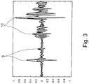
- Fig. 3 shows a section of a received signal with the associated envelope. Plotted are the individual amplitudes of the received signal over the term.
- the envelope or envelope with its much quieter profile means a reduction of the information of the received signal, which represents a simplification simplifying the evaluation of most essential signals in the determination of a level using the transit time method in the prior art.
- Evident are in the envelope four partial signals 9, 10, which differ due to their amplitudes from the other signals and thereby protrude. For the detection of such partial signals, corresponding algorithms are known in the prior art. Partial signals 9, 10 can be identified more easily if the received signal or its envelope is split, for example, into four sub-signals on the basis of the transit times. This makes it possible to run, for example, in each case the same computer routine, which determines only one maximum, in the extraction of information for the identification of the partial signals carried out after the generation of the sub-signals.
- Fig. 1 stir two reflections from the medium 1 ago and two reflections are noise due to reflections at the weld or at the shoulder of the wall. Therefore, after the identification of the partial signals 9, 10, a further classification of the partial signals 9, 10 must be carried out for further processing. From the comparison of the signal of Fig. 3 with the construction of the Fig. 1 It follows that the interfering signals lie closer in the direction of the measuring device 2 and thereby also have a shorter transit time than the signals which result from the reflection at the surface of the medium 1. Therefore, the two first sub-signals 9 in the Fig. 3 Interference signals and the other two sub-signals 10 originate from the surface of the medium 1.
- a filtering on the useful echo signals can thus be carried out, for example, by controlling the time of receiving the received signal by the signal is registered only after the lapse of a certain time.
- the advantage of a memory unit 8 becomes apparent It can be deposited that two echo signals appear from the surface of the medium in the given state of the medium in the received signal.
- the transmission signal is preferably transmitted or emitted in the direction of the medium by means of adjustable transmission signal properties as a transmission parameter or as a signal generation parameter.
- the parameters of the transmission characteristics are, for example, the frequency, the polarization or the solid angle into which the transmission signal is emitted.
- the reflection of the transmission signal in the direction of the receiver takes place.
- the received signal is recorded with adjustable reception characteristics. These parameters are, for example, the polarization, also about the frequency or the transit time, to which the received signal is still received.
- the solid angle from which the received signal is received can be realized, for example, by panning or moving an antenna serving to receive.
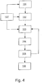
- step 103 which is already a component of the evaluation of the received signal, the received signal is subjected to a filtering, so that at least one sub-signal results, which in step 104 the extraction of at least one information or a feature or a parameter, in particular for a subsequent Identification of at least one sub-signal within the sub-signal is used.
- the subsequent identification-in particular in step 105 takes place in one embodiment by means of the Hilbert transformation and an amount formation as a variant of the identification on the basis of the amplitude of the envelope curve.
- For a frequency filtering of the time signal first of all a Fourier transformation of the received signal is carried out.
- the spectrally filtered sub-signal is then subjected to an inverse Fourier transformation in step 105 for the identification of at least one sub-signal (or of a particularly distinctive peak), so that a time signal results again.
- the identified partial signal is classified, for example via an analysis of variance, ie assigned to one of at least two classes. These are in particular to the two classes "echo signals from the surface of the medium" and "interference signals".
- the identification and the classification in particular, the information from the evaluation of the sub-signals is used in step 104.
- the classification takes place in one embodiment independently of the identification.
- a Fourier transformation and then an inverse Fourier transformation of the sub-signal or possibly further processing take place between the individual steps of the evaluation, as described above.
- the type of processing or the evaluation steps may be dependent on the type of filtering that has been used with respect to the received signal.
- the Fourier transformation is used in particular after a preceding frequency filtering of the received signal.
- the envelope is obtained by a Hilbert transform.
- the solid angle or the transit time results in the sub-signals by the received signals are used or switched through with different polarization (ie a gating with respect to the polarization) or by recovering the signals from different spatial directions by pivoting the antenna beam (ie a gating with respect to the spatial direction) or by the received signals are registered at different measuring times (ie a gating with respect to the time of reception in the sense of a time-gating).
- the output of step 105 preferably consists in echo signal information recognized as valid or detected from the surface of the medium as a function of the transit time of the signals or the distance to the antenna or in interference signal information recognized as such.
- the process variables such. B. the distance can be determined.
- the known distance from interferers superimposed or falsified evaluation data or information is excluded or hidden by interfering signals.
- the echo signal information recognized or detected as valid is received from the surface of the medium is interpreted as a distribution density as a function of the propagation time of the signals or of the distance, in which case the evaluation with regard to the process variable level is effected by statistical distribution parameters:
- the center of gravity as an estimator for the average distance between the antenna and the surface of the medium or the empirical variance
- the standard deviation as an estimator for the variation of the distance.
- model-based estimates of the distribution density or the parameters derived therefrom can also be used.
- step 103 The sequence of filtering in step 103, extraction of information or parameters, etc. in step 104 and identification or classification in step 105 is thereby possibly repeated several times.
- the received signal is partly filtered with different filters in sub-signals, and partially the sub-signals are subjected to additional filtering or further post-processing.
- the received signal is first filtered in frequency and then with respect to the polarization direction.
- filtering with respect to the direction of polarization already takes place upon receiving the received signal in step 102 and thereby before frequency filtering.
- step 106 the individual information is composed of the sub-signals in order to obtain overall information about the process variable level.
- the steps 103 to 105 can also be summarized as preprocessing, wherein the actual evaluation takes place in step 106.
- step 106 the probabilities in the identification and classification of the partial signals are preferably used for the evaluation of the information from the subsignals in order to arrive at a reliable statement about the level.
- the step 107 allows a coordination between the transmission of the transmission signal in step 101, the reception of the reception signal in step 102 and the beginning of the evaluation of the reception signal in step 103.
Landscapes
- Physics & Mathematics (AREA)
- Fluid Mechanics (AREA)
- General Physics & Mathematics (AREA)
- Electromagnetism (AREA)
- Thermal Sciences (AREA)
- Acoustics & Sound (AREA)
- Radar Systems Or Details Thereof (AREA)
- Length-Measuring Devices Using Wave Or Particle Radiation (AREA)
- Measurement Of Levels Of Liquids Or Fluent Solid Materials (AREA)
Claims (6)
- Procédé de détermination du niveau de remplissage par un fluide selon le procédé du temps de propagation, au moins un signal d'émission étant émis, au moins un signal de réception étant reçu et le signal de réception étant interprété au moins du point de vue du niveau de remplissage,
le signal de réception étant filtré en plusieurs signaux secondaires en utilisant différents critères d'interprétation réglables en tant que cotes de filtrage, une fréquence étant un critère d'interprétation, des informations étant respectivement obtenues auprès des signaux secondaires en ce qu'au moins un signal partiel est à chaque fois identifié dans les signaux secondaires, chaque signal partiel identifié étant associé à une classe parmi au moins deux classes de signaux, notamment les classes Signal d'écho et Signal parasite, et les informations obtenues étant combinées entre elles, au moins une information globale à propos du niveau de remplissage étant générée. - Procédé selon la revendication 1, caractérisé en ce que les différents critères d'interprétation, outre la fréquence, sont une polarisation et/ou un angle solide et/ou une forme de signal et/ou un instant de réception de signal.
- Procédé selon la revendication 1 ou 2, caractérisé en ce qu'une probabilité pour la fiabilité de l'identification ou de la classification est indiquée lors de l'identification et/ou de la classification.
- Procédé selon l'une des revendications 1 à 3, caractérisé en ce que le signal de réception est reçu avec des propriétés de réception réglables et en ce que le signal de réception est interprété, notamment filtré, en tenant compte des propriétés de réception.
- Procédé selon l'une des revendications 1 à 4, caractérisé en ce que le signal d'émission est émis avec des propriétés de signal d'émission réglables et en ce que le signal de réception est interprété, notamment filtré, en tenant compte des propriétés de signal d'émission.
- Dispositif (2) de détermination et/ou de surveillance du niveau de remplissage par un fluide (1), comprenant au moins une unité d'émission (4) destinée à émettre au moins un signal d'émission, comprenant au moins une unité de réception (5) destinée à recevoir au moins un signal de réception, et comprenant au moins une unité d'interprétation (6) destinée à interpréter le signal de réception, l'unité d'émission (4) et l'unité de réception (5) et l'unité d'interprétation (6) étant configurées pour mettre en oeuvre le procédé selon l'une des revendications 1 à 5.
Applications Claiming Priority (1)
| Application Number | Priority Date | Filing Date | Title |
|---|---|---|---|
| DE102012007979A DE102012007979A1 (de) | 2012-04-24 | 2012-04-24 | Verfahren zur Bestimmung des Füllstandes eines Mediums und entsprechende Vorrichtung |
Publications (3)
| Publication Number | Publication Date |
|---|---|
| EP2657664A2 EP2657664A2 (fr) | 2013-10-30 |
| EP2657664A3 EP2657664A3 (fr) | 2014-08-27 |
| EP2657664B1 true EP2657664B1 (fr) | 2018-05-30 |
Family
ID=48045231
Family Applications (1)
| Application Number | Title | Priority Date | Filing Date |
|---|---|---|---|
| EP13001447.5A Active EP2657664B1 (fr) | 2012-04-24 | 2013-03-21 | Procédé de détermination du niveau de remplissage d'un fluide et dispositif correspondant |
Country Status (5)
| Country | Link |
|---|---|
| US (1) | US9207111B2 (fr) |
| EP (1) | EP2657664B1 (fr) |
| CN (1) | CN103376145B (fr) |
| CA (1) | CA2811616C (fr) |
| DE (1) | DE102012007979A1 (fr) |
Families Citing this family (10)
| Publication number | Priority date | Publication date | Assignee | Title |
|---|---|---|---|---|
| DE102014111987A1 (de) * | 2014-08-21 | 2016-02-25 | Endress + Hauser Gmbh + Co. Kg | Vorrichtung zur Bestimmung eines Füllstands eines Schüttguts |
| DE102015100414A1 (de) * | 2015-01-13 | 2016-07-14 | Krohne Messtechnik Gmbh | Vorrichtung zur Bestimmung des Füllstands eines Mediums in einem Behälter |
| DE102016105646A1 (de) * | 2016-03-28 | 2017-09-28 | Krohne Messtechnik Gmbh | Vorrichtung zur Messung der Entfernung zu einem Objekt |
| DE102016107049B3 (de) * | 2016-04-15 | 2017-04-20 | Sick Ag | Bestimmen eines Füllstands eines Mediums |
| CN107907185B (zh) * | 2017-12-25 | 2024-04-05 | 上海昂丰装备科技有限公司 | 一种焚烧料斗内的料位检测系统及其使用方法 |
| EP3511685A1 (fr) * | 2018-01-16 | 2019-07-17 | Ovinto cvba | Évaluation améliorée de l'état de remplissage dans le transport de marchandises |
| DE102018123429A1 (de) * | 2018-09-24 | 2020-03-26 | Endress+Hauser SE+Co. KG | Füllstandsmessgerät |
| DE102020111252A1 (de) | 2020-04-24 | 2021-10-28 | Krones Aktiengesellschaft | Verfahren und Vorrichtung zur Inspektion von Behältern |
| DE102020210517A1 (de) | 2020-08-19 | 2022-02-24 | Vega Grieshaber Kg | Sensor zur Bestimmung eines Füllstands, Sensorsystem, Verwendung und Verfahren |
| CN117433606B (zh) * | 2023-12-20 | 2024-03-19 | 成都易联易通科技有限责任公司 | 粮仓物联网数据去噪方法和系统 |
Family Cites Families (15)
| Publication number | Priority date | Publication date | Assignee | Title |
|---|---|---|---|---|
| DE3337690A1 (de) * | 1983-10-17 | 1985-04-25 | VEGA Grieshaber GmbH & Co, 7620 Wolfach | Verfahren und vorrichtung zur messung des fuellstands in einem behaelter mittels schall-/ultraschallwellen |
| US5168469A (en) * | 1991-01-02 | 1992-12-01 | E. I. Du Pont De Nemours And Company | Thickness and flaw detection using time mapping into memory technique |
| DE4308373C2 (de) | 1993-03-16 | 1995-04-13 | Siemens Ag | Verfahren zur Erkennung und Separation von Nutz- und Störechos im Empfangssignal von Abstandssensoren, welche nach dem Impuls-Echo-Prinzip arbeiten |
| NO20003543L (no) * | 1999-09-06 | 2001-03-07 | Helge Balk | FremgangsmÕte ved fiskedeteksjon fra sonardata |
| US6759976B1 (en) | 2002-12-20 | 2004-07-06 | Saab Marine Electronics Ab | Method and apparatus for radar-based level gauging |
| EP1431723B1 (fr) * | 2002-12-20 | 2016-03-09 | Rosemount Tank Radar AB | Procédé et appareil pour mesurer le niveau par radar |
| DE10260962A1 (de) * | 2002-12-20 | 2004-07-01 | Endress + Hauser Gmbh + Co. Kg | Füllstandsmeßgerät und Verfahren zur Füllstandsmessung nach dem Laufzeitprinzip |
| US7800528B2 (en) * | 2007-07-31 | 2010-09-21 | Rosemount Tank Radar Ab | Radar level gauge with variable pulse parameters |
| EP2093546A1 (fr) | 2008-02-22 | 2009-08-26 | Siemens Milltronics Process Instruments Inc. | Procédé de localisation d'un écho souhaité à partir d'échos non désirés dans un système de mesure de niveau de temps de vol |
| US8224594B2 (en) | 2008-09-18 | 2012-07-17 | Enraf B.V. | Apparatus and method for dynamic peak detection, identification, and tracking in level gauging applications |
| EP2382747A1 (fr) * | 2008-12-29 | 2011-11-02 | Nxp B.V. | Changement de fréquence fractionnaire et de taux d'échantillonnage dans le domaine fréquentiel |
| DE102009055262A1 (de) | 2009-12-23 | 2011-06-30 | Endress + Hauser GmbH + Co. KG, 79689 | Verfahren zur Ermittlung und Überwachung des Füllstands eines Mediums in einem Behälter nach einem Laufzeitmessverfahren |
| EP2372318B1 (fr) | 2010-03-26 | 2020-03-18 | VEGA Grieshaber KG | Accumulation d'écho parasite dans des bruits de récipients |
| EP2418465B1 (fr) | 2010-07-19 | 2017-02-22 | VEGA Grieshaber KG | Profilage d'amplitude dans des appareils de mesure du niveau de remplissage |
| DE102010042525A1 (de) * | 2010-10-15 | 2012-04-19 | Endress + Hauser Gmbh + Co. Kg | Verfahren zur Ermittlung und Überwachung des Füllstands eines Mediums in einem Behälter mittels eines Füllstandsmessgeräts nach einem Laufzeitmessverfahren |
-
2012
- 2012-04-24 DE DE102012007979A patent/DE102012007979A1/de not_active Withdrawn
- 2012-10-03 US US13/644,021 patent/US9207111B2/en active Active
-
2013
- 2013-03-21 EP EP13001447.5A patent/EP2657664B1/fr active Active
- 2013-04-04 CA CA2811616A patent/CA2811616C/fr active Active
- 2013-04-24 CN CN201310145054.2A patent/CN103376145B/zh active Active
Non-Patent Citations (1)
| Title |
|---|
| None * |
Also Published As
| Publication number | Publication date |
|---|---|
| CA2811616A1 (fr) | 2013-10-24 |
| DE102012007979A1 (de) | 2013-10-24 |
| US9207111B2 (en) | 2015-12-08 |
| CN103376145B (zh) | 2018-03-30 |
| CN103376145A (zh) | 2013-10-30 |
| US20130276529A1 (en) | 2013-10-24 |
| EP2657664A3 (fr) | 2014-08-27 |
| CA2811616C (fr) | 2017-10-10 |
| EP2657664A2 (fr) | 2013-10-30 |
Similar Documents
| Publication | Publication Date | Title |
|---|---|---|
| EP2657664B1 (fr) | Procédé de détermination du niveau de remplissage d'un fluide et dispositif correspondant | |
| DE102012103555B4 (de) | Fußgängererfasssungsvorrichtung und Fußgängererfassungsverfahren | |
| DE102015013854B4 (de) | Verfahren und Radarvorrichtung zum Erfassen eines Zielobjekts | |
| EP2267475B1 (fr) | Procédé de radiogoniométrie et installation de radiogoniométrie destinée à détecter et suivre des angles radiogoniométriques temporellement successifs | |
| DE102010029699A1 (de) | Radarsensor und Verfahren zur Detektion von Niederschlag mit einem Radarsensor | |
| DE102013204628B4 (de) | Radarvorrichtung | |
| DE102015006032A1 (de) | Ultraschalldetektionseinrichtung und Detektionsverfahren dafür | |
| DE102014114107A1 (de) | Radarsensor | |
| WO2015010814A1 (fr) | Procédé pour déterminer et surveiller le niveau d'un fluide dans un récipient selon un procédé de mesure du temps de propagation | |
| DE102018200688B4 (de) | Verfahren und Vorrichtung zum Betreiben eines akustischen Sensors | |
| WO2014075839A1 (fr) | Dispositif et procédé pour la détermination de l'angle de hausse dans un système de radar | |
| DE102012021239A1 (de) | Verfahren zur Detektion einer Interferenz in einem Empfangssignal eines Radarsensors, Fahrassistenzeinrichtung und Kraftfahrzeug | |
| DE102017119182B4 (de) | Verfahren und Vorrichtung zur rechnerisch effizienten Zielerfassung und Verfolgung unter Verwendung eines Radars | |
| DE102019100380A1 (de) | Radarvorrichtung | |
| DE102017004808B3 (de) | Steuervorrichtung und Verfahren zur Steuerung einer Höhe eines Auslegers eines Fahrzeugs | |
| DE102021100695A1 (de) | Verfahren zum Betrieb eines Topologie-erfassenden Radarsystems innerhalb eines Behälters | |
| DE102016123207A1 (de) | Verfahren zur Detektion eines Störeinflusses bei einem Radarsignal | |
| DE102020105314A1 (de) | Verfahren zur Bereitstellung von wenigstens einer Zielinformation | |
| DE102019216017A1 (de) | Verfahren und Vorrichtung zur Verarbeitung einer Doppler-Range-Matrix und Radarsystem | |
| EP3018490B1 (fr) | Procede de detection d'une interference dans un signal de reception d'un capteur radar d'un vehicule automobile, dispositif de calcul, systeme d'assistance a la conduite, vehicule automobile et produit programme informatique | |
| DE102017129168A1 (de) | Verfahren zur Spektrumklassifizierung, Verfahren zur Klassifizierung sowie Empfangsvorrichtung | |
| WO2021122167A1 (fr) | Procédé de vérification d'un capteur radar d'un véhicule | |
| EP3575755B1 (fr) | Appareil de mesure de niveau de remplissage à commande d'antenne optimisée et méthode de mesure de niveau | |
| EP2699933B1 (fr) | Procédé et dispositif de détermination de paramètres d'une cible | |
| WO2020069922A1 (fr) | Procédé de fourniture d'informations d'objet à propos d'objets statiques dans un environnement d'un véhicule |
Legal Events
| Date | Code | Title | Description |
|---|---|---|---|
| PUAI | Public reference made under article 153(3) epc to a published international application that has entered the european phase |
Free format text: ORIGINAL CODE: 0009012 |
|
| AK | Designated contracting states |
Kind code of ref document: A2 Designated state(s): AL AT BE BG CH CY CZ DE DK EE ES FI FR GB GR HR HU IE IS IT LI LT LU LV MC MK MT NL NO PL PT RO RS SE SI SK SM TR |
|
| AX | Request for extension of the european patent |
Extension state: BA ME |
|
| PUAL | Search report despatched |
Free format text: ORIGINAL CODE: 0009013 |
|
| RIC1 | Information provided on ipc code assigned before grant |
Ipc: G01F 23/284 20060101AFI20140623BHEP |
|
| AK | Designated contracting states |
Kind code of ref document: A3 Designated state(s): AL AT BE BG CH CY CZ DE DK EE ES FI FR GB GR HR HU IE IS IT LI LT LU LV MC MK MT NL NO PL PT RO RS SE SI SK SM TR |
|
| AX | Request for extension of the european patent |
Extension state: BA ME |
|
| 17P | Request for examination filed |
Effective date: 20141218 |
|
| RBV | Designated contracting states (corrected) |
Designated state(s): AL AT BE BG CH CY CZ DE DK EE ES FI FR GB GR HR HU IE IS IT LI LT LU LV MC MK MT NL NO PL PT RO RS SE SI SK SM TR |
|
| RIC1 | Information provided on ipc code assigned before grant |
Ipc: G01F 25/00 20060101ALN20171115BHEP Ipc: G01F 23/284 20060101AFI20171115BHEP Ipc: G01F 23/00 20060101ALN20171115BHEP Ipc: G01F 23/296 20060101ALN20171115BHEP |
|
| GRAP | Despatch of communication of intention to grant a patent |
Free format text: ORIGINAL CODE: EPIDOSNIGR1 |
|
| STAA | Information on the status of an ep patent application or granted ep patent |
Free format text: STATUS: GRANT OF PATENT IS INTENDED |
|
| RIC1 | Information provided on ipc code assigned before grant |
Ipc: G01F 23/00 20060101ALN20171214BHEP Ipc: G01F 23/296 20060101ALN20171214BHEP Ipc: G01F 23/284 20060101AFI20171214BHEP Ipc: G01F 25/00 20060101ALN20171214BHEP |
|
| GRAS | Grant fee paid |
Free format text: ORIGINAL CODE: EPIDOSNIGR3 |
|
| INTG | Intention to grant announced |
Effective date: 20180111 |
|
| GRAA | (expected) grant |
Free format text: ORIGINAL CODE: 0009210 |
|
| STAA | Information on the status of an ep patent application or granted ep patent |
Free format text: STATUS: THE PATENT HAS BEEN GRANTED |
|
| AK | Designated contracting states |
Kind code of ref document: B1 Designated state(s): AL AT BE BG CH CY CZ DE DK EE ES FI FR GB GR HR HU IE IS IT LI LT LU LV MC MK MT NL NO PL PT RO RS SE SI SK SM TR |
|
| REG | Reference to a national code |
Ref country code: GB Ref legal event code: FG4D Free format text: NOT ENGLISH |
|
| REG | Reference to a national code |
Ref country code: CH Ref legal event code: EP |
|
| REG | Reference to a national code |
Ref country code: AT Ref legal event code: REF Ref document number: 1004095 Country of ref document: AT Kind code of ref document: T Effective date: 20180615 |
|
| REG | Reference to a national code |
Ref country code: IE Ref legal event code: FG4D Free format text: LANGUAGE OF EP DOCUMENT: GERMAN |
|
| REG | Reference to a national code |
Ref country code: DE Ref legal event code: R096 Ref document number: 502013010215 Country of ref document: DE |
|
| REG | Reference to a national code |
Ref country code: NL Ref legal event code: MP Effective date: 20180530 |
|
| REG | Reference to a national code |
Ref country code: LT Ref legal event code: MG4D |
|
| PG25 | Lapsed in a contracting state [announced via postgrant information from national office to epo] |
Ref country code: BG Free format text: LAPSE BECAUSE OF FAILURE TO SUBMIT A TRANSLATION OF THE DESCRIPTION OR TO PAY THE FEE WITHIN THE PRESCRIBED TIME-LIMIT Effective date: 20180830 Ref country code: NO Free format text: LAPSE BECAUSE OF FAILURE TO SUBMIT A TRANSLATION OF THE DESCRIPTION OR TO PAY THE FEE WITHIN THE PRESCRIBED TIME-LIMIT Effective date: 20180830 Ref country code: SE Free format text: LAPSE BECAUSE OF FAILURE TO SUBMIT A TRANSLATION OF THE DESCRIPTION OR TO PAY THE FEE WITHIN THE PRESCRIBED TIME-LIMIT Effective date: 20180530 Ref country code: FI Free format text: LAPSE BECAUSE OF FAILURE TO SUBMIT A TRANSLATION OF THE DESCRIPTION OR TO PAY THE FEE WITHIN THE PRESCRIBED TIME-LIMIT Effective date: 20180530 Ref country code: CY Free format text: LAPSE BECAUSE OF FAILURE TO SUBMIT A TRANSLATION OF THE DESCRIPTION OR TO PAY THE FEE WITHIN THE PRESCRIBED TIME-LIMIT Effective date: 20180530 Ref country code: ES Free format text: LAPSE BECAUSE OF FAILURE TO SUBMIT A TRANSLATION OF THE DESCRIPTION OR TO PAY THE FEE WITHIN THE PRESCRIBED TIME-LIMIT Effective date: 20180530 Ref country code: LT Free format text: LAPSE BECAUSE OF FAILURE TO SUBMIT A TRANSLATION OF THE DESCRIPTION OR TO PAY THE FEE WITHIN THE PRESCRIBED TIME-LIMIT Effective date: 20180530 |
|
| PG25 | Lapsed in a contracting state [announced via postgrant information from national office to epo] |
Ref country code: GR Free format text: LAPSE BECAUSE OF FAILURE TO SUBMIT A TRANSLATION OF THE DESCRIPTION OR TO PAY THE FEE WITHIN THE PRESCRIBED TIME-LIMIT Effective date: 20180831 Ref country code: HR Free format text: LAPSE BECAUSE OF FAILURE TO SUBMIT A TRANSLATION OF THE DESCRIPTION OR TO PAY THE FEE WITHIN THE PRESCRIBED TIME-LIMIT Effective date: 20180530 Ref country code: LV Free format text: LAPSE BECAUSE OF FAILURE TO SUBMIT A TRANSLATION OF THE DESCRIPTION OR TO PAY THE FEE WITHIN THE PRESCRIBED TIME-LIMIT Effective date: 20180530 Ref country code: RS Free format text: LAPSE BECAUSE OF FAILURE TO SUBMIT A TRANSLATION OF THE DESCRIPTION OR TO PAY THE FEE WITHIN THE PRESCRIBED TIME-LIMIT Effective date: 20180530 |
|
| PG25 | Lapsed in a contracting state [announced via postgrant information from national office to epo] |
Ref country code: NL Free format text: LAPSE BECAUSE OF FAILURE TO SUBMIT A TRANSLATION OF THE DESCRIPTION OR TO PAY THE FEE WITHIN THE PRESCRIBED TIME-LIMIT Effective date: 20180530 |
|
| PG25 | Lapsed in a contracting state [announced via postgrant information from national office to epo] |
Ref country code: SK Free format text: LAPSE BECAUSE OF FAILURE TO SUBMIT A TRANSLATION OF THE DESCRIPTION OR TO PAY THE FEE WITHIN THE PRESCRIBED TIME-LIMIT Effective date: 20180530 Ref country code: RO Free format text: LAPSE BECAUSE OF FAILURE TO SUBMIT A TRANSLATION OF THE DESCRIPTION OR TO PAY THE FEE WITHIN THE PRESCRIBED TIME-LIMIT Effective date: 20180530 Ref country code: EE Free format text: LAPSE BECAUSE OF FAILURE TO SUBMIT A TRANSLATION OF THE DESCRIPTION OR TO PAY THE FEE WITHIN THE PRESCRIBED TIME-LIMIT Effective date: 20180530 Ref country code: CZ Free format text: LAPSE BECAUSE OF FAILURE TO SUBMIT A TRANSLATION OF THE DESCRIPTION OR TO PAY THE FEE WITHIN THE PRESCRIBED TIME-LIMIT Effective date: 20180530 Ref country code: DK Free format text: LAPSE BECAUSE OF FAILURE TO SUBMIT A TRANSLATION OF THE DESCRIPTION OR TO PAY THE FEE WITHIN THE PRESCRIBED TIME-LIMIT Effective date: 20180530 Ref country code: PL Free format text: LAPSE BECAUSE OF FAILURE TO SUBMIT A TRANSLATION OF THE DESCRIPTION OR TO PAY THE FEE WITHIN THE PRESCRIBED TIME-LIMIT Effective date: 20180530 |
|
| PG25 | Lapsed in a contracting state [announced via postgrant information from national office to epo] |
Ref country code: IT Free format text: LAPSE BECAUSE OF FAILURE TO SUBMIT A TRANSLATION OF THE DESCRIPTION OR TO PAY THE FEE WITHIN THE PRESCRIBED TIME-LIMIT Effective date: 20180530 Ref country code: SM Free format text: LAPSE BECAUSE OF FAILURE TO SUBMIT A TRANSLATION OF THE DESCRIPTION OR TO PAY THE FEE WITHIN THE PRESCRIBED TIME-LIMIT Effective date: 20180530 |
|
| REG | Reference to a national code |
Ref country code: DE Ref legal event code: R097 Ref document number: 502013010215 Country of ref document: DE |
|
| PLBE | No opposition filed within time limit |
Free format text: ORIGINAL CODE: 0009261 |
|
| STAA | Information on the status of an ep patent application or granted ep patent |
Free format text: STATUS: NO OPPOSITION FILED WITHIN TIME LIMIT |
|
| 26N | No opposition filed |
Effective date: 20190301 |
|
| PG25 | Lapsed in a contracting state [announced via postgrant information from national office to epo] |
Ref country code: SI Free format text: LAPSE BECAUSE OF FAILURE TO SUBMIT A TRANSLATION OF THE DESCRIPTION OR TO PAY THE FEE WITHIN THE PRESCRIBED TIME-LIMIT Effective date: 20180530 |
|
| PG25 | Lapsed in a contracting state [announced via postgrant information from national office to epo] |
Ref country code: MC Free format text: LAPSE BECAUSE OF FAILURE TO SUBMIT A TRANSLATION OF THE DESCRIPTION OR TO PAY THE FEE WITHIN THE PRESCRIBED TIME-LIMIT Effective date: 20180530 |
|
| GBPC | Gb: european patent ceased through non-payment of renewal fee |
Effective date: 20190321 |
|
| PG25 | Lapsed in a contracting state [announced via postgrant information from national office to epo] |
Ref country code: AL Free format text: LAPSE BECAUSE OF FAILURE TO SUBMIT A TRANSLATION OF THE DESCRIPTION OR TO PAY THE FEE WITHIN THE PRESCRIBED TIME-LIMIT Effective date: 20180530 Ref country code: LU Free format text: LAPSE BECAUSE OF NON-PAYMENT OF DUE FEES Effective date: 20190321 |
|
| REG | Reference to a national code |
Ref country code: BE Ref legal event code: MM Effective date: 20190331 |
|
| PG25 | Lapsed in a contracting state [announced via postgrant information from national office to epo] |
Ref country code: IE Free format text: LAPSE BECAUSE OF NON-PAYMENT OF DUE FEES Effective date: 20190321 Ref country code: GB Free format text: LAPSE BECAUSE OF NON-PAYMENT OF DUE FEES Effective date: 20190321 |
|
| PG25 | Lapsed in a contracting state [announced via postgrant information from national office to epo] |
Ref country code: BE Free format text: LAPSE BECAUSE OF NON-PAYMENT OF DUE FEES Effective date: 20190331 |
|
| PG25 | Lapsed in a contracting state [announced via postgrant information from national office to epo] |
Ref country code: TR Free format text: LAPSE BECAUSE OF FAILURE TO SUBMIT A TRANSLATION OF THE DESCRIPTION OR TO PAY THE FEE WITHIN THE PRESCRIBED TIME-LIMIT Effective date: 20180530 |
|
| PG25 | Lapsed in a contracting state [announced via postgrant information from national office to epo] |
Ref country code: PT Free format text: LAPSE BECAUSE OF FAILURE TO SUBMIT A TRANSLATION OF THE DESCRIPTION OR TO PAY THE FEE WITHIN THE PRESCRIBED TIME-LIMIT Effective date: 20181001 Ref country code: MT Free format text: LAPSE BECAUSE OF FAILURE TO SUBMIT A TRANSLATION OF THE DESCRIPTION OR TO PAY THE FEE WITHIN THE PRESCRIBED TIME-LIMIT Effective date: 20180530 |
|
| REG | Reference to a national code |
Ref country code: AT Ref legal event code: MM01 Ref document number: 1004095 Country of ref document: AT Kind code of ref document: T Effective date: 20190321 |
|
| PG25 | Lapsed in a contracting state [announced via postgrant information from national office to epo] |
Ref country code: AT Free format text: LAPSE BECAUSE OF NON-PAYMENT OF DUE FEES Effective date: 20190321 |
|
| PG25 | Lapsed in a contracting state [announced via postgrant information from national office to epo] |
Ref country code: IS Free format text: LAPSE BECAUSE OF FAILURE TO SUBMIT A TRANSLATION OF THE DESCRIPTION OR TO PAY THE FEE WITHIN THE PRESCRIBED TIME-LIMIT Effective date: 20180930 |
|
| PG25 | Lapsed in a contracting state [announced via postgrant information from national office to epo] |
Ref country code: HU Free format text: LAPSE BECAUSE OF FAILURE TO SUBMIT A TRANSLATION OF THE DESCRIPTION OR TO PAY THE FEE WITHIN THE PRESCRIBED TIME-LIMIT; INVALID AB INITIO Effective date: 20130321 |
|
| PG25 | Lapsed in a contracting state [announced via postgrant information from national office to epo] |
Ref country code: MK Free format text: LAPSE BECAUSE OF FAILURE TO SUBMIT A TRANSLATION OF THE DESCRIPTION OR TO PAY THE FEE WITHIN THE PRESCRIBED TIME-LIMIT Effective date: 20180530 |
|
| PGFP | Annual fee paid to national office [announced via postgrant information from national office to epo] |
Ref country code: FR Payment date: 20230324 Year of fee payment: 11 |
|
| P01 | Opt-out of the competence of the unified patent court (upc) registered |
Effective date: 20230607 |
|
| PGFP | Annual fee paid to national office [announced via postgrant information from national office to epo] |
Ref country code: DE Payment date: 20230519 Year of fee payment: 11 Ref country code: CH Payment date: 20230402 Year of fee payment: 11 |